Article

Rectifiers’ Design and Optimization for a Dual-Channel RF Energy Harvester

Department of Industrial and Information Engineering, University of L’Aquila, 67100 L’Aquila, Italy
*
Author to whom correspondence should be addressed.
J. Low Power Electron. Appl. 2020, 10(2), 11; https://doi.org/10.3390/jlpea10020011
Submission received: 17 February 2020 / Revised: 22 March 2020 / Accepted: 2 April 2020 / Published: 4 April 2020
(This article belongs to the Special Issue Low-Power RF Energy Harvesting for IoT Devices)

Abstract

:
This paper presents the design and implementation of two front-ends for RF (Radio Frequency) energy harvesting, comparing them with the commercial one—P2110 by Powercast Co. (Pittsburgh, PA, USA) Both devices are implemented on a discrete element board with microstrip lines combined with lumped elements and are optimized for two different input power levels (−10 dBm and 10 dBm, respectively), at the GSM900 frequencies. The load has been fixed at 5kΩ, after a load-pull analysis on systems. The rectifiers stages implement two different Schottky diodes in two different topologies: a single diode and a 2-stage Dickson’s charge pump. The second one is compared with the P2110 by generating RF fields at 915 MHz with the Powercast Powerspot. The main aim of this work is to design simple and efficient low-cost devices, which can be used as a power supply for low-power autonomous sensors, with better performances than the current solutions of state-of-the-art equipment, providing an acceptable voltage level on the load. Measurements have been conducted for input power range −20 dBm up to 10 dBm; the best power conversion efficiency (PCE) is obtained with the second design, which reaches a value of 70% at 915 MHz. In particular, the proposed device exhibited better performance compared to the P2110 commercial device, allowing a maximum distance of operation of up to 22 meters from the dedicated RF power source, making it suitable even for IoT (Internet of Things) applications.

1. Introduction

In recent years, the great use of low-power autonomous systems and sensors [1,2,3,4,5,6] increased the need for self-sustainable devices, which are capable of harvesting and using energy from the environment, particularly for those that need a continuous power supply (such as human health monitoring systems) [7,8,9,10,11,12,13]. These devices, such as low-voltage front-ends for photomultiplier [4] or monitoring systems for buildings with a low power consumption [6], can use energy scavenged from the environment, which is typically poor but enough to ensure the system functionality. Since this energy is available in many different forms (thermal, vibrational, …), some works focused on multi-source energy harvesters, combining techniques to compensate for this lack of retrievable energy [11]. In this perspective, the development of wireless communication with smartphones and RF transmitters provided a steady availability of electromagnetic waves, which corresponds to free RF energy [13]. Energy harvesting’s aim is to exploit the generated field as a source of power, collecting waves in the environment and converting them in a DC electrical signal. Good efficiency levels are reached with solutions proposed in other papers: some of them use a nonvolatile memory structure [12], while others propose IC structures with CMOS technology [7]. Moreover, a double-band design has been proposed, which uses a diplexer to harvest RF power at two frequencies [5]. Despite their efficiency level (that usually reaches 50%), these have a complex design and are not simple to realize. In this work, we focused on the possibility to design a simple circuit configuration with easily available components in order to provide a simple energy harvesting system with a good power conversion efficiency. The most commonly available frequencies of RF signals cover a spectrum range from about 400 MHz to 2.5 GHz [10], which includes mobile phones and Wi-Fi devices’ bands. Despite this, the amount of harvested energy is strongly influenced by the surroundings, such as the distance from RF sources. Several designs capable of converting RF into DC energy have already been proposed, usually working from −30 to 30 dBm, with a peak efficiency of 80% [14,15]. As a drawback, a standard urban environment has an available power maximum peak of about −30 dBm, distributed across multiple frequency spectra. In this perspective, some commercial devices able to work with their own generated RF source have been designed, such as the Powerspot, a 3 W RF transmitter. This commercial device is sold for working with Powercast harvesters [16].
A generic RF energy harvesting (EH) system is composed of four main blocks (see Figure 1): the antenna, which captures the electromagnetic waves and generates an electric RF signal; the matching network, needed to transfer the maximum amount of input power from the antenna to the rectifier, also avoiding energy reflection; the rectifier, which converts the RF signal to a DC voltage on the load; and, finally, the energy storage section, for storing harvested energy and for filtering spikes (this can simply consist in a shunt capacitor) [17].
In this work, the aim is to propose an effective, optimized, and repeatable design method, as a result of previously conducted works [18,19,20], in order to improve the performance of RF EH systems with standard architecture, as shown in Figure 1. To prove the validity of the proposed technique, a prototype board has been implemented and a performance comparison with a commercial RF energy harvester, the PB2110 from Powercast Co. [21], has been conducted and reported.
All harvesters used the same antenna, sold with the evaluation board of the Powercast P2110 [22], to ensure a comparison between commercial and designed harvesters. Matching networks are made by mixed lumped and distributed elements, in order to have more degrees of freedom in designing them. Since a good network has not to be dissipative, resistive elements are not recommended for this kind of system. Since the rectifier section needs diodes with a low junction voltage and fast switching times, Schottky diodes are the best choice for it, because of their low junction capacitance and their small amount of required power, to minimize losses and maximize available power [23,24,25,26]. Using a more complex topology, such as a full-bridge rectifier or a voltage multiplier instead of a single diode, brings a greater voltage value on the load; however, the greater the number of diodes used, the greater the power absorption of the device, significantly reducing its overall efficiency. Moreover, diodes are non-linear devices that work as a variable impedance that changes with input power itself, making it more difficult to design an efficient matching network.
Concerning the harvester efficiency, several definitions, depending on the considered section where it is calculated, are reported in the literature. In this study, the definition of the harvester power conversion efficiency (PCE) is as follows [27]:
η % = V L I L P i n 100
where V L and I L are the output voltage and current measured on the load, respectively, while P i n is the available input power that the antenna delivers towards the matching network and, therefore, to the harvesting circuitry.
This work is organized as follows: in Section 2, the design method and optimization strategy of the designed two harvesters are presented and discussed; in Section 3, the measured results are reported; and, finally, Section 4 shows the conclusions.

2. Design Method and Optimization

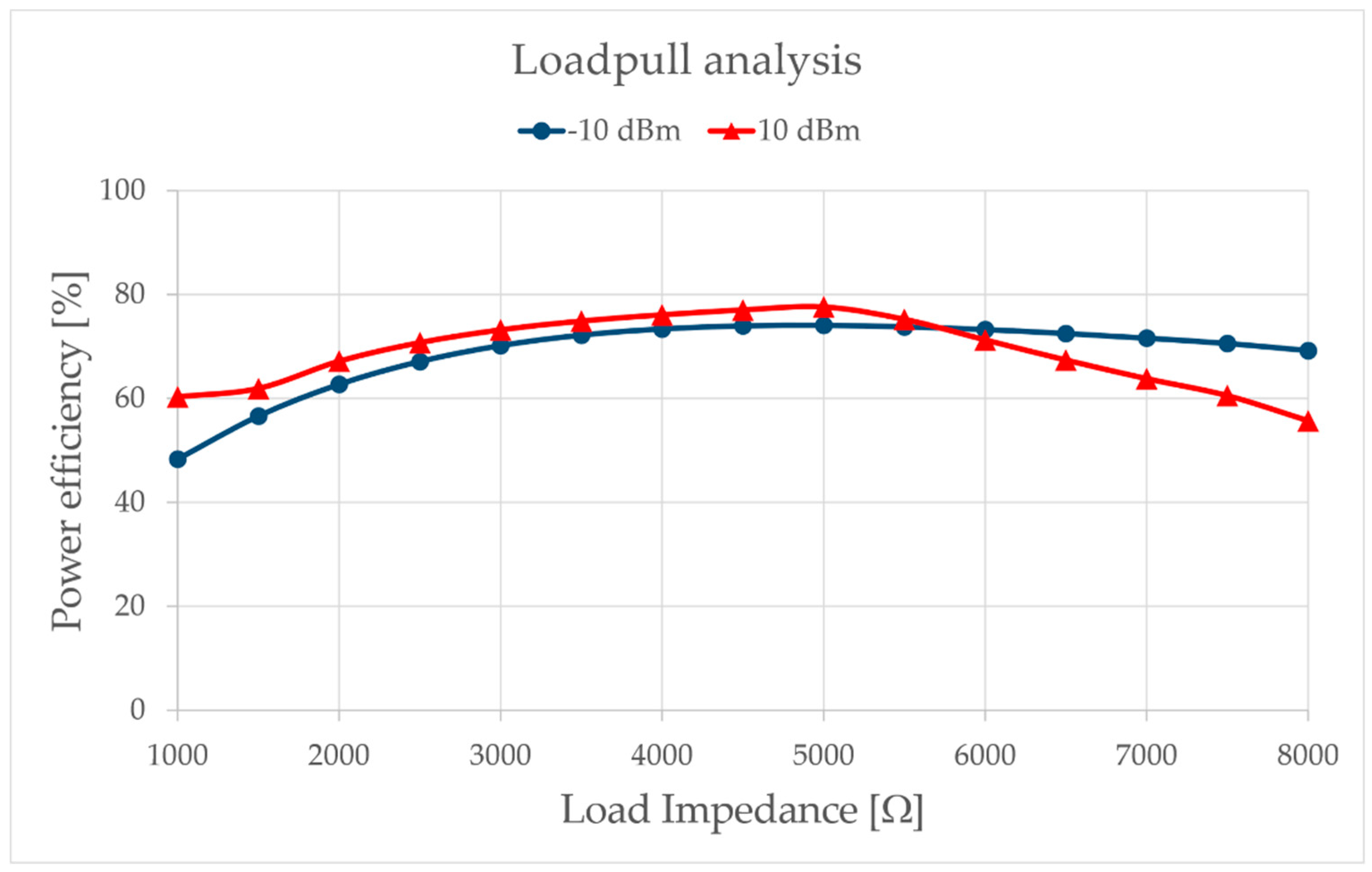
Two devices have been designed for different input power levels: an HPD (high-power device), optimized for 10 dBm, in order to make a comparison with the commercial device P2110, and an LPD (low-power device) optimized for a −10 dBm level to work with a lower power availability, which is below the Powercast input power range of operation. The LPD rectifier topology is based on a single SMS7630 diode by Skyworks Solution Inc. [28], which has a junction voltage of 0.34 V. The HPD implements a 2-stage voltage multiplier [29], using two HSMS-2852 by Avago Technologies [30], a couple of series diodes in a single package. Both circuits are implemented on a TLX8 substrate by Taconic [31] with microstrip transmission lines. The lumped elements used for matching networks are from the GJM1555 series capacitors and LQW15AN inductors by Murata (except for the LPD shunt inductor, which is a 0805CS by Coilcraft). For both the circuits, simulated and measured load-pull analyses have been conducted to find the best value of impedance that maximizes efficiency; then, a study has been conducted for different input power levels with fixed loads. From this investigation, it comes out that the best efficiency is obtained for a load of about 5 kΩ, as reported in Figure 2. The high-level schematics of both designed systems are shown in Figure 3.
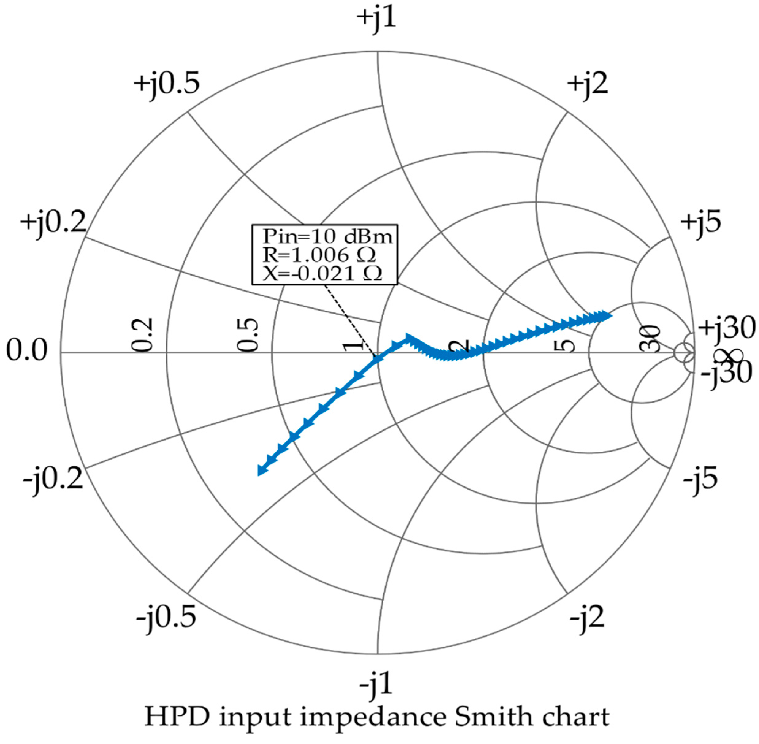
Design and simulations have been conducted within the AWR Environment Design software by Cadence Design Systems, Inc. (San Jose, CA, USA) The diodes were simulated using their non-linear SPICE-model parameters. As a first design, ideal lines and lumped elements were used. The LPD matching network is made by 3 lumped elements (shunt inductor, series inductor, and shunt capacitor), while HPD’s one is a 5 elements network (series inductor and two inductor-capacitor L-type networks). Since diodes are non-linear devices, the impedance of the rectifier is affected by the input power level [32,33]; thus, the rectifiers have been matched to the antenna for the selected input power levels Pin (−10 dBm for the LPD and 10 dBm for the HPD). Then, the values of both lumped elements and microstrips have been optimized using the Smith chart, as shown for HPD in Figure 4, for different values of Pin; to get a good matching, the impedance of the rectifier circuit must be equal to the antenna impedance at the working frequency and the considered power level.
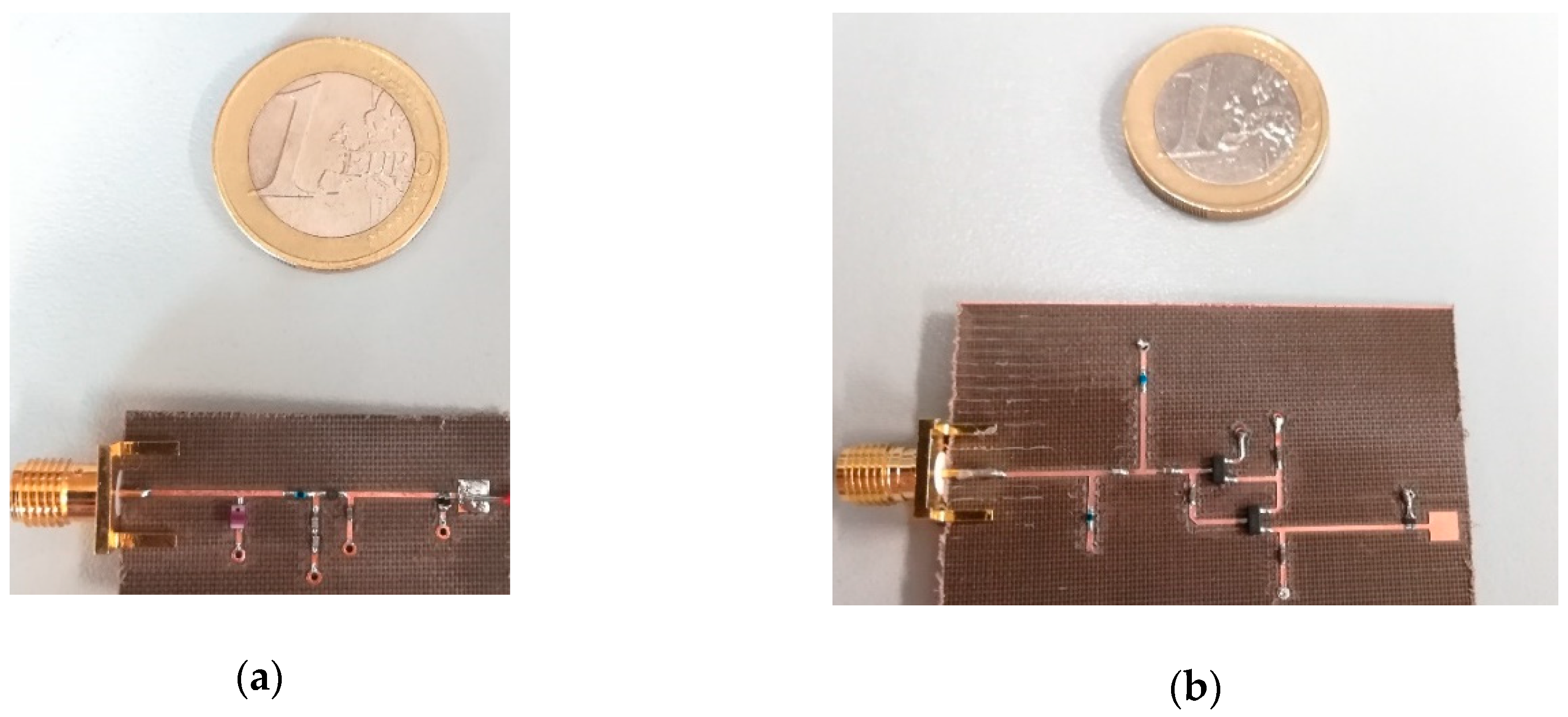
Table 1 and Table 2 report the used components in both definitive layouts, while in Figure 5a,b the implemented prototype boards for the LPD and HPD EH circuits are depicted, respectively; simulations have been conducted using the available 2-port S-parameters of commercial components. L5 was used to represents the parasitic inductive effect of the input port microstrip. Substituting ideal lines with microstrips introduced an inductive effect that has been compensated by removing the lumped element, in order to maintain a good impedance matching.

3. Simulations and Experimental Results

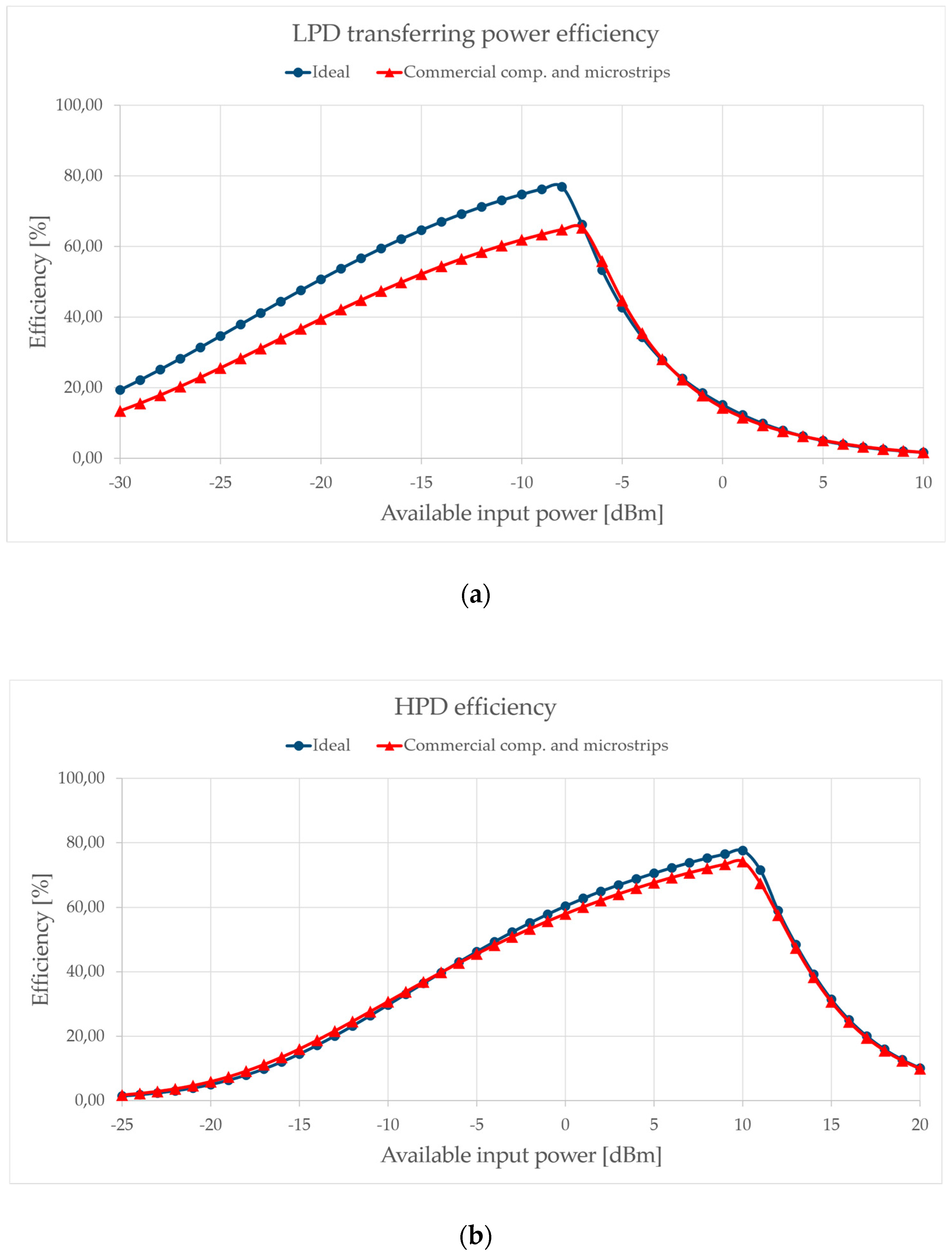
As mentioned, both circuits have been preliminarily simulated on AWR. The simulated plot of both circuit efficiency is shown in Figure 6. The best PCE is reached for input power levels near the chosen one for the optimization, exceeding 65%.
As shown, the discrepancy between ideal and commercial components is more evident in LPD than in HPD. This is because of the different diode model used, which is more precise for the second one. Moreover, due to the lower power levels, LPD is much more sensitive to the parasitic effects of the lumped elements.
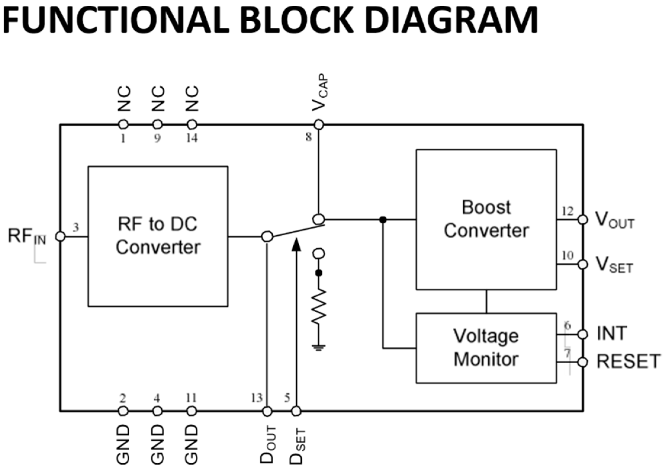
After simulation sessions, the two designed circuits have been physically realized and tested. The transferred power on the load has been measured and compared with the P2110, by connecting them to the same RF power generator. The chosen reference load is always 5 kΩ for the three systems. Since Powercast implements a DC/DC voltage regulator, it has been excluded in order to perform a fair comparison between the commercial harvester and the implemented prototypes by testing only the RF to DC section as it represents the core of the RF energy harvesting circuitry. In Figure 7, the functional block diagram of P2110 is shown [21]: the test reference load has been connected before the DC/DC boost converter, at VCAP pin, leaving the DSET pin unconnected, so that VCAP is connected to DOUT, which is the harvester analog output that provides a voltage proportional to the harvested power. In order to guarantee the boost converter not to influence the RF harvester characterization process, the RESET pin has been driven at a high logic level by means of an external voltage generator in order to disable VOUT and the voltage monitor.
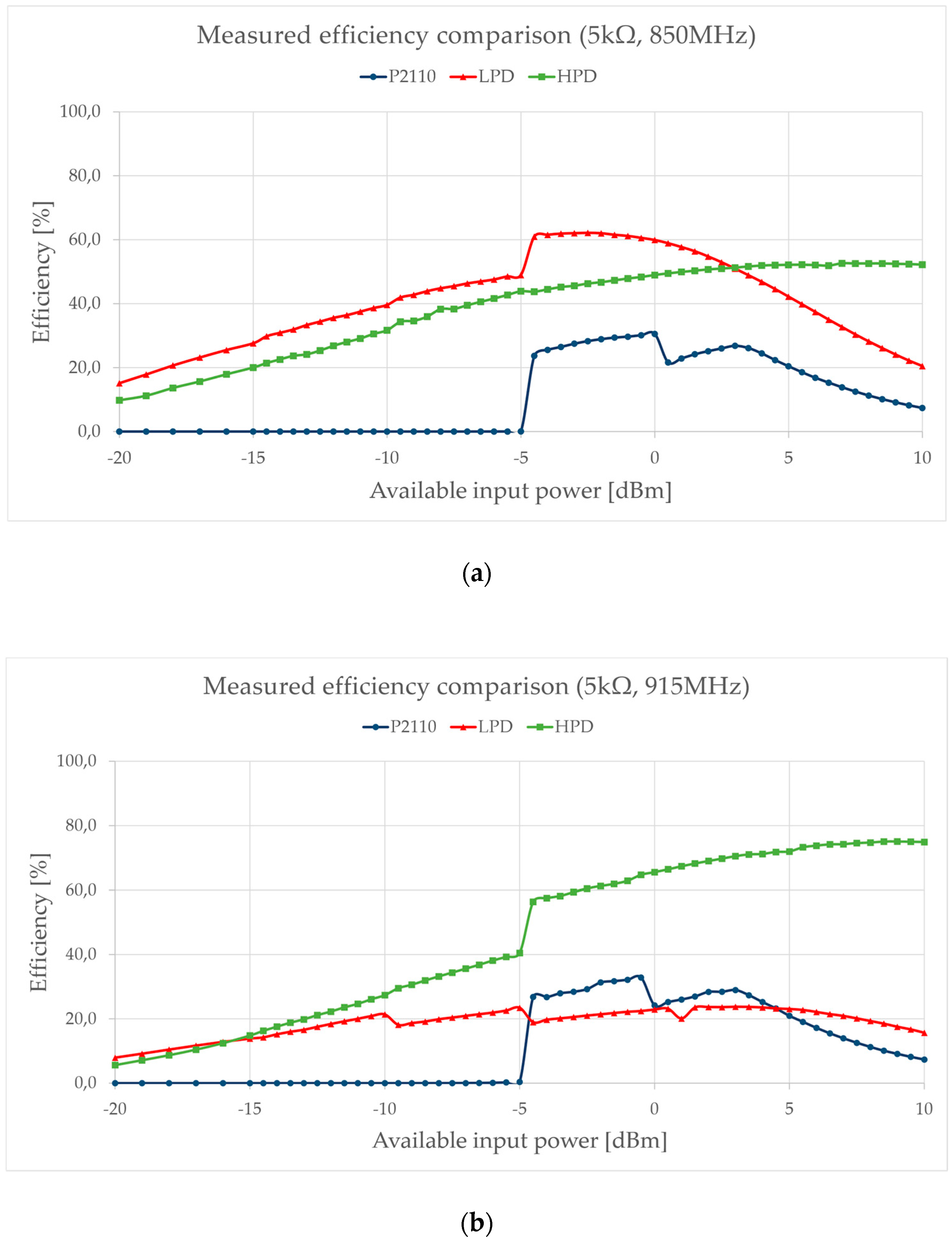
For better accuracy, both output load DC voltage and DC current have been measured simultaneously and the output harvested power has been calculated as the product of them. As shown in Figure 8, the HPD circuit reaches its maximum efficiency for an input signal frequency of 915 MHz, exceeding 70% above 5 dBm input power, and has a good efficiency at 850 MHz too. LPD showed a small overall efficiency at 915 MHz remaining similar down to 850 MHz, which is the circuit’s best matching frequency. On the other hand, the Powercast P2110 turned off for input power levels lower than −5 dBm, at each frequency. In Figure 8 shows the comparison between LPD, HPD, and P2110 efficiency.
As a further comparison, P2110 and HPD have been measured in an outdoor, free-space environment too, connecting a Powercast patch antenna to them and then generating an electromagnetic source signal with the Powercast Powerspot transmitter, which radiates a 3W RF power at 915 MHz (see Figure 9), specifically provided for Powercast harvesting devices. The LPD has not been measured outdoors because, due to its lower working power levels, it is not suitable for this kind of application and it is not directly comparable with the other two devices, while an overall test bench comparison of the three harvesters is reported in Figure 8. The P2110 barely worked 20 m away from the source, while the HPD still worked at 22 m. Voltage and current have been measured as before, while input power has been estimated by Friis’ transmission equation. Of course, a better analysis could be conducted in an anechoic chamber, avoiding field reflections and external sources to have greater accuracy. Table 3 summarizes the measurement results. The drop at a distance of 4 m is related to outdoor environment problems, such as signal interferences and multiple paths caused by the external source and the surrounding.

4. Conclusions

In this work, we have presented the design of two RF energy harvesting circuits, compared with the commercial one—P2110 by Powercast Co. Designed devices used commercial components and Schottky diode and were realized on a lossy substrate. All the used elements are low-cost components. Moreover, both the designed devices have a simple topology and are easily feasible; this is especially needed for IoT systems, where a great number of low-power sensors and devices are used, so a continuous power supply is a significant part of the application. Due to this, the designed system is suitable for a high-scale production with minimal costs and still maintaining good performance that is comparable (and superior, as is the case of HPD) with current commercial solutions. Due to the small power density commonly available in an urban environment, it is also helpful to design devices that can work with a lower power availability, maintaining an acceptable efficiency. In outdoor measurements, HPD managed to provide a good voltage level on its load without any DC voltage regulators, even at a distance of several meters. Good overall efficiency levels are reached for either LPD, HPD, or P2110, while the proposed harvesters are able to work a superior input signal power range with greater efficiency, becoming a very good candidate even for low-voltage, low-power RF energy harvesting suitable for IoT devices and other low-power applications.

Author Contributions

Conceptualization: I.U., D.C.; writing—original draft preparation: D.C.; writing—review and editing: I.U.; supervision: G.F. All authors have read and agreed to the published version of the manuscript.

Funding

This research received no external funding.

Acknowledgments

We would like to acknowledge Alfiero Leoni for his expertise and his support during these latest years. His enthusiasm and knowledge about the energy harvesting field have been an inspiration for this work.

Conflicts of Interest

The authors declare no conflict of interest.

References

  1. De Rubeis, T.; Nardi, I.; Muttillo, M.; Ranieri, S.; Ambrosini, D. Room and window geometry influence for daylight harvesting maximization—Effects on energy savings in an academic classroom. Energy Proc. 2018, 148, 1090–1097. [Google Scholar] [CrossRef]
  2. Pantoli, L.; Muttillo, M.; Stornelli, V.; Ferri, G.; Gabriele, T. A Low Cost Flexible Power Line Communication System. In Lecture Notes in Electrical Engineering; Springer: Cham, Switzerland, 2017; pp. 413–420. [Google Scholar]
  3. Barile, G.; Leoni, A.; Pantoli, L.; Stornelli, V. Real-Time Autonomous System for Structural and Environmental Monitoring of Dynamic Events. Electronics 2018, 7, 420. [Google Scholar] [CrossRef] [Green Version]
  4. Barile, G.; Leoni, A.; Pantoli, L.; Safari, L.; Stornelli, V. A New VCII Based Low-Power Low-Voltage Front-end for Silicon Photomultipliers. In Proceedings of the 2018 3rd International Conference on Smart and Sustainable Technologies (SpliTech), Split, Croatia, 26–29 June 2018; ISBN: 978-953290083-5. [Google Scholar]
  5. Leoni, A.; Pantoli, L.; Stornelli, V.; Ferri, G.; Šolić, P.; Russo, M. A combined 90/900 MHz IC architecture for power-assisting in IoT applications. J. Commun. Softw. Syst. 2018, 14, 27–32. [Google Scholar]
  6. Gabriele, T.; Pantoli, L.; Stornelli, V.; Chiulli, D.; Muttillo, M. Smart power management system for home appliances and wellness based on wireless sensors network and mobile technology. In Proceedings of the AISEM, Trento, Italy, 3–5 February 2015. [Google Scholar]
  7. Pantoli, L.; Leoni, A.; Stornelli, V.; Ferri, G. An IC architecture for RF Energy Harvesting systems. J. Commun. Softw. Syst 2017, 13, 96. [Google Scholar] [CrossRef] [Green Version]
  8. Al Agha, K.; Bertin, M.; Dang, T.; Guitton, A.; Minet, P.; Val, T.; Viollet, J. Which Wireless Technology for Industrial Wireless Sensor Networks? The Development of OCARI Technology. IEEE Trans. Ind. Electron. 2009, 56, 4266–4278. [Google Scholar] [CrossRef]
  9. Xiao, H.; Shao, H.; Yang, K.; Yang, F.; Wang, W. Multiple Timescale Energy Scheduling for Wireless Communication with Energy Harvesting Devices. Radioeng. J. 2012, 21, 3. [Google Scholar]
  10. Gutierrez, M.; Shahidi, A.; Berdy, D.; Peroulis, D. Design and characterization of a low frequency 2-dimensional magnetic levitation kinetic energy harvester. Sens. Actuators A Phys. 2015, 236, 1–10. [Google Scholar] [CrossRef]
  11. Gleonec, P.D.; Ardouin, J.; Gautier, M.; Berder, O. Architecture exploration of multi-source energy harvester for IoT nodes. In Proceedings of the IEEE Online Conference on Green Communications (OnlineGreenComm), Piscataway, NJ, USA, 14–17 November 2016; pp. 27–32. [Google Scholar]
  12. Shi, J.J.; Huang, X.D. Electrostatic energy harvester based on charge-trapping nonvolatile memory structure. In Proceedings of the IEEE International Conference on Electron Devices and Solid-State Circuits (EDSSC), Hong Kong, China, 3–5 August 2016; pp. 153–156. [Google Scholar]
  13. Kim, S.; Vyas, R.; Bito, J.; Niotaki, K.; Collado, A.; Georgiadis, A.; Tentzeris, M.M. Ambient RF energy-harvesting technologies for self-sustainable standalone wireless sensor platforms. Proc. IEEE 2014, 102, 1649–1666. [Google Scholar] [CrossRef]
  14. Pinuela, M.; Mitcheson, P.D.; Lucyszyn, S. Ambient RF Energy Harvesting in Urban and Semi-Urban Environments. IEEE Trans. Power Electron. 2013, 61, 2715–2726. [Google Scholar] [CrossRef]
  15. Marian, V.; Allard, B.; Vollaire, C.; Verdier, J. Strategy for Microwave Energy Harvesting From Ambient Field or a Feeding Source. IEEE Trans. Power Electron. 2012, 27, 4481–4491. [Google Scholar] [CrossRef]
  16. TX91503 User Manual —Powercast Co. Available online: https://www.powercastco.com/documentation/tx91503usermanual/ (accessed on 7 February 2020).
  17. Tran, L.; Cha, H.; Park, W. RF power harvesting: A review on designing methodologies and applications. Micro Nano Syst. Lett. 2017, 5, 14. [Google Scholar] [CrossRef] [Green Version]
  18. Di Marco, P.; Leoni, A.; Pantoli, L.; Stornelli, V.; Ferri, G. Remote sensor networks with efficient energy harvesting architecture. In Proceedings of the 12th Conference on Ph.D. Research in Microelectronics and Electronics (PRIME), Lisbon, Portugal, 27–30 June 2016. [Google Scholar]
  19. Pantoli, L.; Leoni, A.; Stornelli, V.; Ferri, G. Energy harvester for remote sensors systems. In Proceedings of the International Multidisciplinary Conference on Computer and Energy Science (SpliTech), Split, Croatia, 13–15 July 2016; pp. 1–3. [Google Scholar]
  20. Piscitelli, G.; Errico, V.; Ricci, M.; Giannini, F.; Saggio, G.; Leoni, A.; Stornelli, V.; Ferri, G.; Pantoli, L.; Ulisse, I. A low-cost energy-harvesting sensory headwear useful for tetraplegic people to drive home automation. AEU. Int. J. Electron. Commun. 2019, 107, 9–14. [Google Scholar] [CrossRef]
  21. P2110 Datasheet—Powercast Co. Available online: https://www.powercastco.com/wp-content/uploads/2016/11/p2110-datasheet-rev-b.pdf (accessed on 20 March 2020).
  22. Development Kits: Antennas—Powercast Co. Available online: https://www.powercastco.com/products/development-kits/#Antennas (accessed on 7 February 2020).
  23. Lakhal, H.; Dhieb, M. An Efficient Rectenna for RF Energy Harvesting Applications at 2.45GHz. Int. J. Sci. Techn. Auton. Contr. Comp. Eng. 2016, 10, 2109–2113. [Google Scholar]
  24. Agrawal, S.; Pandey, S.; Singh, J.; Kondekar, P.N. An Efficient RF Energy Harvester with Tuned Matching Circuit; Springer: Berlin/Heidelberg, Germany, 2013; Volume 382, pp. 138–145. [Google Scholar]
  25. Song, C.; Huang, Y.; Carter, P.; Zhou, J.; Yuan, S.; Xu, Q.; Kod, M. A Novel Six-Band Dual CP Rectenna Using Improved Impedance Matching Technique for Ambient RF Energy Harvesting. IEEE Trans. Ant. Propag. 2016, 64, 3160–3171. [Google Scholar] [CrossRef] [Green Version]
  26. Nintanavongsa, P.; Muncuk, U.; Lewis, D.R.; Chowdhury, K.R. Design Optimization and Implementation for RF Energy Harvesting Circuits. IEEE Emerg. Select. Topics Circ. Syst. 2012, 2, 24–33. [Google Scholar] [CrossRef]
  27. Daskalakis, S.N.; Georgiadis, A.; Bletsas, A.; Kalialakis, C. Dual band RF harvesting with low-cost lossy substrate for low-power supply system. In Proceedings of the 2016 10th European Conference on Antennas and Propagation (EuCAP), Davos, Switzerland, 10–15 April 2016; pp. 1–4. [Google Scholar]
  28. Skyworks SMS7630 Datasheet. Available online: https://www.skyworksinc.com/-/media/SkyWorks/Documents/Products/201-300/Surface_Mount_Schottky_Diodes_200041AE.pdf (accessed on 7 February 2020).
  29. Wang, Z.; Zhang, W.; Jin, D.; Xie, H.; Lv, X. A full-wave RF energy harvester based on new configurable diode connected MOSFETs. In Proceedings of the IEEE International Conference on Microwave and Millimeter Wave Technology (ICMMT), Beijing, China, 14–16 May 2016; pp. 117–119. [Google Scholar]
  30. HSMS-2852 Datasheet. Available online: https://www.rcscomponents.kiev.ua/datasheets/avago-hsms-2852-blkg-datasheet.pdf (accessed on 7 February 2020).
  31. TLX Substrates Datasheet. Available online: http://www.taconic.co.kr/download/TLX.pdf (accessed on 7 February 2020).
  32. Di Marco, P.; Stornelli, V.; Ferri, G.; Pantoli, L.; Leoni, A. Dual band harvester architecture for autonomous remote sensors. Sens. Actuators A Phys. 2016, 247, 598–603. [Google Scholar] [CrossRef]
  33. Sun, M.; Ranasinghe, D.; Al-Sarawi, S.F. RF energy harvester with peak power conversion efficiency tracking. In Proceedings of the IEEE Asia Pacific Conference on Circuits and Systems (APCCAS), Jeju, Korea, 25–28 October 2016; pp. 107–110. [Google Scholar]
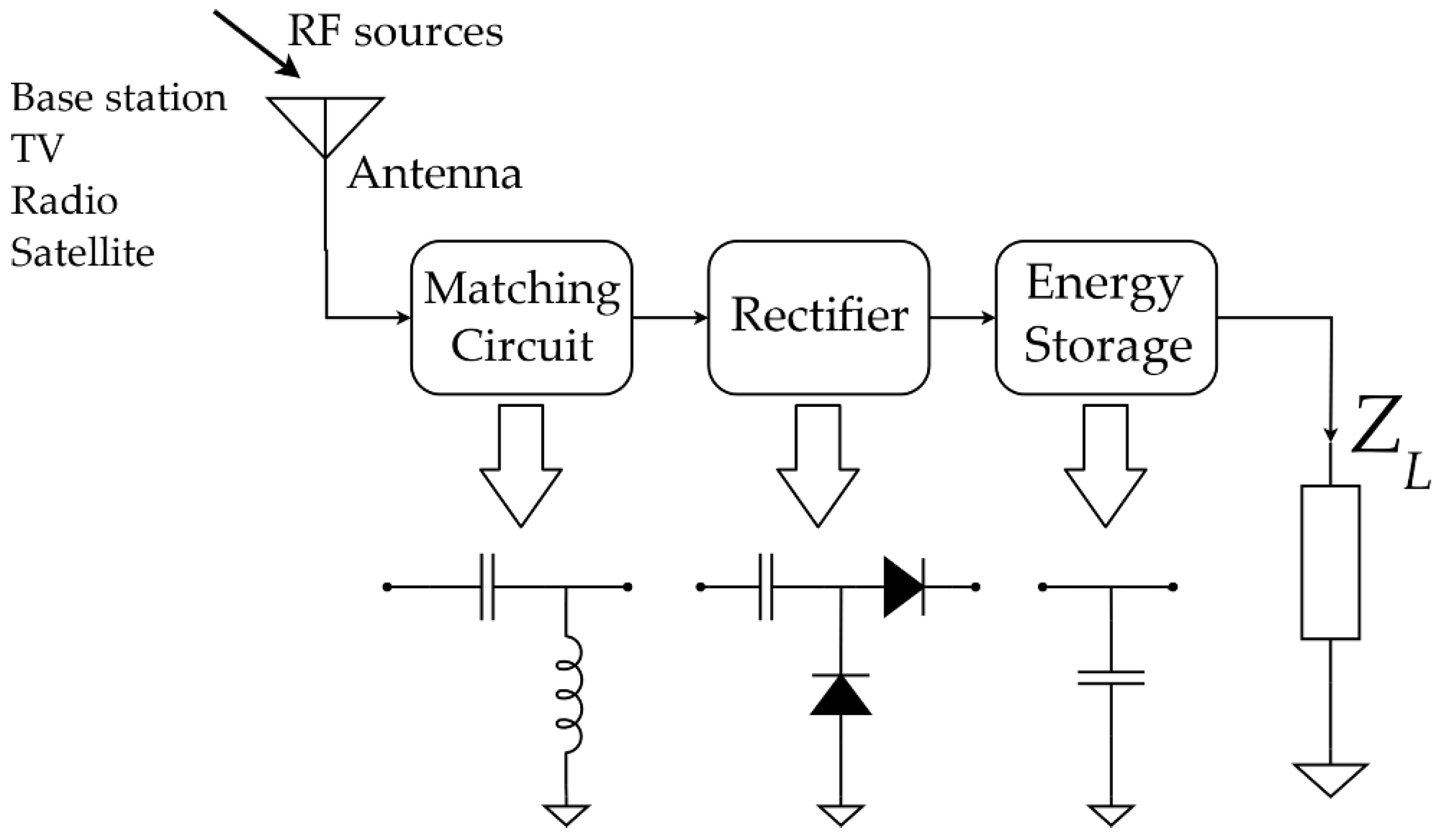
Figure 1. General block scheme of an RF Energy Harvesting device.
Jlpea 10 00011 g001
Figure 2. Non-linear power transferring efficiency of conceived rectifier for different load values (with a matched impedance on source port).
Jlpea 10 00011 g002
Figure 3. (a) Ideal schematic of the low-power device (LPD); (b) ideal schematic of the high-power device (HPD).
Jlpea 10 00011 g003
Figure 4. HPD input impedance (real and imaginary part) plotted on a Smith chart for input power levels from −25 to +20 dBm at 1 dBm steps (impedances are normalized to 50 Ω, which is the same as the input antenna) at a frequency of 915 MHz; it has been matched for an input power level of 10 dBm in order to get maximum efficiency for that value.
Jlpea 10 00011 g004
Figure 5. Low-power Device (a) and High-power device (b) realized circuits.
Jlpea 10 00011 g005
Figure 6. Simulated efficiency of the two systems both with ideal (a) and commercial components (b).
Jlpea 10 00011 g006
Figure 7. P2110 blocks diagram. With DSET unconnected, VCAP and DOUT are connected [21].
Jlpea 10 00011 g007
Figure 8. Experimental efficiency for all three systems at 850 MHz (a) and 915 MHz (b) using an RF power generator as a power source.
Jlpea 10 00011 g008
Figure 9. Outdoor free-space testbench to evaluate the performance of the proposed EH (Energy Harvesting) system and the commercial PB2110, on a matched equivalent resistive load.
Jlpea 10 00011 g009
Table 1. Value and model of used lumped elements for the LPD design.
ComponentValueModel
L147 nH08CS470
L256 nHLQW15AN56NJ00
C10.3 pFGJM1555C1HR30WB01
C20.3 pFGJM1555C1HR30WB01
Cout220 nFGRM36Y5V224Z10
Table 2. Value and model of used lumped elements for the HPD design.
ComponentValueModel
L318 nHLQW15AN18NH00
L44.7 nHLQW15AN4N7C00
C31.3 pFGJM1555C1H1R3WB01
Cout220 nFGRM36Y5V224Z10
Table 3. Measured voltage on P2110 and HPD for several distances.
Distance [m]P2110 Voltage [V]HPD Voltage [V]
0.252.04013.450
0.501.9809.300
0.751.9185.680
1.001.8924.680
1.501.8142.700
2.001.8102.110
2.501.8302.770
3.001.6001.990
4.000.2520.331
6.800.7200.900
8.000.8500.870
10.000.7300.740
15.000.1340.256
20.000.0020.075
22.000.0000.050