Abstract
PH measurements are widely used in agriculture, biomedical engineering, the food industry, environmental studies, etc. Several healthcare and biomedical research studies have reported that all aqueous samples have their pH tested at some point in their lifecycle for evaluation of the diagnosis of diseases or susceptibility, wound healing, cellular internalization, etc. The ion-sensitive field effect transistor (ISFET) is capable of pH measurements. Such use of the ISFET has become popular, as it allows sensing, preprocessing, and computational circuitry to be encapsulated on a single chip, enabling miniaturization and portability. However, the extracted data from the sensor have been affected by the variation of the temperature. This paper presents a new integrated circuit that can enhance the immunity of ion-sensitive field effect transistors (ISFET) against the temperature. To achieve this purpose, the considered ISFET macro model is analyzed and validated with experimental data. Moreover, we investigate the temperature dependency on the voltage-current (I-V). Accordingly, an improved conditioning circuit is designed in order to reduce the temperature sensitivity on the measured pH values of the ISFET sensor. The numerical validation results show that the developed solution accurately compensates the temperature variation on the measured pH values at low power consumption.
1. Introduction
The ion-sensitive field-effect transistors (ISFETs) sensor has played a major role in enabling the fabrication of fully integrated CMOS-based chemical sensing systems. This has allowed several new application areas, with the most promising fields being ion imaging and full genome sequencing. However, the data from this sensor is strongly affected by the variation of the temperature. ISFET is a chemical sensitive microsensor that is based on the field effect transistor, which was invented by Bergveld in the 1970s [1].
The detection principle (shown in Figure 1) of the ISFET sensor mechanism is centered on the charge adsorption at the solid ion interface between the electrolyte and the layer that contains the hydroxyl groups [2]. The assembly of hydroxyls can give or accept a proton. As a result of this process, a double layer capacity is generated with a potential variation that in its turn has an impact on the threshold voltage of the transistor according to the H+ ion concentration (i.e., pH) [2]. Moreover, ISFET is a compact sensor that enables a fast pH measurement.
Figure 1.
3D representation of a 6 × 8 ion-sensitive field effect transistor (ISFET) array.
However, this type of sensor is strongly affected by the temperature variation. Therefore, several researchers [3,4,5,6,7] have proposed various temperature compensation systems such as the proper choice of a biasing current for a thermal working point to reduce the ISFET’s temperature dependency [4]. Hence, the use of a junction diode Zener [4] for temperature compensation on a single ISFET sensor, the employment of an ISFET with a differential configuration (use of a differential amplifier) [8] that increases the immunity against temperature variation, or the combination of attenuators and a differential amplifier alongside with Caprio’s quad [7] were used in order to enhance the temperature stability. The trend of the recent works is set on ISFET sensor arrays [9,10,11,12,13], but most of these researches are focused on the wearable and thermoelectrically powered system [11] and on achieving very high accuracy and a small settling time [10]. They also focused on system-on-chip for real-time ion imaging [13], but most of them did not focus on the temperature effect on the response of the sensor and did not give a robust solution to reduce it. From these approaches, it can be noticed that the temperature dependency is studied at a particular or in a narrow range.
For a wide range of pH values, the temperature compensation becomes more difficult, since the temperature’s coefficient of an electrochemical device is a function of the pH value [14]. Moreover, the ISFET’s temperature dependency tends to exhibit a random behavior [15,16,17]. The straight-line-based temperature compensation limits its scope when dealing with the actual nonlinear temperature characteristic of ISFET’s device at different values. Furthermore, the temperature dependency of measuring a circuit also introduces additional temperature influence on the measured data. As a result, the ease of combining the temperature compensation circuit, the efficiency of the compensation technique, the circuit sensitivity, as well as the circuit simplicity with respect to body effects became the key design considerations in an integrated circuit design. Respectively, it is particularly challenging for ISFETs to work in an environment where the required task is to measure different pH ranges alongside different temperature values [18,19]. Nevertheless, the conventional means used in the signal processing of ISFETs, in particular the elementary current-voltage conversion circuits, do not reach optimal performance since they are sensitive to light variations and temperature especially when we use a sensor array (spread of the error that is related to temperature). In this study, it is important to understand the temperature behavior of an ISFET from a foundation work alongside research of a robust ISFET interface circuit combined with an improved temperature compensation technique. In view of the above problems, an improved ISFET interface circuit with a simple structure is proposed. This is in conjunction with the investigation of an improved dynamic biasing temperature compensation method. The latter is concerned with the arrangement of numerical iteration and mutual compensation in ISFET’s MOS transconductance characteristics. This results in almost zero temperature coefficients at any pH value. This enables the ISFET’s interface circuit to measure simultaneously the correct values of pH at any temperature. In this work, we investigate the temperature’s influence on the ISFET. Then, we propose a new integrated circuit, which is capable of reducing the temperature dependency and is applicable for systems such as sensor arrays. Then, we present a new demonstration of temperature compensation using the differential setup. Many researchers have reported several ISFET/reference field effect transistor (ReFET) topologies [20,21,22,23,24,25], and the first circuit that used ISFET/ReFET was introduced by Bergveld [20]. In this work, we present a new circuit based on differential measurement (ISFET/ReFET) operating in a weak inversion regime, and we demonstrate with a simple manner (mathematically) the temperature compensation using the ISFET/ReFET topology.
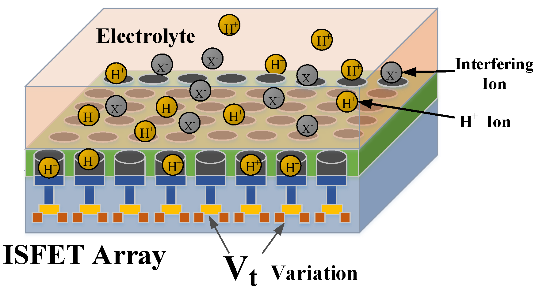
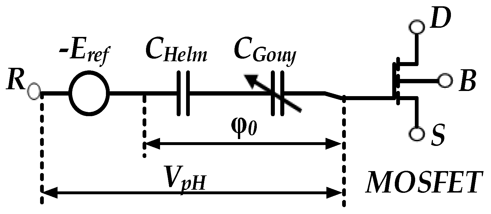
2. ISFET Macro Model
The considered ISFET macro model that captures the ISFET sensor current voltage (I-V) characteristic behavior is under temperature variation and based on the model developed under PSPICE [26,27]. The ISFET response to the ion is demonstrated by site binding theory, which gives a complete description of the ISFET behavior when combined with the Gouy–Chapman–Stern model and MOSFET physics [26]. As a consequence, a set of equations has been drawn up in order to study the sensitivity of the sensor and its dependence according to the physicochemical parameters of the ISFET. Subsequently, the SPICE macro model considers the ISFET sensor as two uncoupled stages: an electrochemical stage that represents the interface electrolyte–insulator modeled by site binding theory, along with an electronic stage, which is modeled by MOSFET. The considered equivalent electrical circuit of the ISFET macro model is shown in Figure 2.
Figure 2.
Equivalent electrical circuit of the ISFET structure.
Where R is the reference electrode, D is the drain, S is the electrolyte–insulation source, B is the substrate, and refers to the potential of the electrolyte–insulation interface. The expression of can be written as follows:
where is the potential applied to the reference electrode, is the electrostatic potential, which is directly proportional to pH and temperature, is the Boltzmann constant, is the absolute temperature, is the pH-zero point of charge, is the electron charge, and is the corrective parameter for pH–ISFET, which ranges between 0 and 1. The electrochemical properties of the insulating surface were combined with the nonlinear current-voltage (I-V) MOSFET, resulting in an expression of the threshold voltage of the ISFET, including terms derived from the MOSFET theory as well as terms of an electrochemical nature [26]:
where is the fermi potential of a semiconductor, is the charge density per surface unit at the insulator/semiconductor interface, is the charge density in the semiconductor depletion region, is the tension between the reference solution and the electrolyte, is the gate oxide capacity, and is the interface potential electrolyte/insulator dipole. It is worth noting that the potential is the only variable that depends on pH. Considering the weak inversion region of MOSFET, the I-V characteristic of ISFET can be written as follows:
where is a characteristic current, is the thermal voltage, and is the slope factor of the subthreshold. This mode of operation offers an opportunity to have a high intrinsic voltage gain and a low power processing.
2.1. Fabrication and Testing
The N-channel ISFET fabrication was carried out at the Semiconductor Physics Department, Research Institute of Microdevices (Kyiv, Ukraine). The gate dielectric is based on a sensitive film structure [28]. The sensor chip was attached to a Sital (fused silica) support and was bound to the aluminum conductors. The length of the canal is about 7 µm, and its width is 250 µm. To measure the current voltage ( characteristics of the ISFET, the substrate and the source are grounded and the source–drain voltage ( was maintained at 1 V. To measure the sensitivity of the ISFET sensor, we used three buffer solutions from pH = 3 to pH = 11. To investigate the reliability and stability of the pH sensor, we evaluated the temperature effects on the responses of the ISFET. Temperature can affect the characteristics of a sensor, the pH of the electrolyte, the potential of a reference electrode, and the measuring system. For latter changes, the temperature was kept constant inside the room. To keep the electrolyte, electrode, and ISFET at constant temperature, a heat-regulating loop including a temperature-sensing system and a heating system have been used. In addition, experimental results can only be compared validly to theory if the temperature during measurements is fixed. Figure 3 shows the experimental setup and the simulated equivalent circuit model implemented in the ADS based on modified SPICE model.
Figure 3.
(a) Experimental setup using the ISFET sensor, (b) ADS circuit simulation using the ISFET model.
For the experimental setup, we used a GW Instek SPS-606 generation for the variation; for measuring the variation, we used a Keithley 2400 Source Meter, and for , we used a simple DC generator. The results extracted from the simulation of the macro model were compared with the experimental recorded data, as shown in Figure 4.
Figure 4.
Model simulated in ADS versus experimental data.
The good agreement between the experimental and simulated data is confirmed by estimating Error (6), which is about 1.12% (worst case) for pH = 11.01 ⋲ [−1.8 V, −0.5 V]. For the next parts of this work, we used the validated macro model.
Moreover, Table 1 reports the technological parameters used for the ISFET macro model.
Table 1.
Technological parameters of the simulated macro model.
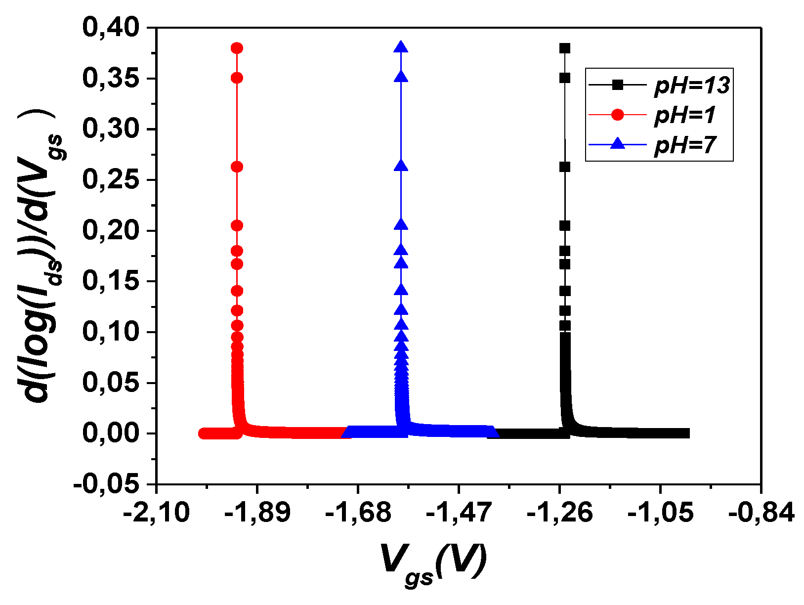
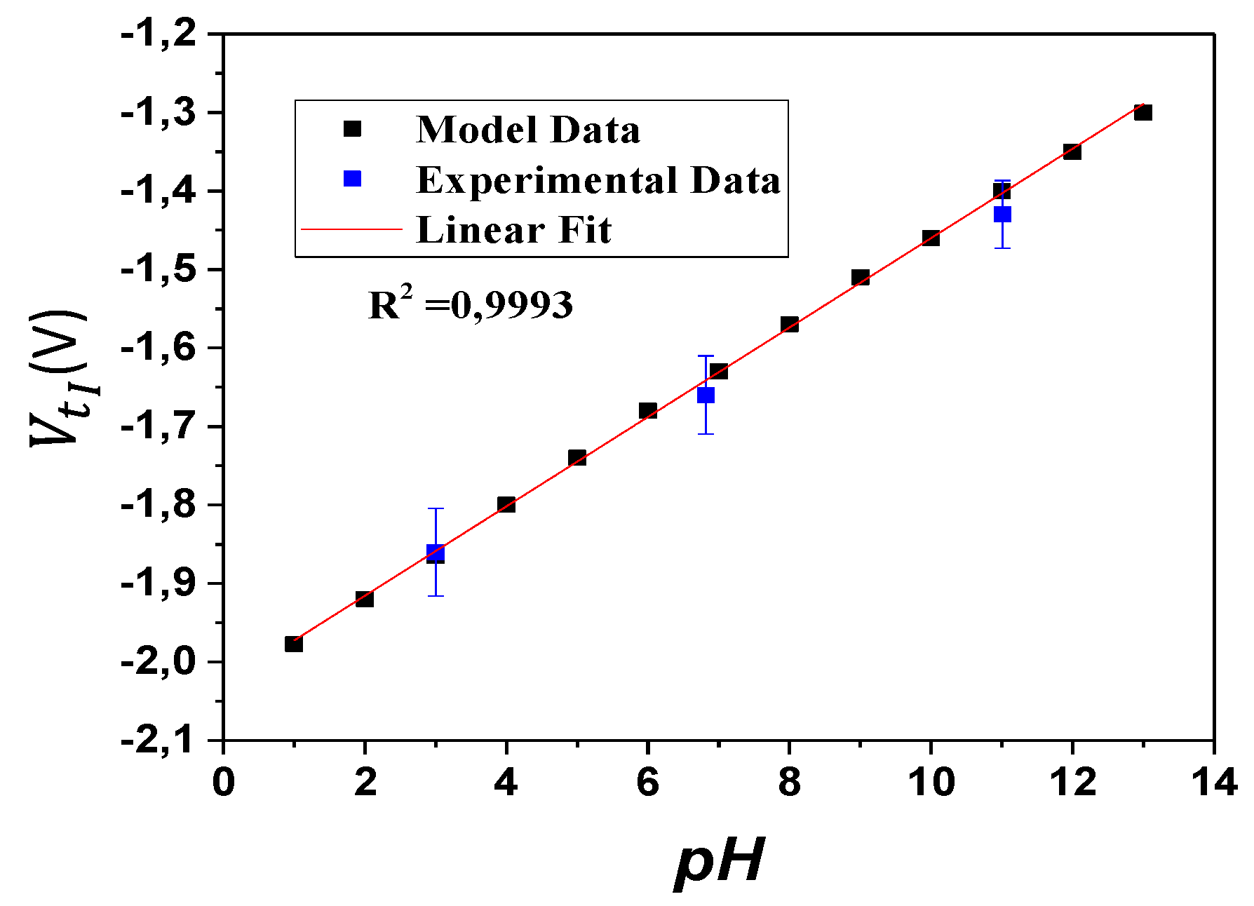
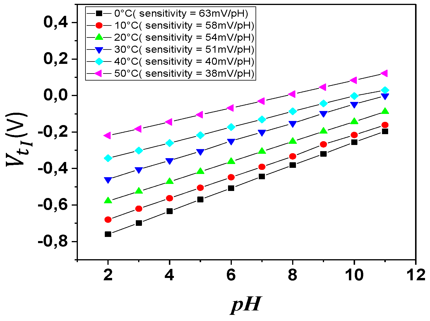
2.2. Sensor Sensitivity
In order to estimate the sensitivity of validated macro model, Figure 5 shows the variations of as a function of at constant = 1 V. The threshold voltage extraction method present in Figure 5 is inspired from the second derivative method [29], unless this technique can provide an exact threshold value more accurately. The proposed method enables other perspectives for the extraction of the technological parameters of the transistor.
Figure 5.
characteristics for different values of at T = 27 °C.
The is extracted for different pH values using the method of the first derivation. These values are then plotted on a graph as a function of the pH.
As seen in Figure 6, the determined sensitivity based on the ISFET macro model simulation (i.e., has approximately the same the sensitivity, which was calculated based on the experimental data (i.e., . In fact, the experimental ISFET characteristics were validated against the implemented macro model in order to accurately predict the pH values.
Figure 6.
Variation of of the sensor as a function of the pH (model and experimental data).
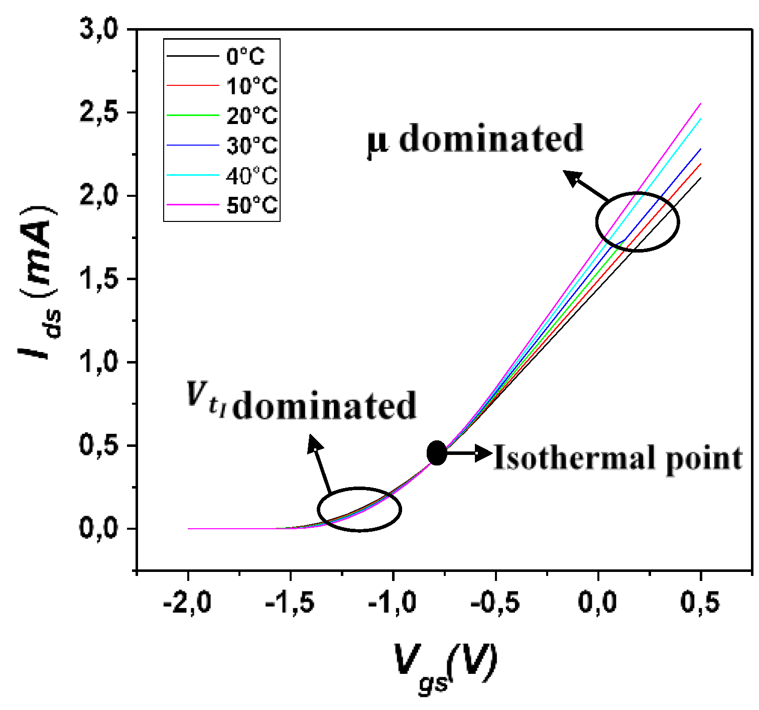
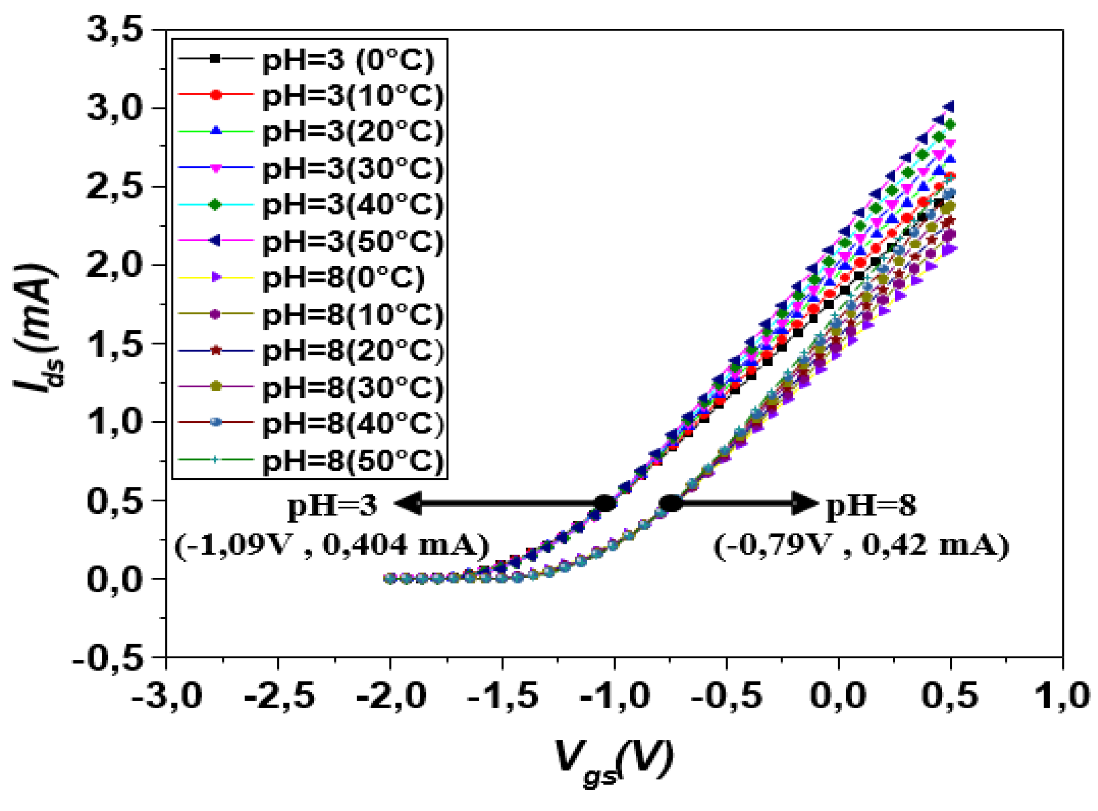
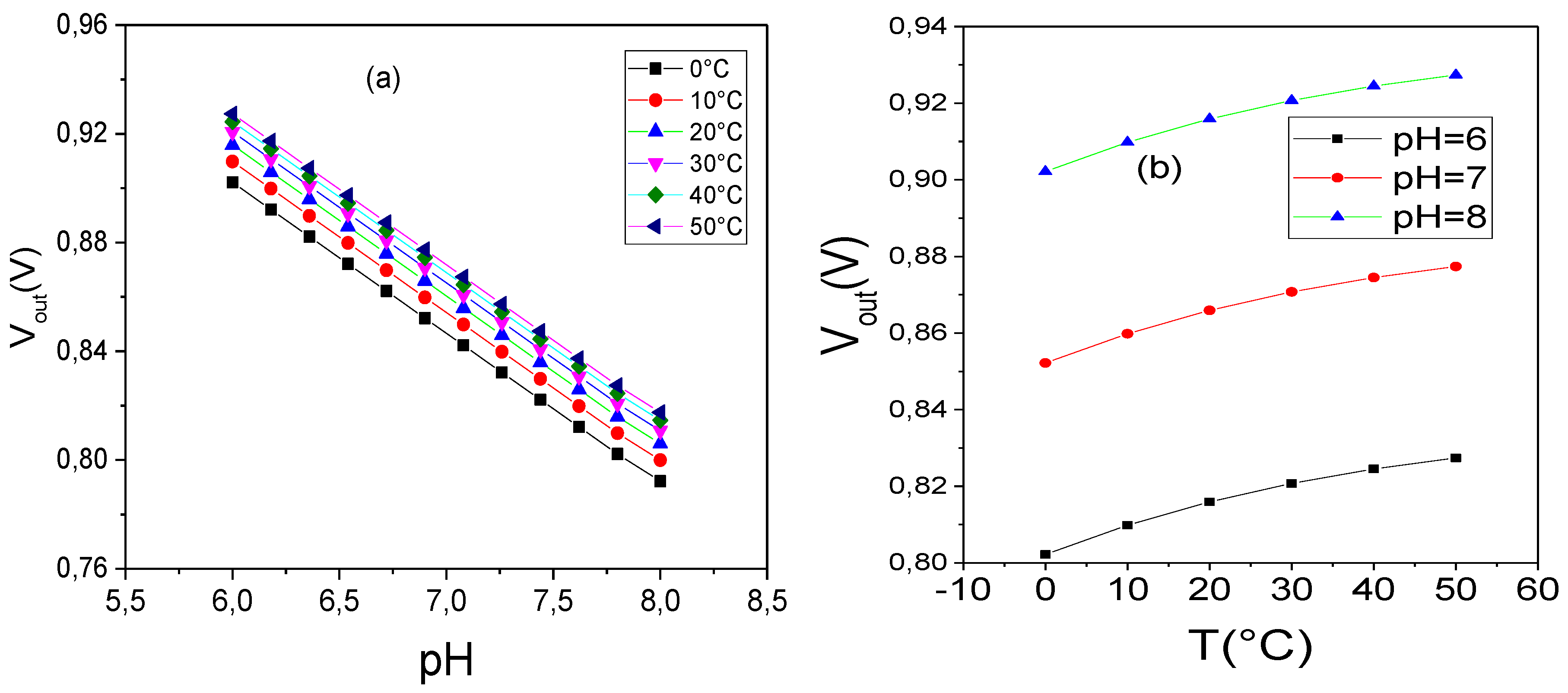
3. ISFET Temperature-Dependent Behavior
Several works have demonstrated that the ISFET electrochemical behavior shows a temperature dependency. In fact, the temperature variation affects the ISFET sensing circuit such as the reference electrode, electrolyte insulator potential, and MOSFET transistor. It can be expressed as:
where refers to the total temperature coefficient of ISFET. is the temperature coefficient of reference electrode , which has been reported by [22] with a standard value about 0.14 mV/°C. refers to the temperature coefficient of the interface potential electrolyte insulator. It has also been proven that is a function of pH value. It can differ from 0.54 mV to 1.1 mV as the pH increases from 4 to 10 [30]. The third item in (7) represents the coefficient of the temperature in MOS structure of ISFET. Based on the device physics, the principal parameters that are responsible for the temperature dependency of the MOSFET transistor are the mobility and threshold voltage. For any temperature, it can be modeled as follows:
where is the reference temperature and is a constant, with standard values between −1.9 and −2.2, depending on the doping concentrations of silicon. refers to the temperature coefficient of the threshold voltage, which is usually between −0.5 mV/°C and −3 mV/°C.
Analysis of the Temperature Effect on the ISFET Sensor
Studies by Jung-Lung CHIANG et al. [31] have shown that ISFET has a high temperature dependency, which leads to a pH measurement inaccuracy, so it is very important to study the temperature behavior of ISFETs and determine relevant methods to improve their temperature stability.
It is worth noting that by analyzing Figure 7, the drain current of the ISFET macro model varies considerably with the temperature. It deteriorates with an increase in temperature. This behavior is dominated by two phenomena: the degradation of the mobility and the shift of the threshold voltage , which result in the offset of the gate-source voltage below and above the isothermal point, respectively.
Figure 7.
curves of the ISFET sensor at temperatures between 0 and 50 °C.
For [−2 V, −0.75 V], we notice an offset of the threshold voltage above the isothermal point, which results in an increase of this later when the temperature increases.
For the degradation of the mobility is observed underneath the isothermal point. In fact, the temperature dependence of of the mobility significantly increases with the temperature [32].
The curvatures of Figure 8 are almost similar to the plots of Figure 7, but the only difference is shown by the dislocation of the isothermal point for the pH values equal to 3 and 8 (both Figure 7 and Figure 8 are obtained from the simulation of ISFET macro model). The dislocation of the isothermal point causes a decrease of the drain-source current and an increase of the gate source voltage .
Figure 8.
curves of the ISFET sensor at a temperature between 0 and 50 °C with a step of 10 °C for pH = 3 and 8.
Figure 9 demonstrates the variation of the threshold voltage as a function of pH over a wide temperature range. The shifting of the threshold voltage also results in the degradation of the sensor sensitivity for high pH values when the temperature varies from 0 to 50 °C. From visual inspection, the sensitivity of the sensor linearly varies with respect to the temperature, which is reported in Table 2.
Figure 9.
pH sensitivity of the ISFET sensor measured for a temperature from 0 to 50 °C with a step of 10 °C.
Table 2.
Variation of the sensor’s sensitivity according to the temperature’s variation.
The presented data in Figure 10 were extracted from Figure 9, and present the traces of the threshold voltage for pH = 6, when the temperature varies from 0 to 50 °C. Figure 10 also illustrates the dependence of the ISFET sensor on the temperature about 10 mV/°C (nearly 20% of sensitivity is affected by temperature).
Figure 10.
Threshold voltage as a function of temperature.
In cases where we have a sensor array (6 × 8 ISFETs), the noise generated by the temperature can distort any measurement. Therefore, it is necessary to add a complimentary circuit in order to reduce the temperature effect. The next section presents the proposed conditioning circuit that is capable of limiting the temperature dependency of the ISFET microsensor.
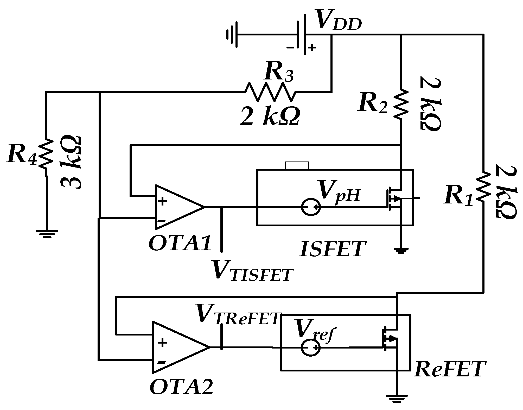
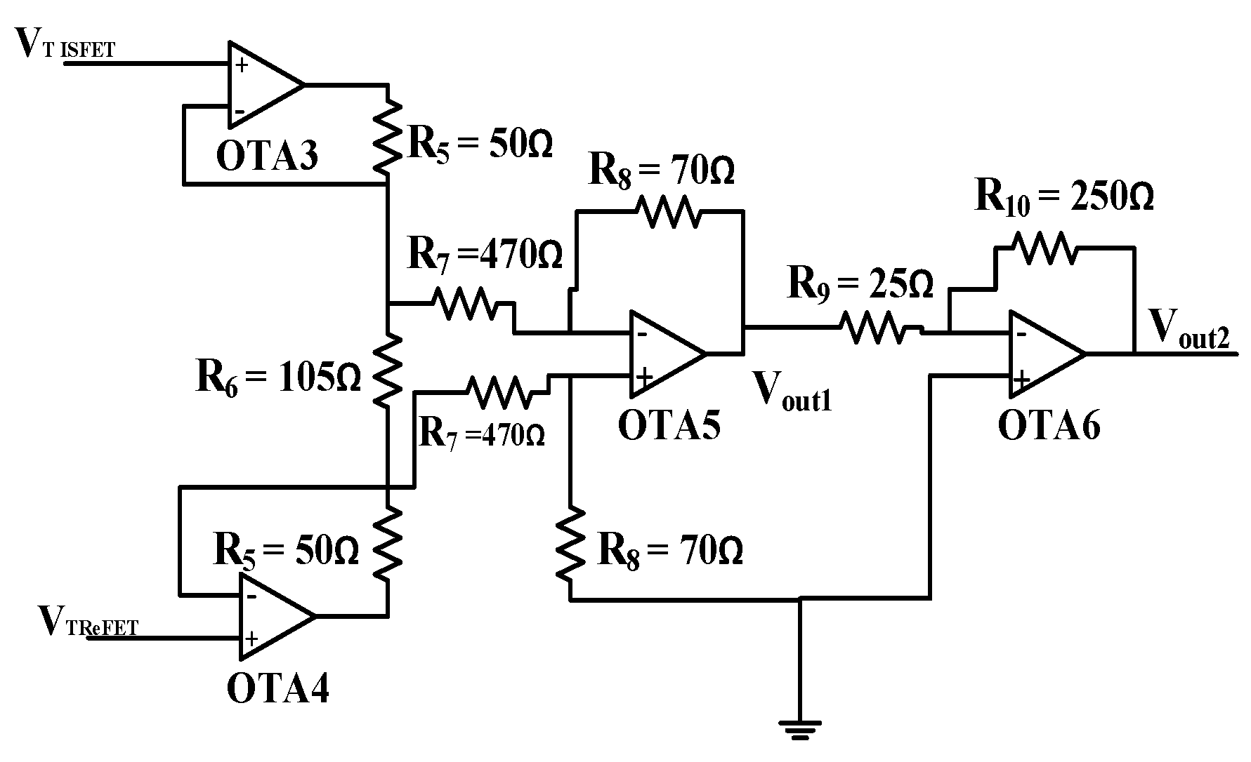
4. Proposed Temperature Compensation Circuit
This section analyzes the conditioning circuit architecture. The differential ISFET-based pH measurement is shown in Figure 11 and Figure 12. In fact, the ISFET sensor is used in a conjunction that is sensitive to a specific species (such as H+) and a reference field effect transistor (ReFET), which is insensitive to this species. ReFET was introduced to minimize the drift effects and the noise on the measurement. Both sensors must have the same electrical and chemical characteristics. A ReFET would experience a similar condition as an ISFET except the chance of responding to an occurring chemical reaction [33]. The ISFET/ReFET topology can be implemented in two configurations. The first configuration is to fabricate a REFET similar to ISFET but with a different membrane [2]. The second configuration is to make the REFET/ ISFET completely similar, but insulated and exposed to another analyst where no reaction may happen [34]. However, in addition to the DC offset problem that may bias the ISFET and REFET out of the active region causing the circuit to stack to the power-ground rail, the gate drain capacitance may distort the sensor response. The drain node is unmaintained, and it cannot follow the gate. Hence, with the Miller effects, the gain between the drain and the gate terminals of the deferential topology cause the appearance of the decoupling capacitors on the floating gate, and this may distort the signal. Nevertheless, to overcome the random DC offset, most of the ISFETs require a calibration of the reference electrode; ISFET/ReFET topology may also require more calibration between the ISFET and the reference FET, which makes it a little bit complicated for implementation in the ISFET arrays [2,35]. To overcome these limitations, the presented circuit in Figure 11 presents a solution for ISFET/ReFET topology. The feedback made by the amplifiers (OTA 1 and OTA 2) can control the calibration of the reference electrode to overcome the DC offset and make it easier the implementation of the ReFET/ISFET for the deferential measurement.
Figure 11.
Differential measurement interface based on ISFET/reference field effect transistor (ReFET).
Figure 12.
(a) Variation of as a function of pH for different temperatures, (b) variation of as a function of the temperature.
The circuit shown in Figure 11 is the one proposed by Irena [36], but the two weak power amplifier types AD8542 were replaced by the operational transconductance amplifier (OTA). The circuit was designed using ADS in TSMC 0.18 µm CMOS process technology. Indeed, all the components shown in Figure 11 are temperature dependent. The power consumption for each OTA is around 8 . Thanks to the feedback made by the two OTAs, this circuit can accurately control the temperature dependence.
The voltage that is applied to the negative inputs of the amplifiers OTA1 and OTA2 is formed by the voltage divider (), and is written as follows:
This constant voltage depends only on the power supply and is considered constant. The drain-source current in the branch of the resistor is written as follows:
where is from Equations (5) and (11), and the gate voltage of the sensor is deduced as follows:
We notice from Equation (12) that varies with the threshold voltage, i.e., with the electrochemical potential of the solution and the temperature. For the circuit (Figure 12), we assumed that the threshold voltage of this transistor was with and corresponding respectively to the theoretical threshold voltage of the transistor and the electrochemical potential of the solution. The gate voltage becomes as follows:
The DC simulation results of the circuit depicted in Figure 11 are shown in Figure 12. Figure 12a,b present respectively the variation of the output signal versus the input signal and the variation of versus the temperature variation for a range from 0 to 50 °C. Indeed, the SPICE models for each component of the circuit were used, and all the components are dependent on the temperature. According to Figure 12a, the output voltage is a linear function of . This circuit has a temperature drift of approximately 2 mV/°C, as shown in Figure 12b, where is considerably affected by the temperature. For pH sensitivity characterization, we worked under a pH range from 6 to 8. When we chose this measurement range, we were aware that for biomedical applications such as pH measurement and acidity monitoring of saliva, blood, urine, and intestinal fluids, a pH range of 6 to 8 would be sufficient [37,38,39].
4.1. Low-Power and Temperature Drift ISFET Compensation Circuit
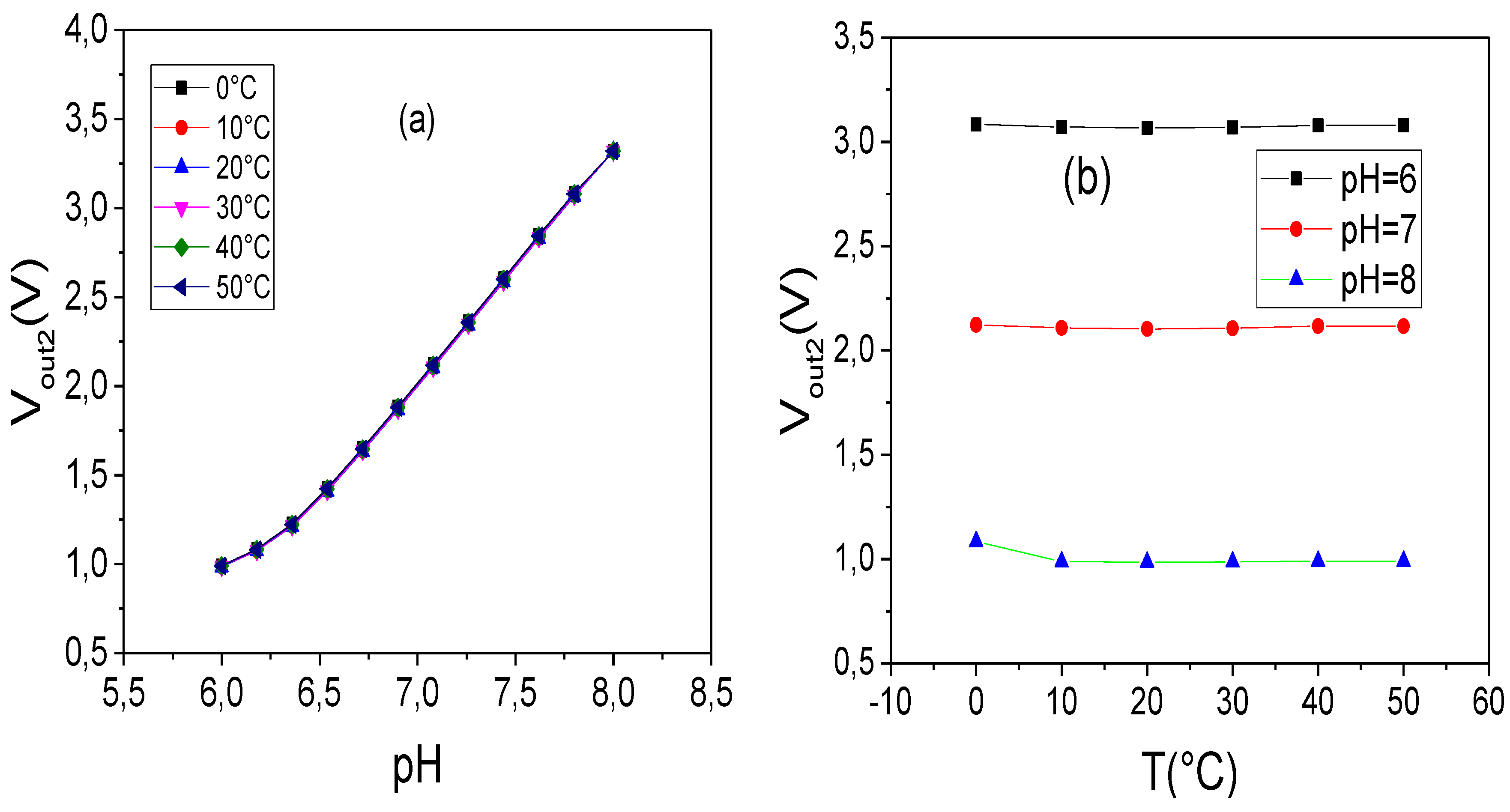
In order to improve immunity against temperature and increase the overall sensitivity, we propose an improvement circuit technique, which is presented in Figure 13. An instrumentation amplifier put on cascode with an inverter amplifier composes this circuit. The circuits presented in Figure 11 and Figure 13 present two pixels in an ISFET array.
Figure 13.
Operational transconductance amplifier (OTA)-based instrumentation amplifier for an ISFET temperature compensation circuit.
The instrumentation amplifier circuit increases the immunity against the temperature by an infinite common mode rejection ratio (CMRR) [40,41,42]. Therefore, the output signal is assumed to be not affected by the common noise or temperature:
As shown in Equation (14), is proportional to both resistance and thresholds, while the unified temperature-dependent threshold voltage of ISFET in any value can be written as follows [43]:
where is a coefficient with a value range between 0 and 1. The resistance could also be expected to increase with temperature. An intuitive approach to temperature dependence leads one to expect a fractional change in the resistance that is proportional to the temperature change:
where and are the resistance at temperature and (e.g., 27 °C), respectively. stands for the temperature coefficient, which depends on the resistance material. Equation (14) becomes as follows:
where refers to the pH value measured by the ReFET. According to Equation (17) and since the ISFET and ReFET have the same technological parameters, we can neglect the and the temperature coefficient of the threshold voltage and assume that the resistances , and have the same material; then, Equation (17) becomes:
Equation (18) illustrates the effectiveness of the proposed circuit for temperature reduction, since the two terms and are neglected. In addition, the thermal voltage will always be present, because it is related to the MOSFET structure and cannot be neglected. Before the proposed circuit, the temperature coefficient of the threshold voltage and the significantly affect the output voltage. Then, the temperature coefficient can be obtained as follows:
For = 4 and = 9.2, Equation (19) varies between V/°C and 14.03 V/°C for Therefore, we can assume that the temperature has no significant effect on the output voltage. The estimated temperature coefficient for pH = 6 is about 9.43 V/°C.
Figure 14a shows the variation of the output voltage as a function of the voltage for different temperatures ranging from 0 to 50 °C, while Figure 14b presents the dependence of on the temperature. Figure 14b shows that a 10 °C increase in the temperature results in a decrease of of the overall system output voltage , and subsequently, the coefficient of the temperature drift in this circuit becomes in the order of /°C. Here, we note very well the effectiveness of the instrumentation amplifier as a function of the temperature compensation. In addition, we notice that there is concordance between the mathematical demonstration and the simulation results in terms of a temperature coefficient. Here, we can assume that presented the Equations (18) and (19) can predict the temperature coefficient of ISFET/ReFET topology. Hence, the variation of the output voltage cannot exploit it easily, so we added an inverter amplifier to amplify the output voltage . Figure 15 shows the output voltage variation (Figure 15a) as a function of the input voltage for different temperature values.
Figure 14.
(a) Variation of the output voltage as a function of for different temperatures, (b) variation of as a function of the temperature.
Figure 15.
(a) Variation of the output voltage as a function of for different temperatures, (b) variation of as a function of the temperature.
The resolution found in this circuit is of the order of 324 mV/pH. This circuit has an in–out ratio about 6. As shown in Figure 15b, the proposed circuit has a temperature drift of about 3 V/°C in pH = 6 for a range of 0 to 50 °C, which is insignificant compared to the ISFET without the conditioning circuit (10 V/°C). We should note that all the components of the circuit present in Figure 11 and Figure 13 are dependent on temperature. This circuit has an estimated power consumption in the order of 1.8 .
4.2. Discussion
As it shows from the figures and results above that, the presented circuit undeniably represents an efficient and robust solution for biochemical reaction sensing. Target applications can include diagnostics based on DNA detection. Thanks to the possibilities for ion detection, this presented circuit will offer great opportunities in the field of lab-on-chip design. Table 3 compares this work with a previous work in terms of temperature compensation.
Table 3.
Comparative study for temperature compensation.
Table 4 presents a comparative study with other work for overall sensitivity.
Table 4.
Comparative study for overall sensitivity.
Table 4 shows that the proposed circuit has a low temperature dependence compared to other works, and it shows that the temperature change has no significant effects on the output signal. In addition, we should note that in this work, we used ADS for the first time, and referring to Table 4, most of work used the HSPICE simulation tool. Thus, ADS will open a new perspective in signal processing for ISFET sensors. On the other hand, Table 4 illustrates the overall sensitivity; most of the published work that focused on the enhancement of the sensitivity did not focus on the temperature variation and must be addressed. Meanwhile, Table 3 and Table 4 give a characteristic comparison between the proposed circuit based on OTA and others works. Using TSMC 0.18 µm technology, the proposed circuit based on OTA with low power consumptions and ISFET/ReFET working in a weak inversion regime gives a robust solution to reduce the temperature dependency and enhance the overall sensitivity. The proposed circuit presents a prototype for any biosensor (MEMFET, BioFET, ChemFET).
5. Conclusions
The presented instrumentation with a new conditioning circuit technique has been developed to compensate for the temperature dependence and obtain a good in–out ratio of ISFET microsensors with an assurance of a low consumption. To check the validation of the new conditioning circuit, an ADS simulation of functionality for sensitivity was performed. The ADS macro model treats the ISFET as two isolated stages (an electrochemical stage and an electronic stage), which were presented. In the first step, we validated the macro model by comparing it with experimental values. Then, we investigated the temperature effect on the ISFET, and we showed that this sensor has a strong temperature dependency. After that, we used the validated macro model to develop a new circuit that is capable of staying stable at any temperature from 0 to 50 °C. We also demonstrated that the proposed circuit has a good accuracy to measure the concentration of the pH and guaranteeing at the same time a low consumption at any temperature for a range from 0 to 50 °C. Finally, comparative studies were made in terms of the overall sensitivity.
Author Contributions
Conceptualization, A.G. and W.D.; methodology, A.G.; software, W.D.; validation, A.G., W.D. and B.H.; formal analysis, A.G. and W.D.; investigation, M.B.A.; data curation, A.G.; writing—original draft preparation, A.G. and W.D.; writing—review and editing, A.G. and W.D.; supervision, B.H. and M.B.A. All authors have read and agreed to the published version of the manuscript.
Funding
This research received no external funding.
Conflicts of Interest
The authors declare no conflict of interest.
References
- Bergveld, P. Development, Operation, and Application of the Ion-Sensitive Field-Effect Transistor as a Tool for Electrophysiology. IEEE Trans. Biomed. Eng. 1972, BME-19, 342–351. [Google Scholar] [CrossRef] [PubMed]
- Bergveld, P. Thirty years of ISFETOLOGY: What happened in the past 30 years and what may happen in the next 30 years. Sens. Actuators B Chem. 2003, 88, 1–20. [Google Scholar] [CrossRef]
- Bhardwaj, R.; Sinha, S.; Sahu, N.; Majumder, S.; Narang, P.; Mukhiya, R. Modeling and simulation of temperature drift for ISFET-based pH sensor and its compensation through machine learning techniques. Int. J. Circuit Theory Appl. 2019, 47, 954–970. [Google Scholar] [CrossRef]
- Chung, W.-Y.; Lin, Y.-T.; Pijanowska, D.G.; Yang, C.-H.; Wang, M.-C.; Krzyskow, A.; Torbicz, W. New ISFET interface circuit design with temperature compensation. Microelectron. J. 2006, 37, 1105–1114. [Google Scholar] [CrossRef]
- Liu, T.; Chung, W.; Cruz, F.R.G.; Tsai, Y.; Pijanowska, D.G.; Torbicz, W.; Grabiec, P.B.; Jaroszewicz, B. VTH-Extractors Based Readout Circuit of ISFET with Temperature Compensation. In Proceedings of the 2007 IEEE Conference on Electron Devices and Solid-State Circuits, Tainan, Taiwan, 20–22 December 2007; pp. 901–904. [Google Scholar]
- Chen, D.Y.; Chan, P.K. An Intelligent ISFET Sensory System With Temperature and Drift Compensation for Long-Term Monitoring. IEEE Sens. J. 2008, 8, 1948–1959. [Google Scholar] [CrossRef]
- Naimi, S.E.; Hajji, B.; Humenyuk, I.; Launay, J.; Temple-Boyer, P. Temperature influence on pH-ISFET sensor operating in weak and moderate inversion regime: Model and circuitry. Sens. Actuators B Chem. 2014, 202, 1019–1027. [Google Scholar] [CrossRef]
- Chung, W.Y.; Yang, C.H.; Pijanowska, D.G.; Grabiec, P.B.; Torbicz, W. ISFET performance enhancement by using the improved circuit techniques. Sens. Actuators B Chem. 2006, 113, 555–562. [Google Scholar] [CrossRef]
- Liu, Y.; Al-Ahdal, A.; Georgiou, P.; Toumazou, C. Minimal readout scheme for ISFET sensing arrays based on pulse width modulation. Electron. Lett. 2012, 48, 548–549. [Google Scholar] [CrossRef]
- Hu, Y.; Georgiou, P. An Automatic Gain Control System for ISFET Array Compensation. IEEE Trans. Circuits Syst. I Regul. Pap. 2016, 63, 1511–1520. [Google Scholar] [CrossRef]
- Douthwaite, M.; Koutsos, E.; Yates, D.C.; Mitcheson, P.D.; Georgiou, P. A Thermally Powered ISFET Array for On-Body pH Measurement. IEEE Trans. Biomed. Circuits Syst. 2017, 11, 1324–1334. [Google Scholar] [CrossRef]
- Huang, X.; Yu, H.; Liu, X.; Jiang, Y.; Yan, M.; Wu, D. A Dual-Mode Large-Arrayed CMOS ISFET Sensor for Accurate and High-Throughput pH Sensing in Biomedical Diagnosis. IEEE Trans. Biomed. Eng. 2015, 62, 2224–2233. [Google Scholar] [CrossRef] [PubMed]
- Hu, Y.; Moser, N.; Georgiou, P. A 32 × 32 ISFET Chemical Sensing Array with Integrated Trapped Charge and Gain Compensation. IEEE Sens. J. 2017, 17, 5276–5284. [Google Scholar] [CrossRef]
- Barabash, P.R.; Cobbold, R.S.C.; Wlodarski, W.B. Analysis of the threshold voltage and its temperature dependence in electrolyte-insulator-semiconductor field-effect transistors (EISFET’s). IEEE Trans. Electron Devices 1987, 34, 1271–1282. [Google Scholar] [CrossRef]
- Sardarinejad, A.; Maurya, D.K.; Khaled, M.; Alameh, K. Temperature effects on the performance of RuO2 thin-film pH sensor. Sens. Actuators A Phys. 2015, 233, 414–421. [Google Scholar] [CrossRef]
- Hemmink, G.J.M.; Weusten, B.L.A.M.; Oors, J.; Bredenoord, A.J.; Timmer, R.; Smout, A.J.P.M. Ambulatory oesophageal pH monitoring: A comparison between antimony, ISFET, and glass pH electrodes. Eur. J. Gastroenterol. Hepatol. 2010, 22, 572–577. [Google Scholar] [CrossRef]
- Moser, N.; Lande, T.S.; Toumazou, C.; Georgiou, P. ISFETs in CMOS and Emergent Trends in Instrumentation: A Review. IEEE Sens. J. 2016, 16, 6496–6514. [Google Scholar] [CrossRef]
- Niigata, K.; Narano, K.; Maeda, Y.; Ao, J.-P. Temperature dependence of sensing characteristics of a pH sensor fabricated on AlGaN/GaN heterostructure. Jpn. J. Appl. Phys. 2014, 53, 11RD01. [Google Scholar] [CrossRef]
- Khanna, V.K. Remedial and adaptive solutions of ISFET non-ideal behaviour. Sens. Rev. 2013, 33, 228–237. [Google Scholar] [CrossRef]
- Bergveld, P.; Van Den Berg, A.; Van Der Wal, P.D.; Skowronska-Ptasinska, M.; Sudhölter, E.J.R.; Reinhoudt, D.N. How electrical and chemical requirements for refets may coincide. Sens. Actuators 1989, 18, 309–327. [Google Scholar] [CrossRef]
- Errachid, A.; Bausells, J.; Jaffrezic-Renault, N. A simple REFET for pH detection in differential mode. Sens. Actuators B Chem. 1999, 60, 43–48. [Google Scholar] [CrossRef]
- Bretschneider, F.; de Weille, J. Chapter 3—Electronic Devices. In Introduction to Electrophysiological Methods and Instrumentation, 2nd ed.; Bretschneider, F., de Weille, J., Eds.; Academic Press: Cambridge, MA, USA, 2019; pp. 39–75. [Google Scholar]
- Morgenshtein, A.; Sudakov-Boreysha, L.; Dinnar, U.; Jakobson, C.G.; Nemirovsky, Y. Wheatstone-Bridge readout interface for ISFET/REFET applications. Sens. Actuators B Chem. 2004, 98, 18–27. [Google Scholar] [CrossRef]
- Morgenshtein, A.; Sudakov-Boreysha, L.; Dinnar, U.; Jakobson, C.G.; Nemirovsky, Y. CMOS readout circuitry for ISFET microsystems. Sens. Actuators B Chem. 2004, 97, 122–131. [Google Scholar] [CrossRef]
- Wong, H.; White, M.H. A CMOS-integrated ‘ISFET-operational amplifier’ chemical sensor employing differential sensing. IEEE Trans. Electron Devices 1989, 36, 479–487. [Google Scholar] [CrossRef]
- Martinoia, S.; Massobrio, G. A behavioral macromodel of the ISFET in SPICE. Sens. Actuators B Chem. 2000, 62, 182–189. [Google Scholar] [CrossRef]
- Daniel, M.; Szermer, M.; Napieralski, A.; Charlot, J.J. CHEMFET modelling for hardware description languages. In Proceedings of the Modern Problems of Radio Engineering, Telecommunications and Computer Science (IEEE Cat. No.02EX542), Lviv-Slavsko, Ukraine, 18–23 February 2002; pp. 338–341. [Google Scholar]
- Hendji, A.M.N.; Jaffrezic-Renault, N.; Martelet, C.; Clechet, P.; Shlu’ga, A.A.; Strikha, V.I.; Netchiporuk, L.I.; Soldatkin, A.P.; Wlodarski, W.B. Sensitive detection of pesticides using a differential ISFET-based system with immobilized cholinesterases. Anal. Chim. Acta 1993, 281, 3–11. [Google Scholar] [CrossRef]
- Ortiz-Conde, A.; García Sánchez, F.J.; Liou, J.J.; Cerdeira, A.; Estrada, M.; Yue, Y. A review of recent MOSFET threshold voltage extraction methods. Microelectron. Reliab. 2002, 42, 583–596. [Google Scholar] [CrossRef]
- Martinoia, S.; Lorenzelli, L.; Massobrio, G.; Conci, P.; Lui, A. Temperature effects on the ISFET behaviour: Simulations and measurements. Sens. Actuators B Chem. 1998, 50, 60–68. [Google Scholar] [CrossRef]
- Chiang, J.L.; Chou, J.C.; Chen, Y.C. Study on light and temperature properties of AlN pH-Ion-sensitive field-effect transistor devices. Jpn. J. Appl. Phys. Part 1 Regul. Pap. Short Notes Rev. Pap. 2005, 44, 4831–4837. [Google Scholar] [CrossRef]
- Goel, A.K.; Tan, T.H. High-temperature and self-heating effects in fully depleted SOI MOSFETs. Microelectron. J. 2006, 37, 963–975. [Google Scholar] [CrossRef]
- Mlika, R.; Ouada, H.B.; Kalfat, R.; Gamoudi, G.; Mhenni, F.; Jaffrezic-Renault, N. Thin sensitive organic membranes on selective iron-ion sensors. Synth. Met. 1997, 90, 239–243. [Google Scholar] [CrossRef]
- Garner, D.M.; Bai, H.; Georgiou, P.; Constandinou, T.G.; Reed, S.; Shepherd, L.M.; Wong, W.; Lim, K.T.; Toumazou, C. A multichannel DNA SoC for rapid point-of-care gene detection. In Proceedings of the 2010 IEEE International Solid-State Circuits Conference (ISSCC), San Francisco, CA, USA, 7–11 February 2010; pp. 492–493. [Google Scholar]
- Sohbati, M. Circuits and Systems for DNA Detection by Ion-Sensitive Field Effect Transistor. Ph.D. Thesis, Imperial College London, London, UK, 2014. [Google Scholar]
- Humenyuk, I. Développement des Microcapteurs ChemFETs Pour L’analyse de L’eau. Ph.D. Thesis, Institut National des Sciences Appliquées de Toulouse, Toulouse, France, 2005. [Google Scholar]
- Mellins, R.B.; Levine, O.R.; Wigger, H.J.; Leidy, G.; Curnen, E.C. Experimental menigococcemia: Model of overwhelming infection in unanesthetized monkeys. J. Appl. Physiol. 1972, 32, 309–314. [Google Scholar] [CrossRef] [PubMed]
- Evans, D.F.; Pye, G.; Bramley, R.; Clark, A.G.; Dyson, T.J.; Hardcastle, J.D. Measurement of gastrointestinal pH profiles in normal ambulant human subjects. Gut 1988, 29, 1035. [Google Scholar] [CrossRef] [PubMed]
- Baliga, S.; Muglikar, S.; Kale, R. Salivary pH: A diagnostic biomarker. J. Indian Soc. Periodontol. 2013, 17, 461–465. [Google Scholar] [CrossRef] [PubMed]
- Safari, L.; Minaei, S. A novel COA-based electronically adjustable current-mode instrumentation amplifier topology. AEU Int. J. Electron. Commun. 2017, 82, 285–293. [Google Scholar] [CrossRef]
- Eldeeb, M.A.; Ghallab, Y.H.; Ismail, Y.; El-Ghitani, H. A 0.4-V Miniature CMOS Current Mode Instrumentation Amplifier. IEEE Trans. Circuits Syst. II Express Briefs 2018, 65, 261–265. [Google Scholar] [CrossRef]
- Butti, F.; Piotto, M.; Bruschi, P. A Chopper Instrumentation Amplifier With Input Resistance Boosting by Means of Synchronous Dynamic Element Matching. IEEE Trans. Circuits Syst. I Regul. Pap. 2017, 64, 753–764. [Google Scholar] [CrossRef]
- Chan, P.K.; Chen, D.Y. A CMOS ISFET interface circuit with dynamic current temperature compensation technique. IEEE Trans. Circuits Syst. I Regul. Pap. 2007, 54, 119–129. [Google Scholar] [CrossRef]
- Ma, D.; Georgiou, P.; Toumazou, C. A weak inversion ISFET current mirror for differential bio-sensing. In Proceedings of the 2016 IEEE Biomedical Circuits and Systems Conference (BioCAS), Shanghai, China, 17–19 October 2016; pp. 42–45. [Google Scholar]
- Harrak, A.; Naimi, S.E. Design and simulation of a CMOS compatible pH-ISFET readout circuit, with low thermal sensitivity. In Proceedings of the 2017 International Conference on Electrical and Information Technologies (ICEIT), Rabat, Morocco, 15–18 November 2017; pp. 1–6. [Google Scholar]
- Xiwei, H.; Fei, W.; Jing, G.; Mei, Y.; Hao, Y.; Kiat Seng, Y. A 64 × 64 1200 fps CMOS ion-image sensor with suppressed fixed-pattern-noise for accurate high-throughput DNA sequencing. In Proceedings of the 2014 Symposium on VLSI Circuits Digest of Technical Papers, Honolulu, HI, USA, 10–13 June 2014; pp. 1–2. [Google Scholar]
- Park, J.-K.; Jang, H.-J.; Park, J.-T.; Cho, W.-J. SOI dual-gate ISFET with variable oxide capacitance and channel thickness. Solid State Electron. 2014, 97, 2–7. [Google Scholar] [CrossRef]
- Jiang, Y.; Liu, X.; Dang, T.C.; Huang, X.; Feng, H.; Zhang, Q.; Yu, H. A High-Sensitivity Potentiometric 65-nm CMOS ISFET Sensor for Rapid E. coli Screening. IEEE Trans. Biomed. Circuits Syst. 2018, 12, 402–415. [Google Scholar] [CrossRef]
© 2020 by the authors. Licensee MDPI, Basel, Switzerland. This article is an open access article distributed under the terms and conditions of the Creative Commons Attribution (CC BY) license (http://creativecommons.org/licenses/by/4.0/).