1. Introduction
Human-following autonomous mobile robots (AMRs) are increasingly being applied to service, logistics, healthcare, and human-assistive mobility environments, where robots are required to move safely while maintaining a desired relative position with respect to a target person or object [
1,
2,
3]. Unlike conventional mobile robots operating along predefined routes in structured environments, human-following AMRs must continuously recognize a moving target, perceive surrounding obstacles, generate feasible local paths, and execute motion commands in real time. Therefore, the design of a compute-efficient robotic mobility system that integrates perception, planning, and control is an important issue for practical deployment.
To track a specific human or object effectively, AMRs commonly employ multiple sensing modalities, including cameras, Light Detection and Ranging (LiDAR), Ultra-Wideband (UWB), and Tether Follow Sensors (TFS) [
4,
5,
6,
7]. Camera-based recognition can provide visual information for identifying a target, while LiDAR can support obstacle detection and local environmental mapping. UWB and TFS can also be used to estimate the relative position of a target with respect to the robot. Although these sensing modalities improve recognition reliability, they also increase the computational burden of the overall system, particularly when target recognition, obstacle perception, local path planning, and motion control must be executed simultaneously on low-cost embedded hardware.
Path planning is a core function of AMR navigation and is generally divided into global and local planning. Global path planning algorithms, such as Dijkstra’s algorithm, A*, and D*, compute routes using map information [
8,
9,
10]. These approaches are effective for route-level planning but can become computationally expensive when frequent replanning is required in dynamic environments. In contrast, local path planning methods, such as the Rapidly exploring Random Tree (RRT) and the Dynamic Window Approach (DWA), are designed to generate short-horizon collision-free motions based on real-time sensor information [
11,
12]. Among them, DWA is widely used because it directly considers the robot’s feasible velocity space and obstacle clearance. However, conventional DWA repeatedly evaluates densely sampled motion candidates at every planning cycle. This repeated evaluation can increase computation time and reduce real-time responsiveness when additional perception and control modules are concurrently running on embedded processors.
To address this limitation, this paper introduces a Hierarchical Dynamic Window Approach (HDWA) as the local planning module of a multimodal human-following robotic mobility system. HDWA uses direct-path feasibility to determine whether coarse direction selection and detailed path refinement are required, thereby avoiding unnecessary candidate evaluations under simple environmental conditions. Its effectiveness was evaluated on a low-cost human-following micro-mobility robot.
The main contributions of this paper are summarized as follows:
A compute-efficient human-following robotic mobility system is presented by integrating multimodal target recognition, LiDAR-based obstacle perception, hierarchical local planning, and low-level motion control into a unified perception–planning–control architecture.
A Hierarchical Dynamic Window Approach (HDWA) is proposed that uses direct-path feasibility as a computation gate and activates the Direction and Detail Dynamic Window States only when obstacle avoidance is required, thereby reducing redundant candidate evaluations.
Experimental validation is conducted on a low-cost embedded micro-mobility robot platform, demonstrating a 30.8–92.3% reduction in candidate-evaluation workload, shorter avoidance trajectories, and improved average driving speed and elapsed motion time compared with conventional DWA.
The remainder of this paper is organized as follows.
Section 2 reviews related studies on human-following mobile robots and local path planning methods.
Section 3 describes the proposed human-following robotic mobility system architecture.
Section 4 presents the proposed HDWA algorithm and its hierarchical planning procedure.
Section 5 describes the experimental setup and performance evaluation. Finally,
Section 6 concludes the paper and presents future research directions.
2. Related Work
Human-following mobile robots require the integration of target recognition, obstacle perception, local path planning, and motion control to maintain a desired relative position with respect to a moving target. Unlike general-purpose autonomous mobile robots that navigate toward fixed goal points, human-following robots must continuously update the target position and generate safe motion commands in response to both target movement and surrounding obstacles. Therefore, path planning for human-following robots should be considered not only as an algorithmic problem, but also as a system-level problem involving sensing, computation, and real-time control.
Path planning algorithms have been widely studied in various robotic and mobility domains, including autonomous mobile robots (AMRs), unmanned aerial vehicles (UAVs), and autonomous vehicles. These algorithms are essential for enabling safe, efficient, and collision-free navigation from an initial position to a target position [
13,
14]. The selection of an appropriate planning method depends on the robot’s geometry, kinematic constraints, environmental uncertainty, sensing capability, and computational resources. In particular, for human-following robots operating on embedded hardware, the computational load of the planner directly affects the responsiveness of the overall perception–planning–control system.
2.1. Human-Following Mobile Robots
Human-following robots have been studied for applications such as delivery assistance, logistics support, healthcare service, and human–robot interaction. These robots commonly use cameras, LiDAR, UWB, or wearable/tether-based sensors to estimate the relative position of the target and maintain a safe following distance [
1,
2,
3,
4,
5,
7]. Camera-based methods provide visual information for target identification, while LiDAR-based methods offer robust distance measurement and obstacle perception. UWB and TFS-based methods can estimate the relative position of a target with relatively low computational cost, although their performance depends on sensor attachment, communication reliability, or mechanical configuration.
Recent studies have extended human-following robots from simple target tracking toward integrated navigation in dynamic and human-populated environments. Eirale et al. provided a comprehensive review of recent human-following and guidance systems, emphasizing the integration of target perception, navigation, and human–robot interaction [
15]. Acosta-Amaya et al. presented a lightweight behavior-based control architecture for human following under limited computational resources [
16], while Plozza et al. integrated an embedded 2D LiDAR-based person tracker with a navigation framework for real-time operation in dynamic human environments [
17]. Nguyen et al. further incorporated human position, velocity, and personal-space information into a DWA-based planner using LiDAR and RGB-D sensing [
18]. These studies demonstrate that reliable human-following behavior requires the concurrent operation of target localization, obstacle and human perception, local planning, and motion control. However, executing these modules simultaneously on low-cost embedded processors can reduce system responsiveness, particularly when the local planner repeatedly evaluates unnecessary motion candidates. This limitation motivates the development of planning methods that reduce redundant computation while preserving target-following and obstacle-avoidance performance.
2.2. Global Path Planning
Path planning methods are generally categorized into global path planning and local path planning. Global path planning computes a route from a start point to a goal point using prior map information. Representative global planning algorithms include Dijkstra’s algorithm [
8], A* [
9], and D* [
10]. Dijkstra’s algorithm finds the shortest path by expanding graph nodes based on cumulative cost and guarantees an optimal solution for graphs with non-negative edge costs. However, its exhaustive search process can become inefficient as the map size increases.
The A* algorithm improves search efficiency by incorporating a heuristic function that guides the search toward the goal. Owing to its simplicity and effectiveness, A* has been widely used in robotic navigation. D* and its variants are also useful for replanning in partially known or changing environments. Nevertheless, global path planning methods generally rely on prebuilt maps or map updates, and their computational cost can increase when frequent replanning is required. In addition, map construction through methods such as Simultaneous Localization and Mapping (SLAM) can impose additional computational burdens on embedded robotic systems [
19,
20]. Therefore, global planning alone is insufficient for real-time human-following tasks in dynamic environments.
2.3. Local Path Planning
Local path planning generates short-horizon motion commands based on real-time sensor information and is therefore suitable for dynamic obstacle avoidance. Representative local planning methods include Rapidly exploring Random Trees (RRT) [
11] and the Dynamic Window Approach (DWA) [
12]. RRT incrementally explores the configuration space by sampling random points and extending tree branches toward unexplored regions. Although RRT can handle high-dimensional and non-holonomic planning problems, its stochastic nature may generate non-smooth paths, which can be undesirable for continuous human-following tasks.
DWA determines the optimal linear and angular velocities by evaluating candidate trajectories within the dynamically feasible velocity space of the robot. Since DWA considers the robot’s current velocity, acceleration limits, heading direction, and obstacle distance, it is widely used for real-time obstacle avoidance in mobile robots. However, conventional DWA evaluates a predefined set of sampled motion candidates at every planning cycle, regardless of whether obstacles actually interfere with the target-following path. This repeated evaluation can lead to unnecessary computation, especially when target recognition, LiDAR-based mapping, and control signal generation are executed concurrently.
Several studies have improved DWA to enhance adaptability, path optimality, or dynamic obstacle response. Dobrevski and Skocaj [
21] proposed an adaptive DWA that adjusts planning parameters according to environmental conditions. Other studies combined A* with DWA or integrated reinforcement learning techniques to improve global optimality and local responsiveness [
22,
23,
24,
25]. Although these approaches can improve navigation performance, many of them increase algorithmic complexity or assume sufficient computing resources. This can limit their applicability to low-cost human-following robots that must operate in real time on embedded hardware.
2.4. Resource-Aware Planning for Embedded Robotic Systems
For embedded robotic systems, planning performance should be evaluated not only in terms of path quality and obstacle-avoidance capability, but also in terms of computational feasibility. A local planner that generates smooth and safe trajectories may still be unsuitable if it consumes excessive processing time and consequently delays perception or control modules. This issue is particularly important for human-following robots, in which the target position changes continuously and the robot must respond promptly to both target motion and surrounding obstacles.
Recent studies have increasingly integrated target tracking, human-aware navigation, and local planning for operation in dynamic environments [
15,
16,
17,
18]. However, the concurrent execution of perception, planning, and control remains a practical challenge on low-cost embedded platforms with limited computational resources.
From a system-level perspective, the local planner should allocate computational effort according to environmental complexity. In obstacle-free situations, evaluating a large number of avoidance candidates is unnecessary. In contrast, when an obstacle interferes with the direct target-following path, additional evaluations are required to determine a safe avoidance direction. Therefore, a resource-aware planning structure should reduce redundant computation in simple situations while retaining detailed planning capability when obstacle avoidance is required.
Existing approaches address planning efficiency in different ways. Adaptive DWA modifies evaluation weights or planning parameters according to environmental conditions while retaining the candidate-evaluation procedure of the original DWA framework [
21]. Hybrid A*–DWA methods combine global path search with local dynamic obstacle avoidance and may additionally include path segmentation or smoothing stages [
22,
23,
25,
26]. Hierarchical planning methods reduce the search space by decomposing the environment into multiple regions and performing inter-regional and intra-regional searches [
27]. These methods improve adaptability, global path quality, or search scalability; however, their computational structures are mainly based on parameter adaptation, global–local planner integration, or map decomposition.
In contrast, the planning problem considered in this study requires a local planner that can avoid unnecessary candidate evaluation when the direct human-following path is not obstructed, while retaining detailed avoidance capability when an obstacle is present. Therefore, this study proposes a resource-aware HDWA that conditionally allocates trajectory-evaluation computation according to the surrounding obstacle conditions, without requiring an additional global planner or pre-segmented environmental map.
3. System Architecture of the Human-Following Micro-Mobility Robot
This section presents the system architecture of the proposed human-following micro-mobility robot and describes its recognition, planning, and control layers.
3.1. Overview
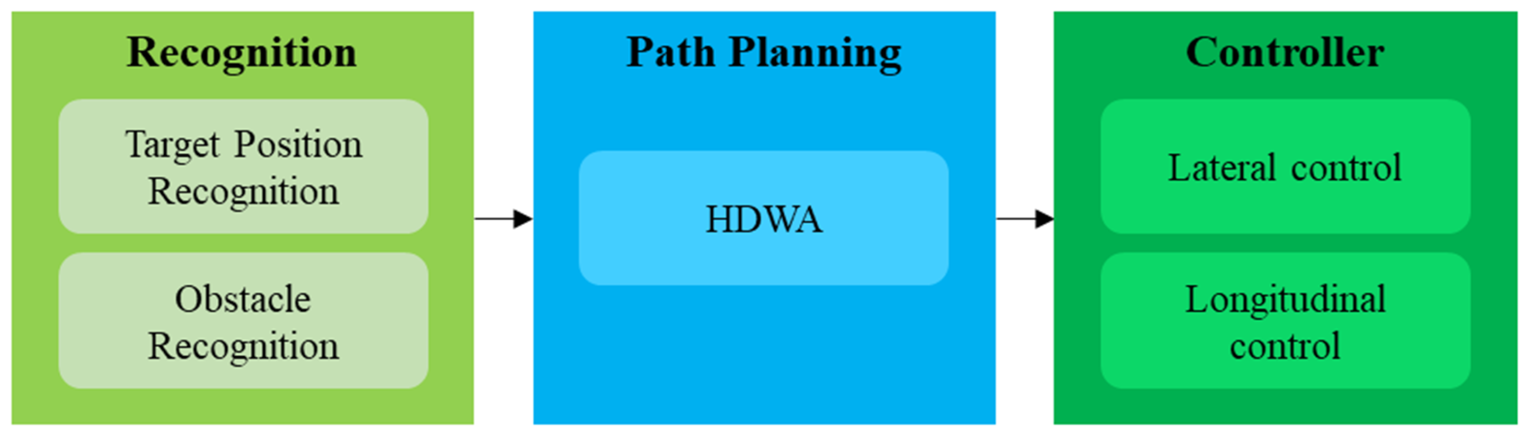
The proposed system consists of three core functional layers: recognition, path planning, and control, as illustrated in
Figure 1.
The proposed architecture is divided into the following three functional layers:
Recognition layer: This layer detects and tracks the target human while recognizing surrounding obstacles using RGB-D, TFS, and LiDAR sensor data.
Planning layer: This layer executes the proposed HDWA to generate a collision-free local goal based on the target position and obstacle map.
Control layer: This layer converts the planned local goal into motion commands by determining the linear and angular velocities required for stable target following.
This layered architecture supports stable target-following operation by coordinating target recognition, local planning, and motion control while reducing unnecessary candidate evaluations in the planning layer.
3.2. Recognition Layer
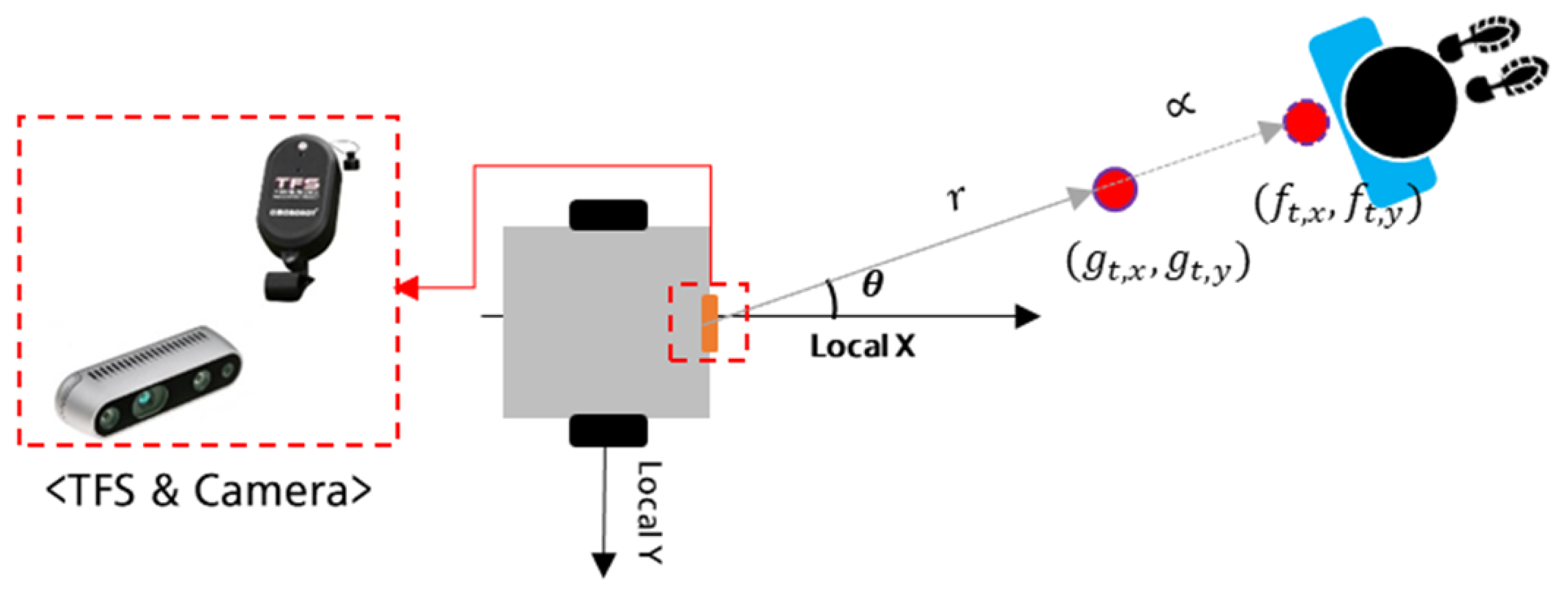
The recognition layer performs two main tasks: target recognition and obstacle perception. Target recognition estimates the relative position between the robot and the target, whereas obstacle perception identifies surrounding obstacles that may interfere with the target-following path. To achieve these tasks, the proposed system can employ multiple sensing modalities, including RGB-D vision, LiDAR, Ultra-Wideband (UWB), and Tether Follow Sensors (TFS), as shown in
Figure 2 [
24]. The selection of each sensor depends on the operating environment, target visibility, required distance accuracy, and computational constraints. The TFS was used as a low-computation alternative to camera-based target localization. In this study, the RGB-D camera and TFS were operated as separate target-tracking modalities, and the relative target position estimated by either method was provided to the same HDWA planner. The 2D LiDAR was independently used for obstacle perception and occupancy-grid generation. Therefore, the TFS was not intended to compensate for LiDAR or vision failures under challenging outdoor conditions. Rather, it was included to demonstrate that the proposed planning framework can operate with different target-localization inputs. The present experiments were conducted in structured indoor environments, and outdoor validation remains a topic for future work.
At time
t, the relative position of the target with respect to the follower robot is defined as
. When an RGB-D camera is used, the target position is detected from the RGB image through vision-based recognition, and the corresponding depth information is used to estimate the target position in the robot-centered coordinate frame [
4]. In contrast, TFS-based recognition measures the target’s relative distance and direction through a tether-based sensing mechanism [
6]. The estimated target position is then used as the input to the local planning layer.
To prevent collision with the target and ensure stable following behavior, the robot maintains a constant tracking margin
between itself and the target. The desired tracking point is denoted as
, which is calculated as follows:
where
and
. This formulation allows the robot to follow the target while maintaining a predefined safety distance.
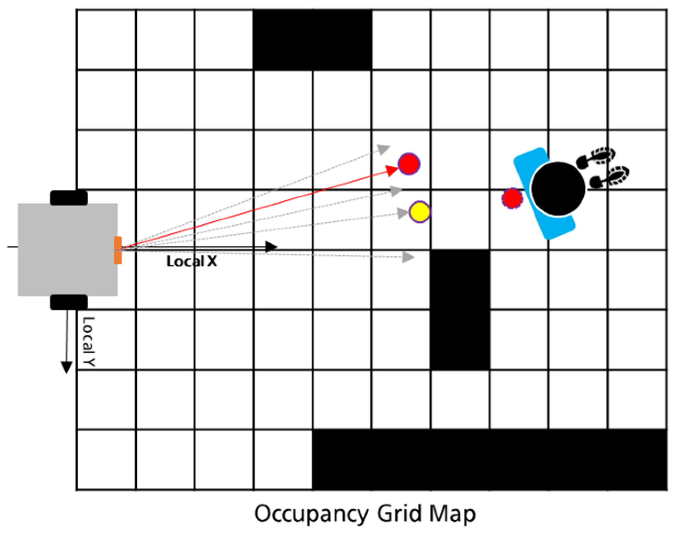
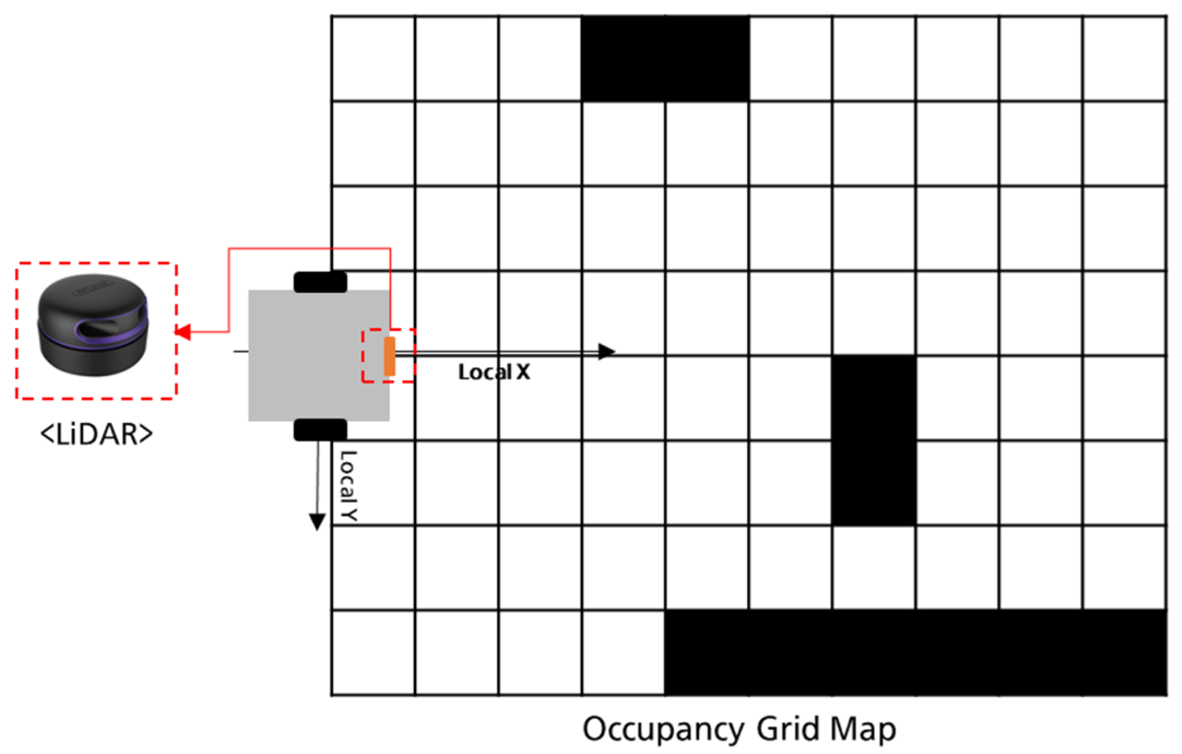
In addition to target recognition, obstacle perception is performed using LiDAR data. A two-dimensional occupancy grid map
is generated in real time, where each grid cell is assigned a value of 1 if it contains an obstacle and 0 otherwise. As shown in
Figure 3, LiDAR point cloud data are projected onto a 2D grid to identify obstacles around the robot. The generated occupancy grid map is then provided to the HDWA-based planning layer for collision-free local path generation.
3.3. Planning Layer
In the planning layer, the proposed HDWA computes a collision-free local goal that enables the robot to follow the target while avoiding surrounding obstacles. As shown in
Figure 4, HDWA determines the adjusted target position
, which serves as a locally feasible goal satisfying both target-following and obstacle-avoidance constraints.
Unlike conventional DWA, which evaluates sampled motion candidates at every planning cycle, HDWA hierarchically determines whether additional avoidance computation is required. The planning process is divided into three states: Movement, Direction, and Detail Dynamic Windows. This hierarchical structure reduces redundant trajectory evaluations in obstacle-free situations and performs more detailed path refinement only when obstacles interfere with the target-following path. Therefore, the planning layer contributes directly to the real-time feasibility of the overall human-following robotic system under embedded computing constraints. A detailed explanation of each state and its algorithmic structure is provided in
Section 4.
3.4. Control Layer
The control layer generates motion commands based on the local goal computed by the planning layer. Its role is to determine the linear and angular velocity commands required to reach the planned local goal while maintaining stable target-following behavior. In this study, the control layer consists of lateral control based on the Pure Pursuit concept and longitudinal control based on a proportional–integral–derivative (PID) controller.
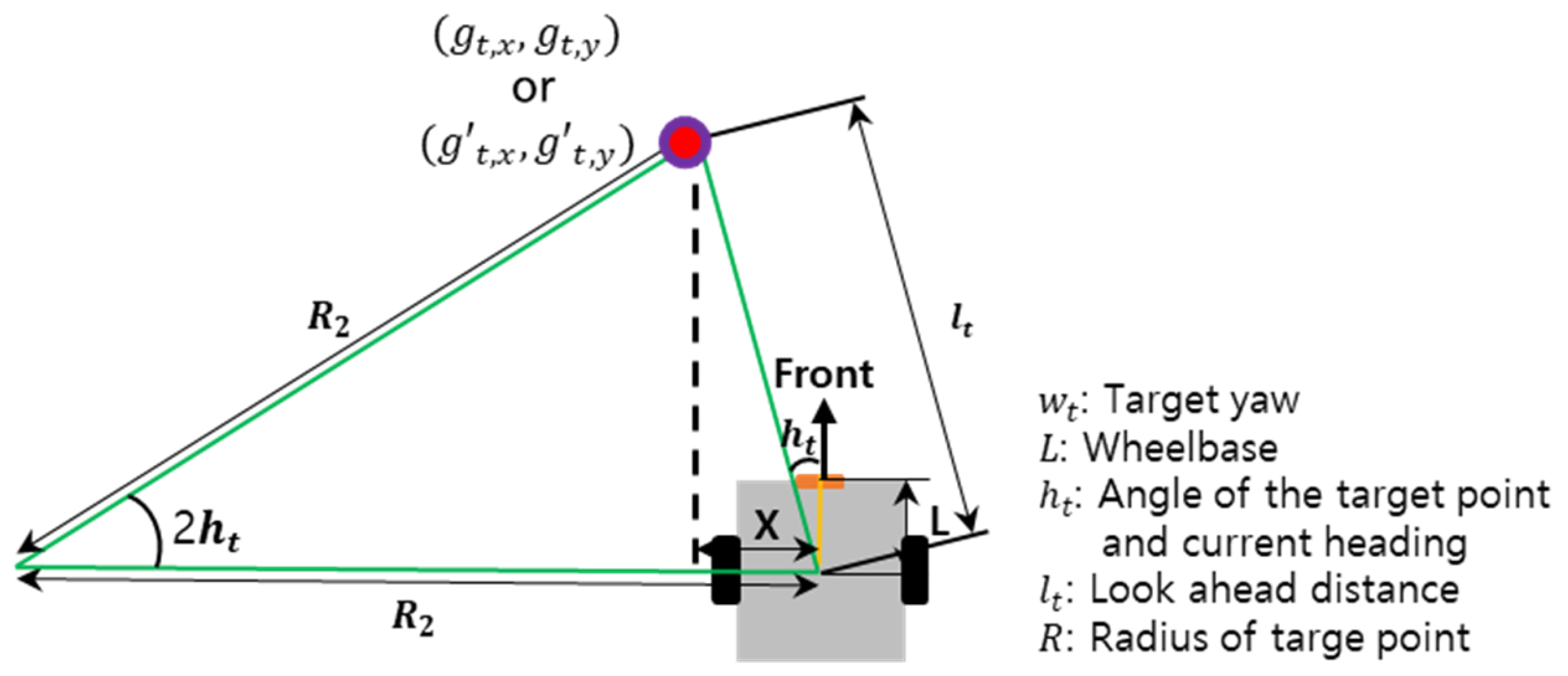
For lateral control, the heading angle between the robot and the planned local goal is used to determine the angular motion command. As shown in
Figure 5, the Pure Pursuit-based controller computes the required heading control command from the geometric relationship between the robot and the goal point
.
The target distance
and heading angle
are calculated based on the relative position of the planned local goal
as follows:
The heading control command
is then determined using the robot length parameter
L and the look-ahead distance
:
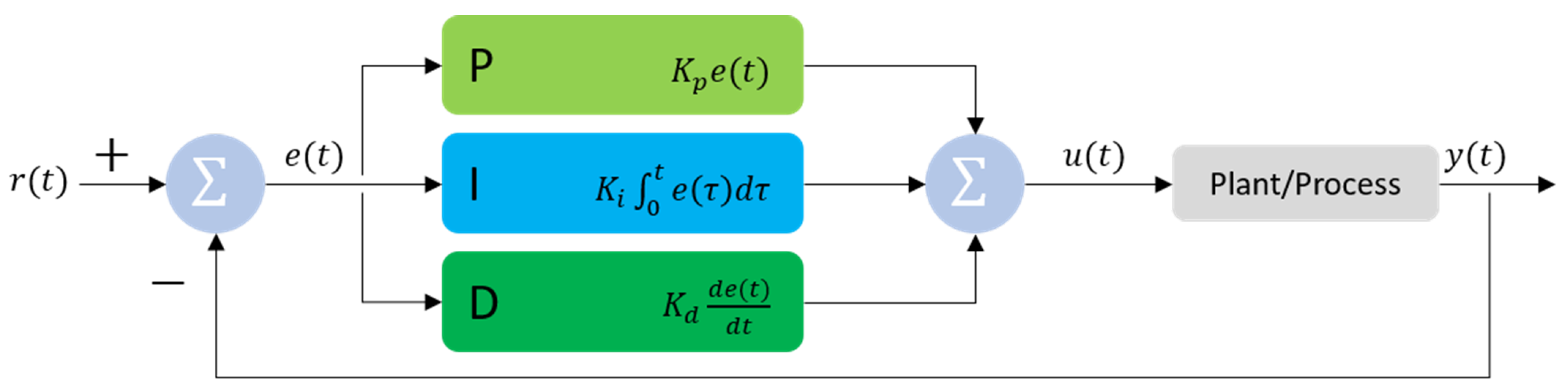
For longitudinal control, the linear velocity is adjusted according to the distance error between the robot and the desired following position. As shown in
Figure 6, a PID controller is used to stabilize the tracking distance and reduce sudden velocity changes. The main variables used in the PID controller are summarized in
Table 1.
The linear velocity command
is calculated as follows:
To prevent sudden acceleration, overshoot, and excessive approach toward the target, two safety regions are defined: a maximum distance region and a minimum distance region. The maximum distance region constrains excessive velocity increase when the target is far from the robot, whereas the minimum distance region prevents the robot from surpassing or colliding with the target. By combining the Pure Pursuit-based lateral controller and PID-based longitudinal controller, the robot can generate smooth and responsive tracking behavior in dynamic environments.
4. Hierarchical Dynamic Window Approach
The Hierarchical Dynamic Window Approach (HDWA) is proposed as the resource-aware local planning module of the human-following robotic mobility system. The objective of HDWA is to generate a feasible local goal that enables the robot to follow the target while avoiding obstacles with reduced computational load. In contrast to conventional DWA, which evaluates a predefined set of candidate trajectories at every planning cycle, and fixed multi-stage methods, which execute all search stages for each planning query, HDWA uses direct-path feasibility as a computation gate. Adaptive and A*–DWA methods primarily adjust evaluation parameters or introduce global-path guidance, whereas HDWA changes when additional candidate evaluation is performed: the Direction and Detail Dynamic Window States are activated only when the direct target-following path is blocked. Therefore, the main distinction of HDWA lies in the conditional allocation of candidate-evaluation computation according to obstacle conditions, rather than in the use of a hierarchical structure itself.
The overall process of HDWA consists of three hierarchical states, as shown in
Figure 7: Movement Dynamic Window State, Direction Dynamic Window State, and Detail Dynamic Window State. In the Movement Dynamic Window State, the robot first checks whether the desired tracking point can be reached without obstacle interference. If no obstacle is detected, the desired tracking point is directly used as the local goal, thereby avoiding unnecessary trajectory evaluation. If an obstacle is detected, the algorithm transitions to the Direction Dynamic Window State, where a coarse avoidance direction is selected from a set of candidate directions. Finally, the Detail Dynamic Window State refines the selected direction using finer angular sampling to generate a smoother and safer local goal.
4.1. Movement Dynamic Window State
The Movement Dynamic Window State determines whether obstacle avoidance computation is required. Its main purpose is to reduce unnecessary planning operations by checking whether the robot can move directly toward the desired tracking point without colliding with surrounding obstacles.
The desired tracking point is defined as
, which is obtained from the recognition layer. The occupancy grid map at time
t is denoted as
. The algorithm evaluates the line segment between the current robot position and
while considering the robot size. If all grid cells along this line segment are free, the adjusted local goal is set as
In this case, the robot can continue target-following motion without activating additional avoidance planning. If at least one occupied grid cell is detected along the movement direction, the algorithm transitions to the Direction Dynamic Window State.
4.2. Direction Dynamic Window State
When an obstacle blocks the direct path to the desired tracking point, the Direction Dynamic Window State performs coarse avoidance direction selection. In this state, candidate local goals are generated by applying a set of angular offsets around the direction of .
Let the polar representation of the desired tracking point be defined as
The
n-th candidate direction is generated using an angular offset
as follows:
where
denotes the
n-th candidate local goal in polar coordinates. The angular offsets are sampled at a relatively coarse resolution in this state to quickly determine a feasible avoidance direction with low computational cost.
Each candidate is evaluated using a cost function composed of a goal-following term and an obstacle-avoidance term:
where
penalizes deviation from the desired tracking point, and
penalizes proximity to occupied cells in the occupancy grid map. The weighting coefficients were fixed at
and
throughout the planning process. A larger weight was assigned to the obstacle-avoidance term to prioritize collision safety while retaining the target-following tendency through the goal term. The same coefficients were used in both the Direction and Detail Dynamic Window States without online adaptation. A lower cost indicates that the candidate better satisfies both target-following and obstacle-avoidance requirements.
The candidate with the minimum cost is selected as the coarse avoidance direction:
If all candidate directions are blocked or infeasible, the robot stops and maintains its current position as a temporary local goal to prevent collision.
4.3. Detail Dynamic Window State
The Detail Dynamic Window State refines the coarse direction selected in the previous state. While the Direction Dynamic Window State uses coarse angular sampling to reduce computation, the Detail Dynamic Window State applies finer angular offsets around the selected direction to improve path smoothness and obstacle clearance.
Let the selected coarse direction be represented by
. A refined candidate is generated using a small angular offset
as follows:
where
denotes the
k-th refined candidate local goal in polar coordinates. The refined candidates are evaluated using the same cost function defined in Equation (
8):
The final refined candidate is selected as
Finally, the selected refined candidate is converted from polar coordinates to Cartesian coordinates to obtain the adjusted local goal
:
The adjusted local goal is then delivered to the control layer for motion-command generation. Through this hierarchical process, HDWA reduces redundant trajectory evaluation in simple situations and performs detailed avoidance computation only when necessary. As a result, the proposed method improves the real-time feasibility of human-following mobile robots operating under embedded hardware constraints.
5. Experiments and Results
This section presents the experimental validation of the proposed human-following robotic mobility system. The experiments were designed to evaluate whether the proposed HDWA can reduce the candidate-evaluation workload of local planning while maintaining target-following and obstacle-avoidance performance on low-cost embedded hardware. The evaluation focuses on three aspects: the robot platform configuration, the experimental environment, and the comparative performance of the proposed HDWA against conventional planning methods.
5.1. Experimental Platform
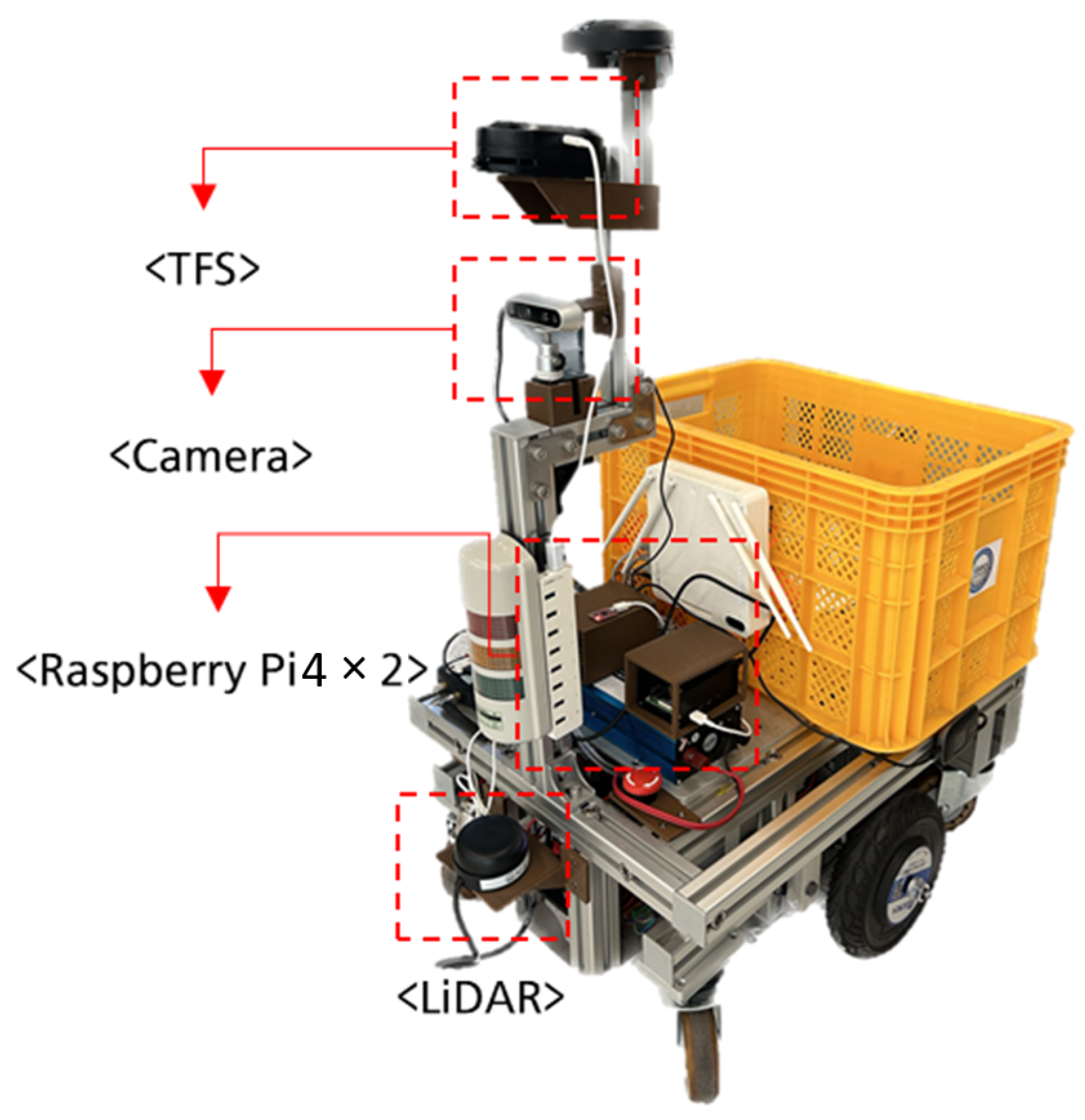
The micro-mobility robot used in the experiment is shown in
Figure 8. The drive motors were mounted at the center of both sides, and caster wheels were placed at the corners. This six-wheel configuration enables differential steering and compact rotation in narrow spaces. The motor system was designed to transport a payload of up to 250 kg and achieve a maximum speed of 7.5 km/h. The wheelbase and the length parameter
L used in the controller were both set to 0.2 m.
For target tracking, the robot used an RGB-D camera, Intel RealSense D435, and a Tether Follow Sensor (TFS) [
6]. The RGB-D camera was used for vision-based target recognition and distance estimation, while the TFS provided relative target information through a tether-based mechanism. For obstacle perception, a 2D LiDAR sensor, RPLiDAR, was used to acquire surrounding obstacle information. The LiDAR data were converted into a two-dimensional occupancy grid map for local obstacle avoidance.
Two Raspberry Pi 4 boards were used to separate the main processing tasks. One board handled robot control and LiDAR-based occupancy mapping, while the other processed camera input for vest-based target recognition and distance estimation. This configuration reflects the embedded computing constraints of the proposed system, where perception, planning, and control must be executed simultaneously with limited computational resources. The integrated sensing and control system was operated at a fixed update rate of 10 Hz. This update rate was determined by the LiDAR acquisition cycle and the motor-control period, rather than by the maximum execution rate of the local planner. Accordingly, a 100 ms interval was assigned to each perception–planning–control cycle. Target recognition, occupancy mapping, local planning, and motion control were executed concurrently across the two Raspberry Pi 4 boards described above.
5.2. Experimental Environment
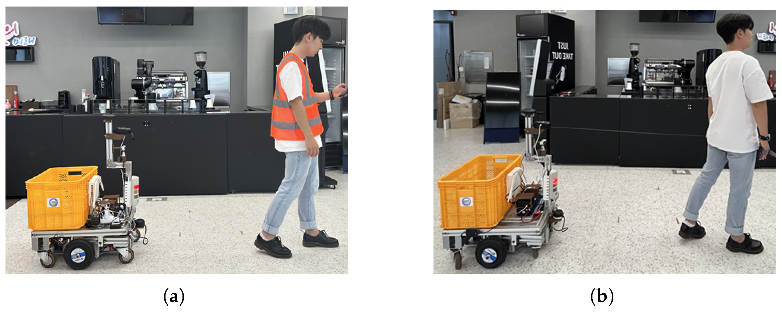
The experiments were conducted in an indoor office environment with movable obstacles, as shown in
Figure 9. Both obstacle-free and obstacle-rich scenarios were considered to evaluate the behavior of HDWA under different planning conditions. The robot was configured to follow only a target wearing an orange vest, allowing the vision module to distinguish the target from other objects in the environment. The tracking margin
was fixed at 1.5 m to maintain a safe following distance between the robot and the target.
The experimental scenarios were designed to verify three operating conditions. First, the robot followed the target without obstacle interference. Second, the robot stopped when no feasible avoidance path was available. Third, the robot generated left-side or right-side avoidance behavior when obstacles blocked the direct path to the target. These scenarios were used to examine whether the proposed HDWA could selectively activate avoidance computation according to the obstacle configuration.
5.3. Candidate-Evaluation Workload Analysis
The candidate-evaluation workload of the proposed HDWA was compared with that of representative path-planning methods, including A* [
9] and conventional DWA [
12]. The comparison focused on the number of candidate evaluations required to generate collision-avoidance behavior in an occupancy grid map with a cell size of 0.1 m. In the test condition, the target was positioned 2 m ahead of the robot.
A* was included as a representative global planning method. Since A* expands nodes over a map-based search space, its search workload depends on the search depth and map size. In contrast, DWA and HDWA are local planning methods that evaluate a limited set of candidate motions or directions. Therefore, the quantitative comparison in this experiment focused on the candidate-evaluation workload of DWA and HDWA.
In conventional DWA, 13 candidate paths were generated at 10° intervals over a range of ±60°. Each candidate was evaluated along the prediction horizon. In the proposed HDWA, the number of evaluated candidates varied according to the obstacle condition. When no obstacle interfered with the direct target-following path, HDWA used only the Movement Dynamic Window State and avoided unnecessary direction-level evaluation. When obstacles were present, HDWA activated the Direction and Detail Dynamic Window States and generated additional candidate paths for avoidance.
All candidate paths were evaluated over the same 20-point prediction horizon. Accordingly, the number of candidate-point evaluations was used as a common measure of the repeated trajectory-evaluation operations.
Table 2 summarizes the minimum and maximum evaluation workloads of the compared planners.
Let H denote the number of evaluation points along each candidate path, and let and denote the numbers of candidates evaluated in the Direction and Detail Dynamic Window States, respectively. The candidate-evaluation complexity of HDWA is when only the Movement Dynamic Window State is activated and when all three states are activated. In comparison, conventional DWA evaluates 13 candidates at every planning cycle and therefore requires candidate-evaluation operations.
Based on
Table 2, HDWA requires 7.7% to 69.2% of the candidate-point evaluation workload of conventional DWA, corresponding to a reduction of 30.8% to 92.3%. Even when the Direction and Detail Dynamic Window States are both activated, the maximum HDWA workload is limited to nine candidate paths, compared with the fixed 13 candidates evaluated by conventional DWA.
5.4. Collision Avoidance Verification Through Target Following
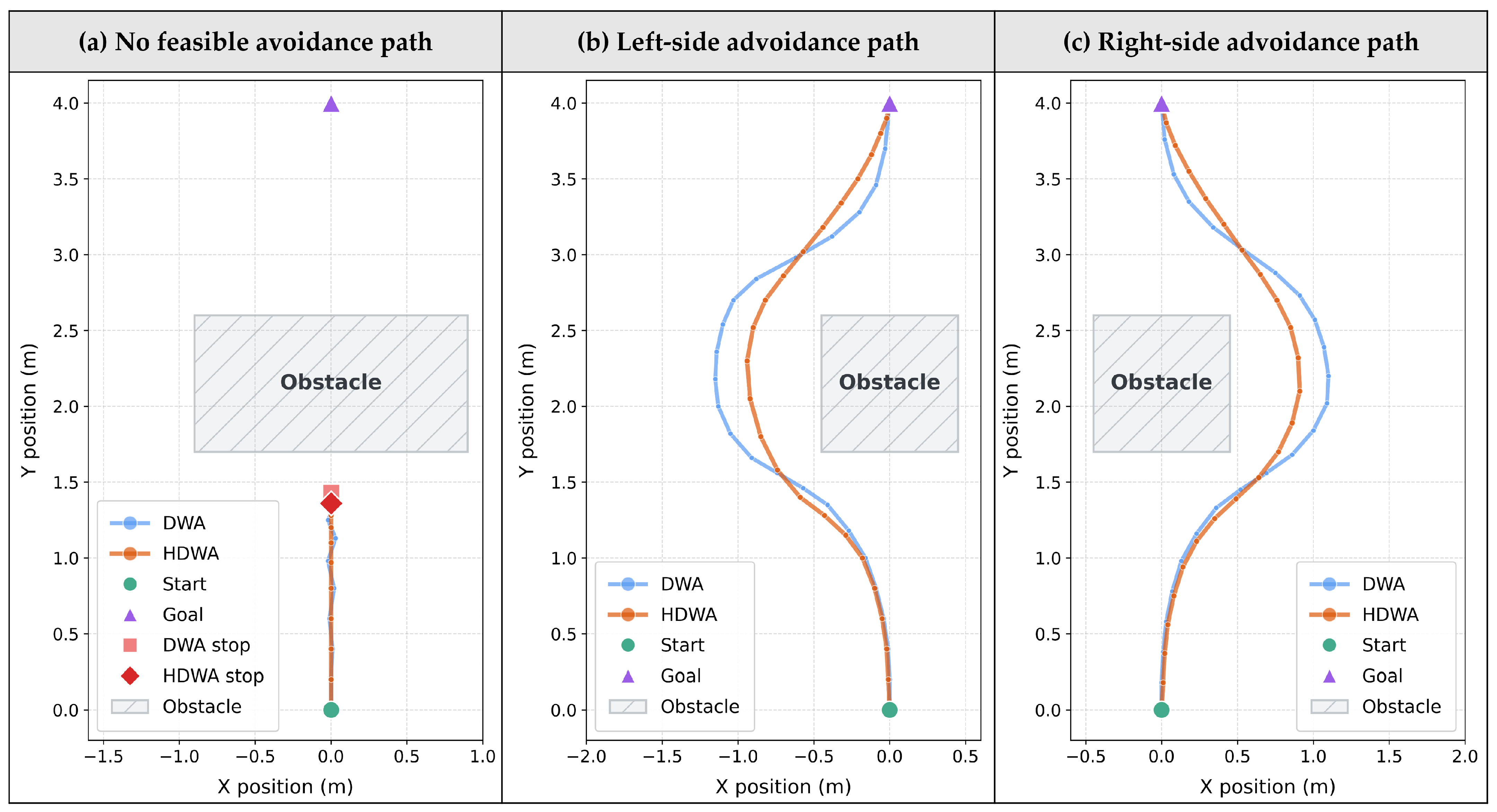
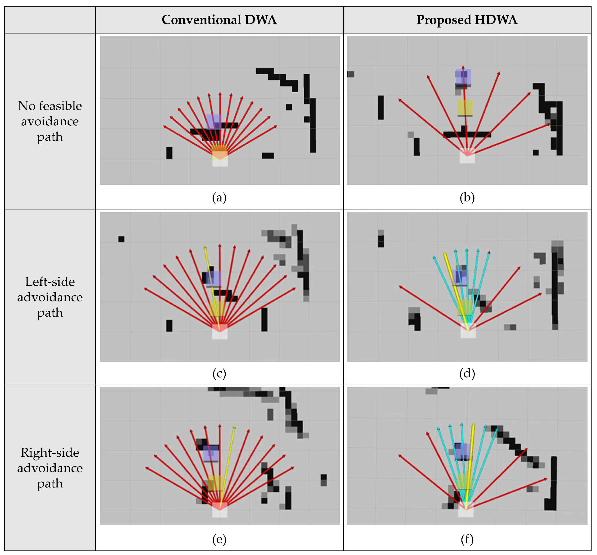
The qualitative collision-avoidance behaviors of conventional DWA and the proposed HDWA are compared in
Figure 10 under three obstacle configurations: no feasible avoidance path, left-side avoidance, and right-side avoidance. Conventional DWA uniformly generates and evaluates the predefined set of candidate trajectories regardless of the obstacle configuration. In contrast, HDWA conditionally activates the Direction and Detail Dynamic Window States according to whether a feasible target-following direction is available.
When no feasible avoidance path is available, the proposed method generates a stop command to prevent collision. When a feasible bypass exists, HDWA first selects a coarse avoidance direction and then refines the candidate trajectories around the selected direction. As shown in the left-side and right-side avoidance cases, HDWA concentrates candidate evaluation on the feasible side of the obstacle while preserving progress toward the target.
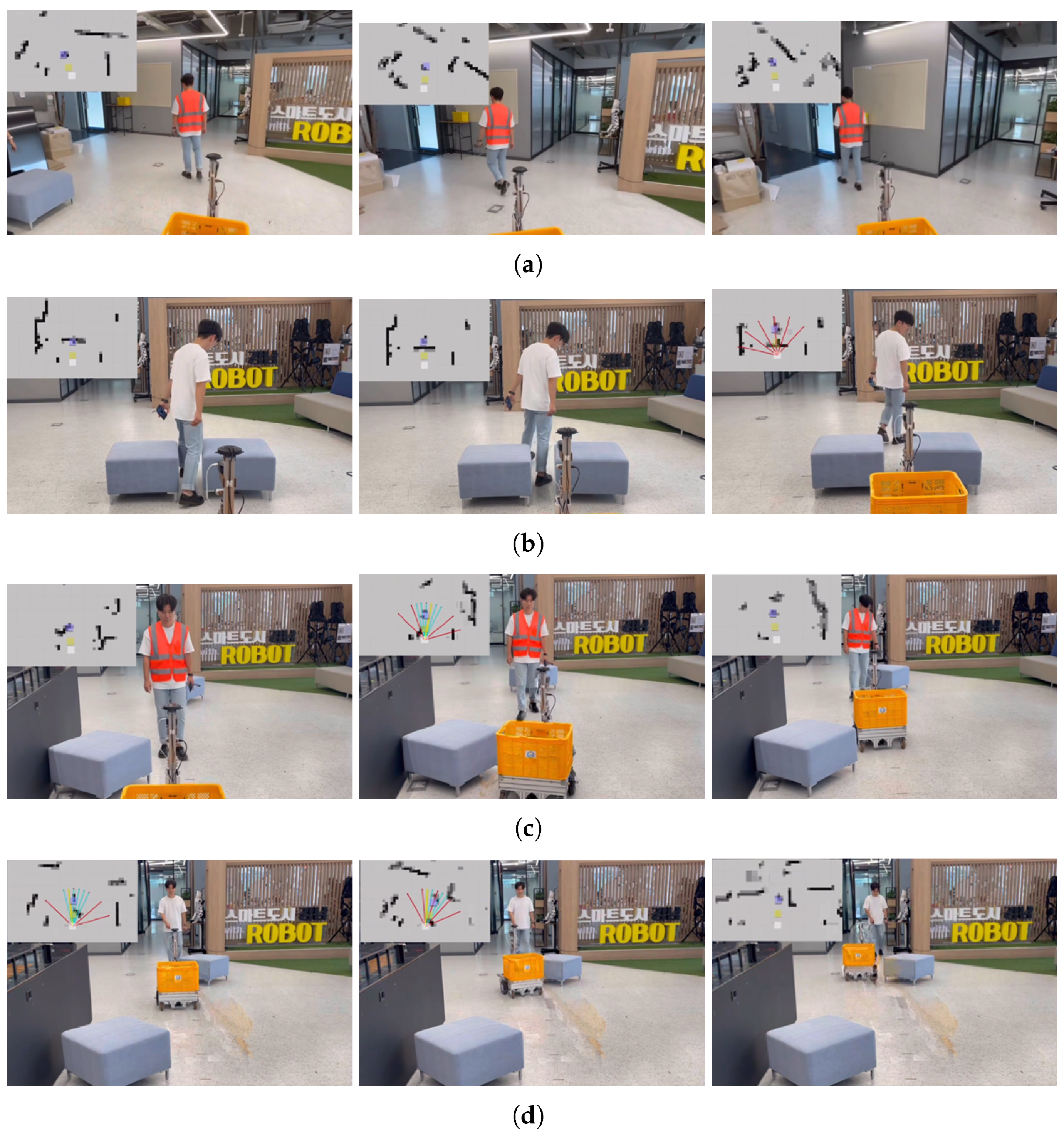
The physical driving results of the proposed HDWA are shown in
Figure 11, complementing the local planning results presented in
Figure 10. The three images in each scenario illustrate the temporal progression of the robot motion from the initial approach to the resulting stopping or avoidance behavior. In the obstacle-free scenario, the robot maintained target-following motion without unnecessary avoidance behavior. When no feasible avoidance path was available, the robot stopped before entering the blocked region. In the left-side and right-side avoidance scenarios, the robot generated an appropriate detour according to the obstacle configuration and continued following the target after passing the obstacle. These results show that the local goals generated by HDWA were translated into physically executable stopping and avoidance motions on the robot platform.
To complement the qualitative results, the recorded robot trajectories of conventional DWA and the proposed HDWA were quantitatively compared under three obstacle configurations: no feasible avoidance path, left-side avoidance, and right-side avoidance. For each obstacle configuration, both methods were evaluated using the same initial position, target position, and obstacle layout. The path length was calculated as the cumulative Euclidean distance between consecutive trajectory points. The elapsed motion time was measured from the recorded timestamps, from the start of robot motion until either stopping or completion of the avoidance maneuver. The average driving speed was calculated by dividing the path length by the measured elapsed motion time.
Figure 12 compares the recorded robot trajectories of conventional DWA and the proposed HDWA. In the scenario where no feasible avoidance path was available, both planners stopped before reaching the obstacle, while HDWA traveled a shorter distance before stopping. In the left-side and right-side avoidance scenarios, both planners generated feasible collision-free detours. The recorded trajectories indicate that HDWA initiated the avoidance maneuver earlier and changed direction more gradually, whereas conventional DWA exhibited a sharper directional change closer to the obstacle. Consequently, HDWA produced trajectories with smaller lateral deviations and shorter path lengths while maintaining higher average driving speeds during obstacle avoidance.
As summarized in
Table 3, HDWA reduced the path length by 6.5–7.8% across the three evaluated scenarios. In the no-feasible-avoidance scenario, both planners maintained the same average driving speed, and HDWA reduced the measured elapsed motion time by 0.190 s. In the left-side and right-side avoidance scenarios, HDWA increased the average driving speed by 22.0% and 30.8%, respectively, while reducing the elapsed motion time by 24.4% and 28.5%, respectively.
These results indicate that the shorter motion times in the avoidance scenarios resulted from both shorter trajectories and higher maintained driving speeds. Although the same controller settings were applied to both planners, the realized driving speed varied according to the curvature of the generated trajectory. Trajectories with sharper directional changes required larger angular control commands and greater differential wheel-speed adjustments, thereby reducing the forward speed maintained during turning. As illustrated in
Figure 12, HDWA initiated avoidance earlier and generated more gradual directional changes than conventional DWA, allowing the robot to maintain a higher average driving speed. Consequently, HDWA maintained the required stopping and collision-avoidance behaviors while improving trajectory and motion efficiency.
6. Conclusions
In this paper, a compute-efficient human-following robotic mobility system was presented for real-time target tracking and obstacle avoidance on resource-constrained embedded hardware. The system integrates multimodal target recognition, LiDAR-based obstacle perception, HDWA-based local planning, and low-level motion control into a unified perception–planning–control architecture. The proposed HDWA generates a collision-free local goal through three hierarchical states. The Movement Dynamic Window State first checks whether the desired tracking point is directly reachable. If the path is blocked, the Direction Dynamic Window State selects a coarse avoidance direction, which is then refined by the Detail Dynamic Window State. By activating the Direction and Detail states only when avoidance is required, HDWA reduces unnecessary candidate evaluations while preserving target-following and obstacle-avoidance performance.
Experimental evaluations using a low-cost micro-mobility robot platform demonstrated that HDWA reduced the candidate-evaluation workload by 30.8–92.3% compared with conventional DWA. The trajectory analysis further showed a 6.5–7.8% reduction in path length. In the left-side and right-side avoidance scenarios, HDWA increased the average driving speed by 22.0% and 30.8%, respectively, and reduced the elapsed motion time by 24.4% and 28.5%, respectively. These results indicate that HDWA improves trajectory and motion efficiency while maintaining safe target-following and obstacle-avoidance behavior on a resource-constrained embedded platform.
Future research will focus on repeated-trial statistical validation, direct measurement of end-to-end planning latency and energy consumption, outdoor pedestrian-environment validation, and more diverse service-robot scenarios involving dynamic human and obstacle interactions.
Author Contributions
Conceptualization, J.K. and H.S.; methodology, J.K. and H.S.; software, J.K.; validation, J.K., H.Y. and H.S.; formal analysis, J.K. and H.Y.; investigation, J.K. and H.Y.; resources, H.S.; data curation, J.K.; writing—original draft preparation, J.K.; writing—review and editing, H.Y. and H.S.; visualization, J.K.; supervision, H.S.; project administration, H.S.; funding acquisition, H.S. All authors have read and agreed to the published version of the manuscript.
Funding
This research was funded by the Ministry of Science and ICT (MSIT), Republic of Korea, through the Information Technology Research Center (ITRC) support program, grant number IITP-2026-RS-2024-00437494, administered by the Institute for Information & Communications Technology Planning & Evaluation (IITP); and by the Regional Innovation System & Education (RISE) program through the Seoul RISE Center, grant number 2026-RISE-01-019-04, funded by the Ministry of Education and the Seoul Metropolitan Government. The APC was funded by [APC FUNDER].
Institutional Review Board Statement
Ethical review and approval were not required for this study. This study was an engineering study on a human-following robotic mobility system and did not involve medical, physiological, psychological, or behavioral experiments on human subjects. No personally identifiable information, sensitive personal information, health information, biometric data, survey responses, or interview data were collected, recorded, or analyzed. The Institutional Review Board of Sejong University confirmed that this study did not fall under the category of research requiring ethical approval.
Informed Consent Statement
Informed consent for participation was not required because this study did not involve human-subject experiments and did not collect or analyze personal, sensitive, health-related, biometric, survey, or interview data. Human figures appearing in the experimental scenes were included only to demonstrate the operation of the human-following robotic mobility system. Identifiable human images, if any, were anonymized or used with permission for publication.
Data Availability Statement
The data supporting the findings of this study are available from the corresponding author upon reasonable request. The data are not publicly available because the original experimental images and videos contain human figures and are subject to privacy considerations.
Acknowledgments
This research was supported by the MSIT (Ministry of Science and ICT), Republic of Korea, under the ITRC (Information Technology Research Center) support program (IITP-2026-RS-2024-00437494), supervised by the IITP (Institute for Information & Communications Technology Planning & Evaluation). This work was also supported by the Regional Innovation System & Education (RISE) program through the Seoul RISE Center, funded by the Ministry of Education (MOE) and the Seoul Metropolitan Government (2026-RISE-01-019-04).
Conflicts of Interest
The authors declare no conflicts of interest. The funders had no role in the design of the study; in the collection, analyses, or interpretation of data; in the writing of the manuscript; or in the decision to publish the results.
References
- Booth, S.; Tompkin, J.; Pfister, H.; Waldo, J.; Gajos, K.; Nagpal, R. Piggybacking robots: Human–robot overtrust in university dormitory security. In Proceedings of the ACM/IEEE International Conference on Human–Robot Interaction, Vienna, Austria, 6–9 March 2017; pp. 426–434. [Google Scholar]
- Mahdavian, M.; Nikdel, P.; TaherAhmadi, M.; Chen, M. STPOTR: Simultaneous human trajectory and pose prediction using a non-autoregressive transformer for robot following ahead. In Proceedings of the IEEE International Conference on Robotics and Automation (ICRA), London, UK, 29 May–2 June 2023; pp. 9959–9965. [Google Scholar]
- Leigh, A.; Pineau, J.; Olmedo, N.; Zhang, H. Person tracking and following with 2D laser scanners. In Proceedings of the IEEE International Conference on Robotics and Automation (ICRA), Seattle, WA, USA, 26–30 May 2015; pp. 726–733. [Google Scholar]
- Kwak, J.; Yang, K.; Lee, J.; Koo, J.; Seo, K. Development of autonomous mobile robot control system for changeable target-of-interest object tracking using specific vest. J. Inst. Control Robot. Syst. 2023, 29, 452–457. [Google Scholar] [CrossRef] [Scilit]
- Kawarazaki, N.; Kuwae, L.T.; Yoshidome, T. Development of human-following mobile robot system using laser range scanner. Procedia Comput. Sci. 2015, 76, 455–460. [Google Scholar] [CrossRef] [Scilit]
- Alphard Golf. TFS (Tether Follow Sensor). Available online: https://alphardgolf.com/products/tfs (accessed on 26 May 2026).
- Feng, T.; Yu, Y.; Wu, L.; Bai, Y.; Xiao, Z.; Lu, Z. A human-tracking robot using ultra-wideband technology. IEEE Access 2018, 6, 42541–42550. [Google Scholar] [CrossRef] [Scilit]
- Dijkstra, E.W. A note on two problems in connexion with graphs. Numer. Math. 1959, 1, 269–271. [Google Scholar] [CrossRef] [Scilit]
- Hart, P.E.; Nilsson, N.J.; Raphael, B. A formal basis for the heuristic determination of minimum cost paths. IEEE Trans. Syst. Sci. Cybern. 1968, 4, 100–107. [Google Scholar] [CrossRef] [Scilit]
- Stentz, A. Optimal and efficient path planning for partially known environments. In Proceedings of the IEEE International Conference on Robotics and Automation (ICRA), San Diego, CA, USA, 8–13 May 1994; pp. 3310–3317. [Google Scholar]
- Ferguson, D.; Likhachev, M.; Stentz, A. A guide to heuristic-based path planning. In Proceedings of the International Workshop on Planning Under Uncertainty for Autonomous Systems, International Conference on Automated Planning and Scheduling (ICAPS), Monterey, CA, USA, 5–10 June 2005; pp. 9–18. [Google Scholar]
- Fox, D.; Burgard, W.; Thrun, S. The dynamic window approach to collision avoidance. IEEE Robot. Autom. Mag. 1997, 4, 23–33. [Google Scholar] [CrossRef] [Scilit]
- Karur, K.; Sharma, N.; Dharmatti, C.; Siegel, J.E. A survey of path planning algorithms for mobile robots. Vehicles 2021, 3, 448–468. [Google Scholar] [CrossRef] [Scilit]
- Cai, K.; Wang, C.; Cheng, J.; Silva, C.W.D.; Meng, M.Q.-H. Mobile robot path planning in dynamic environments: A survey. Instrumentation 2020, 6, 90–100. [Google Scholar]
- Eirale, A.; Martini, M.; Chiaberge, M. Human following and guidance by autonomous mobile robots: A comprehensive review. IEEE Access 2025, 13, 42214–42253. [Google Scholar] [CrossRef] [Scilit]
- Acosta-Amaya, G.A.; Miranda-Montoya, D.A.; Jimenez-Builes, J.A. Lightweight two-layer control architecture for human-following robot. Sensors 2024, 24, 7796. [Google Scholar] [CrossRef] [Scilit] [PubMed]
- Plozza, D.; Marty, S.; Scherrer, C.; Schwartz, S.; Zihlmann, S.; Magno, M. Autonomous navigation in dynamic human environments with an embedded 2D LiDAR-based person tracker. In Proceedings of the IEEE Sensors Applications Symposium (SAS), Naples, Italy, 23–25 July 2024; pp. 1–6. [Google Scholar]
- Nguyen, D.P.; Nguyen, T.L.; Tu, M.D.; Quach, C.H.; Truong, X.T.; Phung, M.D. Socially aware motion planning for service robots using LiDAR and RGB-D camera. In Proceedings of the 7th International Conference on Control, Robotics and Informatics (ICCRI), Danang, Vietnam, 26–28 July 2024; pp. 109–114. [Google Scholar]
- Hess, W.; Kohler, D.; Rapp, H.; Andor, D. Real-time loop closure in 2D LiDAR SLAM. In Proceedings of the IEEE International Conference on Robotics and Automation (ICRA), Stockholm, Sweden, 16–21 May 2016; pp. 1271–1278. [Google Scholar]
- Dwijotomo, A.; Rahman, M.A.A.; Ariff, M.H.M.; Zamzuri, H.; Azree, W.M.H.W. Cartographer SLAM method for optimization with an adaptive multi-distance scan scheduler. Appl. Sci. 2020, 10, 347. [Google Scholar] [CrossRef] [Scilit]
- Dobrevski, M.; Skocaj, D. Adaptive dynamic window approach for local navigation. In Proceedings of the IEEE/RSJ International Conference on Intelligent Robots and Systems (IROS), Las Vegas, NV, USA, 24 October 2020–24 January 2021; pp. 6930–6936. [Google Scholar]
- Sun, Y.; Zhao, X.; Wu, J.; Yu, Y. Robot path planning by using improved A* algorithm and dynamic window method. In Proceedings of the 2nd International Conference on Electrical Engineering and Mechatronics Technology (ICEEMT), Virtual, 1–3 July 2022; pp. 413–417. [Google Scholar]
- Zhu, Z.; Xie, J.; Wang, Z. Global dynamic path planning based on fusion of A* algorithm and dynamic window approach. In Proceedings of the Chinese Automation Congress (CAC), Hangzhou, China, 22–24 November 2019; pp. 5572–5576. [Google Scholar]
- Qin, H.; Shao, S.; Wang, T.; Li, Y.; Wang, N.; Yao, C. An improved dynamic window approach for mobile robot dynamic path planning. In Proceedings of the 12th International Conference on CYBER Technology in Automation, Control, and Intelligent Systems (CYBER), Baishan, China, 27–31 July 2022; pp. 348–353. [Google Scholar]
- Xu, Z.; Wei, Y. Mobile robot path planning based on fusion of improved A* algorithm and adaptive DWA algorithm. J. Phys. Conf. Ser. 2022, 2330, 012003. [Google Scholar] [CrossRef] [Scilit]
- Jiang, Z.; Wang, W.; Sun, W.; Da, L. Path planning method for mobile robot based on a hybrid algorithm. J. Intell. Robot. Syst. 2023, 109, 47. [Google Scholar] [CrossRef] [Scilit]
- Ryu, H. Hierarchical path-planning for mobile robots using a skeletonization-informed rapidly exploring random tree*. Appl. Sci. 2020, 10, 7846. [Google Scholar] [CrossRef] [Scilit]
Figure 1.
Overall system architecture of the human-following micro-mobility robot.
Figure 1.
Overall system architecture of the human-following micro-mobility robot.
Figure 2.
Target recognition using camera-based perception or TFS-based relative position sensing.
Figure 2.
Target recognition using camera-based perception or TFS-based relative position sensing.
Figure 3.
LiDAR-based obstacle perception using a two-dimensional occupancy grid map.
Figure 3.
LiDAR-based obstacle perception using a two-dimensional occupancy grid map.
Figure 4.
HDWA-based local path planning for target following and obstacle avoidance. The gray arrows represent candidate local-goal directions, the yellow marker denotes the original desired tracking point , and the red arrow and marker indicate the selected collision-free adjusted local goal .
Figure 4.
HDWA-based local path planning for target following and obstacle avoidance. The gray arrows represent candidate local-goal directions, the yellow marker denotes the original desired tracking point , and the red arrow and marker indicate the selected collision-free adjusted local goal .
Figure 5.
Pure Pursuit-based lateral control for the human-following mobile robot.
Figure 5.
Pure Pursuit-based lateral control for the human-following mobile robot.
Figure 6.
PID-based longitudinal control for maintaining the target-following distance.
Figure 6.
PID-based longitudinal control for maintaining the target-following distance.
Figure 7.
Overall process of the Hierarchical Dynamic Window Approach with Movement, Direction, and Detail Dynamic Window States. The red arrows represent the coarse candidate directions evaluated in the Direction Dynamic Window State, whereas the black arrows represent the refined candidate directions evaluated in the Detail Dynamic Window State. The red circles denote the target or selected local-goal position.
Figure 7.
Overall process of the Hierarchical Dynamic Window Approach with Movement, Direction, and Detail Dynamic Window States. The red arrows represent the coarse candidate directions evaluated in the Direction Dynamic Window State, whereas the black arrows represent the refined candidate directions evaluated in the Detail Dynamic Window State. The red circles denote the target or selected local-goal position.
Figure 8.
Micro-mobility robot platform used for human-following experiments.
Figure 8.
Micro-mobility robot platform used for human-following experiments.
Figure 9.
Examples of target-following operation using different tracking sensors. (a) Camera-based target tracking, (b) TFS-based target tracking.
Figure 9.
Examples of target-following operation using different tracking sensors. (a) Camera-based target tracking, (b) TFS-based target tracking.
Figure 10.
Comparison of collision-avoidance behavior between conventional DWA (left column) and the proposed HDWA (right column) under different obstacle configurations: (a,b) no feasible avoidance path; (c,d) left-side avoidance path; and (e,f) right-side avoidance path. The colored arrows indicate the robot’s direction of motion; their colors are used only for visual distinction.
Figure 10.
Comparison of collision-avoidance behavior between conventional DWA (left column) and the proposed HDWA (right column) under different obstacle configurations: (a,b) no feasible avoidance path; (c,d) left-side avoidance path; and (e,f) right-side avoidance path. The colored arrows indicate the robot’s direction of motion; their colors are used only for visual distinction.
Figure 11.
Driving results of the proposed HDWA-based human-following robot under different obstacle conditions. (a) Case without obstacles, (b) case with no feasible avoidance path, (c) case of collision avoidance to the right, and (d) case of collision avoidance to the left.
Figure 11.
Driving results of the proposed HDWA-based human-following robot under different obstacle conditions. (a) Case without obstacles, (b) case with no feasible avoidance path, (c) case of collision avoidance to the right, and (d) case of collision avoidance to the left.
Figure 12.
Comparison of recorded robot trajectories obtained using conventional DWA and the proposed HDWA under three obstacle configurations.
Figure 12.
Comparison of recorded robot trajectories obtained using conventional DWA and the proposed HDWA under three obstacle configurations.
Table 1.
Nomenclature of PID Control.
Table 1.
Nomenclature of PID Control.
| Variable | Description |
|---|
| Current distance between the robot and the target |
| Distance error between the current distance and the desired following distance |
| Linear velocity command |
| Desired following distance |
Table 2.
Comparison of Candidate Evaluation Load Among Path Planning Methods.
Table 2.
Comparison of Candidate Evaluation Load Among Path Planning Methods.
| Algorithm | Evaluation Principle | Minimum Load | Maximum Load |
|---|
| A* | Graph search over map nodes | Scenario-dependent | Scenario-dependent |
| DWA | Uniform candidate evaluation | | |
| Proposed HDWA | Hierarchical candidate evaluation | | |
Table 3.
Quantitative comparison of trajectory metrics for conventional DWA and the proposed HDWA.
Table 3.
Quantitative comparison of trajectory metrics for conventional DWA and the proposed HDWA.
| Metric | No Feasible Avoidance Path | Left-Side Avoidance Path | Right-Side Avoidance Path |
|---|
| DWA | HDWA | DWA | HDWA | DWA | HDWA |
|---|
| Path length (m) | 1.474 | 1.360 | 4.949 | 4.565 | 4.835 | 4.520 |
| Avg. driving speed (m/s) | 0.60 | 0.60 | 0.41 | 0.50 | 0.39 | 0.51 |
| Traversal time (s) | 2.457 | 2.267 | 12.072 | 9.129 | 12.397 | 8.864 |
| Disclaimer/Publisher’s Note: The statements, opinions and data contained in all publications are solely those of the individual author(s) and contributor(s) and not of MDPI and/or the editor(s). MDPI and/or the editor(s) disclaim responsibility for any injury to people or property resulting from any ideas, methods, instructions or products referred to in the content. |