Abstract
Interoperability between digital models in the manufacturing and AEC domains is a critical issue in the building design of complex systems. Despite the adoption of well-established standards such as STEP (STandard for the Exchange of Product data, ISO 10303-21) for the industrial domain and IFC (Industry Foundation Classes, ISO 16739-1) for the construction domain, communication between these domains is still limited due to differences in conceptual models, levels of detail, and application purposes. Existing solutions for conversion between these formats are few, often proprietary, and not always suitable to ensure full semantic integration in BIM (Building Information Modeling) flows. This study proposes a methodological framework for structured conversion from STEP to IFC-SPF (STEP Physical File), based on information and geometric simplification and data enrichment. The process includes the elimination of irrelevant components, simplification of geometries, merging assemblies, and integration of data useful to the building context. The experimental implementation, carried out using the Bonsai extension for Blender, demonstrates a substantial reduction in geometric complexity and computational load, while maintaining data consistency required for integration into BIM processes. This approach emerges as a scalable, affordable, and sustainable solution for interoperability between industrial and civil models, even in professional environments lacking advanced software development skills.
1. Introduction
Interoperability between digital models is one of the most critical challenges in both AEC (Architecture, Engineering and Construction) and industrial worlds. In their respective fields of application, manufacturing and construction sectors adopt well-established standards for the representation of three-dimensional and information models: the STandard for the Exchange of Product data (STEP) format (ISO 10303-21 [1]) for manufacturing and the Industry Foundation Classes (IFC) format (ISO 16739-1 [2]) for construction. However, although both standards are based on explicit and formally defined data structures, communication between these two worlds remains complex due to substantial differences in conceptual models, levels of detail, and application purposes. This study proposes a methodological framework aimed at addressing the need for integration between these distinct disciplinary domains. Following a comparative analysis of the conceptual and structural differences between the standards, this research develops strategies that go beyond simple geometric data conversion. Instead, it focuses on aligning the differing paradigms of modeling, design logic, and product interpretation that characterize the manufacturing and construction sectors.
The manufacturing industry during the design phase makes extensive use of Computer-Aided Design (CAD) modelers, often based on proprietary software. The growing need to exchange design data has critically highlighted the problem of interoperability between different systems. In manufacturing, CAD models can be classified into two main categories [3]:
- Low-level CAD models: These are exclusively viewable representations characterized by the presence of faceted geometries or “frozen” solids devoid of product-related management information. Typical formats include STereo Lithography interface format (STL) and Initial Graphics Exchange Specification (IGES).
- High-level CAD models: These include not only geometric information, represented in various forms (pixels/voxels, faceted triangles, exact surfaces, exact solids) but also geometric tolerance data, Product Manufacturing Information (PMI), and product-specific properties. PMI includes, among others, geometric dimensioning and tolerances, surface texture, finishing requirements, process annotations, material specifications, and welding symbols [4].
The use of high-level CAD models is crucial to the Model-Based 3D Engineering approach of fully conveying design information through the three-dimensional model, with the goal of ensuring long-term data maintenance. In this context, the international standard ISO 10303 is a key tool to enable interoperability between different CAD systems, via the neutral data structure STEP [5]. Within this standard, several Application Protocols (APs) have been defined to meet the specific needs of various industries. The main ones include the following [6]:
- AP203—Configuration Controlled Design: designed for the aerospace industry, defines geometries, topologies, and configuration management mechanisms for parts and assemblies;
- AP214—Core Data for Automotive Mechanical Design Processes: developed for the automotive industry, extends the functionality of AP203 by including support for color and geometric tolerances;
- AP242—Managed Model-Based 3D Engineering: integrates the contents of the previous protocols, providing a unified format for managing 3D model-based engineering. STEP AP242 enables efficient collaboration between design and manufacturing by facilitating the automated exchange of design specifications between different systems and organizations [7].
In addition to STEP formats, there are additional open formats. The Jupiter Tessellation (JT) format, initially developed by Siemens and later adopted as an ISO 14306 standard [8] in 2012 [9], is known for its effectiveness in geometric visualization and support for PMI, making it suitable for use in Model-Based Engineering contexts. However, despite its openness, the adoption of JT outside the Siemens ecosystem remains limited. Another emerging format is QIF (Quality Information Framework), standardized under ISO 23952 [10]. QIF defines an integrated set of information models that facilitate the exchange of data across the entire quality cycle in manufacturing, from product design to inspection planning and execution to analysis and reporting [11]. Although QIF represents a very promising solution, its adoption is still in the early stages, and, at present, its deployment remains limited. STEP thus emerges as a more widely used format in the manufacturing landscape.
The construction industry has also been confronted with interoperability issues in the exchange of digital data, particularly in the BIM context. Beginning in 1994, with the development of IFC, the path toward defining an open data model standard capable of meeting the interoperability requirements specific to the BIM context was formally initiated [12]. Currently, IFC represents the most widely adopted open standard in the industry and corresponds to ISO 16739-1 [2]. Among the proposed formats, the most used one is IFC STEP Physical File (IFC-SPF) [13], which, similarly to the STEP format, is formally described through the EXPRESS language, in accordance with the ISO 10303-21 standard [1].
The integration between the manufacturing and construction sectors is particularly critical in complex construction projects, where industrially produced mechanical components—such as building services equipment, machinery, and prefabricated systems—must be accurately incorporated into the Building Information Model (BIM). The need for the integration of different file formats describing construction or manufactured products through open standards has already been recognized in prior studies [14,15,16,17]. However, robust open-source solutions to support such integration remain scarce. In the absence of standardized and accessible tools for efficient conversion of STEP models to the IFC-SPF (STEP Physical File) format, the transposition of information is often carried out through manual re-modeling of components. This process is not only time-consuming but also highly prone to errors. Currently available integration solutions, in most cases, are limited to importing geometries in the form of meshes into the BIM as external coordination files and thus lack semantic structure. Even in cases where meshes are incorporated within the IFC file, they are generally associated with generic entities such as IfcBuildingElementProxy, resulting in the loss of key semantic information. In addition, the geometric complexity of the generated meshes results in a significant increase in computational load and a reduction in the efficiency of authoring software. The result, therefore, is the suboptimal management of industrial components, resulting in an uncontrolled process that causes loss of relevant information and transfer of overly detailed content relative to actual civil design needs. This situation has led many companies to adopt proprietary solutions that enable the integration of multiple domains within the same proprietary ecosystem [14,17]. An additional challenge arises from the fact that, although the data models involved are based on the same underlying EXPRESS schema language, they often define classes, properties, and relationships in fundamentally different ways. This inconsistency necessitates the development of advanced strategies for effective information exchange. Furthermore, the integration of manufacturing and construction domains is complicated by their inherently different objectives and modeling paradigms. Industrial models, designed for manufacturing processes, typically exhibit a high level of geometric and informational detail that exceeds the needs of the AEC sector and may significantly compromise the performance of BIM authoring environments. Therefore, it is essential to apply filtering and simplification procedures to ensure that only relevant information is retained in accordance with the functional requirements of civil design. In the absence of a structured approach to data transformation, there is a high risk of transferring redundant or irrelevant content, which can negatively affect the readability, maintainability, and overall interoperability of the resulting digital models.
The importance of the contribution lies in the possibility of bridging the existing gap between manufacturing and civil design by proposing a consistent, lightweight, and interoperable information flow between the two domains. This paper proposes a methodological framework for the structured transformation of STEP models to the IFC-SPF format, with a specific focus on semantic and geometric optimization of the model to ensure its full usability in building and civil design contexts. It also presents an operational implementation of the methodological framework based on real-world design requirements. This implementation is distinguished using open-source tools, selected based on principles of scientific repeatability and transparency. It also adopts a simple and accessible user interface designed to facilitate application in professional settings even by practitioners without programming skills. Experimental results show a significant reduction in the computational load and size of the IFC files produced, with low processing time and information quality adequate for the purposes of BIM design.
2. Materials and Methods
2.1. Literature Review
Literature reviews constitute a fundamental tool for synthesizing the current state of knowledge on a given topic and identifying promising directions for future research [18]. In this study, the review was conducted using a systematic, rigorous, and transparent approach, with detailed documentation of the methodological criteria employed. This was done to ensure the replicability of the process by other researchers and to enhance the robustness and reliability of the results obtained.
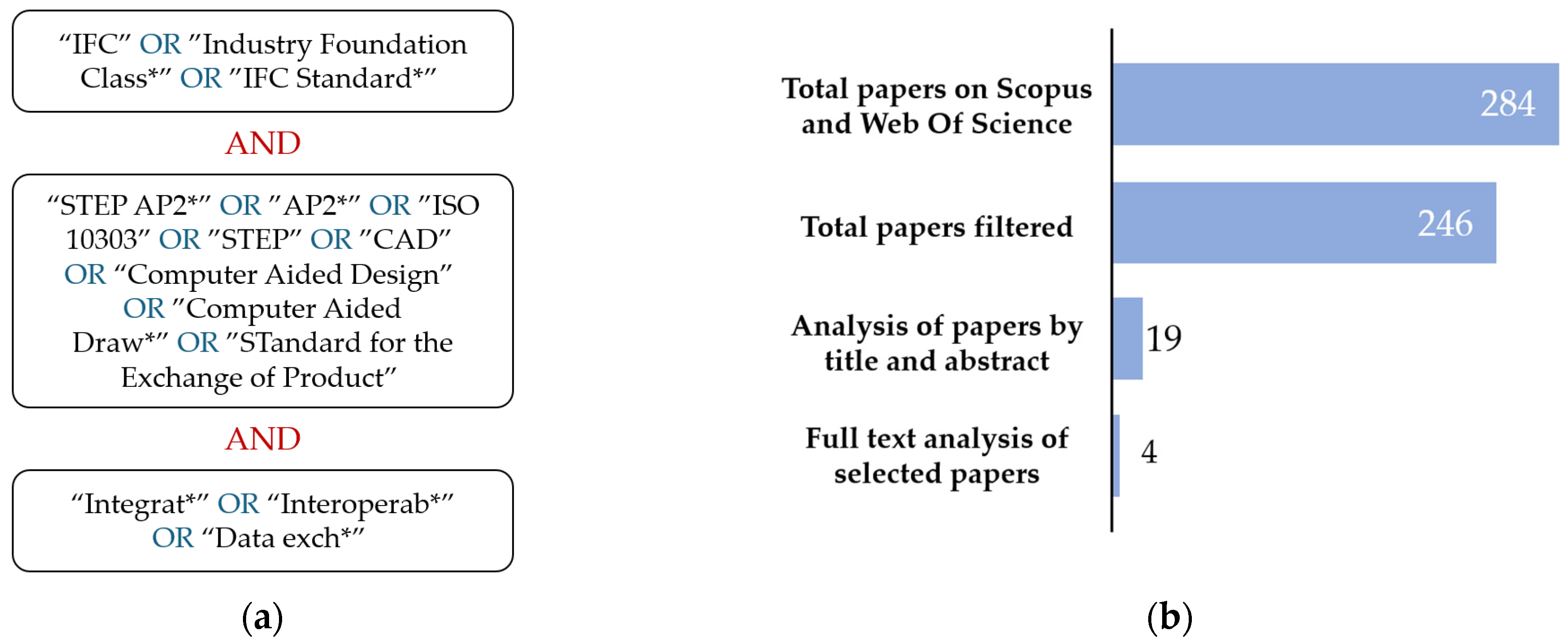
A bibliographic search was carried out using the Scopus and Web of Science databases, selected for their broad multidisciplinary coverage. The search was limited to the fields “Title”, “Abstract”, and “Keywords”. The keywords used are presented in Figure 1a, while Figure 1b graphically illustrates the number of articles identified and selected at each stage of the review process. Results were filtered by language (English) and disciplinary area, including only contributions in the fields of “Engineering”, “Computer Science”, and “Business, Management and Accounting”. In the initial screening phase, titles and abstracts were reviewed to exclude articles unrelated to the topic of CAD–IFC integration. Subsequently, the full texts of the selected articles were examined in depth, with the aim of including only studies that explicitly addressed the integration between CAD and IFC. Articles of a highly generic nature were excluded in favor of those presenting concrete integration methodologies or addressing the integration of relevant standards.
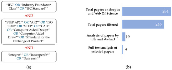
Figure 1.
Literature review: (a) selected keywords; (b) numbers of papers for each review stage.
Although limited in scope, the existing literature provides some relevant insights into the strategies employed to address the complexity of CAD–IFC integration. In [15], a toolkit is presented for the semantic enrichment of CAD models through the integration of IFC data. The prototype adopts a multi-tier architecture with a graphical user interface embedded in commercial software and remote access via web servlets. While the system supports the editing and storage of semantic metadata, the approach entails significant infrastructural demands and is difficult to replicate without specialized IT expertise. Furthermore, the system relies on proprietary tools and does not perform actual format integration or conversion, restricting its functionality to the semantic enhancement of CAD objects. Similarly, ref. [14] introduces a multi-tier platform aimed at integrating standards such as STEP and IFC to address fragmentation in the sector. Although the platform facilitates unified data visualization, it does not enable the conversion of data models within infrastructure-oriented software, thereby limiting design phase interoperability. Once again, architectural complexity hinders widespread adoption by industry professionals.
Reference [16] approaches the interoperability challenge from a formal perspective, applying set theory to propose the use of data model subsets to reduce complexity and support targeted applications. Although no explicit mapping or conversion mechanism is provided, the methodology constitutes a valuable foundation for the development of semantic interoperability strategies.
In [17], the state of international standards is critically examined, highlighting difficulties in heterogeneous information exchange. These challenges are attributed to the lack of a neutral data format and to the strategic choices of software vendors, who tend to favor proprietary ecosystems over the adoption of open standards—often subject to slow and complex revisions. The study emphasizes the urgent need for new strategies that enable effective interoperability across data formats.
Overall, the analysis reveals a scarcity of relevant contributions, largely confined to the 2006–2008 period. This highlights a clear gap in the literature, exacerbated by the lack of consideration for recent standard versions such as STEP AP242 and IFC4.3_ADD2. The absence of up-to-date and operational solutions underscores the pressing need for research focused on the development of lightweight, interoperable tools that are independent of proprietary ecosystems and complex infrastructures, with the potential to address the persistent fragmentation in the AEC sector.
2.2. Methodological Framework
In complex building projects involving a strong mechanical component or the integration of manufacturing products, a dialogue between industrial CAD models and BIMs is necessary. Indeed, it is essential for civil designers to be able to visualize, query, and integrate mechanical components within their working environments to properly plan structural elements, plant systems, supporting works, and so on. The not-achieved acceptance in the AEC industry of the STEP data model represents a significant barrier to interoperability [19]. A key contributor to this issue is the presence of inconsistent and incompatible schemas across applications and standards, with divergent definitions of entity types impeding seamless data exchange [17]. This limitation affects a broad range of CAD models [20] and has direct consequences for commercially available software, which often restricts export capabilities to either the STEP or IFC format based on their domain-specific requirements [21]. Furthermore, it is noted that software capable of performing STEP to IFC-SPF conversion is often tied to proprietary ecosystems and, in most cases, is available only through paid plug-ins. It should be emphasized that by “integration” we do not mean a mere transposition of data between one format and another; in fact, the differences between the conceptual models and modeling logics of the two sectors (manufacturing and AEC) are substantial. In the manufacturing context, modeling is characterized by a high level of detail, including explicit representation of each individual product component (e.g., screws, bolts, flanges, plates, etc.) that is functional for industrial production, but excessive for the construction sector. Such detail introduces a significant computational load, in terms of both geometric and informational complexity. In addition, much of the information conveyed by STEP models, such as geometric tolerances, surface specifications, welding symbols, process notes, or material characteristics, is irrelevant to civil design. Therefore, to ensure effective integration between CAD and BIMs, it is necessary to selectively filter the information to be transferred, considering the actual needs of design and AEC management. Such selection is essential to avoid the propagation of superfluous data that, in addition to reducing the computational efficiency of the software involved, could compromise the readability, maintainability, and overall quality of the information model.
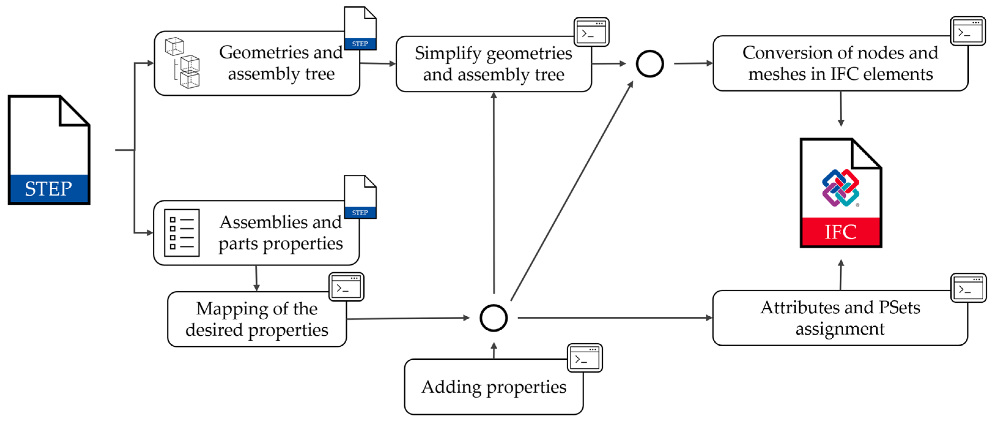
The proposed framework is not limited to simply converting a STEP file to IFC-SPF format but defines a structured procedure for controlling and managing geometric and semantic information, with the goal of generating consistent and fully usable output within civil engineering design software. The workflow is shown in Figure 2.
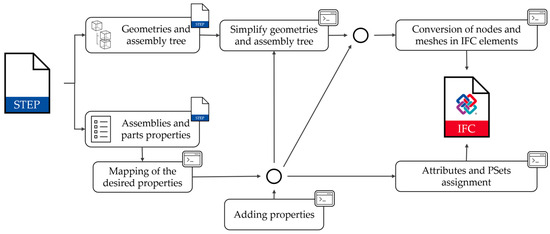
Figure 2.
Methodological framework to convert a STEP file to IFC.
From the AEC perspective, the essential information to be extracted from the STEP file concerns geometries, the assembly tree, and the properties associated with parts and assemblies. The properties of parts and assemblies must be properly mapped and transformed into attributes compatible with the IFC data model to ensure an effective semantic transition. In addition, the framework provides the ability to enrich the model with additional properties not originally present in the STEP file. Such additional information can come from external sources such as databases, CSV files or other software. It is necessary to integrate external data because it is difficult for the manufactory domain to produce models with the specific needs of civil design. Integrable properties and information include instructions for geometric simplification and assembly tree simplification. By analyzing the assembly tree, it is possible to identify and exclude elements that are not relevant to the design (e.g., screws, flanges, labels, cables, etc.), thus reducing the overall number of entities to be managed. The framework provides for the merging of assemblies into unitary entities, reducing the number of managed objects, improving efficiency in model management and significantly reducing computational load and file weight. Regarding geometries, an automatic simplification procedure is implemented for overly detailed shapes to make the model lighter and more usable in civil design software, without compromising the information essential for integration into the AEC context. Finally, the nodes of the assembly tree and the resulting geometries (usually in the form of meshes) are converted into IFC entities, with which the previously processed attributes and properties are associated.
The result is an optimized IFC file, which represents a simplified and semantically coherent version of the original product, specifically tailored to the requirements of design in the AEC sector.
2.2.1. Product Data Management (PDM)
The collection, organization, and management of product information are commonly referred to as Product Data Management (PDM). Within the STEP context, PDM is supported by the STEP PDM Schema, a subset of STEP entities designed to represent typical PDM concepts and structures. The entity relationship model that underpins the STEP standard is sufficiently generic and flexible to accurately represent properties of any product type, regardless of the application domain [22]. Furthermore, there are some dictionaries of proprieties like ISO 13584 (PLIB) [23] that establish standardized EXPRESS-based information models for product classification libraries, enabling interoperability and reuse of shared concepts across domains [24].
The aim of this chapter is not to provide an exhaustive analysis of the STEP data structure nor an in-depth discussion of the attribution of properties, but rather to provide some basic operational indications on the insertion of properties within a STEP file to support the implementation of the framework described in this study. The complete definition of the entities included in the STEP schema can be found in [25], while a series of exemplary diagrams of the EXPRESS schema is available in [26]. As software for the visualization and analysis of the properties, PMIs and all the data contained within STEP [27] were used.
In the STEP standard, the concept of product is represented by a generic entity that can describe either a single part or an assembly. The concept of product could be a hierarchical structure where a product’s assemblies and parts occupy subsequent levels [28]. An assembly is a type of product composed of one or more parts or other nested assemblies, and parts are the basic components used to construct assemblies. So, the elementary unit of the STEP model is represented by the part. A property is the definition of a special quality and can reflect physical or arbitrary measures, defined by the user. In the PDM schema, a general model is used for the instantiation of property information. The information reported below is a reworking from [29]. The diagrams reported do not illustrate the entire EXPRESS schema but only a specific subset. The notation adopted is described in Figure 3, which specifies that the directionality of the attributes is indicated by a graphic symbol placed at the end of the relation, thus highlighting the direction of association between the entities involved.
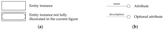
Figure 3.
Notation for representing EXPRESS schemas: (a) entity notation; (b) attribute notation.
To specify the properties associated with product data, the property_definition entity is used. This entity enables the association of a measurement with a specific product_definition. The structure of the relationships between the entities is illustrated in Figure 4, while a detailed description of the entities involved is provided in Table 1.
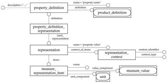
Figure 4.
EXPRESS Schema of property_definition assignment to product_definition.

Table 1.
Entity descriptions and recommendations related to property_definition.
In cases where properties are associated not with a quantitative measurement but rather with a description or a generic textual value, a representation like that shown in Figure 3 is adopted. In this context, however, the measure_representation_item entity is replaced by the descriptive_representation_item class. The latter is characterized by only two attributes, name and description, where the description field represents the value assigned to the property in the form of a textual description.
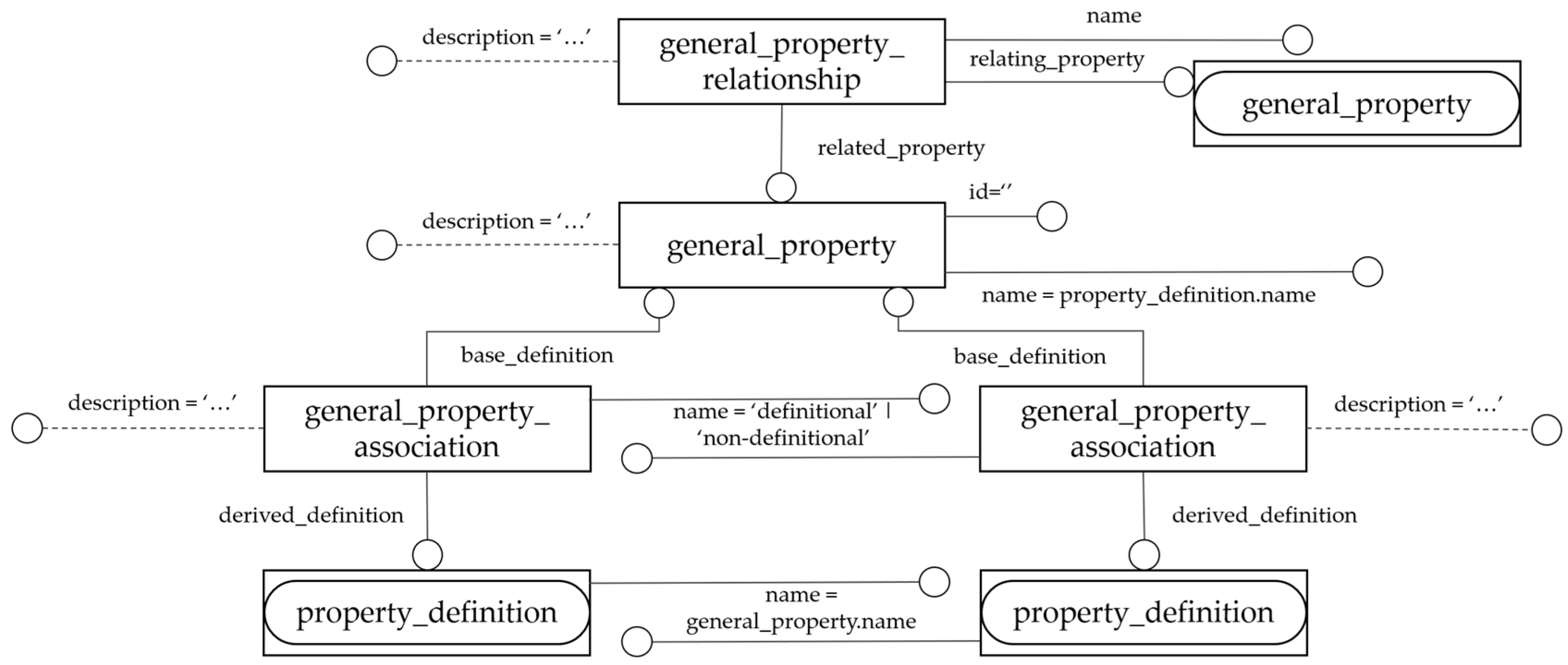
The PDM Schema allows for the identification of properties independently of their actual association with a product. These properties are referred to as general_property, and they link multiple property_definition instances of the same type through the general_property_association entity (i.e., all properties measuring the weight of an object may all be associated with a general_property named “weight”). The general_property_association can be of a definitional type if the property can be used to distinguish one product from another or non-definitional if it does not represent a distinguishing feature. The PDM schema also supports the specification of relationships between two general property objects. These relationships can be used to indicate that the value of one property can be derived from the value of another. This relation is modeled using the general_property_relationship entity. The structure of the relationships and the entities involved is illustrated in Figure 5, while a description of the entities is provided in Table 2.
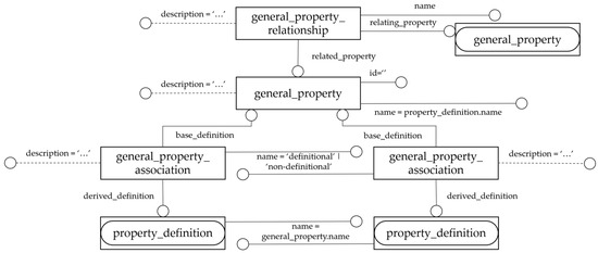
Figure 5.
EXPRESS Schema of general_property.
Table 2.
Entity descriptions and recommendations related to general_property.
2.2.2. Mapping of the Desired Properties
It is necessary to establish a map between all properties associated with objects and the corresponding properties defined in the IFC schema. Manufacturing products often include properties that are not relevant to the context of civil design; therefore, an appropriate mapping process allows for the control of information flow and the selection of only the relevant properties. Generally, many of the data relevant to the AEC domain are not included in the STEP file, as they are not considered pertinent for manufacturing purposes. As a result, it is essential to provide the ability to integrate additional data outside the STEP standard.
Within the STEP file, products are not identified by an ID but by a unique Instance Name within the project. Therefore, this identifier must be used to associate properties coming from external sources.
Within the proposed framework, the information is divided into two main categories:
- Simplification information: includes data required for the proper functioning of the framework, such as indications on whether to retain or remove elements deemed unnecessary, simplification of their geometry, or potential grouping into assemblies to optimize information management.
- Manufacturing and civil product information: includes attributes and properties associated with parts or assemblies, intended to be incorporated as IFC model properties.
2.2.3. Geometries and Assembly Tree Simplification
Within the proposed framework, the process of geometric and informational optimization of STEP models is structured into three distinct phases:
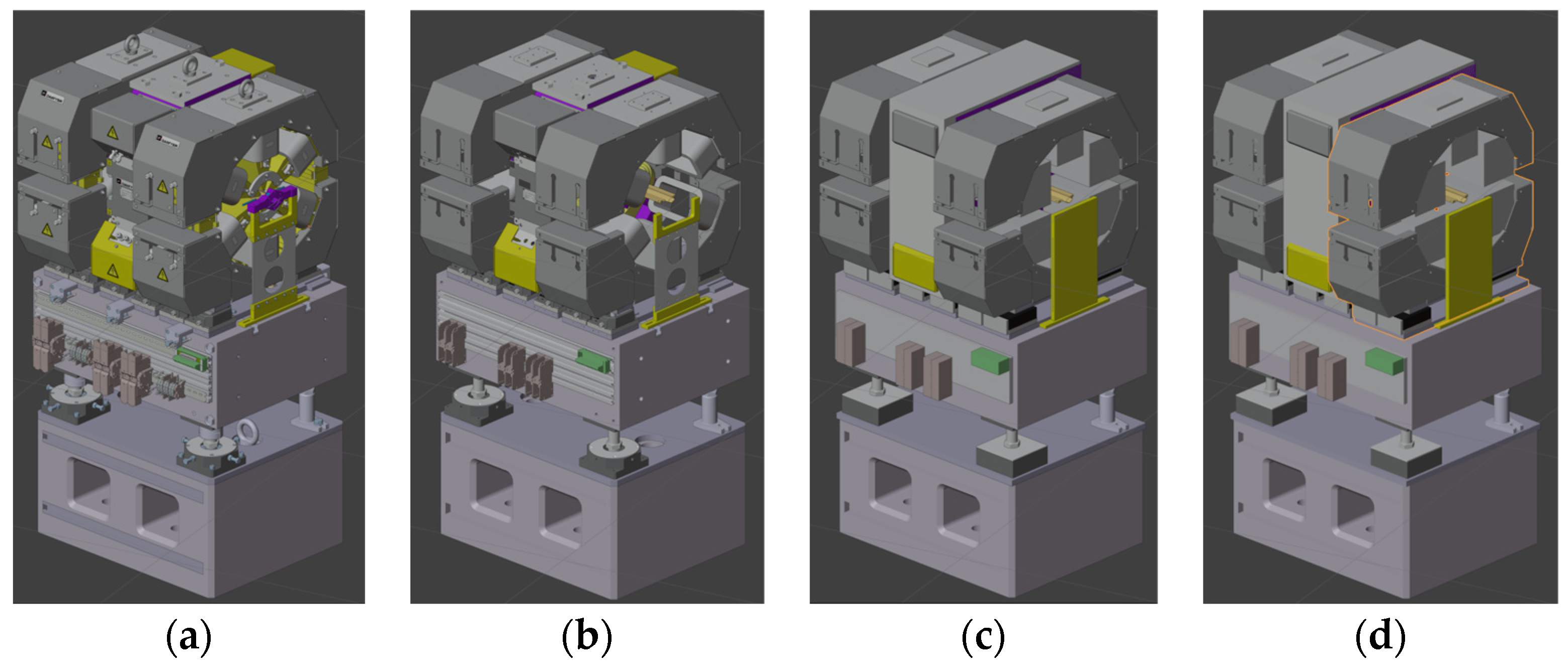
- Elimination of non-relevant elements: The STEP file may contain numerous objects and highly detailed geometric features that are not pertinent to the context of civil design. These include very small components (e.g., screws, bolts, flanges, labels) or internal, non-visible parts (such as coils, rotors, circuits, pistons, etc., typically found inside motors or other devices). As shown in Figure 6b, removing such elements allows for a significant reduction in computational load, thereby improving processing efficiency.
 Figure 6. Geometry and assembly tree simplification: (a) a manufacturing assembly; (b) a manufacturing assembly without non-relevant parts; (c): a manufacturing assembly without non-relevant parts and with some simplified geometries; (d): a manufacturing assembly without non-relevant parts, with some simplified geometries, and with aggregated components into a higher-level assembly.
 - Geometric simplification: As illustrated in Figure 6a, certain geometric entities can be extremely complex, characterized by a high number of vertices, faces, and triangles, which negatively impact performance. However, in many AEC applications, a high level of detail is not required. It is therefore appropriate to generate simplified versions of these objects or minimal representations such as bounding boxes, given that object identification can also rely on the name or associated attributes and properties. However, simplification should be applied selectively. Elements requiring precise geometric representation for functional or visual purposes must be preserved in their detailed form. This includes, for example, MEP connectors, components that facilitate internal system routing, or elements whose shape is crucial for accurate identification or interaction. In contrast, components that approximate simple geometric volumes (i.e., rectangular prisms) and elements where volumetric information suffices for analysis or visualization may be simplified without compromising the integrity of the model. An example of the result of the geometric simplification is shown in Figure 6c.
- Aggregation of components into a higher-level assembly: In the AEC domain, the concept of a “product” takes on a different meaning compared to manufacturing, as it operates on a different design scale. Consequently, the detail of individual components becomes less relevant in favor of identifying the final product. It is therefore necessary to define a maximum decomposition level, beyond which individual parts are merged into a single assembly, simplifying information management and reducing model complexity. As shown in Figure 6d, the selected magnet, highlighted by the orange outline, is treated as a single product, obtained by merging all its constituent components.
2.2.4. Conversion to IFC Elements with Attribute and Property Assignment
The final phase of the process involves converting assemblies and individual parts into IFC entities. Assemblies are mapped to the IfcElementAssembly class, which is specifically designed to represent structures composed of multiple related elements. As illustrated in the example shown in Figure 7, the IfcRelAggregates relationship is used to explicitly model the hierarchical decomposition between the assembly and the entities it contains. For the conversion of individual parts, a specific IFC class must be assigned based on the nature of the product. In Figure 7, this process is represented using the generic abstract class IfcObjectDefinition, from which the specific IFC types are derived. Depending on the selected class, it is possible to associate dedicated attributes, Property Sets (PSets), and custom properties, ensuring a consistent and comprehensive description of the object. This procedure enables the faithful reconstruction of the parent–child relationship in the assembly tree within the IFC model, preserving the original information structure and ensuring full interoperability with BIM environments.
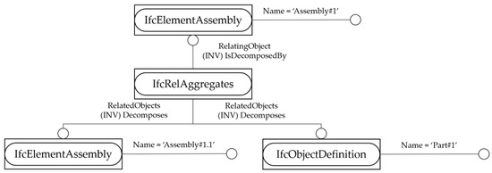
Figure 7.
EXPRESS Schema of the IfcRelAggregates relation between IfcElementAssembly and entities it contains.
The IFC data model includes a range of project-related information that is typically absent from STEP files, which are primarily oriented toward industrial manufacturing. As such, this type of project-level data cannot be directly mapped from STEP, as it pertains to the management and organization of construction projects—a domain-specific aspect of the AEC industry. Since these data elements are generally defined once and remain consistent throughout the project, automating their input is not necessary. Instead, user-friendly interfaces, such as those available in tools like Blender, provide an effective and practical means for manual input.
3. Results
3.1. Case Study: Elettra 2.0 Light-Machine
Elettra Sincrotrone Trieste S.C.p.A. located in Trieste, Italy (IT) is a multidisciplinary research center of excellence, open to the international scientific community and active since 1993. The center specializes in the generation of high-quality synchrotron light and free-electron laser radiation. This research center is actively engaged in the development and operation of two major facilities: Elettra and FERMI. In the Elettra light machine, synchrotron light is generated by accelerating electrons along a circular trajectory using magnetic and electric fields. As the electrons are forced to bend their path, they emit electromagnetic radiation—known as synchrotron light—due to the energy loss caused by centripetal acceleration. This radiation is directed through dedicated beamlines to experimental stations, where it interacts with samples of various types and sizes, ranging from nanoscale biological systems (e.g., viruses, proteins) to macroscopic materials. The light produced at Elettra and FERMI supports a wide range of scientific disciplines, including chemistry, structural biology, solid-state physics, materials science, nanotechnology, medicine, and cultural heritage science.
The Elettra machine is currently undergoing a technological upgrade aimed at enhancing its performance, known as the Elettra 2.0 project. This modernization presents complex challenges, such as the integration of industrial and civil design processes, the key aspect addressed in this work. Within the organization, the Mechanical Group employs advanced CAD tools such as CATIA V5 and SolidWorks (Dassault Systèmes) to develop detailed 3D models of the light machine and its associated components. Surrounding this industrial system, a wide range of civil infrastructure—supporting facilities, service networks, and auxiliary structures—must be designed and implemented by civil engineers. This scenario gives rise to the need for seamless information exchange between the industrial and civil design processes. Notably, civil design activities are not only managed by the internal Infrastructure Group but are also frequently outsourced to external companies and professionals. As a public research institution, the organization is subject to Italian regulations that mandate the use of open standards for data exchange, explicitly prohibiting the reliance on proprietary formats. Consequently, IFC-SPF and STEP have been adopted as the standard formats for multidisciplinary collaboration. In this context, the organization has expressed a strong interest in leveraging open and interoperable solutions to support the integration of industrial and civil domains, with the objective of overcoming the disciplinary and technological challenges previously described.
3.2. Operational Implementation of the Methodological Framework
The implementation of the proposed framework can be carried out through a variety of approaches, employing different software libraries, application tools, and workflows, depending on specific design and operational requirements. This section presents the workflow adopted by authors, specifically tailored to the case study under investigation.
The definition of the methodology was preceded by the identification of some key requirements, which guided the selection of tools and the design of the operational architecture, listed as follows:
- Open-source: Priority was given to the use of open-source formats and tools to ensure reproducibility of the procedure, methodological transparency, and the adoption of open technologies with broad documentation availability. This choice facilitates the advancement of research and promotes the sharing of results without proprietary license constraints or technological barriers.
- User-friendly: One of the primary goals was to develop a workflow accessible to a wide range of professionals, including those without advanced IT skills. To this end, emphasis was placed on selecting tools with intuitive graphical interfaces or those already widely used in professional practices such as spreadsheet formats (e.g., CSV). The aim was to reduce adoption barriers and promote the integration of the framework in real-world operational contexts.
The following sections outline the key features and specific aspects of the workflow associated with the operational implementation of the proposed framework.
3.2.1. Tools Selection Criteria
The workflow developed for the implementation of the framework is based on the use of Blender [30], one of the most widely adopted, free, open-source software platforms for three-dimensional geometric modeling [31], integrated with the Bonsai extension [32] (formerly BlenderBIM), specifically designed for managing models in the IFC format. The current version of Bonsai supports the creation of files compliant with the IFC4 schema, which has been adopted in the present study. Future updates of the software are anticipated to enable the generation of IFC models to conform to the latest official release, IFC4.3_ADD2. The choice of Blender was driven by several strategic factors—its broad adoption within the technical and scientific community, the availability of comprehensive Application Programming Interface (API) documentation, and the presence of an integrated Python 3.11.7 development environment. The latter not only provides full access to Blender’s native APIs but also allows for the integration of external libraries, thereby enhancing the extensibility and customization of the workflow.
An additional advantage lies in the possibility of creating dedicated user interfaces for executing custom scripts. This feature makes the operational process accessible even to users with limited programming experience, aligning with the usability requirement defined during the design phase.
A challenge encountered when using Blender is its inability to directly import STEP files, which are widely used in manufacturing and CAD contexts. To address this limitation, it was necessary to identify an exchange format compatible with Blender and capable of effectively conveying both geometric and semantic information required by the workflow. Among the supported formats, glTF 2.0 (Graphics Library Transmission Format) was selected, as it represents an open standard that is efficient and well aligned with Blender’s architecture.
3.2.2. glTF 2.0
The Graphics Library Transmission Format (glTF), developed and maintained by the Khronos Group, is an open and neutral format designed for the efficient transmission and representation of three-dimensional content. Tailored to optimize real-time loading and rendering, glTF is structured as a set of files that work together to comprehensively describe a 3D scene, indicated below:
- A main JavaScript Object Notation (JSON) file (.gltf), containing the structural description of the scene, including node hierarchies, materials, cameras, animations, and references to geometry and texture data;
- One or more binary files (.bin), storing high-density buffered data such as meshes and animations;
- Image files (.jpg, .png) used to define textures associated with materials.
The modular and compact structure of the glTF format allows for fast parsing and efficient access to information, promoting interoperability across platforms and applications. The format implements a node-based hierarchy for scene representation, analogous to the assembly tree used in the manufacturing domain, where each node may represent either an assembly or a part.
A distinctive feature of glTF is its ability to semantically extend entities via arbitrary key–value properties defined within the extras field. This capability enables the customized annotation of nodes, meshes, or other model entities, supporting the integration of domain-specific metadata across a variety of application areas [33], including engineering and industrial contexts.
While this work does not provide a detailed analysis of all entities defined in the glTF format, a comprehensive overview can be found in the official documentation published by the Khronos® 3D Formats Working Group [34].
3.2.3. STEP to glTF 2.0
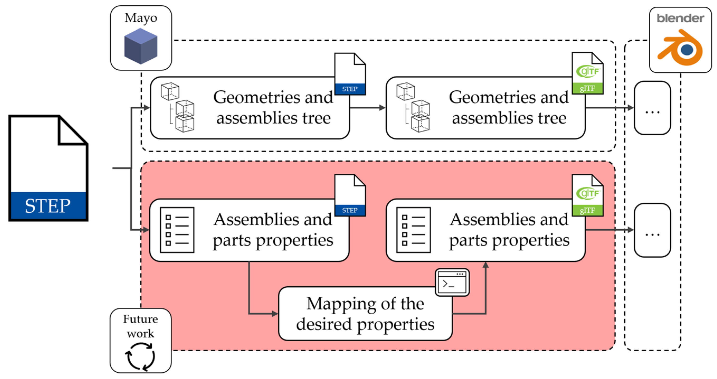
As is often the case in industrial design workflows, the source files used in this case study did not include property data at the part or assembly level. In professional practice, this is a common occurrence, as industrial modeling software is frequently employed primarily for geometric CAD modeling, while non-geometric information is managed separately—either through dedicated data management platforms or directly within spreadsheet applications. This was also the case in the present study, where property data were handled externally and imported via CSV files. Consequently, the development of a dedicated parsing module for extracting and mapping properties from STEP files to IFC entities was not required at this stage. Although the conceptual framework for such a module has been outlined, its implementation has been deferred to future work. Moving forward, the creation of a tool capable of both accurately converting geometric data and selectively mapping semantic properties from STEP models in a configurable manner will be critical to achieving a fully integrated and automated conversion pipeline.
In the present work, the only content requiring processing involved the geometric data and hierarchical structure of the assembly tree. For this purpose, Mayo [35], an open-source software application designed for CAD model visualization and conversion, was used. Among the various tools available, Mayo was selected for its flexible export options, particularly its ability to save each object with its corresponding Instance Name or Product Name or both. The decision to export using the Instance Name proved to be strategic, as this identifier serves as a unique key within the CAD model structure and forms the basis for the automated association of properties from the CSV files in the current workflow. When both names are selected, Mayo combines them into a single Name property formatted as “Product Name [Instance Name]”. However, in the present case study, the Product Name was deemed redundant, as it often duplicated the Instance Name, resulting in unnecessarily long identifiers without adding meaningful information. The STEP-to-glTF conversion workflow is illustrated in Figure 8. Geometric data integrity was verified by overlaying the original STEP model and the exported glTF model within Mayo, confirming accurate alignment. From an information standpoint, the assembly hierarchy is preserved during the export process. The only omitted element is the Product Name, which was not selected during export due to its limited relevance in this specific context.
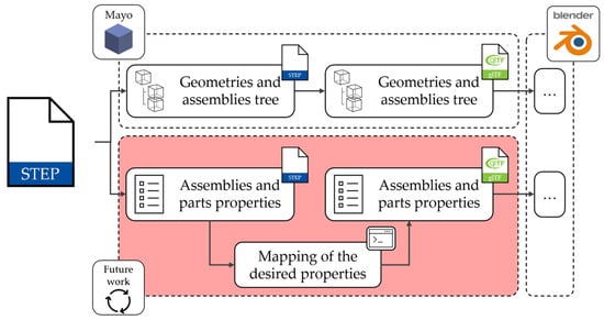
Figure 8.
Mayo workflow to convert a STEP file without assembly and part properties in glTF.
3.2.4. glTF to IFC: Blender Add-On
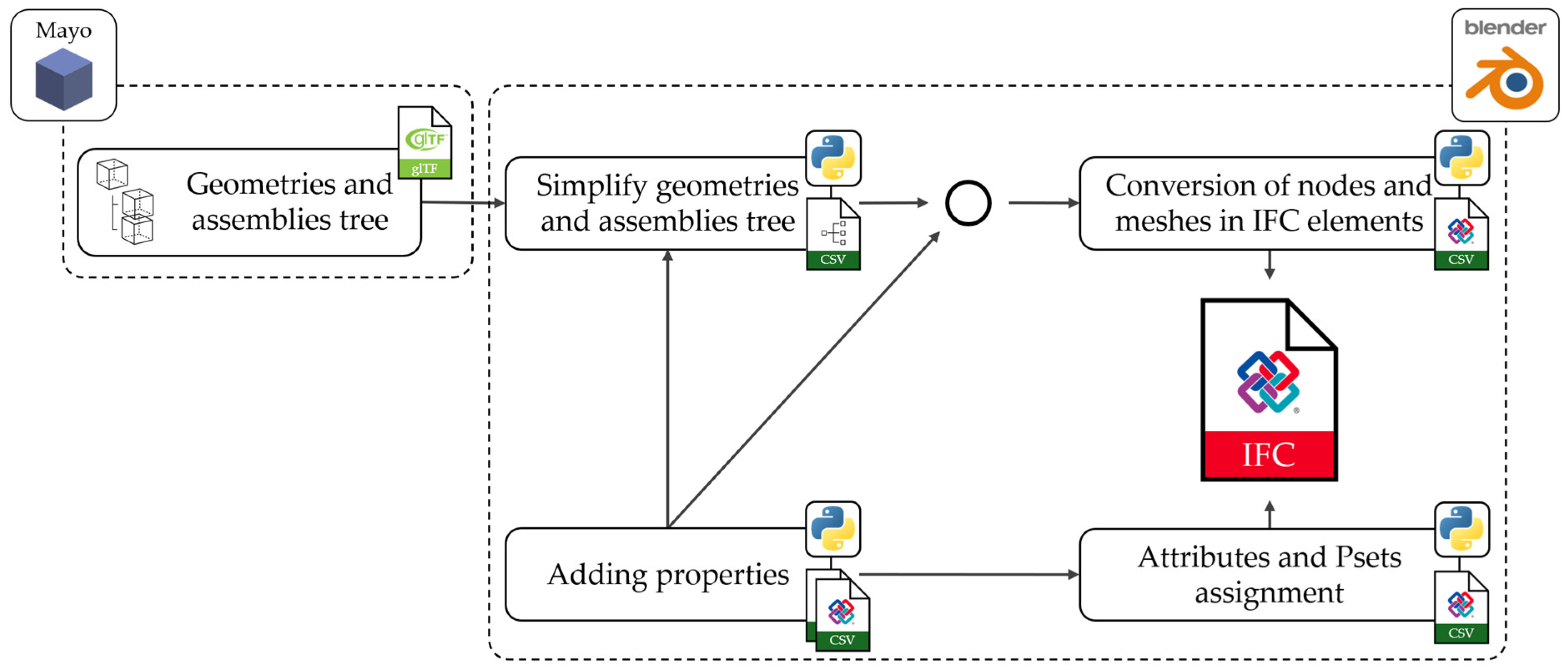
A custom add-on for Blender [36] was developed, featuring an intuitive user interface to manage the conversion process according to the workflow illustrated in Figure 9. The process begins with the import of a glTF-format file into Blender. Then, by processing two separate CSV files, the workflow proceeds with the simplification of geometries and the hierarchical structure of assemblies, based on the data contained in the first CSV (related to simplification) and the conversion of the meshes into IFC elements, complete with attributes and Property Sets derived from the second CSV file containing the semantic IFC data.
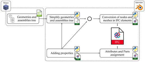
Figure 9.
Workflow to convert a glTF file to IFC using the developed add-on for Blender.
Blender supports the development of add-ons with customizable user interfaces, enabling the creation of intuitive workflows that are accessible even to users without specific programming skills. The add-on developed for this work, as illustrated in Figure 10, is structured into two main panels, each containing a set of commands dedicated to the different phases of the conversion process.
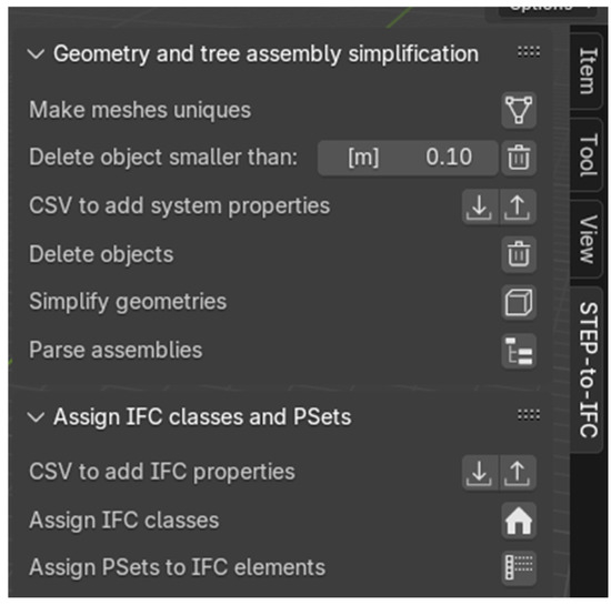
Figure 10.
User interface developed in Blender.
The first panel handles the simplification of geometries and the hierarchical structure of assemblies through the following commands:
- Make meshes unique: Blender allows for the instantiation of objects based on the same mesh to optimize memory usage by applying spatial transformations (translation, rotation, and scaling). However, this approach is incompatible with subsequent processing steps that require the merging and transformation of meshes. Therefore, the script generates independent copies of the meshes, making them individually editable.
- Delete small objects: This command automatically deletes all objects with dimensions smaller than a defined threshold along the X, Y, and Z axes, removing negligible components (e.g., screws, bolts, flanges). This step is not mandatory, and targeted object deletion can still be performed in a later phase.
- CSV to add system properties: A CSV file is generated containing hierarchical information about the parts within the assembly tree. The user is asked to fill in three columns: “To be deleted”, “To be simplified”, and “To be grouped under”. The first column indicates if a part should be removed; the second specifies whether the geometry should be simplified using a bounding box; the third defines the destination assembly for grouping and merging parts, as shown in Table 3.
Table 3. CSV with simplification information. All codes listed in the “Level” column correspond to Instance Names associated with assemblies and components of the Elettra 2.0 light machine used in the case study.
- Delete objects: This removes all meshes marked as “Yes” in the “To be deleted” column of the imported CSV. Subsequently, assemblies without content are deleted to reduce scene complexity.
- Simplify geometries: This replaces meshes marked as “Yes” in the “To be simplified” column of the CSV with their corresponding bounding boxes while preserving the original material.
- Parse assemblies: This groups the meshes under the assemblies defined in the “To be grouped under” column of the CSV. Meshes belonging to the same assembly are then merged into a single object, further optimizing the hierarchical structure.
This second section focuses on the assignment of IFCs and associated properties through the following commands:
- CSV to add IFC properties: generates a CSV file containing all meshes with their respective paths in the assembly tree. The user must specify the IFC class to assign to each object, the Predefined Type, and, if necessary (in the case of USERDEFINED), the Object Type. In addition, users can assign Property Sets (PSets) and corresponding properties by editing or adding columns formatted as PSet_Name/Prop_Name. By replacing PSet_Name with the desired property set and Prop_Name with the target property, it is then possible to populate the property values for all relevant elements, as illustrated in Table 4.
Table 4. CSV file containing IFC-related information. All codes listed in the “Level” column correspond to Instance Names associated with assemblies and components of the Elettra 2.0 light machine used in the case study.
- Assign IFCs: assigns the specified IFC, Predefined Type, and, if required, Object Type to each mesh, according to the CSV content.
- Assign PSets to IFC elements: assigns PSets and properties to the IFC elements in accordance with the content of the CSV. If multiple properties belong to the same PSet, they are correctly grouped under the same PSet, in compliance with the IFC standard. If a PSet is not assignable to a specific IFC class, it will not be considered.
3.3. Results Analysis
Given the multiple possible approaches to implementing this framework, it is essential to evaluate and compare their performance to identify the most effective tools and workflows. By conducting data-driven performance assessments and extending the comparison to include qualitative indicators—such as ease of use, integration capabilities, and user experience—it becomes possible to determine the most suitable solution.
As shown in Table 5, the geometric compression ratio is particularly significant, with a reduction mean in the number of vertices and faces by 91.41% and 90.54%, respectively, a decrease in the total number of objects by 99.05%, and a decrease in the file size of 85.97%. The average time required to complete the entire process, from the conversion of the STEP file into glTF format to the final export in IFC format, is approximately 254 s, a duration considered fully acceptable for practical applications.
Table 5.
Performance analysis. The experimentation was carried out on a laptop equipped with an Intel i7-11800H processor, an RTX A3000 GPU, and 32 GB of RAM. All codes “ESAC00X.Y” in column correspond to Instance Names associated with assemblies of the Elettra 2.0 light machine used in the case study.
The most time-consuming phase of the compilation of CSV files represents a limitation of this study. Due to the high variability of influencing factors, this phase was excluded from the timing analysis, as it would not allow for a consistent or meaningful comparison across cases. This operation, typically carried out using spreadsheet software, is highly dependent on the user’s proficiency in applying filtering, grouping, and bulk editing operations across large datasets. The decision to adopt the CSV format was driven by its wide adoption, flexibility, and its ability to support fast data input, particularly when used with an adequate level of expertise. If all relevant properties were embedded directly within the STEP model, included in the CSV file from the outset, or managed within a dedicated information management system during the design phase, this approach would become significantly more scalable and would overcome this limitation. Such integration would enhance its applicability in professional contexts by streamlining the data preparation process and reducing reliance on manual input.
Finally, the size of the resulting IFC files remains sufficiently compact to ensure usability even on mid-range hardware systems, without compromising overall performance. The validity of the generated IFC files was verified using multiple platforms. In addition to visualization and inspection in Blender with the Bonsai extension, the files were tested in BIMvision [37] to confirm the presence of both geometric and informational data, in IfcQuickBrowser [38] to ensure correct assignment of classes and properties, and in Autodesk Navisworks Manage [39] to overlay the IFC model with the STEP model to verify alignment through original geometry and bounding box comparison.
4. Discussion
This framework establishes a structured method for assigning precise IFCs and properties to components. By aligning with the original function and semantics of the components, the framework provides fine-grained control over the data transformation process. This not only ensures semantic fidelity but also allows for flexible adaptation across diverse project requirements and digital workflows. Rather than serving as a simple format converter, the framework operates as a bridge between industrial and AEC sector design logic.
The practical application of the framework presents several advantages. First, the exclusive use of widely adopted open-source tools—such as Blender—makes the procedure reproducible, accessible, and sustainable. Second, the ability to develop a clear and functional user interface, accessible even to users without programming skills, supports its widespread use in both academic and professional settings.
Despite the numerous benefits offered by the framework, some limitations remain that require further development. One important area for future work concerns the completion of the functional branch dedicated to mapping properties from STEP to glTF format, which is not yet fully implemented. A significant limitation of the current approach lies in the geometric representation of meshes, which are exported to IFC using tessellated geometry. Specifically, meshes are encoded as IfcPolygonalFaceSet entities, with surfaces described through lists of coordinates (IfcCartesianPointList3D) for each vertex. While this ensures a faithful geometric representation, it also leads to a substantial increase in the size of the resulting IFC file due to the large number of points stored. For this reason, the development of alternative strategies for geometry export—aimed at improved efficiency—is required. These strategies may involve the use of more compact representation methods, such as Constructive Solid Geometry (CSG), sweep geometries, Boundary Representation (BRep), and tessellation, all supported by IFC [40]. For tessellated representation, enhanced simplification techniques can be applied to reduce the number of vertices while maintaining sufficient geometric and information quality. Another limitation is the time-consuming nature of manually compiling CSV files. To enhance scalability, automated procedures must be developed to streamline this step and reduce user input requirements. Lastly, as the framework is designed to be adaptable, it will be essential to conduct comparative test campaigns using different tools, libraries, methodologies, and representation logics. The aim is to assess the impact of each approach both in terms of computational performance and the quality and compactness of the resulting IFC file.
5. Conclusions
This work contributes by identifying the key issues, current state of the art, and challenges in integrating the industrial and civil design domains through open standards such as STEP and IFC. A systematic literature review revealed a limited number of relevant studies, many of which are outdated and do not reflect the latest versions of the standards, thus highlighting a clear gap in the literature. Furthermore, the reviewed studies consistently emphasize the lack of practical solutions and the urgent need for interoperable, open-source tools capable of addressing the fragmentation within the AEC sector. To bridge this gap, a methodological framework has been developed to enable structured data conversion from STEP to IFC-SPF, specifically tailored to meet the needs of civil engineering workflows. This framework should not be seen as a simple conversion tool but rather as a system capable of adapting industrial product logic to the information requirements of the AEC domain, with strong potential for application in both academic research and professional practice. Its compatibility with various libraries, tools, and operational logics ensures broad portability and integration across diverse digital environments. An operational implementation of the framework has been developed using open-source tools, such as Blender with the Bonsai extension, and developing an add-on with an intuitive user interface, making it accessible even to users without specialized programming skills. Results from this case study demonstrate precise control over the transformation of industrial model data into IFC entities and PropertySets, along with a significant reduction in computational load achieved through unnecessary component deletions, geometric and informational simplification strategies, and IFC and property assignment.
Author Contributions
Conceptualization, D.A. and C.Z.; methodology, D.A. and C.Z.; software, D.A.; resources, C.Z.; validation, D.A.; investigation, D.A.; data curation, D.A.; writing—original draft preparation, D.A.; writing—review and editing, D.A. and C.Z.; visualization, D.A.; supervision, C.Z.; project administration, C.Z.; funding acquisition, C.Z. All authors have read and agreed to the published version of the manuscript.
Funding
This research was funded by DM 117/2023.
Data Availability Statement
The models and data used in this study are the property of Elettra Sincrotrone Trieste S.C.p.A. and cannot be shared publicly due to privacy and confidentiality restrictions.
Acknowledgments
The authors would like to thank Elettra Sincrotrone Trieste S.C.p.A. for their technical support, for providing the materials used in this case study, and for granting permission to publish selected images of mechanical components from the Elettra 2.0 project. During the preparation of this manuscript/study, the author(s) used ChatGPT4 and DeepL Translator for the purposes of translation and grammar and spelling check. The authors have reviewed and edited the output and take full responsibility for the content of this publication.
Conflicts of Interest
The authors declare no conflicts of interest.
Abbreviations
The following abbreviations are used in this manuscript:
| AEC | Architectural, Engineering and Construction |
| AP | Application Protocol |
| API | Application Programming Interface |
| BIM | Building Information Model |
| CAD | Computer-Aided Design |
| glTF | Graphics Library Transmission Format |
| IFC | Industry Foundation Classes |
| IFC-SPF | IFC STEP Physical File |
| IGES | Initial Graphics Exchange Specification |
| JSON | JavaScript Object Notation |
| JT | Jupiter Tessellation |
| PDM | Product Data Management |
| PMI | Product Manufacturing Information |
| QIF | Quality Information Framework |
| STEP | STandard for the Exchange of Product data |
| STL | STereo Lithography interface format |
References
- ISO 10303-21; Industrial Automation Systems and Integration—Product Data Representation and Exchange. International Organization for Standardization: Geneva, Switzerland, 2016.
- ISO 16739-1; Industry Foundation Classes (IFC) for Data Sharing in the Construction and Facility Management Industries. International Organization for Standardization: Geneva, Switzerland, 2024.
- Nzetchou, S.; Durupt, A.; Remy, S.; Eynard, B. Semantic Enrichment Approach for Low-Level CAD Models Managed in PLM Context: Literature Review and Research Prospect. Comput. Ind. 2022, 135, 103575. [Google Scholar] [CrossRef]
- Feeney, A.B.; Frechette, S.P.; Srinivasan, V. A Portrait of an ISO STEP Tolerancing Standard as an Enabler of Smart Manufacturing Systems. J. Comput. Inf. Sci. Eng. 2015, 15, 021001. [Google Scholar] [CrossRef]
- Lu, Y.; Huang, H.; Liu, C.; Xu, X. Standards for Smart Manufacturing: A Review; IEEE: Vancouver, BC, Canada, 2019; pp. 73–78. [Google Scholar]
- Xiao, J.; Anwer, N.; Durupt, A.; Le Duigou, J.; Eynard, B. Information Exchange Standards for Design, Tolerancing and Additive Manufacturing: A Research Review. Int. J. Interact. Des. Manuf. (IJIDeM) 2018, 12, 495–504. [Google Scholar] [CrossRef]
- Lu, Y.; Xu, X.; Wang, L. Smart Manufacturing Process and System Automation—A Critical Review of the Standards and Envisioned Scenarios. J. Manuf. Syst. 2020, 56, 312–325. [Google Scholar] [CrossRef]
- ISO 14306-1; Industrial Automation Systems and Integration—JT File Format Specification for 3D Visualization. International Organization for Standardization: Geneva, Switzerland, 2024.
- Katzenbach, A.; Handschuh, S.; Vettermann, S. JT Format (ISO 14306) and AP 242 (ISO 10303): The Step to the Next Generation Collaborative Product Creation; Springer: Dresden, Germany, 2013; pp. 41–52. [Google Scholar]
- ISO 23952; Automation Systems and Integration—Quality Information Framework (QIF)—An Integrated Model for Manufacturing Quality Information. International Organization for Standardization: Geneva, Switzerland, 2020.
- Ram, P.S.; Deepak Lawrence, K. Implementation of Quality Information Framework (QIF): Towards Automatic Generation of Inspection Plan from Model-Based Definition (MBD) of Parts. In Proceedings of the Industry 4.0 and Advanced Manufacturing; Chakrabarti, A., Arora, M., Eds.; Springer: Singapore, 2021; pp. 127–138. [Google Scholar]
- Laakso, M.; Kiviniemi, A. The IFC Standard: A Review of History, Development, and Standardization. ITcon 2012, 17, 134–161. [Google Scholar]
- buildingSMART Technical IFC Formats. Available online: https://technical.buildingsmart.org/standards/ifc/ifc-formats/ (accessed on 9 April 2025).
- Farinha, F.; Gonçalves, R.J.; Garção, A.S. Integration of Cooperative Production and Distributed Design in AEC. Adv. Eng. Softw. 2007, 38, 772–779. [Google Scholar] [CrossRef]
- Yang, Q.Z.; Zhang, Y. Semantic Interoperability in Building Design: Methods and Tools. Comput.-Aided Des. 2006, 38, 1099–1112. [Google Scholar] [CrossRef]
- Yang, D.; Eastman, C.M. A Rule-Based Subset Generation Method for Product Data Models. Comput.-Aided Civ. Infrastruct. Eng. 2007, 22, 133–148. [Google Scholar] [CrossRef]
- Gielingh, W. An Assessment of the Current State of Product Data Technologies. Comput.-Aided Des. 2008, 40, 750–759. [Google Scholar] [CrossRef]
- Rowley, J.; Slack, F. Conducting a Literature Review. Manag. Res. News 2004, 27, 31–39. [Google Scholar] [CrossRef]
- Ji, Y.; Borrmann, A.; Beetz, J.; Obergrießer, M. Exchange of Parametric Bridge Models Using a Neutral Data Format. J. Comput. Civ. Eng. 2013, 27, 593–606. [Google Scholar] [CrossRef]
- Fillinger, S.; Esche, E.; Tolksdorf, G.; Welscher, W.; Wozny, G.; Repke, J.-U. Data Exchange for Process Engineering—Challenges and Opportunities. Chem. Ing. Tech. 2019, 91, 256–267. [Google Scholar] [CrossRef]
- Smith, M. Curating Architectural 3D CAD Models. IJDC 2009, 4, 98–106. [Google Scholar] [CrossRef]
- McMillan, A.J.; Swindells, N.; Archer, E.; McIlhagger, A.; Sung, A.; Leong, K.; Jones, R. A Review of Composite Product Data Interoperability and Product Life-Cycle Management Challenges in the Composites Industry. Adv. Manuf. Polym. Compos. Sci. 2017, 3, 130–147. [Google Scholar] [CrossRef]
- ISO 13584-42; Industrial Automation Systems and Integration. International Organization for Standardization: Geneva, Switzerland, 2010.
- Swindells, N. The Representation and Exchange of Material and Other Engineering Properties. Data Sci. J. 2009, 8, 190–200. [Google Scholar] [CrossRef]
- STEP Tools AIM EXPRESS Text: STEP Schemas. Available online: https://steptools.com/stds/stp_aim/html/ (accessed on 9 April 2025).
- STEP Tools AIM: STEP Integrated Definitions Diagram. Available online: https://steptools.com/stds/stp_expg/aim.html (accessed on 9 April 2025).
- Lipman, R.R.; Astheimer, R. STEP File Analyzer and Viewer. Available online: https://www.nist.gov/services-resources/software/step-file-analyzer-and-viewer (accessed on 9 April 2025).
- Gu, P.; Chan, K. Product Modelling Using Step. Comput.-Aided Des. 1995, 27, 163–179. [Google Scholar] [CrossRef]
- Ungerer, M.; Rosché, P. Usage Guide for the STEP PDM Schema V1.2. Available online: https://www.mbx-if.org/home/wp-content/uploads/2024/05/pdmug_release4_3.pdf (accessed on 9 April 2025).
- Blender Foundation. Blender. Available online: https://www.blender.org/ (accessed on 11 April 2025).
- Malta, A.; Farinha, T.; Cardoso, A.J.M.; Mendes, M. Survey on the Use of BIM Methodology for Railway 3D Modeling. Discov. Appl. Sci. 2024, 6, 657. [Google Scholar] [CrossRef]
- Bonsai. Available online: https://bonsaibim.org/index.html (accessed on 11 April 2025).
- Izawa, R.; Koga, M. An Extension of glTF for Robot Description. In Proceedings of the 2019 19th International Conference on Control, Automation and Systems (ICCAS), Jeju, Republic of Korea, 15–18 October 2019; pp. 1010–1014. [Google Scholar]
- The Khronos® 3D Formats Working Group glTFTM 2.0 Specification. Available online: https://registry.khronos.org/glTF/specs/2.0/glTF-2.0.html#foreword (accessed on 9 April 2025).
- Delorme, H. Mayo. Available online: https://github.com/fougue/mayo (accessed on 9 April 2025).
- Avogaro, D. STEP-to-IFC. Available online: https://github.com/Daavogaro/STEP-to-IFC (accessed on 9 April 2025).
- Datacomp IT Sp. z o.o. BIMvision 2025. Available online: https://bimvision.eu/download/ (accessed on 9 April 2025).
- G.E.M. Team Solutions GmbH & Co. KG. IfcQuickBrowser. Available online: https://www.team-solutions.de/programming/lang_endownloadslang_enlang_dedownloadslang_de/ (accessed on 9 April 2025).
- Autodesk Inc. Autodesk Navisworks Manage 2024. Available online: https://www.autodesk.com/products/navisworks/overview (accessed on 9 April 2025).
- Chen, J.; Clarke, K.C. Modeling Standards and File Formats for Indoor Mapping. In Proceedings of the Proceedings of the 3rd International Conference on Geographical Information Systems Theory, Applications and Management; SCITEPRESS—Science and Technology Publications, Porto, Portugal, 27–28 April 2017; pp. 268–275. [Google Scholar]


Disclaimer/Publisher’s Note: The statements, opinions and data contained in all publications are solely those of the individual author(s) and contributor(s) and not of MDPI and/or the editor(s). MDPI and/or the editor(s) disclaim responsibility for any injury to people or property resulting from any ideas, methods, instructions or products referred to in the content. |
© 2025 by the authors. Licensee MDPI, Basel, Switzerland. This article is an open access article distributed under the terms and conditions of the Creative Commons Attribution (CC BY) license (https://creativecommons.org/licenses/by/4.0/).