Computational Modeling of Skull Bone Structures and Simulation of Skull Fractures Using the YEAHM Head Model


 ,
,  ,
,  and
and 
Abstract
1. Introduction
2. Materials and Methods
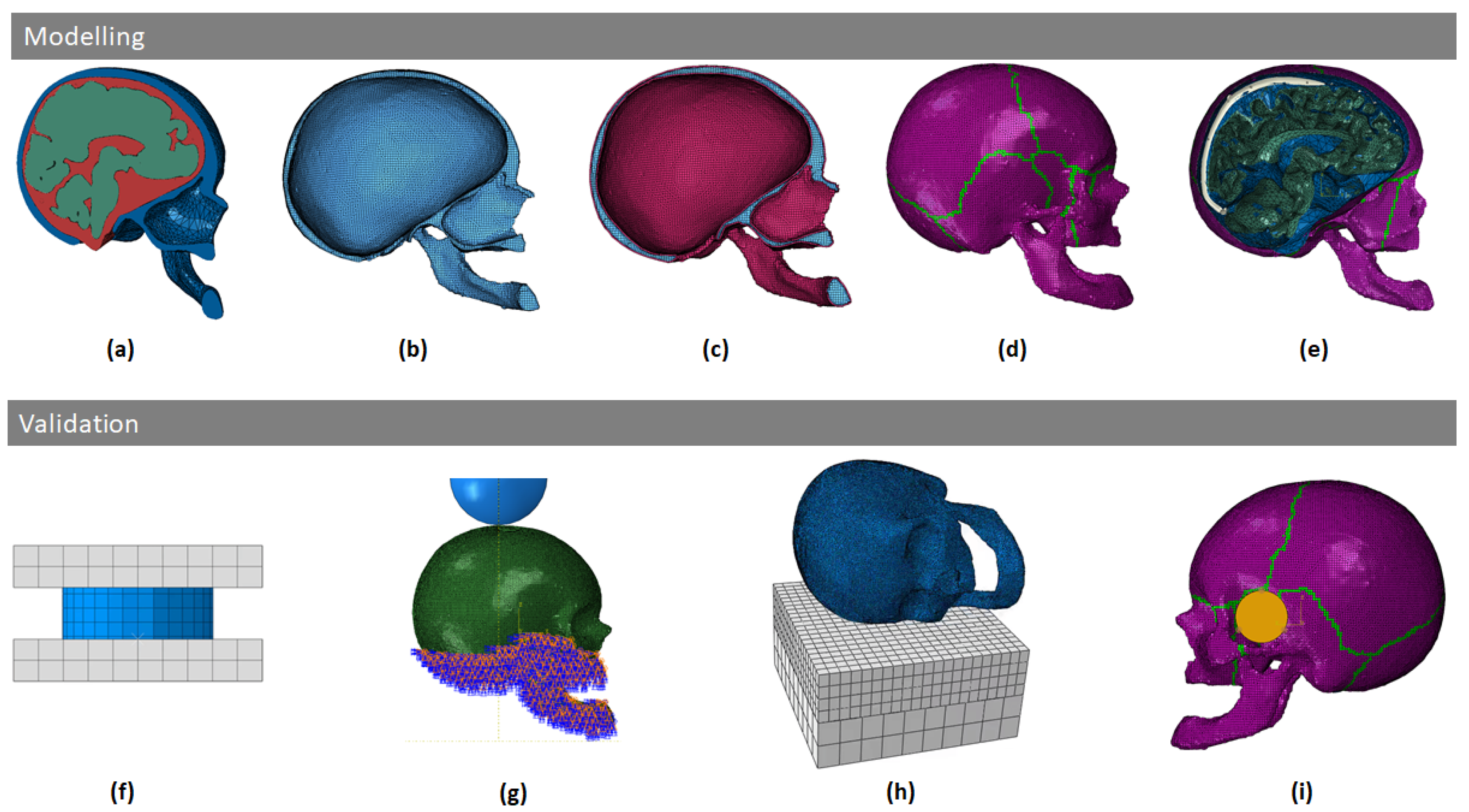
2.1. Skull Modeling
- Construction of the model: with solid finite elements it is possible to quickly make geometrical adjustments to the model and adapt zones more easily than in the case of shells. In addition, since the head is also a layered structure itself (meninges, skull, scalp, etc.), solid elements make it easier to model additional layers in future works.
- Solids also have the advantages of handling double contact better and have a more accurate description of the stress gradient over the thickness, contrary to shells based on plane stress assumptions. Full 3D material laws can be employed without simplifying assumptions like in the case of shells.
- Solid elements are more appropriate than shell elements to study the fracture phenomena of the skull.
2.1.1. Geometrical Modeling
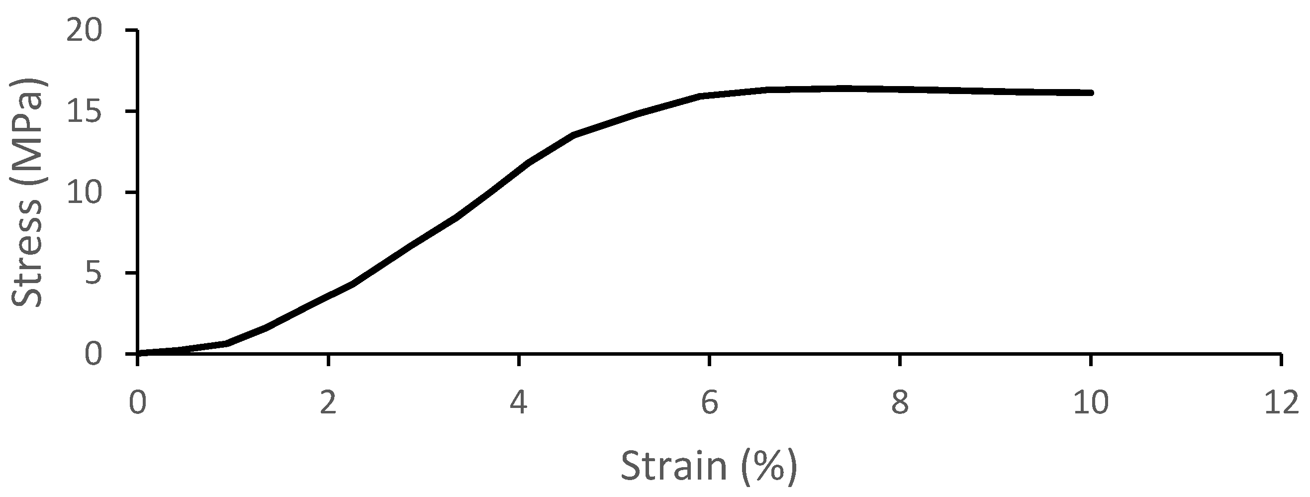
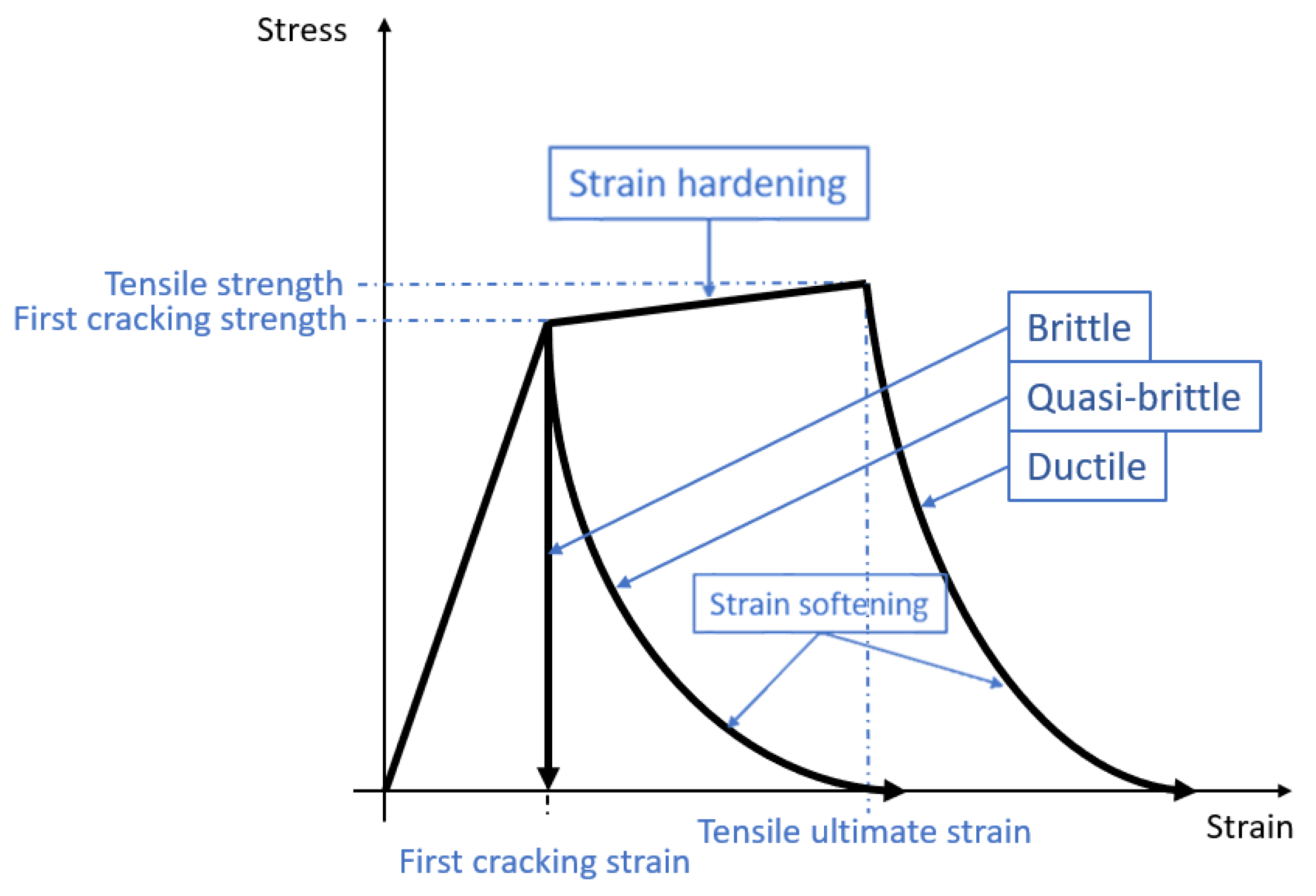
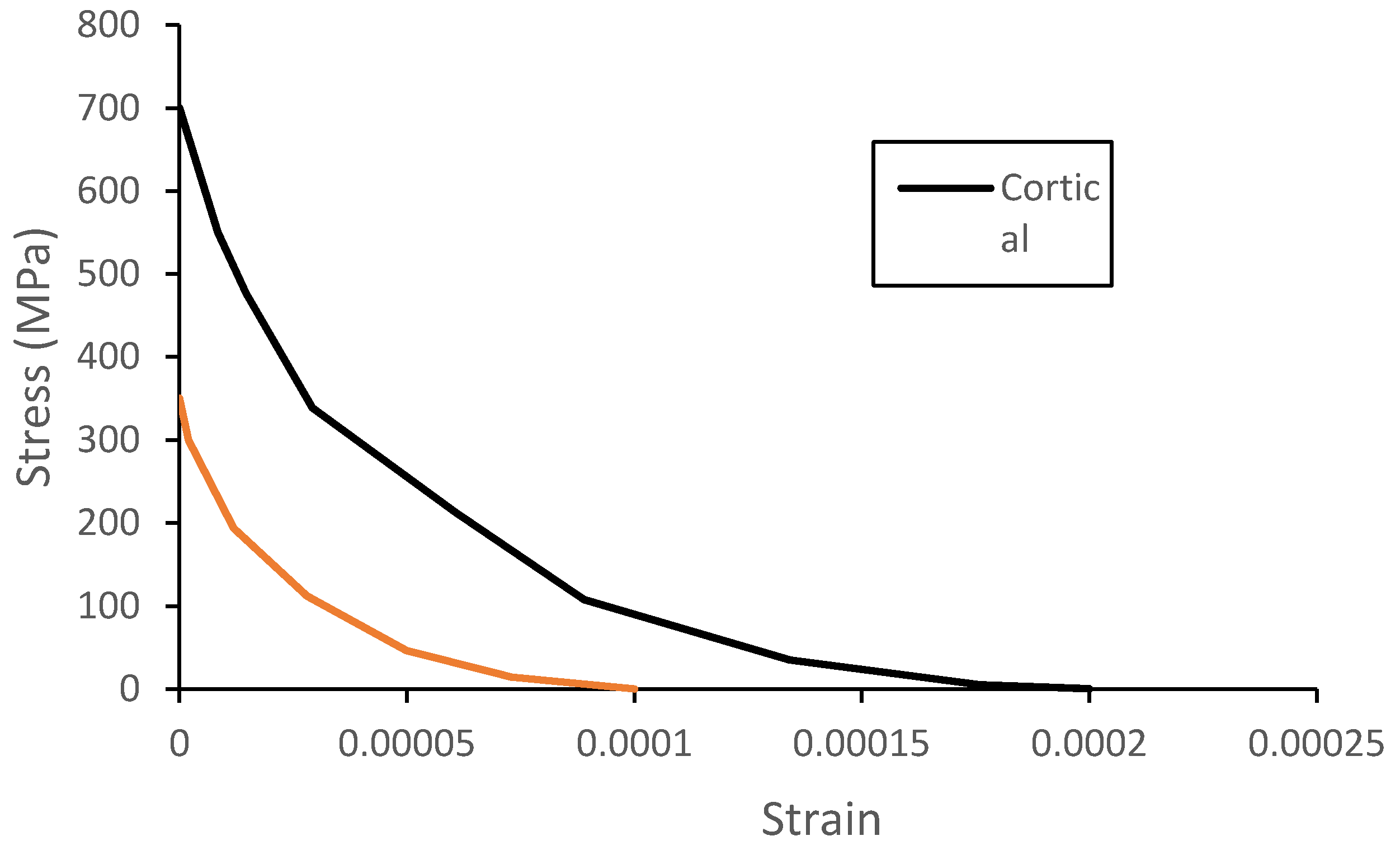
2.1.2. Material Modeling
2.2. Skull Model Validation
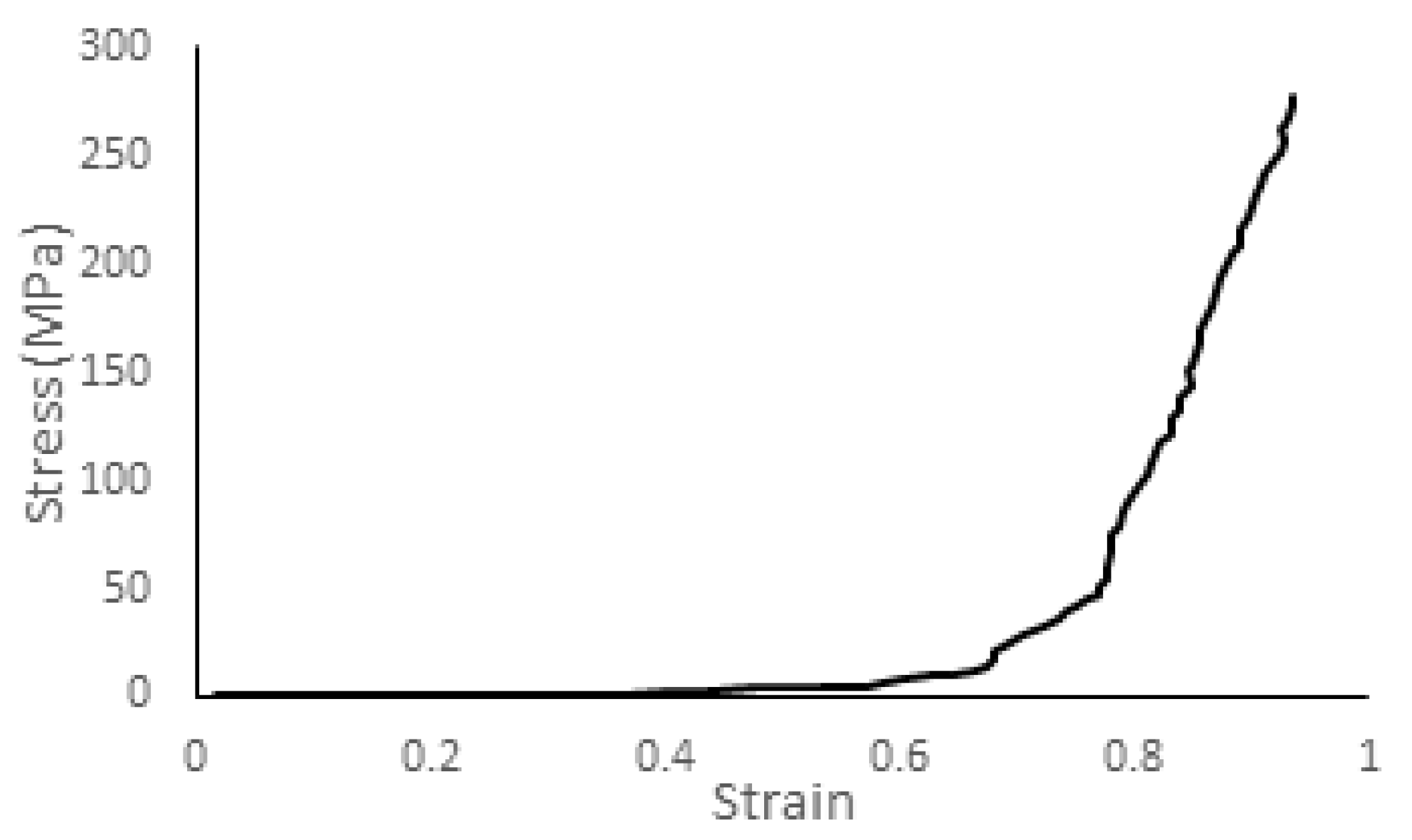
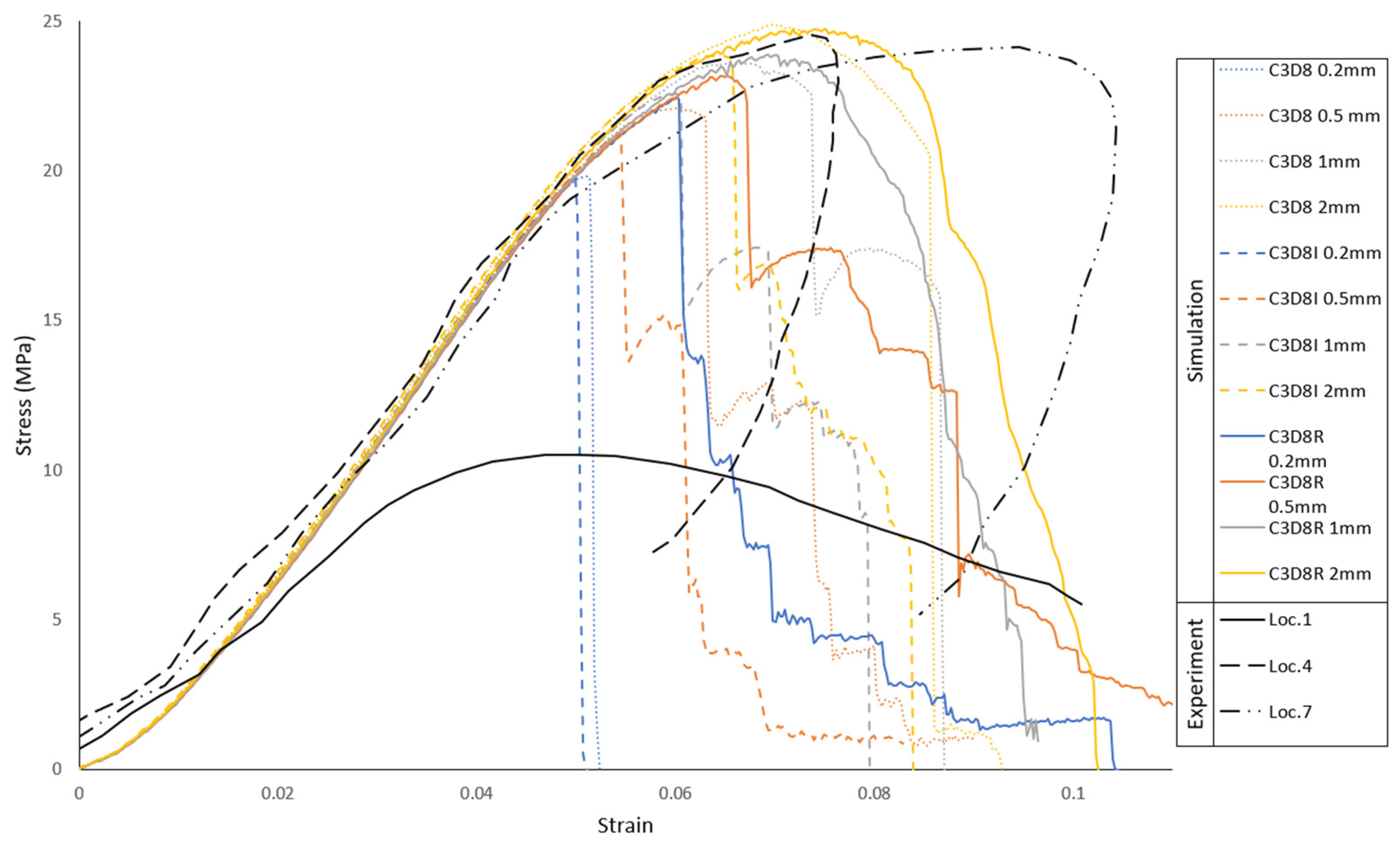
2.2.1. Trabecular Bone Compression—Local Material Validation
2.2.2. Skull Vertex Impact Experiment—Blunt Trauma from Direct Impact against a Stationary Skull
2.2.3. Lateral Head Impact Experiment—Three Impacts at Different Velocities Simulating Falls
2.2.4. Blunt Ballistic Temporo-Parietal Head Impacts
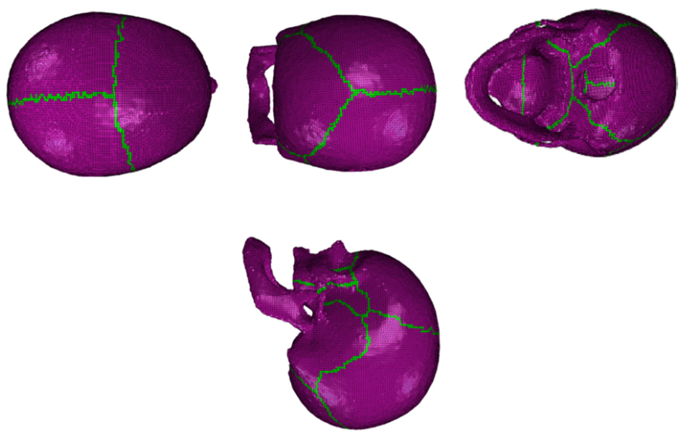
3. Results
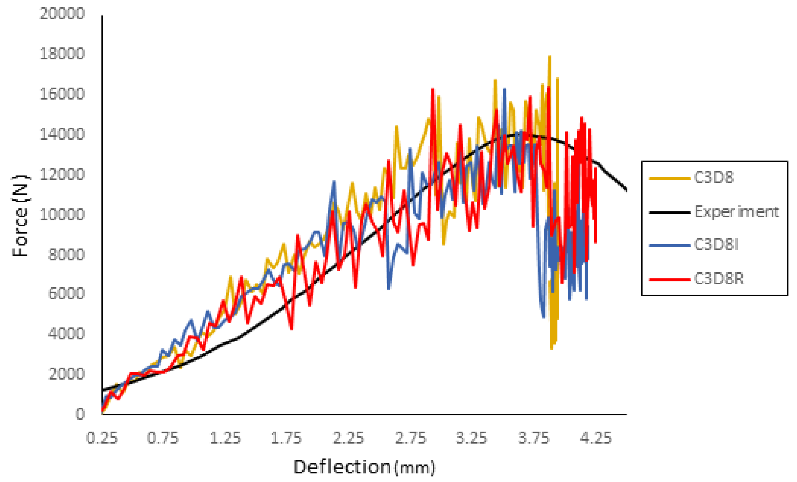
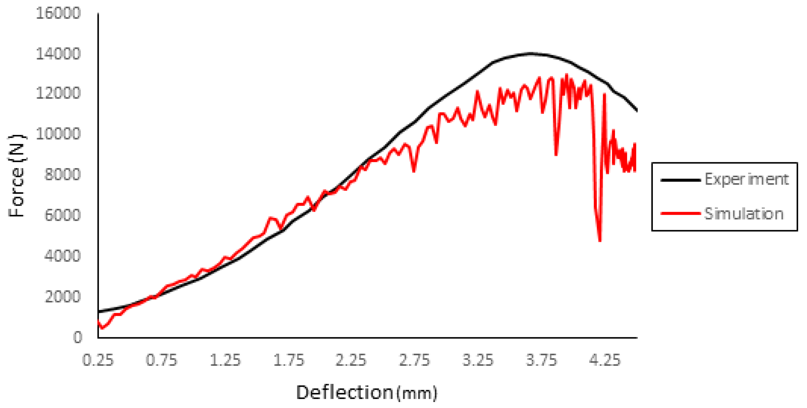
3.1. Trabecular Bone Compression—Local Material Validation
3.2. Skull Vertex Impact Experiment—Blunt Trauma from Direct Impact against Stationary Skull
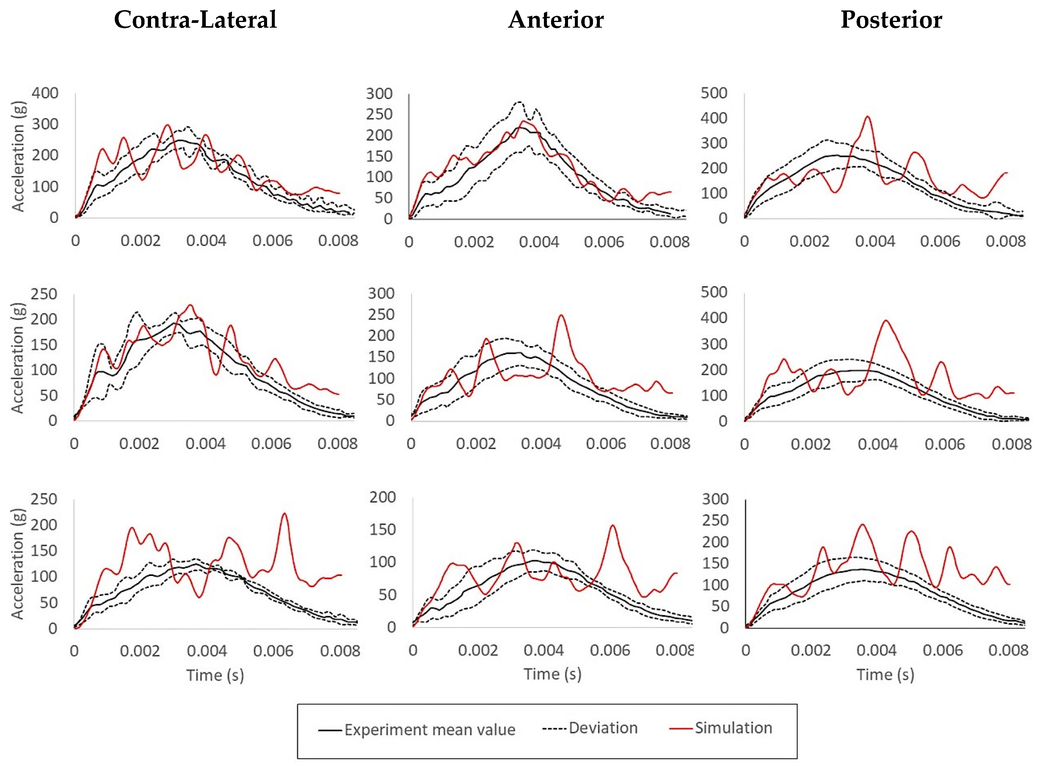
3.3. Lateral Head Impact Experiment—Three Impacts at Different Velocities Simulating Falls
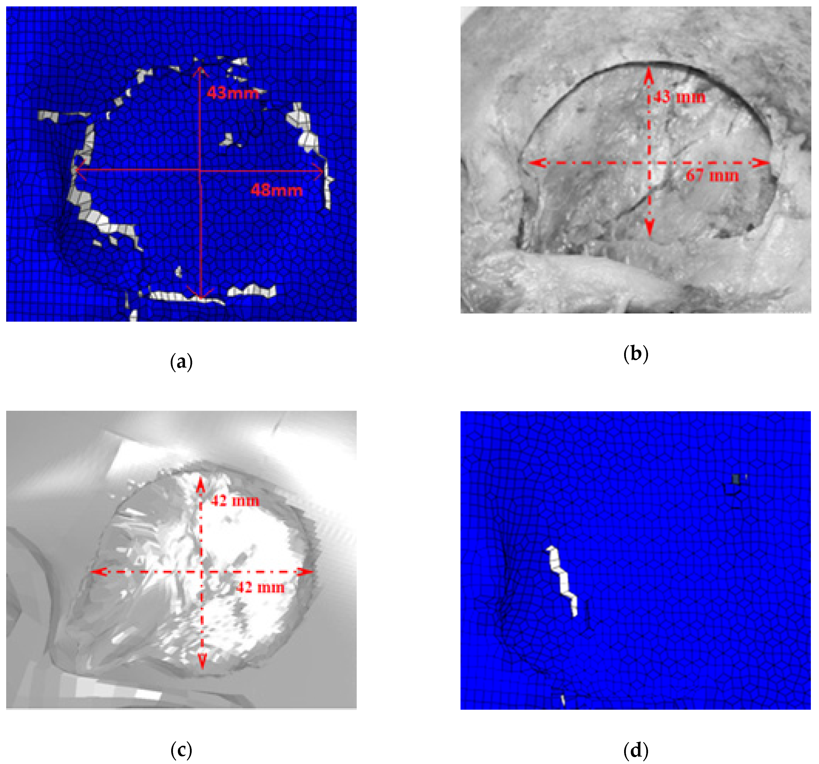
3.4. Blunt Ballistic Temporo-Parietal Head Impacts
4. Conclusions
Author Contributions
Funding
Conflicts of Interest
References
- World Health Organization Road Traffic Injuries. Available online: https://www.who.int/news-room/fact-sheets/detail/road-traffic-injuries (accessed on 14 July 2020).
- Eurostat Accidents at Work Statistics—Statistics Explained. Available online: https://ec.europa.eu/eurostat/statistics-explained/index.php?title=Accidents_at_work_statistics#Incidence_rates (accessed on 14 July 2020).
- Granacher, R.P., Jr. Traumatic Brain Injury: Methods for Clinical and Forensic Neuropsychiatric Assessment, 3rd ed.; CRC Press: Boca Raton, FL, USA, 2015. [Google Scholar]
- Mendelow, A.D.; Teasdale, G.; Jennett, B.; Bryden, J.; Hessett, C.; Murray, G. Risks of intracranial haematoma in head injured adults. BMJ 1983, 287, 1173–1176. [Google Scholar] [CrossRef]
- Hubbard, R.P. Flexure of layered cranial bone. J. Biomech. 1971, 4, 251–263. [Google Scholar] [CrossRef]
- Gould, J.A., III. Fisioterapia na Ortopedia e na Medicina do Esporte, 2nd ed.; Manole: São Paulo, Brazil, 2003. [Google Scholar]
- Matsumoto, T.; Mihashi, H. JCI-DFRCC summary report on dfrcc terminologies and application concepts. In Proceedings of the JCI International Workshop on Ductile Fiber Reinforced Cementitious Composites, Takayama, Japan, 21–22 October 2002; pp. 59–66. [Google Scholar]
- Lynnerup, N.; Astrup, J.G.; Sejrsen, B. Thickness of the human cranial diploe in relation to age, sex and general body build. Head Face Med. 2005, 1, 13. [Google Scholar] [CrossRef] [PubMed]
- Lillie, E.M.; Urban, J.E.; Lynch, S.K.; Weaver, A.A.; Stitzel, J.D. Evaluation of Skull Cortical Thickness Changes With Age and Sex From Computed Tomography Scans. J. Bone Miner. Res. 2016, 31, 299–307. [Google Scholar] [CrossRef] [PubMed]
- Ptak, M.; Ratajczak, M.; Kwiatkowski, A.; Sawicki, M.; Wilhelm, J.; Fernandes, F.A.O.; Druszcz, A. Investigation of biomechanics of skull structures damages caused by dynamic loads. Acta Bioeng. Biomech. 2018, 20, 143–150. [Google Scholar] [PubMed]
- Herring, S.; Ochareon, P. Bone—Special problems of the craniofacial region. Orthod. Craniofacial Res. 2005, 8, 174–182. [Google Scholar] [CrossRef]
- Khonsari, R.H.; Olivier, J.; Vigneaux, P.; Sanchez, S.; Tafforeau, P.; Ahlberg, P.E.; Di Rocco, F.; Bresch, D.; Corre, P.; Ohazama, A.; et al. A mathematical model for mechanotransduction at the early steps of suture formation. Proc. R. Soc. B Biol. Sci. 2013, 280, 2012–2670. [Google Scholar] [CrossRef]
- Malczyk, A.; Bauer, K.; Juhra, C.; Schick, S. Head Injuries in Bicyclists and Associated Crash Characteristics. In Proceedings of the Internacional Research Council on Biomechanics of Injury, Berlin, Germany, 10–12 September 2014. [Google Scholar]
- Delille, R.; Lesueur, D.; Potier, P.; Drazetic, P.; Markiewicz, E. Experimental study of the bone behaviour of the human skull bone for the development of a physical head model. Int. J. Crashworthiness 2007, 12, 101–108. [Google Scholar] [CrossRef]
- Dempsey, N.; Blau, S. Evaluating the evidentiary value of the analysis of skeletal trauma in forensic research: A review of research and practice. Forensic Sci. Int. 2020, 307, 110–140. [Google Scholar] [CrossRef]
- Yu, C.; Wang, F.; Wang, B.; Li, G.; Li, F. A Computational Biomechanics Human Body Model Coupling Finite Element and Multibody Segments for Assessment of Head/Brain Injuries in Car-To-Pedestrian Collisions. Int. J. Environ. Res. Public Health 2020, 17, 492. [Google Scholar] [CrossRef]
- Fernandes, F.A.O.; Alves de Sousa, R.J.; Ptak, M. Application of numerical methods for accident reconstruction and forensic analysis. In Head Injury Simulation in Road Traffic Accidents. SpringerBriefs in Applied Sciences and Technology; Springer: Cham, Switzerland, 2018. [Google Scholar] [CrossRef]
- Ren, L.; Wang, D.; Liu, X.; Yu, H.; Jiang, C.; Hu, Y. Influence of Skull Fracture on Traumatic Brain Injury Risk Induced by Blunt Impact. Int. J. Environ. Res. Public Health 2020, 17, 2392. [Google Scholar] [CrossRef] [PubMed]
- Toma, M.; Chan-Akeley, R.; Lipari, C.; Kuo, S.-H. Mechanism of Coup and Contrecoup Injuries Induced by a Knock-Out Punch. Math. Comput. Appl. 2020, 25, 22. [Google Scholar] [CrossRef]
- Persson, J.; Helgason, B.; Engqvist, H.; Ferguson, S.J.; Persson, C. Stiffness and strength of cranioplastic implant systems in comparison to cranial bone. J. Cranio-Maxillofac. Surg. 2018, 46, 418–423. [Google Scholar] [CrossRef] [PubMed]
- Marcián, P.; Narra, N.; Borák, L.; Chamrad, J.; Wolff, J. Biomechanical performance of cranial implants with different thicknesses and material properties: A finite element study. Comput. Biol. Med. 2019, 109, 43–52. [Google Scholar] [CrossRef] [PubMed]
- Hardy, C.H.; Marcal, P.V. Elastic analysis of a skull. J. Appl. Mech. Trans. ASME 1973, 40, 838–842. [Google Scholar] [CrossRef]
- Shugar, T.A. Transient structural response of the linear skull-brain system. In Proceedings of the SAE Technical Papers; SAE International: San Diego, CA, USA, 1975. [Google Scholar]
- Tse, K.M.; Lim, S.P.; Tan, V.B.C.; Lee, H.P. A Review of Head Injury and Finite Element Head Models. Am. J. Eng. Technol. Soc. 2014, 1, 28–52. [Google Scholar]
- Giudice, J.S.; Zeng, W.; Wu, T.; Alshareef, A.; Shedd, D.F.; Panzer, M.B. An Analytical Review of the Numerical Methods used for Finite Element Modeling of Traumatic Brain Injury. Ann. Biomed. Eng. 2019, 47, 1855–1872. [Google Scholar] [CrossRef]
- Sahoo, D.; Deck, C.; Yoganandan, N.; Willinger, R. Anisotropic composite human skull model and skull fracture validation against temporo-parietal skull fracture. J. Mech. Behav. Biomed. Mater. 2013, 28, 340–353. [Google Scholar] [CrossRef]
- Yoganandan, N.; Zhang, J.; Pintar, F.A. Force and acceleration corridors from lateral head impact. Traffic Inj. Prev. 2004, 5, 368–373. [Google Scholar] [CrossRef]
- Asgharpour, Z.; Baumgartner, D.; Willinger, R.; Graw, M.; Peldschus, S. The validation and application of a finite element human head model for frontal skull fracture analysis. J. Mech. Behav. Biomed. Mater. 2014, 33, 16–23. [Google Scholar] [CrossRef]
- Verschueren, P.; Delye, H.; Depreitere, B.; Van Lierde, C.; Haex, B.; Berckmans, D.; Verpoest, I.; Goffin, J.; Vander Sloten, J.; Van der Perre, G. A new test set-up for skull fracture characterisation. J. Biomech. 2007, 40, 3389–3396. [Google Scholar] [CrossRef] [PubMed]
- Cai, Z.; Xia, Y.; Bao, Z.; Mao, H. Creating a human head finite element model using a multi-block approach for predicting skull response and brain pressure. Comput. Methods Biomech. Biomed. Eng. 2019, 22, 169–179. [Google Scholar] [CrossRef] [PubMed]
- Yoganandan, N.; Pintar, F.A.; Sances, A.; Walsh, P.R.; Ewing, C.L.; Thomas, D.J.; Snyder, R.G. Biomechanics of Skull Fracture. J. Neurotrauma 1995, 12, 659–668. [Google Scholar] [CrossRef]
- Raymond, D.; Van Ee, C.; Crawford, G.; Bir, C. Tolerance of the skull to blunt ballistic temporo-parietal impact. J. Biomech. 2009, 42, 2479–2485. [Google Scholar] [CrossRef] [PubMed]
- Chamrad, J.; Marcián, P.; Borák, L. On the level of computational model of a human skull: A comparative study. Appl. Comput. Mech. 2018, 12, 5–16. [Google Scholar] [CrossRef][Green Version]
- Wilhelm, J.; Ptak, M.; Fernandes, F.A.O.; Kubicki, K.; Kwiatkowski, A.; Ratajczak, M.; Sawicki, M.; Szarek, D. Injury Biomechanics of a Child’s Head: Problems, Challenges and Possibilities with a New aHEAD Finite Element Model. Appl. Sci. 2020, 10, 4467. [Google Scholar] [CrossRef]
- Fernandes, F.A.O.; Tchepel, D.; Alves de Sousa, R.J.; Ptak, M. Development and validation of a new finite element human head model: Yet another head model (YEAHM). Eng. Comput. (Swansea, Wales) 2018, 35, 477–496. [Google Scholar] [CrossRef]
- Boruah, S.; Henderson, K.; Subit, D.; Salzar, R.S.; Shender, B.S.; Paskoff, G. Response of Human Skull Bone to Dynamic Compressive Loading. In Proceedings of the IRCOBI Conference, Gothenburg, Sweden, 11–13 September 2013. [Google Scholar]
- Huang, J.; Raymond, D.; Shen, W.; Stuhmiller, J.; Crawford, G.; Bir, C. Development and validation of a subject-specific finite element model for skull fracture assessment. In Proceedings of the ASME 2011 International Mechanical Engineering Congress and Exposition, IMECE 2011, Denver, CO, USA, 11–17 November 2011; American Society of Mechanical Engineers (ASME): Denver, CO, USA, 2011; Volume 2, pp. 31–40. [Google Scholar]
- Migueis, G.F.J.; Fernandes, F.A.O.; Ptak, M.; Ratajczak, M.; Alves de Sousa, R.J. Detection of bridging veins rupture and subdural haematoma onset using a finite element head model. Clin. Biomech. 2019, 63, 104–111. [Google Scholar] [CrossRef]
- Costa, J.M.C.; Fernandes, F.A.O.; Alves de Sousa, R.J. Prediction of subdural haematoma based on a detailed numerical model of the cerebral bridging veins. J. Mech. Behav. Biomed. Mater. 2020, 111, 103976. [Google Scholar] [CrossRef]
- Monea, A.G.; Baeck, K.; Verbeken, E.; Verpoest, I.; Sloten, J.V.; Goffin, J.; Depreitere, B. The biomechanical behaviour of the bridging vein-superior sagittal sinus complex with implications for the mechanopathology of acute subdural haematoma. J. Mech. Behav. Biomed. Mater. 2014, 32, 155–165. [Google Scholar] [CrossRef]
- Depreitere, B.; Van Lierde, C.; Vander Sloten, J.; Van Audekercke, R.; Van Der Perre, G.; Plets, C.; Goffin, J. Mechanics of acute subdural hematomas resulting from bridging vein rupture. J. Neurosurg. 2006, 104, 950–956. [Google Scholar] [CrossRef] [PubMed]
- Nahum, A.M.; Smith, R.; Ward, C.C. Intracranial pressure dynamics during head impact. In Proceedings of the SAE Technical Papers; SAE International: New Orleans, LA, USA, 1977. [Google Scholar]
- Hardy, W.N.; Foster, C.D.; Mason, M.J.; Yang, K.H.; King, A.I.; Tashman, S. Investigation of Head Injury Mechanisms Using Neutral Density Technology and High-Speed Biplanar X-ray. In Proceedings of the SAE Technical Papers; SAE International: San Antonio, TX, USA, 2001. [Google Scholar]
- Fernandes, F.A.O.; Alves de Sousa, R.J.; Ptak, M. Validation of YEAHM. In Head Injury Simulation in Road Traffic Accidents; SpringerBriefs in Applied Sciences and Technology; Springer: Cham, Switzerland, 2018; pp. 41–58. [Google Scholar] [CrossRef]
- Tadepalli, S.C.; Erdemir, A.; Cavanagh, P.R. Comparison of hexahedral and tetrahedral elements in finite element analysis of the foot and footwear. J. Biomech. 2011, 44, 2337–2343. [Google Scholar] [CrossRef] [PubMed]
- Marjoux, D.; Baumgartner, D.; Deck, C.; Willinger, R. Head injury prediction capability of the HIC, HIP, SIMon and ULP criteria. Accid. Anal. Prev. 2008, 40, 1135–1148. [Google Scholar] [CrossRef] [PubMed]
- Fernandes, F.A.O.; de Sousa, R.J.A.; Ptak, M. A damage model for the simulation of crack initiation and propagation in automotive windshield laminated glass structures. Int. J. Crashworthiness 2020. [Google Scholar] [CrossRef]
- Vorst, M.V.; Chan, P.; Zhang, J.; Yogandan, N.; Pintar, F. A new biomechanically-based criterion for lateral skull fracture. Annu. Proc. Assoc. Adv. Automot. Med. 2004, 48, 181–195. [Google Scholar]
- ElGawady, M.; Booker, A.J.; Dawood, H.M. Seismic Behavior of Posttensioned Concrete-Filled Fiber Tubes. J. Compos. Constr. 2010, 14, 616–628. [Google Scholar] [CrossRef]
- Trotta, A.; Clark, J.M.; McGoldrick, A.; Gilchrist, M.D.; Annaidh, A.N. Biofidelic finite element modelling of brain trauma: Importance of the scalp in simulating head impact. Int. J. Mech. Sci. 2020, 173, 105448. [Google Scholar] [CrossRef]


| Tissue Type | Density (kg/m3) | Young Modulus (MPa) | Poisson’s Ratio |
|---|---|---|---|
| Cortical | 1900 | 20,000 | 0.21 |
| Sutures | 2100 | 15,000 | 0.3 |
| Bone Structure | Thickness (mm) | Standard Deviation (mm) |
|---|---|---|
| Outer Table | 0.76 | ±0.29 |
| Inner Table | 0.35 | ±0.15 |
| Trabeculae | 5.08 | ±2.01 |
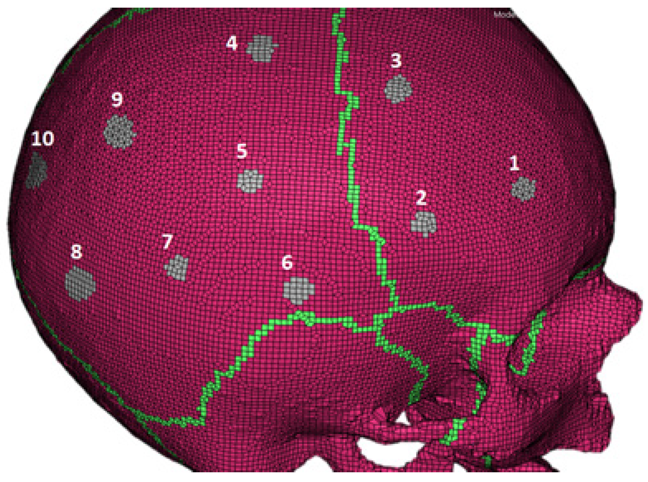
| Location | 1 | 2 | 3 | 4 | 5 | 6 | 7 | 8 | 9 | 10 |
|---|---|---|---|---|---|---|---|---|---|---|
| Skull Thickness (mm) | 6.1 | 7.1 | 5.7 | 6.3 | 7.3 | 7.8 | 6.3 | 7.3 | 6.9 | 5 |
| Deviation from the Average (mm) | 0.1 | 0.9 | 0.5 | 0.1 | 1.1 | 1.6 | 0.1 | 1.1 | 0.7 | 1.2 |
© 2020 by the authors. Licensee MDPI, Basel, Switzerland. This article is an open access article distributed under the terms and conditions of the Creative Commons Attribution (CC BY) license (http://creativecommons.org/licenses/by/4.0/).
Share and Cite
Barbosa, A.; Fernandes, F.A.O.; Alves de Sousa, R.J.; Ptak, M.; Wilhelm, J. Computational Modeling of Skull Bone Structures and Simulation of Skull Fractures Using the YEAHM Head Model. Biology 2020, 9, 267. https://doi.org/10.3390/biology9090267
Barbosa A, Fernandes FAO, Alves de Sousa RJ, Ptak M, Wilhelm J. Computational Modeling of Skull Bone Structures and Simulation of Skull Fractures Using the YEAHM Head Model. Biology. 2020; 9(9):267. https://doi.org/10.3390/biology9090267
Chicago/Turabian StyleBarbosa, Alcino, Fábio A. O. Fernandes, Ricardo J. Alves de Sousa, Mariusz Ptak, and Johannes Wilhelm. 2020. "Computational Modeling of Skull Bone Structures and Simulation of Skull Fractures Using the YEAHM Head Model" Biology 9, no. 9: 267. https://doi.org/10.3390/biology9090267
APA StyleBarbosa, A., Fernandes, F. A. O., Alves de Sousa, R. J., Ptak, M., & Wilhelm, J. (2020). Computational Modeling of Skull Bone Structures and Simulation of Skull Fractures Using the YEAHM Head Model. Biology, 9(9), 267. https://doi.org/10.3390/biology9090267