Conductive Electrospun Polyaniline/Polyvinylpyrrolidone Nanofibers: Electrical and Morphological Characterization of New Yarns for Electronic Textiles


 ,
, 
Abstract
1. Introduction
2. Materials and Methods
2.1. Materials
2.2. Synthesis of PANI Powders
2.3. Synthesis of t-Boc Protected PANI Powders
2.4. Electrospinning of t-Boc Protected PANI/PVP
2.5. Electrical and Morphological Characterization
3. Results and Discussion
4. Conclusions
Supplementary Materials
Author Contributions
Funding
Conflicts of Interest
References
- Wu, S.; Liu, P.; Zhang, Y.; Zhang, H.; Qin, X. Flexible and conductive nanofiber-structured single yarn sensor for smart wearable devices. Sens. Actuators B Chem. 2017, 252, 697–705. [Google Scholar] [CrossRef]
- Cherenack, K.; Zysset, C.; Kinkeldei, T.; Münzenrieder, N.; Tröster, G. Woven Electronic Fibers with Sensing and Display Functions for Smart Textiles. Adv. Mater. 2010, 22, 5178–5182. [Google Scholar] [CrossRef] [PubMed]
- Müller, C.; Hamedi, M.; Karlsson, R.; Jansson, R.; Marcilla, R.; Hedhammar, M.; Inganäs, O. Woven Electrochemical Transistors on Silk Fibers. Adv. Mater. 2011, 23, 898–901. [Google Scholar] [CrossRef] [PubMed]
- Lee, Y.-H.; Kim, J.-S.; Noh, J.; Lee, I.; Kim, H.J.; Choi, S.; Seo, J.; Jeon, S.; Kim, T.-S.; Lee, J.-Y.; et al. Wearable Textile Battery Rechargeable by Solar Energy. Nano Lett. 2013, 13, 5753. [Google Scholar] [CrossRef]
- Takamatsu, S.; Kobayashi, T.; Shibayama, N.; Miyake, K.; Itoh, T. Fabric pressure sensor array fabricated with die-coating and weaving techniques. Sens Actuators A Phys. 2012, 184, 57–63. [Google Scholar] [CrossRef]
- O’Connor, B.; An, K.H.; Zhao, Y.; Pipe, K.P.; Shtein, M. Fiber Shaped Light Emitting Device. Adv. Mater. 2007, 19, 3897–3900. [Google Scholar] [CrossRef]
- Grancarić, A.M.; Jerković, I.; Koncar, V.; Cochrane, C.; Kelly, F.M.; Soulat, D.; Legrand, X. Conductive polymers for smart textile applications. J. Ind. Text. 2017, 48, 612–642. [Google Scholar] [CrossRef]
- Namgoong, H.; Woo, D.J.; Lee, S.-H. Micro-chemical structure of polyaniline synthesized by self-stabilized dispersion polymerization. Macromol. Res. 2007, 15, 633. [Google Scholar] [CrossRef]
- MacDiarmid, A.G. “Synthetic metals”: A novel role for organic polymers. Curr. Appl. Phys. 2001, 1, 269–279. [Google Scholar] [CrossRef]
- Moutsatsou, P.; Coopman, K.; Smith, M.B.; Georgiadou, S. Conductive PANI fibers and determining factors for the electrospinning window. Polymer 2015, 77, 143–151. [Google Scholar] [CrossRef]
- Boeva, Z.A.; Sergeyev, V.G. Polyaniline: Synthesis, properties, and application. Polym. Sci. Ser. C 2014, 56, 144. [Google Scholar] [CrossRef]
- Cortés, M.T.; Sierra, E.V. Effect of synthesis parameters in polyaniline: Influence on yield and thermal behavior. Polym. Bull. 2006, 56, 37–45. [Google Scholar] [CrossRef]
- Jelmy, E.J.; Ramakrishnan, S.; Devanathan, S.; Rangarajan, M.; Kothurkar, N.K. Optimization of the conductivity and yield of chemically synthesized polyaniline using a design of experiments. J. Appl. Polym. Sci. 2013, 130, 1047–1057. [Google Scholar] [CrossRef]
- Baptista, A.C.; Ropio, I.; Romba, B.; Nobre, J.P.; Henriques, C.; Silva, J.C.; Martins, J.I.; Borges, J.P.; Ferreira, I. Cellulose-based electrospun fibers functionalized with polypyrrole and polyaniline for fully organic batteries. J. Mater. Chem. A 2018, 6, 256. [Google Scholar] [CrossRef]
- Ropio, I.; Baptista, A.C.; Nobre, J.P.; Correia, J.; Belo, F.; Taborda, S.; Morais Faustino, B.M.; Borges, J.P.; Kovalenko, A.; Ferreira, I. Cellulose paper functionalised with polypyrrole and poly(3,4-ethylenedioxythiophene) for paper battery electrodes. Org. Electron. 2018, 62, 530. [Google Scholar] [CrossRef]
- Liu, H.; Kameoka, J.; Czaplewski, D.A.; Craighead, H.G. Polymeric Nanowire Chemical Sensor. Nano Lett. 2004, 4, 671–675. [Google Scholar] [CrossRef]
- Zhu, Y.; Zhang, J.; Zheng, Y.; Huang, Z.; Feng, L.; Jiang, L. Stable, Superhydrophobic, and Conductive Polyaniline/Polystyrene Films for Corrosive Environments. Adv. Funct. Mater. 2006, 16, 568–574. [Google Scholar] [CrossRef]
- Uh, K.; Kim, T.; Lee, C.W.; Kim, J.-M. A Precursor Approach to Electrospun Polyaniline Nanofibers for Gas Sensors. Macromol. Mater. Eng. 2016, 301, 1320–1326. [Google Scholar] [CrossRef]
- Lee, C.-W.; Seo, Y.-H.; Lee, S.-H. A Soluble Polyaniline Substituted with t-BOC: Conducting Patterns and Doping. Macromolecules 2004, 37, 4070–4074. [Google Scholar] [CrossRef]
- Gomes, E.C.; Oliveira, M.A.S. Chemical Polymerization of Aniline in Hydrochloric Acid (HCl) and Formic Acid (HCOOH) Media. Differences Between the Two Synthesized Polyanilines. Am. J. Polym. Sci. 2012, 2, 5–13. [Google Scholar] [CrossRef]
- Boyer, M.I.; Quillard, S.; Rebourt, E.; Louarn, G.; Buisson, J.P.; Monkman, A.; Lefrant, S. Vibrational Analysis of Polyaniline: A Model Compound Approach. J. Phys. Chem. B 1998, 102, 7382–7392. [Google Scholar] [CrossRef]
- Kiefer, W. Recent Advances in linear and nonlinear Raman spectroscopy I. J. Raman Spectrosc. 2007, 38, 1538–1553. [Google Scholar] [CrossRef]
- Pereira da Silva, J.E.; de Faria, D.L.A.; Córdoba de Torresi, S.I.; Temperini, M.L.A. Influence of Thermal Treatment on Doped Polyaniline Studied by Resonance Raman Spectroscopy. Macromolecules 2000, 33, 3077–3083. [Google Scholar] [CrossRef]
- Niaura, G.; Mažeikien, R.; Malinauskas, A. Structural changes in conducting form of polyaniline upon ring sulfonation as deduced by near infrared resonance Raman spectroscopy. Synth. Met. 2004, 145, 105–112. [Google Scholar] [CrossRef]
- Bernard, M.C.; Hugot-Le Goff, A. Quantitative characterization of polyaniline films using Raman spectroscopy: I: Polaron lattice and bipolaron. Electrochim. Acta 2006, 52, 595–603. [Google Scholar] [CrossRef]
- Liu, W.; Zhang, J.; Liu, H. Conductive Bicomponent Fibers Containing Polyaniline Produced via Side-by-Side Electrospinning. Polymers 2019, 11, 954. [Google Scholar] [CrossRef]
- Lin, Y.-W.; Wu, T.-M. Fabrication of water-soluble polyaniline/poly(ethylene oxide)/carbon nanotube electrospun fibers. J. Appl. Polym. Sci. 2012, 126, E123–E129. [Google Scholar] [CrossRef]
- Simotwo, S.K.; Kalra, V. Study of Co-electrospun Nafion and Polyaniline Nanofibers as Potential Catalyst Support for Fuel Cell Electrodes. Electrochim. Acta 2016, 198, 156–164. [Google Scholar] [CrossRef]
- Zhang, Y.; Rutledge, G.C. Electrical Conductivity of Electrospun Polyaniline and Polyaniline-Blend Fibers and Mats. Macromolecules 2012, 45, 4238–4246. [Google Scholar] [CrossRef]


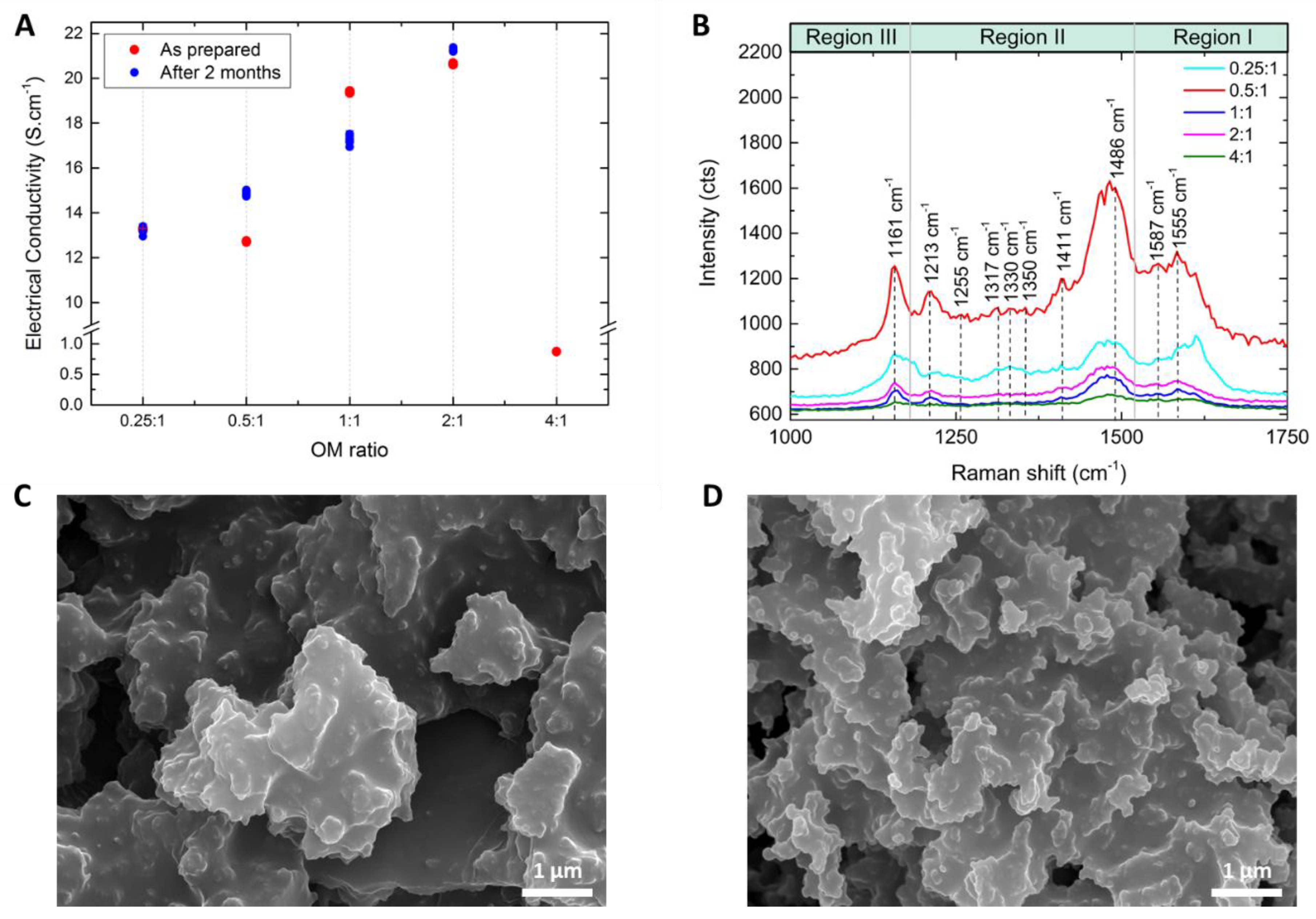
| OM Ratio | 0.25:1 | 0.5:1 | 1:1 | 2:1 | 4:1 |
| Yield (%) | 14 | 27 | 63 | 97 | 91 |
| Conductivity (S·cm−1) As prepared | 13.25 ± 0.13 | 12.87 ± 0.10 | 19.24 ± 0.15 | 20.26 ± 0.05 | 0.873 ± 0.001 |
| Conductivity (S·cm−1) After 2 months | 13.27 ± 0.02 | 12.71 ± 0.02 | 19.38 ± 0.03 | 20.64 ± 0.03 | -- |
| Composition | Methodology | Structure | Conductivity [S·cm−1] | Ref. |
|---|---|---|---|---|
| Camphoric acid doped PANI/PEO | Side-by-side ES | Membrane (2D) | 3.8 × 10⁻⁴ | [26] |
| Camphoric acid doped PANI/PEO | Blend ES | Membrane (2D) | ~10−5 | [26] |
| Sulfonated PANI/PEO | Blend ES | Membrane (2D) | ~10−9 | [27] |
| Sulfonated PANI/PEO/Carbon Nanotubes | Blend ES | Membrane (2D) | ~10−6 | [27] |
| Camphoric acid doped PANI/PEO and Nafion/PEO | Dual ES | Membrane (2D) | 1.4 × 10⁻² (after PEO removing) | [28] |
| Camphor sulfonic acid doped PANI/PEO | Blend ES | Fiber (1D) | 8 (after PEO removing) | [29] |
| Camphor sulfonic acid doped PANI/PMMA | Blend ES | Fiber (1D) | 2 × 10⁻² (after PVDF removing) | [29] |
| Chemical modified PANI | ES | Fiber (1D) | 20 | [18] |
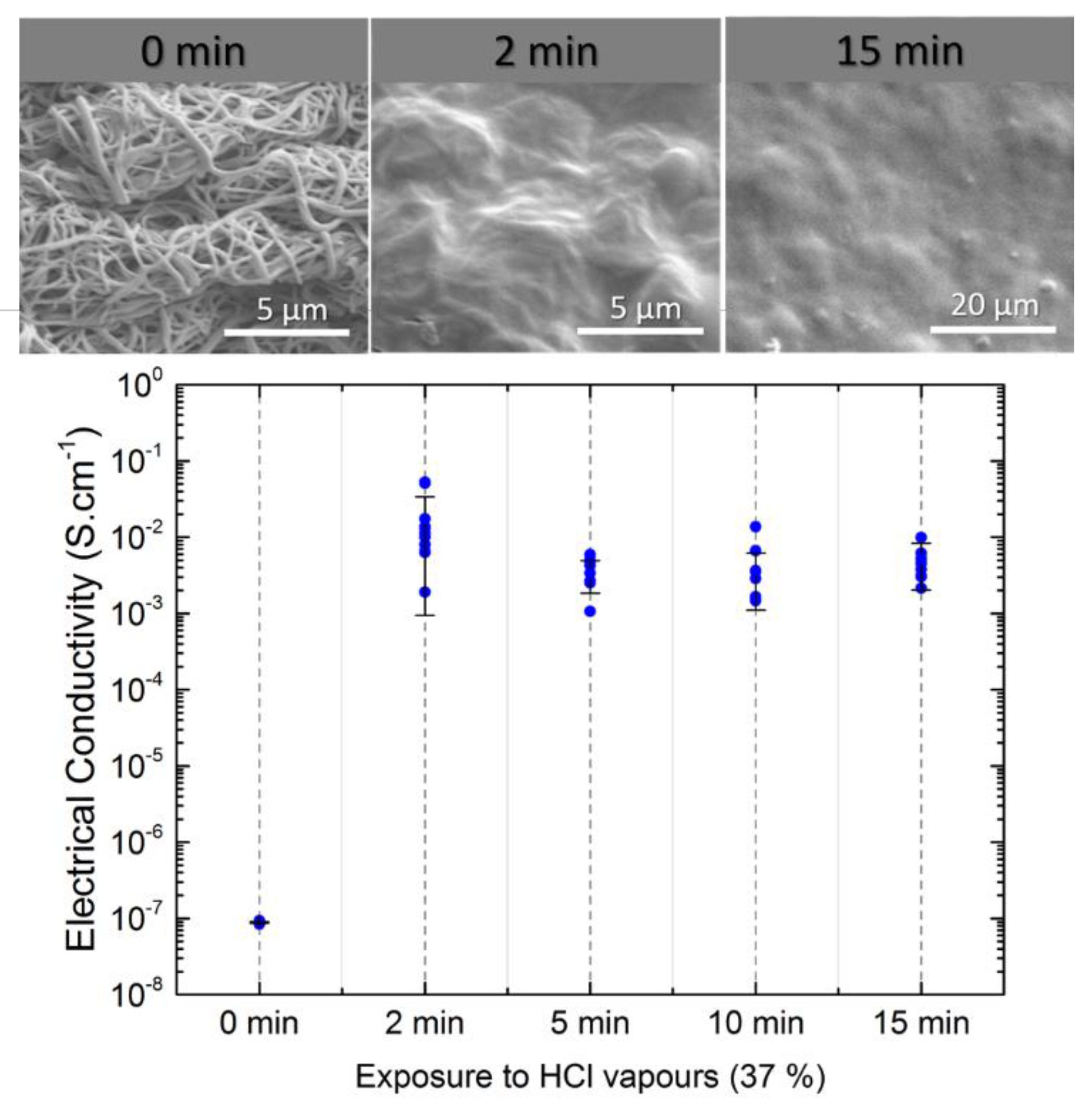
| Chemical modified PANI+PVP | Blend ES | Membrane (2D) | 1.7 × 10⁻² | This work |
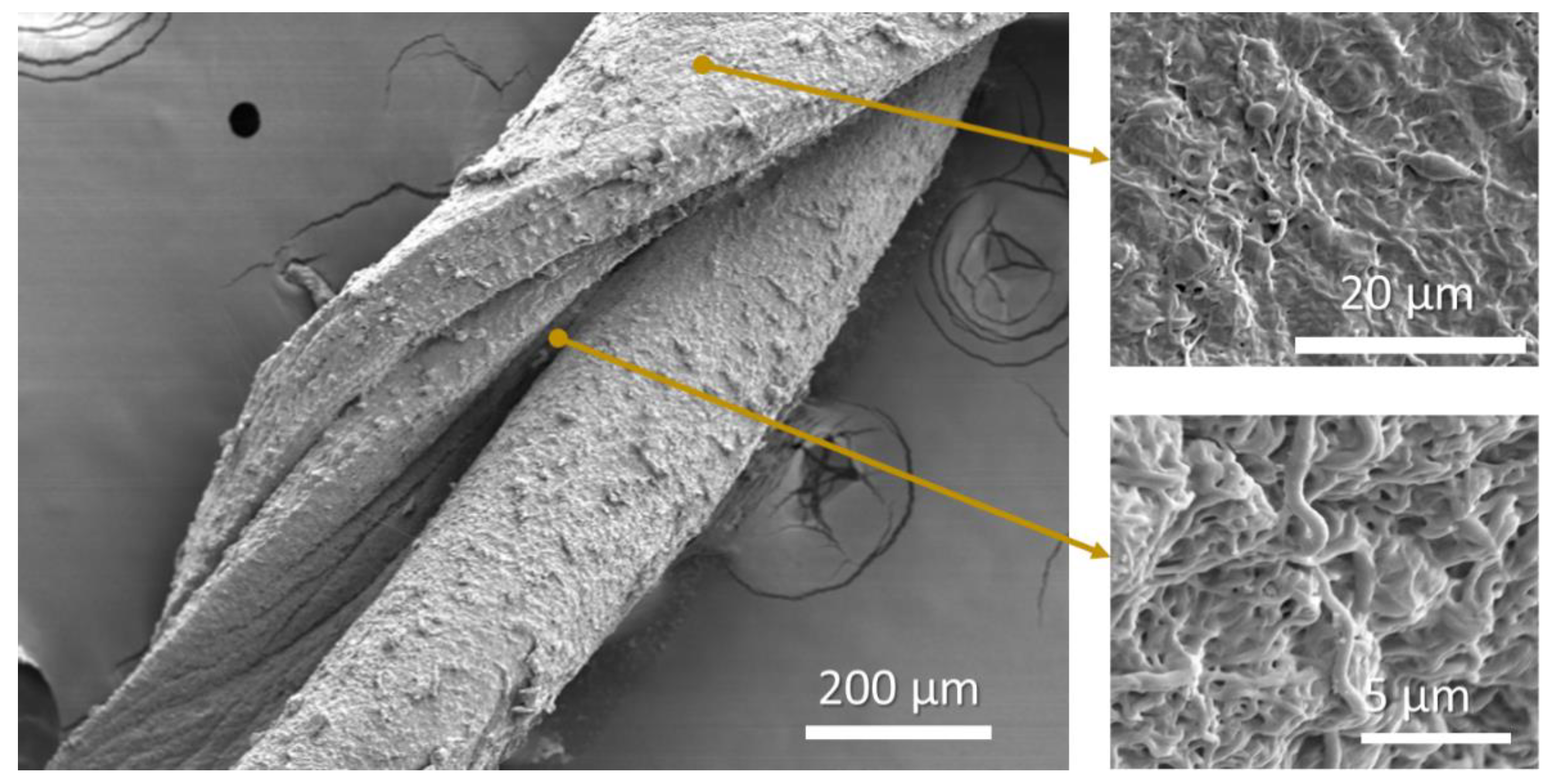
| Chemical modified PANI+PVP | Blend ES | Yarn (1D) | 4.1 × 10⁻⁴ | This work |
© 2020 by the authors. Licensee MDPI, Basel, Switzerland. This article is an open access article distributed under the terms and conditions of the Creative Commons Attribution (CC BY) license (http://creativecommons.org/licenses/by/4.0/).
Share and Cite
Perdigão, P.; Morais Faustino, B.M.; Faria, J.; Canejo, J.P.; Borges, J.P.; Ferreira, I.; Baptista, A.C. Conductive Electrospun Polyaniline/Polyvinylpyrrolidone Nanofibers: Electrical and Morphological Characterization of New Yarns for Electronic Textiles. Fibers 2020, 8, 24. https://doi.org/10.3390/fib8040024
Perdigão P, Morais Faustino BM, Faria J, Canejo JP, Borges JP, Ferreira I, Baptista AC. Conductive Electrospun Polyaniline/Polyvinylpyrrolidone Nanofibers: Electrical and Morphological Characterization of New Yarns for Electronic Textiles. Fibers. 2020; 8(4):24. https://doi.org/10.3390/fib8040024
Chicago/Turabian StylePerdigão, Patrícia, Bruno Miguel Morais Faustino, Jaime Faria, João Paulo Canejo, João Paulo Borges, Isabel Ferreira, and Ana Catarina Baptista. 2020. "Conductive Electrospun Polyaniline/Polyvinylpyrrolidone Nanofibers: Electrical and Morphological Characterization of New Yarns for Electronic Textiles" Fibers 8, no. 4: 24. https://doi.org/10.3390/fib8040024
APA StylePerdigão, P., Morais Faustino, B. M., Faria, J., Canejo, J. P., Borges, J. P., Ferreira, I., & Baptista, A. C. (2020). Conductive Electrospun Polyaniline/Polyvinylpyrrolidone Nanofibers: Electrical and Morphological Characterization of New Yarns for Electronic Textiles. Fibers, 8(4), 24. https://doi.org/10.3390/fib8040024