Abstract
Openings in reinforced concrete (RC) slabs are not commonly prescribed in design codes. Even when they are, they raise concerns regards to the size of the openings and the location of the applied loads. Lack of sufficient information about the load-carrying capacity of the slabs with openings and performance is another concern. Hence, this research addresses the structural behavior of slabs with openings coated with Carbon Fiber Reinforced Polymer (CFRP) sheet. In the experimental part, ten slabs were cast with a dimension of 1000 mm × 530 mm × 25 mm, among which nine slabs had openings and one slab was without opening (control slab). The configuration of the CFRP sheet includes coating in the form of single, double, and triple layers. Experimental results show that the slab with a triple coating of the CFRP layer offers the maximum resistance towards the loading rate. Moreover, with the increase in CFRP layers, the value of deflection is minimized.
1. Introduction
Reinforced concrete (RC) slabs are used as floors in residential buildings, industrial buildings, decks in bridges, and many more. Slabs can be prefabricated and brought to the construction sites or can be made in-situ at the site [1,2]. Openings in the slab are becoming common nowadays in retrofitting of existing structures or even in new structures/buildings during the design stage due to functional requirements from the services engineers, architects, and many more [3,4]. The functional requirements are provision for staircases, elevators, escalators, windows, doors, electrical, heating and ventilation systems. These require openings on floors or walls [4,5]. The effect on structural performance due to small openings is often not considered significant as the ability of the structure to redistribute stresses is anticipated [6,7]. However, for large openings, this is not the case. Large openings bring a lack of ability for the structure to resist the imposed loads or to redistribute it [8]. Therefore, it requires strengthening.
The use of CFRP for strengthening of existing slabs due to openings is common nowadays [8,9,10,11]. However, only a handful of studies have been reported on the structural behavior of slabs with openings, with or without CFRP strengthening [12]. More research into the subject matter is required. Performance of RC slabs with openings strengthened using CFRP is one of the areas that require attention [13]. This research will lead to a better knowledge of the failure mechanism, present design techniques, and effective methods of strengthening the structural behavior of the slabs with an opening [14]. Besides, CFRP reinforcement methods provide a practical cost-efficient design approach. In the past few years, Fiber Reinforced Polymer (FRP) materials have been used extensively as a new construction material [15,16]. They have many advantages such as being lightweight, high strength, nonmagnetic, and noncorrosive [17,18,19]. They have a wide range of potential applications that covers both new and existing structures [20,21]. CFRP is a carbon type of FRP material that is used extensively in the field of structural engineering. CFRP materials have been used for strengthening many structures such as concrete slabs, beams, columns, and walls [4,22]. The flexural capacity of those structures can be increased by bonding these material sheets to the tension side of the structure [23,24,25,26]. In the case of a two-way slab with a low or medium reinforcement ratio, the slab tends to fail in flexure rather than in shear [24]. The flexural capacity of two-way slabs can be increased by using FRP/CFRP [17,20]. Moreover, their use is very desirable due to the ease of handling and installation of these materials.
CFRP materials, currently produced in different configurations, are widely used for the strengthening and retrofitting of concrete structures [12,27]. Recently, research has been directed to characterize the use of CFRP sheets as a flexural reinforcement for strengthening applications. In the study done by [28], CFRP sheets were used as the strengthening material to improve the shear capacity of concrete slabs [29]. It was observed that the CFRP has increased the flexural stiffness and improved the punching shear strength of the slabs. The increase in the flexural capacity has modified the failure from a pure flexural mode to a combined flexure-shear mode or pure punching shear mode [30]. By efficiently binding the CFRP layers to the tension face of slabs, the flexural resistance of the two-way slab can be strengthened. This method of flexural strengthening offers different benefits: minimization of structural expansion and its weight, ease of handling on-site, and excellent resistance to corrosion [31,32]. The connection between concrete and CFRP composite reinforcement at the interface has an important effect on the overall performance of the reinforced framework because the CFRP sheets are attached to the concrete framework. Fewer research was, however, carried out on slab with openings [30,33,34].
Among the literature available on this domain, experimental investigations conducted by [35,36,37,38] demonstrate the advantages of strengthening slabs using rectangular CFRP sheets or thin plates bonded to the tensile face of the slabs. Limam et al. [38] have examined the collapse mechanism and associated load capability for CFRP sheets to strengthen the two-way slabs. Kim et al. [39] conducted research on slabs strengthened with prestressed and non-prestressed CFRP layers. The findings of the tests showed that the ultimate load-carrying ability of slab was increased from 4% to 18% with the CFRP sheets, including an improvement in cracking load of 25% in comparison to the control specimen. Similar research was carried out on slab reinforced with CFRP based on criteria for punching failure [40,41]. Foret and Limam [42] conducted comparative research on the strengthening of two-way slabs composite using externally bonded (EB) and near-surface mounted (NSM) techniques. The tests showed that NSM was more ductile compared to the EB approach. There is also a cost-effective benefit to the NSM approach in comparison with a reduced amount of carbon fibers.
Conversely, there are not many research papers that have investigated how the number of CFRP layers which can affect the structural behavior of the RC slabs with openings. Moreover, the effect of the size of the openings on the structural behavior is an area to be investigated. Therefore, this work aims to evaluate experimentally how the size of openings influences the structural behavior of slabs, and how the number of CFRP layers affects the structural behavior of slabs with various sizes of openings. Based on this, the number of adequate layers of CFRP sheets can be determined and recommended.
2. Methodology
2.1. Experimental Setup
For slab casting, a conventional formwork preparation is required. The formwork is prepared with dimensions of 1000 mm by 530 mm by 25 mm. An 8 mm diameter mild steel round reinforcement bar was fabricated following the design criteria, as shown in Figure 1, Figure 2 and Figure 3 and the height of the concrete cover used is 7 mm. In order to prepare the openings for all nine slabs, the steel reinforcement has been cut as shown in Figure 4, following dimensional length variations of 160 mm by 160 mm, 230 mm by 230 mm, and 320 mm by 320 mm. The mechanical characteristics of cement, reinforcement bar and CFRP used are provided below in Table 1, Table 2 and Table 3, respectively, whereas Table 4 shows the reinforcement bar ratio of the reference RC members.
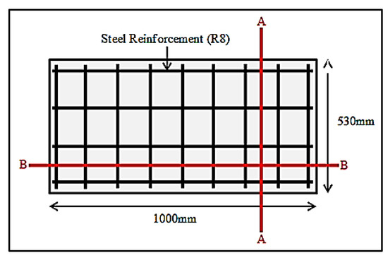
Figure 1.
Slabs steel reinforcement design.
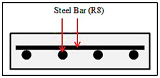
Figure 2.
Cross section A-A.
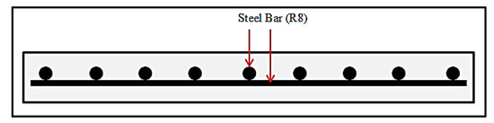
Figure 3.
Cross section B-B.
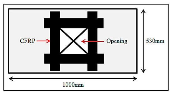
Figure 4.
Slab samples needed.

Table 1.
Characteristics of ordinary Portland cement.
Table 2.
Characteristics of reinforcement bar.
Table 3.
Characteristics of Carbon fiber reinforced polymer.
Table 4.
Reinforcement ratio of the RC members.
Furthermore, strain gauges (SGs) were also installed on the reinforcement bar of the control slab, as shown in Figure 5. Primarily, the centerline has been marked in the reinforcement bar to provide ease in the attachment of SGs. These SGs were attached to the reinforcement bar using super glue. Additionally, SGs, terminal pads, and the exposed wire were covered with silicone glue in order to avoid contact with water.
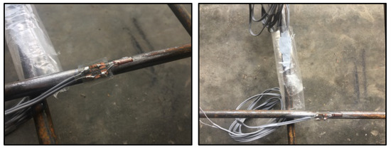
Figure 5.
Attachment of strain gauges.
To ensure the desired strength of the prepared concrete, six cylindrical samples (150 mm × 300 mm) were cast to obtain the test results concerning compressive strength, modulus of elasticity and Poisson’s ratio at day 28. An additional three prism samples (100 mm × 100 mm × 500 mm) were cast to determine the flexural strength of the concrete and subsequently tested for a two-point load system. Afterward, concrete was poured inside the formwork, and the surface of the slab was flattened to ensure a smooth surface finish. Before pouring concrete, the inner part of formwork was greased to provide ease in its removal. The casted samples were then cured for 28 days. Later, CFRP sheets were attached to the slab soffits using epoxy glue as shown in Figure 6. The CFRP sheets were sandwiched between layers of epoxy glue for 24 h to ensure its sufficient bonding strength. As the epoxy glue dried utterly, slabs were painted in white color (except the CFRP region) to ensure the easiness of identifying the crack line on its surface during the testing phase. Lastly, rosettes were attached on the CFRP sheet surface using superglue (dried for 30 min) at 45° for better configuration in all nine slabs with openings as shown in Figure 7. Figure 8 defines the marking of these slab surfaces for two-point load tests at the defined position.
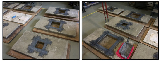
Figure 6.
Attachment of CFRP sheets on the slab soffits.
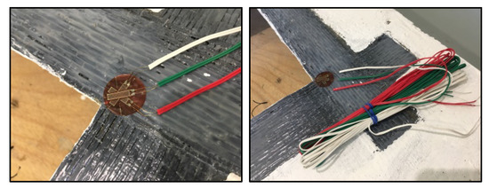
Figure 7.
Attachment of strain rosette on CFRP surface.
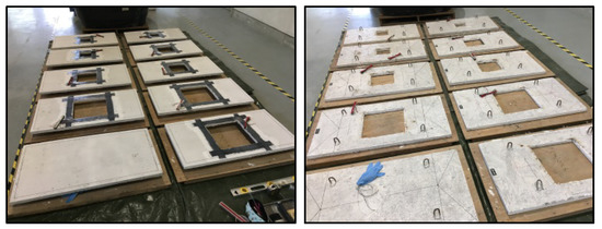
Figure 8.
Marking on the slab soffits and top.
2.2. Testing of Slabs
RC slabs are considered as supported on all sides as they were placed on top of the frame (950 mm by 470 mm). Two-point loading system was applied at 170 mm from both ends of the slab, up to failure, as shown in Figure 9. Figure 10 shows the uniformly varying load configuration adopted for all slabs tested. The applied force was controlled by the loading cell, directly connected to the loading instrument. The purpose behind SGs installation was to obtain the reinforcement strain data due to the applied loads. Likewise, the strain rosette was installed to measure the normal strains along with different directions on the underlying surface as shown in Figure 7. On the other hand, the deflection was measured using LVDT, placed at every corner of the opening on each slab as shown in Figure 11. However, in the control slab, it was placed only at its center. Dynamic Machine (capacity up to 500 kN) with 0.5 kN/s test speed was utilized for the testing of slabs and to measure its deflection behavior. The attained test results were analyzed and discussed in the later section.
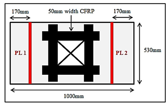
Figure 9.
Locations of two point loads.
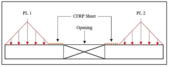
Figure 10.
Uniformly varying load.
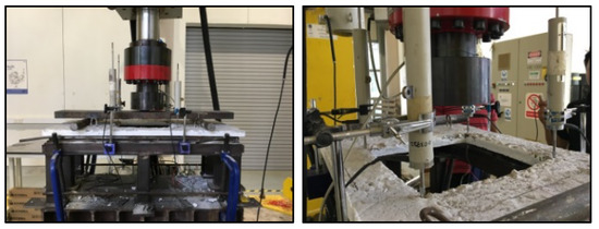
Figure 11.
Slab testing configuration.
3. Results
3.1. Load, P (kN) vs. Deflection, δ (mm)
Based on the experimental work conducted, it was observed that the curve responses for all ten slabs are almost similar. The load applied is directly proportional to the deflection occurred until it reaches a point where the slabs undergo failure. Better contact between the slab and the frame support can be seen when the load applied on the slab surface increased. At a certain point, the slab started to crack and failed when the maximum load has reached. Hence, Hooke’s Law obeys in this region. Figure 12, Figure 13, Figure 14, Figure 15, Figure 16 and Figure 17 show the results of load applied against deflection for each of the slabs.
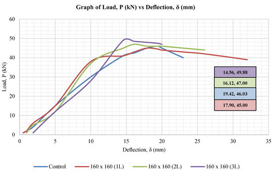
Figure 12.
Graph of load vs. deflection for 160 mm × 160 mm opening size.
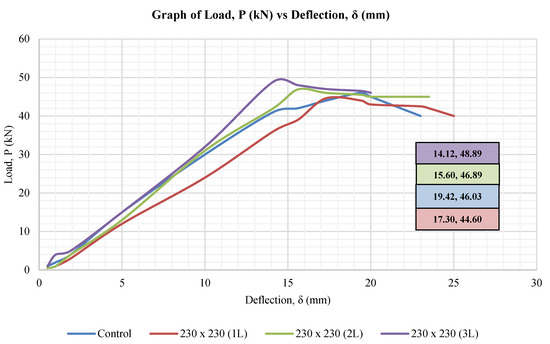
Figure 13.
Graph of load vs. deflection for 230 mm × 230 mm opening size.
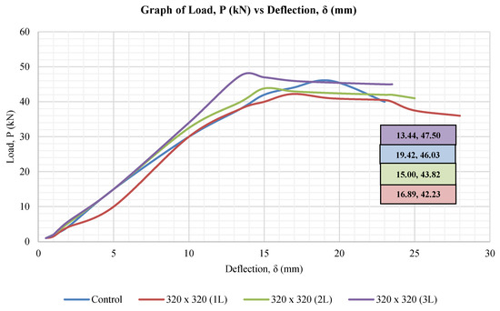
Figure 14.
Graph of load vs. deflection for 320 mm × 320 mm opening size.
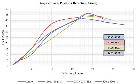
Figure 15.
Graph of load vs. deflection for 1 layer of CFRP sheet.
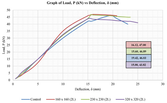
Figure 16.
Graph of load vs. deflection for 2 layers of CFRP sheet.
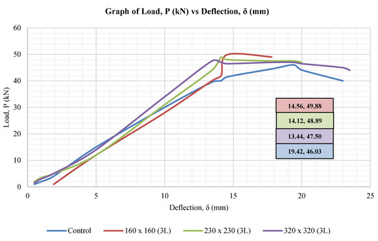
Figure 17.
Graph of load vs. deflection for 3 layers of CFRP sheet.
Based on the graphs provided below, it shows that slabs with three layers of the CFRP sheet can take a higher load as compared to the slab with only one layer of the CFRP sheet. By taking the number of layers of the CFRP sheet as a variable, the deflection is lower when the load is higher. On the other hand, by taking the size of the opening as the variable, the load is proportional to the deflection. This is due to the heavyweight of the slab with a larger surface area and smaller opening size.
3.2. Load, P (kN); Flexural Strength, R (MPa); and Deflection, δ (mm)
Table 5 represents the observed data for the flexural behavior concerning load and deflection for all ten slabs tested during the experimental work. Flexural strength (f) has been obtained using Equation (1).
where,
Table 5.
Summary of load, flexural strength and deflection of slabs tested.
- f = Flexural strength
- P = Maximum Load
- a = Distance between Supporting and Loading Pins
- b = Specimen Width
- d = Specimen Thickness
3.3. Stress Concentration Factor, k
A stress concentration factor (k) is a dimensionless factor that is used to quantify how concentrated the stress is in material, and it is defined as the ratio of the highest stress in the element to the reference stress. Reference stress is the total stress within an element under the same loading conditions without the stress concentrators, meaning the total stress on the material where the material is free from flaws such as holes, cuts, shoulders, or narrow passes. Figure 18 shows the results of the stress concentration factor for all nine slabs tested and the values have been calculated using Equations (2) to (11). Aside from that, Figure 19 shows the labeling on rosette strain gauge for the reading of εa, εb, and εc values.
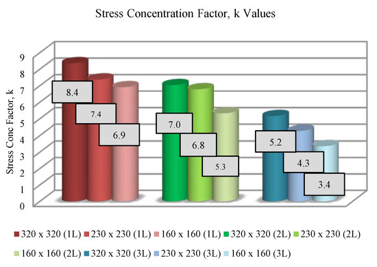
Figure 18.
Summary of stress concentration factor, k.
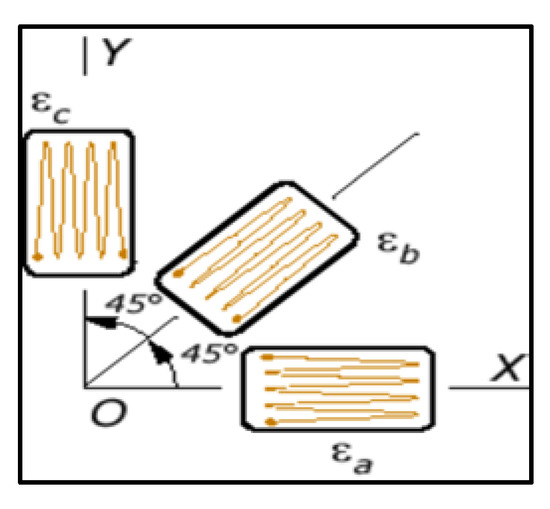
Figure 19.
Rosette strain gauge.
Calculation of stress concentration factor, k, with Equations (2) to (11).
Rosette strain gauge:
Stress estimation:
Principle stresses:
Stress concentration factor, k:
4. Discussion
4.1. General
Based on the experimental testing results, in general, all ten slabs’ responses are similar. When the load applied on the slab surface was increased, it caused a better contact between the slab and the frame support. At a certain point, the slab started to crack and failed when the maximum load was reached. Based on the results collected, the maximum load the slab can withstand is between 42 kN to 50 kN. Meanwhile, the deflection range is between 14 mm to 18 mm. For stress concentration factor, k value, all ten slabs’ values are between 3 and 9, whereas the flexural strengths are between 7 MPa and 10 MPa.
Based on the results collected, slabs with three layers of CFRP sheets can take a higher load as compared to a slab with only one layer of the CFRP sheet. Taking the number of CFRP layers as a variable, as the load gets higher, the deflection on the slab gets lower. On the other hand, taking the size of the opening as the variable, as the load gets higher, the deflection gets higher as well. This is due to the weight of the slab, which has a larger surface area but a smaller opening size. The smaller the opening size on the slab, the weight of the slab is more significant; therefore, higher deflection occurred. Besides, when the opening size is more significant, space/distance between the point loads and CFRP sheet is smaller causing the propagation of the crack to be lesser.
4.2. Cracking and Yield Lines
For each slab, it is observed that the first crack started to appear near the point loads due to the high concentration of stress at both points, as shown in Figure 20, Figure 21, Figure 22 and Figure 23. As the applied load increases, the crack propagation continued to increase. In contrast, some researchers stated that the first crack appeared diagonally near a corner due to the openings. For the control slab, it was observed that the crack propagated from two points until it reached the middle part of the slab as shown in Figure 20. This is in contrast with other research papers that stated the first crack of a homogenous slab appears in the middle of the slab. The difference is deduced due to the position and the number of point load used for this particular experimental study. Other than that, the load configuration adopted for this experiment is uniformly varying load (UVL), meaning that the load is spread over the slab in such a manner that the rate of loading varies from each point along with the slab. Therefore, the load is zero at one end and increases uniformly to the other end. This type of load is known as a triangular load. On the contrary, based on previous research studies, most researchers experimented by adopting a uniformly distributed load (UDL) during the testing.
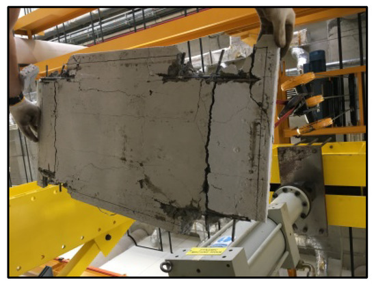
Figure 20.
Control slab.
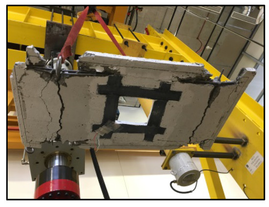
Figure 21.
160 mm × 160 mm (2 L).
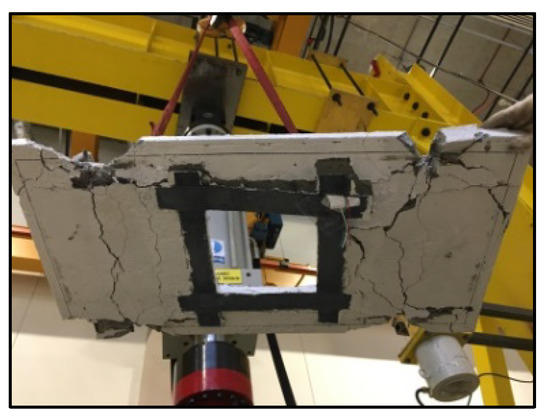
Figure 22.
230 mm × 230 mm (2 L).
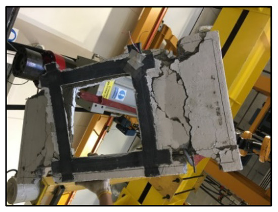
Figure 23.
320 mm × 320 mm (2 L).
Besides, the yield line pattern observed is not like any other typical two-way slab which consists of negative and positive yield lines due to negative and decisive moments. Instead, the yield lines that appeared on the slab were highly dependent on the location of the two-point loads on it. When the applied load increased, this caused the slab to experience stress concentration at the two-point loads. The cracks under the loading area indicate punching failure of the slab under the loading surface. With the presence of the CFRP sheet at the edge of the opening, the crack stopped propagating to every corner of the opening. As stated by past researchers, the crack propagation and crack size continued to increase with the increase of loading. For the CFRP strengthened slabs, the cracks were narrower and more widely spread in comparison to the cracks in the steel-reinforced slabs. This depends mainly on the existing openings, and accordingly, a decreased total available loading area gives a lower total load.
Furthermore, it is observed that cracking stopped until it reached the CFRP sheets, as shown in Figure 21, Figure 22 and Figure 23. Based on the experimental test, the worst part of the slab that failed was at the point where the two-point loads and frame support were perpendicular to each other. Referring to Figure 23, this condition can be explained in such a way that both the frame and the two-point loads exerted pressure on one another as the load increased, hence causing the slab to fail badly at that particular point. In smaller opening sizes, the cracks spread more commonly as compared to the bigger size of the opening. The reason for such a condition is because the slab with a smaller opening has a larger surface area for the crack to propagate as compared to a slab with a larger opening, which has a lesser surface area. Hence, the deflection is lesser, and therefore, the cracks appeared to be narrower. However, it can be concluded that the size of opening, the number of CFRP layers, and the location of the point loads influenced the cracking and yield lines pattern.
4.3. Load Carrying Capacity and Deflection
In general, all slabs with opening strengthened with CFRP layers show similar load-deflection behavior up to failure. However, the failure mode differs in comparison with the control slab. The control slab demonstrates a more ductile response; however, the failure mode of slabs strengthened with CFRP was a bit more brittle. Based on the data produced by the load cell, slabs that were strengthened using CFRP sheets can be increased in terms of their load-carrying capacity, but it only worked when the CFRP layer is more than or equal to two. Slabs with only one layer of the CFRP sheet have a lesser load-carrying capacity in comparison to the control slab. On the other hand, slabs with two and three layers of CFRP sheets have higher load carrying capacity in comparison to the control slab as shown in Figure 24 and Figure 25. When the number of CFRP layers increases, the load-carrying capacity also increases as shown in Figure 26 and Figure 27. This is because concrete is good in compression but poor in tension.
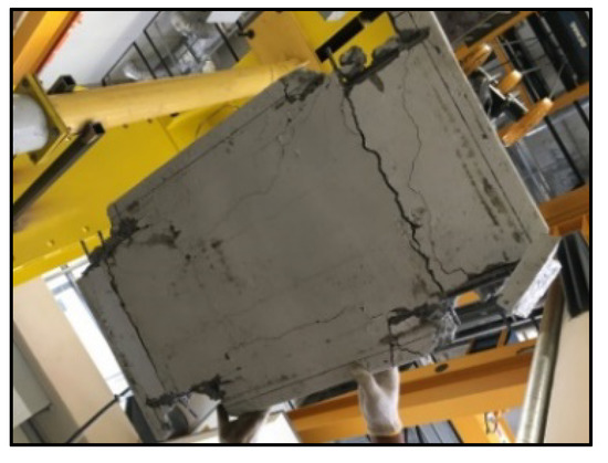
Figure 24.
Control slab.
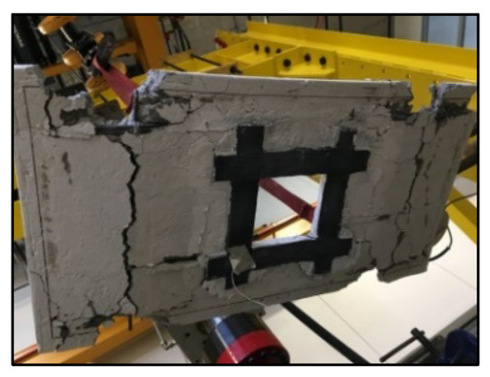
Figure 25.
160 mm × 160 mm (3 L).
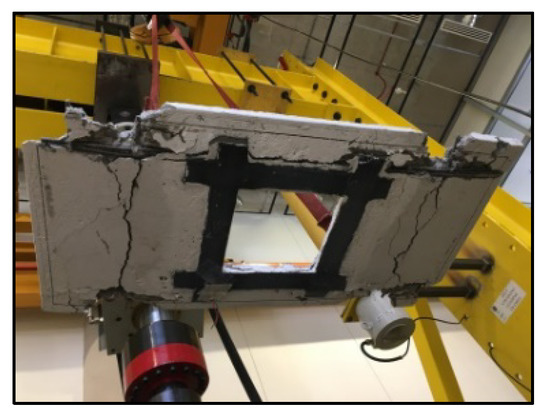
Figure 26.
230 mm × 230 mm (3 L).
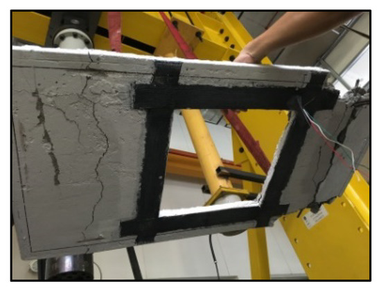
Figure 27.
320 mm × 320 mm (3 L).
Therefore, CFRP sheets need to be attached to the tension surface of the slab as it will offer ease in the uniform dissemination of tensile forces. This will result in reduced deflected and delay in crack propagation. Based on the observed result, the theory is confirmed that a higher load capacity causes a lower deflection. That is why the data shows the maximum load with minimum deflection. There is a noticeable difference in the load-carrying capacity between the CFRP strengthened small and large opening where it carried 4% to 9% higher loads. The main reason for this is most likely that the behavior of the slabs with a large opening is closer to a system of beams than a slab. Moreover, the load-carrying capability between the smaller and larger size openings strengthened with CFRP sheets is significantly different; as shown in Figure 25, Figure 26 and Figure 27. However, the size of the opening, CFRP layers number, and location of point loads influenced the load-carrying capacity.
4.4. CFRP and Failure Characteristics
Based on Figure 28, Figure 29 and Figure 30, the CFRP sheet is still in good condition even though the slab has already failed. The CFRP sheet has not teared up or even broken. This shows that the concrete has failed in flexural, not the CFRP sheet. In summary, the CFRP sheet is able to carry the tensile forces, delay the crack propagation, and enable the slab to experience a higher load-carrying capacity. It is evident that the CFRP materials contributed to an increased load-carrying capacity until the bond between CFRP material and concrete failed as shown in Figure 29 and Figure 30. Based on past research studies, normally the rule of thumb states that the bond development length for CFRP reinforcement needs not to be greater than 0.2 m. De-bonding cracks appeared at the late stage of loading that resulted in a separation or detachment of the CFRP material as shown in Figure 29. These cracks were located along the edges of the strengthening material. This shows that the end anchor section is to some degree preventing a premature bond failure at the cutting end of CFRP. After the appearance of these cracks, the slab failed due to accelerated concrete flexural phenomenon, and the CFRP layer de-bonded from the slabs without any rupture present at the CFRP.
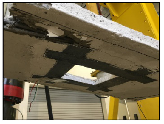
Figure 28.
160 mm × 160 mm (1 L).
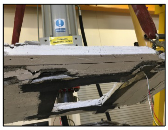
Figure 29.
230 mm × 230 mm (1 L).
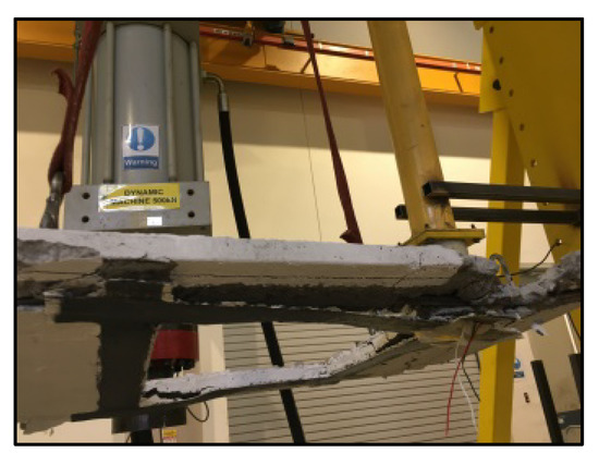
Figure 30.
320 mm × 320 mm (1 L).
5. Conclusions
The scope of the research work presented in this paper is limited to two-way RC slabs with a fixed support at four ends and subjected to two-point loads with a uniformly varying load distribution. There are ten slabs in total; nine slabs with opening and another slab acting as a control slab. CFRP sheets are used for the strengthening of slabs with opening, and epoxy glue is the bonding mechanism between the slab and CFRP sheet. Furthermore, the size of the opening is numerical; 5%, 10%, and 20% of the total area of the slab. On the other hand, the number of CFRP layers is varied in this way: one layer, two layers, and three layers of CFRP sheet. The aims of this research are to evaluate how the openings influence the structural behavior of the RC slabs and how the number of CFRP sheet layers affect the structural behavior of RC slabs with various sizes of opening. The structural behavior of each slab with and without opening was investigated at the end of this research.
It can be concluded that slabs with three layers of the CFRP sheet can take a higher load as compared to the slab with only one layer of the CFRP sheet. Taking the number of layers of the CFRP sheet as a variable, as the load gets higher, the deflection occurring on the slab gets lower. On the other hand, taking the size of the opening as the variable, as the load gets higher, the deflection gets higher as well. This is due to the weight of the slab with a larger surface area and a smaller opening size. When the opening size on the slab is smaller, the weight of the slab is greater, therefore higher deflection tends to occur. Besides, when the opening size on the slab is larger, the distance between the point loads and the CFRP sheet is smaller causing the propagation of crack to be lesser. On top of that, the effective number of layers of CFRP sheet is three because it has the highest ultimate load-carrying capacity as compared to others, hence the deflection is at the lowest.
Based on the experimental program conducted, it was observed that with the increment for each layer, the percentage of load carrying capacity for each slab is within 4% to 9%. On the other hand, the load-carrying capacity decreases as the opening size increases. Load carrying capacity decreases up to 7% when the size of opening increases to its maximum (as considered during the experimental study). Equally important, when the size of the opening is greater, the value of the stress concentration factor will be lesser or lower. This shows that a larger opening tends to experience more stress as compared to the smaller opening. The higher the number of CFRP layers, the lower the value of the stress concentration factor. This shows that the number of CFRP layers will cause the slabs to have a higher load-carrying capacity. As a result, it is confirmed that CFRP sheets can be used to maintain and even increase the original load carrying capacity of slabs with openings.
Author Contributions
Conceptualization, B.S.M., and M.A.W.; methodology, S.S.A., and A.A.; investigation, S.S.A., and A.A.; writing—original draft preparation, S.S.A., and A.A.; writing—review and editing, S.S.A. and A.A.; supervision, B.S.M. and M.A.W. All authors have read and agreed to the published version of the manuscript.
Funding
This research received no external funding.
Acknowledgments
The authors would like to acknowledge Universiti Teknologi PETRONAS (UTP), Malaysia, to facilitate this research study.
Conflicts of Interest
The authors declare no conflict of interest.
References
- Mansur, M.A.; Huang, L.M.; Tan, K.H.; Lee, S.L. Deflections of reinforced concrete beams with web openings. ACI Struct. J. 1992, 89, 391–397. [Google Scholar]
- Anwar, A.; Mohammed, B.S.; Liew, M.S.; Wahab, M.A. Below-Grade Sulfur Storage Pits in Oil Refineries: A Review. J. Fail. Anal. Prev. 2019, 1–16. [Google Scholar] [CrossRef]
- Benitez, M.A.; Darwin, D.; Donahey, R.C. Deflections of composite beams with web openings. J. Struct. Eng. 1998, 124, 1139–1147. [Google Scholar] [CrossRef][Green Version]
- Batti, M.; Silva, B.; Piccinini, Â.; Godinho, D.; Antunes, E.G.P. Experimental Analysis of the Strengthening of Reinforced Concrete Beams in Shear Using Steel Plates. Infrastructures 2018, 3, 52. [Google Scholar] [CrossRef]
- Mansur, M.A.; Tan, K.-H. Concrete Beams with Openings: Analysis and Design; CRC Press LLC: Boca Raton, FL, USA, 1999. [Google Scholar]
- Mohammed, B.; Bakar, B.H.; Choong, K. The Effects of Opening on the Structural Behavior of Masonry Wall Subjected to Compressive Loading—Strain Variation. Open Civ. Eng. J. 2009, 3, 62–73. [Google Scholar] [CrossRef]
- Cheng, H.T.; Mohammed, B.S.; Mustapha, K.N. Experimental and analytical analysis of pretensioned inverted T-beam with circular web openings. Int. J. Mech. Mater. Des. 2009, 5, 203–215. [Google Scholar] [CrossRef]
- Chin, S.C.; Yahaya, F.M.; Ing, D.O.H.S.; Kusbiantoro, A.; Chong, W.K. Experimental Study on Shear Strengthening of RC Deep Beams with Large Openings Using CFRP. In Proceedings of the International Conference on Architecture, Structure and Civil Engineering (ICASCE’15), Antalya, Turkey, 7–8 September 2015; pp. 89–95. [Google Scholar]
- Mohammed, B.S.; Ean, L.W.; Malek, M.A. One way RC wall panels with openings strengthened with CFRP. Constr. Build. Mater. 2013, 40, 575–583. [Google Scholar] [CrossRef]
- Chin, S.C.; Shafiq, N.; Nuruddin, M.F. Strengthening of RC Beams Containing Large Opening at Flexure with CFRP laminates. Int. J. Civ. Environ. Eng. 2011, 5, 743–749. [Google Scholar]
- El Maaddawy, T.; Sherif, S. FRP composites for shear strengthening of reinforced concrete deep beams with openings. Compos. Struct. 2009, 89, 60–69. [Google Scholar] [CrossRef]
- Mohammed, B.S.; Alanni, O. Shear Capacity of RC Beams with Web Openings Strengthened with Multi Layers of CFRP. Appl. Mech. Mater. 2014, 567, 494–498. [Google Scholar] [CrossRef]
- Mohammed, B.S.; Ean, L.W.; Hossain, K.M.A. CFRP Composites for Strengthening of Reinforced Concrete Walls with Openings. Int. J. Eng. Res. Appl. 2010, 1, 1841–1852. [Google Scholar]
- Li, X.; Xie, H.; Yan, M.; Gou, H.; Zhao, G.; Bao, Y. Eccentric Compressive Behavior of Reinforced Concrete Columns Strengthened Using Steel Mesh Reinforced Resin Concrete. Appl. Sci. 2018, 8, 1827. [Google Scholar] [CrossRef]
- Anwar, A. The Influence of Waste Glass Powder as a Pozzolanic Material in Concrete. Int. J. Civ. Eng. Technol. 2016, 7, 131–148. [Google Scholar]
- Anwar, A.; Mohammed, B.S.; Liew, M.S.; Wahab, A. Enhanced Properties of Cementitious Composite Tailored with Graphene Oxide Nanomaterial—A Review. Dev. Built Environ. 2019. [Google Scholar] [CrossRef]
- Chin, S.C.; Shafiq, N.; Nuruddin, M.F. FRP as strengthening material for Reinforced Concrete beams with openings—A review. KSCE J. Civ. Eng. 2015, 19, 213–219. [Google Scholar] [CrossRef]
- Gudonis, E.; Timinskas, E.; Gribniak, V.; Kaklauskas, G.; Arnautov, A.K.; Tamulėnas, V. FRP Reinforcement for Concrete Structures: State-of-the-Art Review of Application and Design. Eng. Struct. Technol. 2014, 5, 147–158. [Google Scholar] [CrossRef]
- Triantafillou, T. Shear Strengthening of Reinforced Concrete Beams Using Epoxy-Bonded FRP Composites. ACI Struct. J. 1998, 95, 107–115. [Google Scholar]
- Tian, C.H.; Mohammed, B.S.; Mustapha, K.N. Interaction Diagram in Finite Element Analysis of Deflection of Pretensioned Inverted T-Beam with Web Openings Strengthened with GFRP Laminates. In Proceedings of the 2009 Second International Conference on Information and Computing Science, Manchester, UK, 21–22 May 2009; Volume 1, pp. 335–338. [Google Scholar]
- Cheng, H.T.; Mohammed, B.S.; Mustapha, K.N. Finite element analysis and structural design of pretensioned inverted T-beams with web openings. Front. Archit. Civ. Eng. China 2009, 3, 148–157. [Google Scholar] [CrossRef]
- Tariq, M. Shear Behaviour of RC Deep Beams with openings strengthened with Carbon Fiber Reinforced Polymer. Int. J. Civ. Environ. Eng. 2017, 11, 1138–1143. [Google Scholar]
- Al-sheikh, S.A. Flexural Behavior of RC Beams With Opening. Concr. Res. Lett. 2014, 5, 812–824. [Google Scholar]
- Zhang, Z.; Hsu, C.-T.T. Shear Strengthening of Reinforced Concrete Beams Using Carbon-Fiber-Reinforced Polymer Laminates. J. Compos. Constr. 2005, 9, 158–169. [Google Scholar] [CrossRef]
- Khalifa, A.; Gold, W.J.; Nanni, A. Contribution of Externally Bonded FRP to Shear Capacity of RC Flexural Members. J. Compos. Constr. 1998, 2, 195–202. [Google Scholar] [CrossRef]
- Anwar, A.; Sabih, A.; Husain, S.M.A.; Ahmad, S.A. Salvage of Ceramic Waste and Marble Dust for the Refinement of Sustainable Concrete. Int. J. Civ. Eng. Technol. 2015, 6, 79–92. [Google Scholar]
- Al-Ahmed, A.H.A.; Al-Jburi, M.H.M. Behavior of Reinforced Concrete Deep Beams Strengthened with Carbon Fiber Reinforced Polymer Strips. J. Eng. 2016, 8, 37–53. [Google Scholar]
- Harajli, M.; Soudki, K. Shear Strengthening of Interior Slab–Column Connections Using Carbon Fiber-Reinforced Polymer Sheets. J. Compos. Constr. 2003, 7, 145–153. [Google Scholar] [CrossRef]
- Chen, Z.B.; Huang, P.Y.; Li, Z.W.; Guo, X.Y.; Zhao, C.; Zheng, X.H.; Yang, Y. Fatigue Performance of RC Beams Strengthened with CFRP under Overloads with a Ladder Spectrum. Sensors 2018, 18, 3321. [Google Scholar] [CrossRef]
- Saleh, H.; Abdouka, K.; Al-Mahaidi, R.; Kalfat, R. Strengthening of slab–column connections against punching shear using FRP materials: State-of-the-art review. Aust. J. Struct. Eng. 2018, 19, 188–203. [Google Scholar] [CrossRef]
- Soudki, K.; El-sayed, A.K.; Vanzwol, T. Strengthening of concrete slab-column connections using CFRP strips. J. King Saud Univ. Eng. Sci. 2012, 24, 25–33. [Google Scholar] [CrossRef]
- Park, H.; Park, J.-S.; Kang, J.-Y.; Jung, W.-T. Fatigue Behavior of Concrete Beam with Prestressed Near-Surface Mounted CFRP Reinforcement According to the Strength and Developed Length. Materials 2018, 12, 51. [Google Scholar] [CrossRef]
- Silva, M.A.L.; Gamage, J.C.P.H.; Fawzia, S. Performance of slab-column connections of flat slabs strengthened with carbon fiber reinforced polymers. Case Stud. Constr. Mater. 2019, 11, e00275. [Google Scholar] [CrossRef]
- Anil, Ö.; Kaya, N.; Arslan, O. Strengthening of one way RC slab with opening using CFRP strips. Constr. Build. Mater. 2013, 48, 883–893. [Google Scholar] [CrossRef]
- Salman, W.D. Strengthening of Reinforced Concrete One-Way Slabs with Opening using CFRP Strip in Flexural. Int. J. Sci. Res. 2015, 4, 4–438. [Google Scholar]
- Sobuz, H.; Ahmed, E.; Hasan, N.; Uddin, M.A. Use of carbon fiber laminates for strengthening reinforced concrete beams. Int. J. Civ. Struct. Eng. 2012, 2, 67. [Google Scholar]
- Teng, J.G.; Smith, S.; Yao, J.; Chen, J.-F. Intermediate Crack Induced Debonding in RC Beams and Slabs. Constr. Build. Mater. 2003, 17, 447–462. [Google Scholar] [CrossRef]
- Limam, O.; Nguyen, V.; Foret, G. Numerical and experimental analysis of two-way slabs strengthened with CFRP strips. Eng. Struct. 2005, 27, 841–845. [Google Scholar] [CrossRef]
- Kim, Y.; Longworth, J.; Wight, G.; Green, M. Punching Shear of Two-way Slabs Retrofitted with Prestressed or Non-prestressed CFRP Sheets. J. Reinf. Plast. Compos. 2010, 29, 1206–1223. [Google Scholar] [CrossRef]
- Michel, L.; Ferrier, E.; David, B.; Agbossou, A. Criteria for punching failure mode in RC slabs reinforced by externally bonded CFRP. Compos. Struct. 2007, 81, 438–449. [Google Scholar] [CrossRef]
- Ahmad, S.; Anwar, A.; Mohammed, B.S.; Wahab, M.b.A.; Ahmad, S.A. Strength Behavior of Concrete by Partial Replacement of Fine Aggregate with Ceramic Powder. Int. J. Recent Technol. Eng. 2019, 8, 5712–5718. [Google Scholar]
- Foret, G.; Limam, O. Experimental and numerical analysis of RC two-way slabs strengthened with NSM CFRP rods. Constr. Build. Mater. 2008, 22, 2025–2030. [Google Scholar] [CrossRef]


© 2020 by the authors. Licensee MDPI, Basel, Switzerland. This article is an open access article distributed under the terms and conditions of the Creative Commons Attribution (CC BY) license (http://creativecommons.org/licenses/by/4.0/).