Heat Treatment of Basalt Fiber Reinforced Expanded Clay Concrete with Increased Strength for Cast-In-Situ Construction

 ,
,  ,
,  ,
,  ,
,  , ,
, ,  and
and
Abstract

1. Introduction
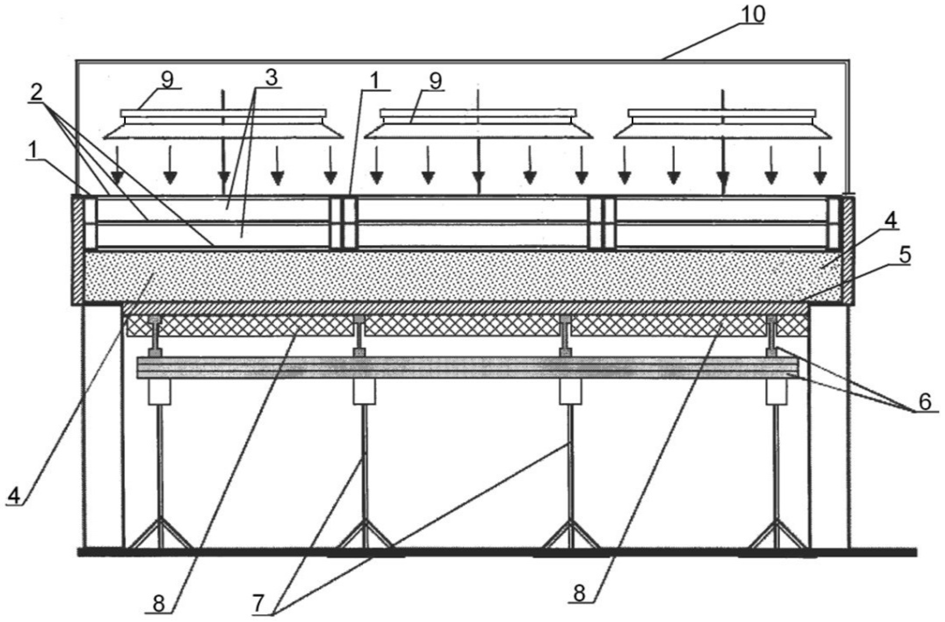
2. Technology of Heat Treatment
3. Materials and Methods
3.1. Materials
- -
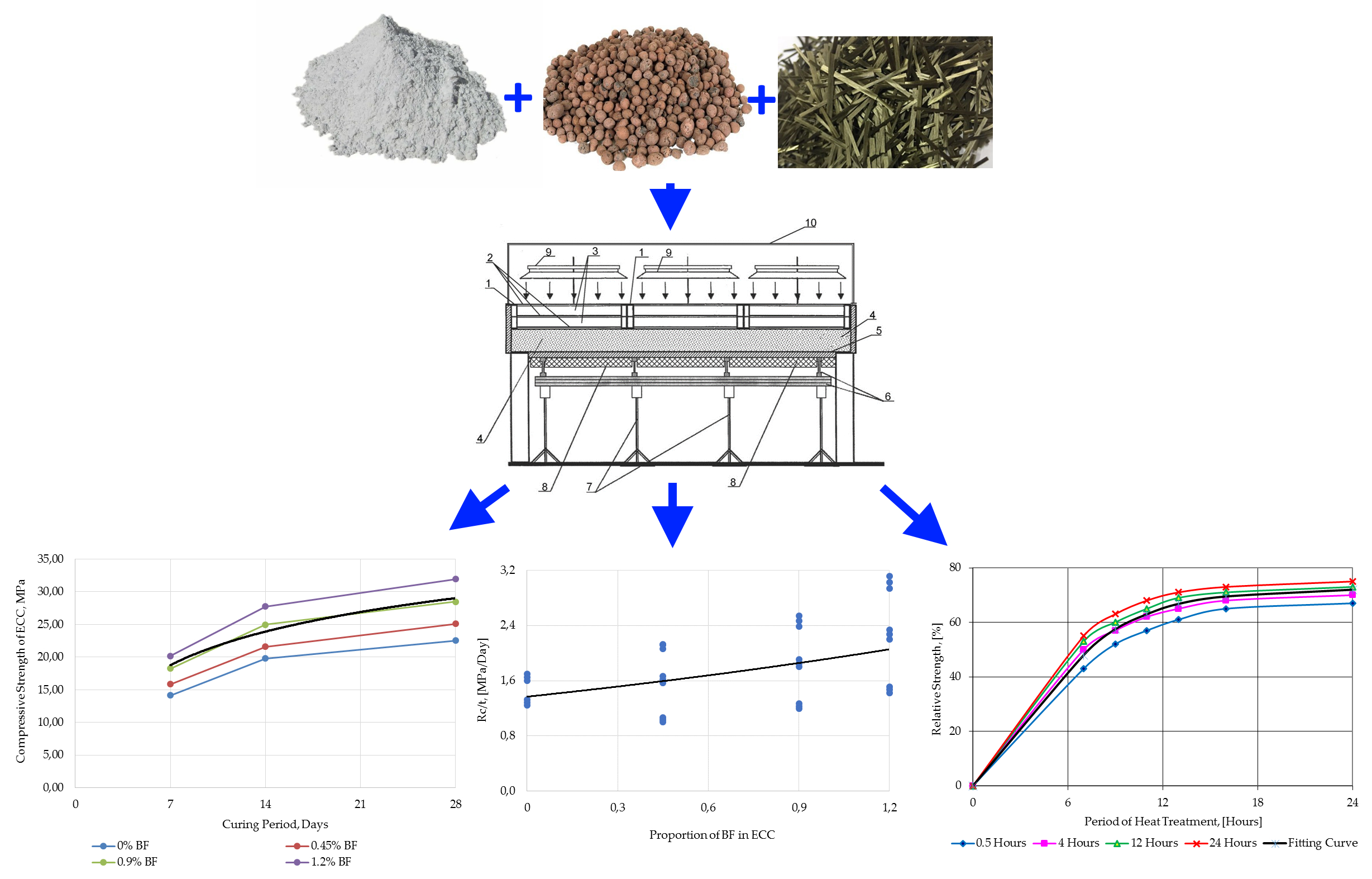
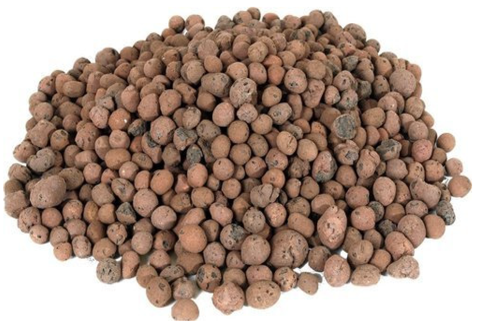
- Lightweight Expanded Clay Aggregate (LECA) with fractions of 5–10 mm = 200 kg/m3 was used as the coarse aggregate;
- -
- Silica sand with a fineness modulus of 2.7 = 585 kg/m3 was used as the fine aggregate;
- -
- Silica powder of 50 µm = 100 kg/m3 was used as a mineral filler;
- -
- Portland cement CEM I 42.5 N = 500 kg/m3 was used as a binder;
- -
- Microsilica = 62.5 kg/m3 and fly ash = 62.5 kg/m3 were used as the mineral additives;
- -
- SikaPlast®Concrete in liquid form = 8 L/m3 was used as a superplasticizing admixture;
- -
- Tap water = 255 L/m3 was used for mixing.
3.2. Specimen Making and Research Method
4. Results and Discussion
5. Conclusions
Author Contributions
Funding
Conflicts of Interest
References
- Real, S.; Gomes, M.G.; Rodrigues, A.M.; Bogas, J.A. Contribution of structural lightweight aggregate concrete to the reduction of thermal bridging effect in buildings. Constr. Build. Mater. 2016, 121, 460–470. [Google Scholar] [CrossRef]
- Vijayalakshmi, R.; Ramanagopal, S. Structural concrete using expanded clay aggregate: A review. Indian J. Sci. Technol. 2018, 11, 1–12. [Google Scholar] [CrossRef]
- Klyuev, S.V.; Khezhev, T.A.; Pukharenko, Y.V.; Klyuev, A.V. To the question of fiber reinforcement of concrete. Mater. Sci. Forum 2018, 945, 25–29. [Google Scholar] [CrossRef]
- Fediuk, R.S.; Lesovik, V.S.; Svintsov, A.P.; Mochalov, A.V.; Kulichkov, S.; Stoyushko, N.Y.; Gladkova, N.A.; Timokhin, R.A. Self-compacting concrete using pretreatmented rice husk ash. Mag. Civ. Eng. 2018, 79, 66–76. [Google Scholar]
- Cherevatova, A.V.; Zhernovskaya, I.V.; Alehin, D.A.; Kozhukhova, M.I.; Kozhukhova, N.I.; Yakovlev, E.A. Theoretical aspects of development of composite nanostructured gypsum binder characterized by increased heat resistance. Constr. Mater. Prod. 2019, 2, 5–13. [Google Scholar]
- Strokova, V.V.; Babaev, V.B.; Markov, A.Y.; Sobolev, K.G.; Nelyubova, V.V. Comparative evaluation of road pavement structures using cement concrete. Constr. Mater. Prod. 2019, 2, 56–63. [Google Scholar]
- Abirami, T.; Loganaganandan, M.; Murali, G.; Fediuk, R.; Sreekrishna, R.V.; Vignesh, T.; Januppriya, G.; Karthikeyan, K. Experimental research on impact response of novel steel fibrous concretes under falling mass impact. Constr. Build. Mater. 2019, 222, 447–457. [Google Scholar] [CrossRef]
- Klyuev, S.V.; Khezhev, T.A.; Pukharenko, Y.V.; Klyuev, A.V. Experimental study of fiber-reinforced concrete structures. Mater. Sci. Forum 2018, 945, 115–119. [Google Scholar] [CrossRef]
- Fediuk, R.; Smoliakov, A.; Muraviov, A. Mechanical properties of fiber-reinforced concrete using composite binders. Adv. Mater. Sci. Eng. 2017, 2017, 2316347. [Google Scholar] [CrossRef]
- Akhtyamova, L.S.; Sabitov, L.S.; Mailyan, A.L.; Mailyan, L.R.; Radaykin, O.V. Technological and design features of designing a modular reinforced concrete foundation for a high-rise building of various types. Constr. Mater. Prod. 2019, 2, 5–11. [Google Scholar]
- Manzhilevskaya, S.E. Organizational and economic problems of ecological safety in construction. Constr. Mater. Prod. 2019, 2, 73–78. [Google Scholar]
- Sun, X.; Gao, Z.; Cao, P.; Zhou, C. Mechanical properties tests and multiscale numerical simulations for basalt fiber reinforced concrete. Constr. Build. Mater. 2019, 202, 58–72. [Google Scholar] [CrossRef]
- Fediuk, R. Reducing permeability of fiber concrete using composite binders. Spec. Top. Rev. Porous Media 2018, 9, 79–89. [Google Scholar] [CrossRef]
- Klyuev, S.V.; Klyuev, A.V.; Khezhev, T.A.; Pukharenko, Y.V. Technogenic sands as effective filler for fine-grained fibre concrete. J. Phys. Conf. Ser. 2018, 1118, 012020. [Google Scholar] [CrossRef]
- Karagol, F.; Demirboga, R.; Kaygusuz, M.A.; Yadollahi, M.M.; Polat, R. The influence of calcium nitrate as antifreeze admixture on the compressive strength of concrete exposed to low temperatures. Cold Reg. Sci. Technol. 2013, 89, 30–35. [Google Scholar] [CrossRef]
- Klyuev, S.V.; Klyuev, A.V.; Shorstova, E.S. The micro silicon additive effects on the fine-grassed concrete properties for 3-d additive technologies. Mater. Sci. Forum 2019, 974, 131–135. [Google Scholar] [CrossRef]
- Fediuk, R.; Pak, A.; Kuzmin, D. Fine-Grained Concrete of Composite Binder. IOP Conf. Ser. Mater. Sci. Eng. 2017, 262, 012025. [Google Scholar] [CrossRef]
- Polat, R. The effect of antifreeze additives on fresh concrete subjected to freezing and thawing cycles. Cold Reg. Sci. Technol. 2016, 127, 10–17. [Google Scholar] [CrossRef]
- Dudin, M.O.; Vatin, N.I.; Barabanshchikov, Y.G. Modeling a set of concrete strength in the program ELCUT at warming of monolithic structures by wire. Mag. Civ. Eng. 2015, 54, 33–45. [Google Scholar] [CrossRef]
- Nikolenko, Y.V.; Manaeva, M.M.; Stashevskaya, N.A. About the technology of concreting in cast-in-situ building construction. RUDN J. Eng. Res. 2014, 4, 84–89. Available online: https://elibrary.ru/item.asp?id=22697370 (accessed on 29 October 2020).
- Svintsov, A.P.; Nikolenko, Y.V.; Patrakhaltsev, N.N.; Ivanov, V.N. Improving the technology of concreting work in the cast-in-situ building construction. Constr. Mater. 2012, 1, 28–31. Available online: https://elibrary.ru/item.asp?id=17337048 (accessed on 29 October 2020).
- Fediuk, R.; Smoliakov, A.; Stoyushko, N. Increase in composite binder activity. IOP Conf. Ser. Mater. Sci. Eng. 2016, 156, 012042. [Google Scholar] [CrossRef]
- Im, D.; Sancharoen, P.; Julnipitawong, P.; Tangtermsirikul, S. Effect of chloride and corrosion of reinforcing steel on thermal behavior of concrete and its modeling. Eng. J. 2018, 22, 143–163. [Google Scholar] [CrossRef]
- Solovyanchik, A.R.; Shifrin, S.A.; Rudenko, A.E. Method for Concreting the Monolithic Structures with Elements of Different Massivity. Patent of the Russian Federation No. RU2143047C1, 1999. Available online: https://yandex.ru/patents/doc/RU2143047C1_19991220 (accessed on 29 October 2020).
- Svintsov, A.P.; Svintsova, N.K.; Nikolenko, Y.V.; Gladchenko, L.K. The Device for Thermal Treatment of Concrete in Cast-In-Situ Structures. Patent of the Russian Federation No. RU113287U1, 2012. Available online: https://yandex.ru/patents/doc/RU113287U1_20120210 (accessed on 29 October 2020).
- Fediuk, R.S.; Smoliakov, A.K.; Timokhin, R.A.; Batarshin, V.O.; Yevdokimova, Y.G. Using thermal power plants waste for building materials. IOP Conf. Ser. Earth Environ. Sci. 2018, 87, 092010. [Google Scholar] [CrossRef]
- Yew, M.K.; Mahmud, H.; Ang, B.C.; Yew, M.C. Effects of heat treatment on oil palm shell coarse aggregates for high strength lightweight concrete. Mater. Des. 2014, 54, 702–707. [Google Scholar] [CrossRef]
- Bumanis, G.; Toropovs, N.; Dembovska, L.; Bajare, D.; Korjakins, A. The effect of heat treatment on the properties of ultra high strength concrete. In Proceedings of the 10th International Scientific and Practical Conference, Rezekne, Latvia, 18–20 June 2015; pp. 22–27. [Google Scholar]
- Pillai, C.S.; Santhakumar, A.R.; Chandrasekaran, S.; Viswanathan, S.; Mathiyarasu, R.; Kumar, J.A.; Preetha, R.; Venkatraman, B. Effect of heat treatment on neutron attenuation characteristics of high density concretes (HDC). Prog. Nucl. Energy 2016, 93, 76–83. [Google Scholar]
- Derabla, R.; Benmalek, M.L. Characterization of heat-treated self-compacting concrete containing mineral admixtures at early age and in the long term. Constr. Build. Mater. 2014, 66, 787–794. [Google Scholar] [CrossRef]
- Höhlig, B.; Schröfl, C.; Hempel, S.; Noack, I.; Mechtcherine, V.; Schmidt, D.; Trommler, U.; Roland, U. Heat treatment of fresh concrete by radio waves—Avoiding delayed ettringite formation. Constr. Build. Mater. 2017, 143, 580–588. [Google Scholar] [CrossRef]
- Shui, Z.; Xuan, D.; Wan, H.; Cao, B. Rehydration reactivity of recycled mortar from concrete waste experienced to thermal treatment. Constr. Build. Mater. 2008, 22, 1723–1729. [Google Scholar] [CrossRef]
- Pandurangan, K.; Dayanithy, A.; Prakash, S.O. Influence of treatment methods on the bond strength of recycled aggregate concrete. Constr. Build. Mater. 2016, 120, 212–221. [Google Scholar] [CrossRef]
- Kharun, M.; Nikolenko, Y.V.; Stashevskaya, N.A.; Koroteev, D.D. Thermal treatment of self-compacting concrete in cast-in-situ construction. Key Eng. Mater. 2017, 753, 315–320. [Google Scholar] [CrossRef]
- GOST 10180-2012. Concretes: Methods for Strength Determination Using Reference Specimens; Standartinform: Moscow, Russia, 2013; Available online: http://gostexpert.ru/gost/gost-10180-2012 (accessed on 29 October 2020).
- Gmurman, V.E. Theory of Probability and Mathematical Statistics, 9th ed.; Vysshaya Shkola: Moscow, Russia, 2009; Available online: http://lib.maupfib.kg/wp-content/uploads/2015/12/Teoria_veroatnosty_mat_stat.pdf (accessed on 29 October 2020).
- Gmurman, V.E. A Guide to Solving Problems in Probability Theory and Mathematical Statistics, 10th ed.; Vysshaya Shkola: Moscow, Russia, 2004; Available online: http://orlovsky-mephi.ru/books/Probability/GmurmanSolutions2004.pdf (accessed on 29 October 2020).


| Physical Property | Value |
|---|---|
| Specific gravity | 0.69 |
| Fineness modulus | 5.93 |
| Bulk density (compacted), [kg/m3] | 278 |
| Water absorption (24 h), [%] | 26.4 |
| Sieve Analysis, [mm] | Cumulative Percent by Weight Passing |
| 10.0 | 90.4 |
| 8.0 | 5.7 |
| 5.0 | 3.9 |
| 3.0 | 0 |
| Physical Property | Value |
|---|---|
| Grain size, [mm] | 0.5–1.0 |
| Bulk density (compacted), [kg/m3] | 1430 |
| Hardness (on the Mohs scale) | 7 |
| Crushability | 0.3 |
| Humidity, [%] | 1.7 |
| Chemical Oxides, % | SiO2 | Al2O3 | Fe2O3 | K2O | CaO | MgO | SO3 | P2O5 | TiO | MnO | Na2O |
|---|---|---|---|---|---|---|---|---|---|---|---|
| Silica powder | 99.63 | 0.23 | 0.12 | - | 0.02 | - | - | - | - | - | - |
| Portland cement | 21.90 | 4.86 | 3.3 | 0.56 | 65.77 | 1.15 | 2.1 | - | - | - | 0.36 |
| Microsilica | 98.77 | 0.23 | 0.07 | 0.26 | 0.31 | 0.04 | 0.17 | - | - | - | 0.15 |
| Fly Ash | 66.24 | 19.81 | 6.41 | 1.39 | 3.13 | 1.21 | - | 0.36 | 0.86 | 0.05 | 0.54 |
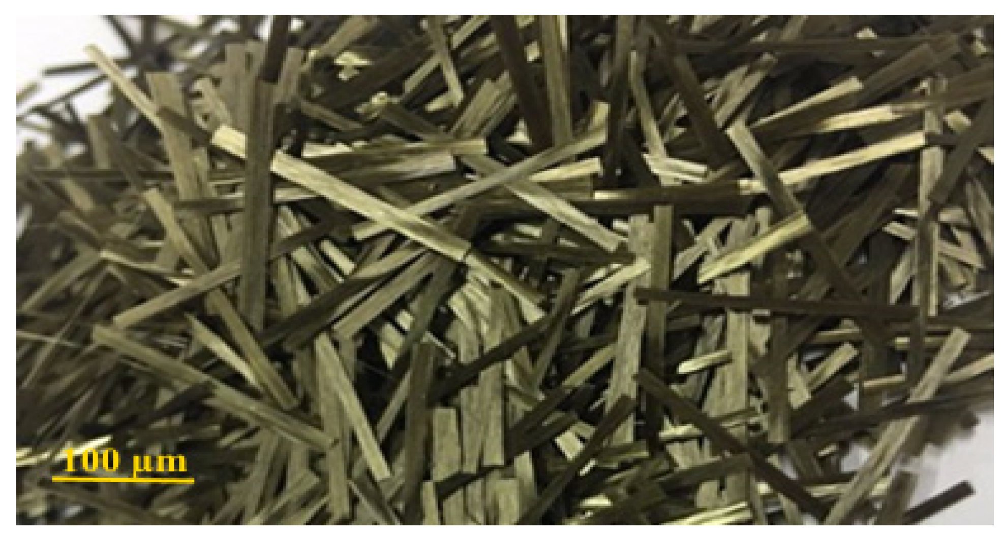
| Chemical Oxides | SiO2 | Al2O3 | FeO + Fe2O3 | Na2O + K2O | CaO | MgO | TiO2 | Others |
|---|---|---|---|---|---|---|---|---|
| Percentage (%) | 57.3 | 15.4 | 11.7 | 1.9 | 7.3 | 4.1 | 1.6 | 0.7 |
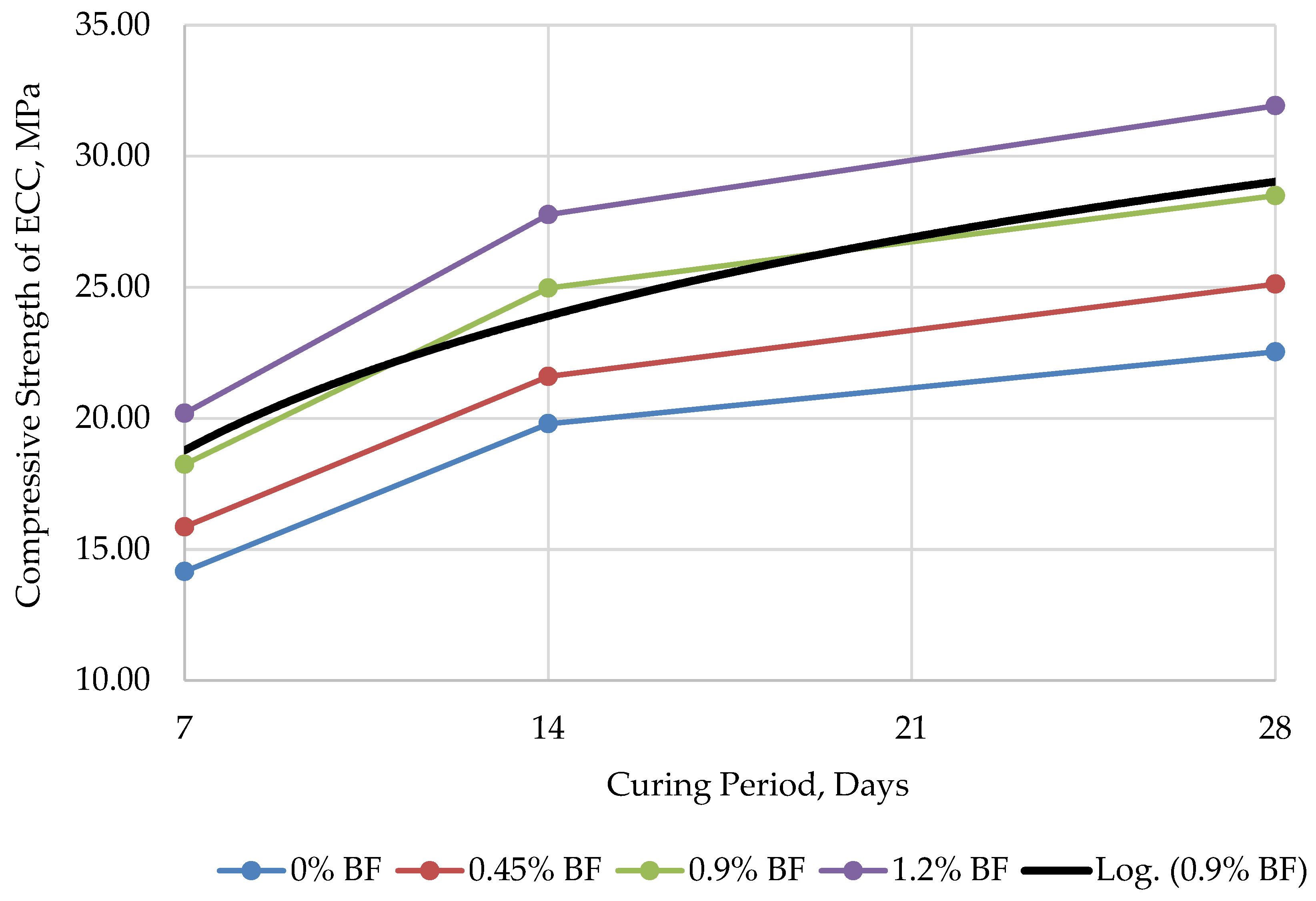
| Curing Period, [Days] | Average Compressive Strength, Rc [MPa] with Standard Deviation of Test Data | |||
|---|---|---|---|---|
| 0% BF | 0.45% BF | 0.9% BF | 1.2% BF | |
| 7 | 14.16 (0.62) | 15.86 (0.53) | 18.25 (0.72) | 20.19 (0.61) |
| 14 | 19.79 (0.54) | 21.59 (0.66) | 24.97 (0.63) | 27.77 (0.71) |
| 28 | 22.53 (0.69) | 25.12 (0.57) | 28.50 (0.68) | 31.92 (0.59) |
| Period of HT, [Hours] | Average Compressive Strength depending on Cooling Period, RHT [MPa] with Standard Deviation of Test Data | |||
|---|---|---|---|---|
| 0.5 h | 4 h | 12 h | 24 h | |
| Heat-Treated ECC Specimens with 0% BF | ||||
| 7 | 09.69 (0.71) | 11.27 (0.68) | 11.94 (0.49) | 12.39 (0.72) |
| 9 | 11.72 (0.67) | 12.84 (0.73) | 13.52 (0.66) | 14.20 (0.54) |
| 11 | 12.83 (0.65) | 13.97 (0.61) | 14.65 (0.67) | 15.32 (0.59) |
| 13 | 13.75 (0.59) | 14.64 (0.58) | 15.55 (0.57) | 16.00 (0.68) |
| 16 | 14.65 (0.69) | 15.32 (0.69) | 15.94 (0.70) | 16.45 (0.58) |
| 24 | 15.10 (0.74) | 15.77 (0.68) | 16.42 (0.64) | 16.90 (0.55) |
| Heat-Treated ECC Specimens with 0.45% BF | ||||
| 7 | 10.80 (0.61) | 12.56 (0.70) | 13.31 (0.67) | 13.82 (0.54) |
| 9 | 13.06 (0.49) | 14.32 (0.58) | 15.07 (0.58) | 15.83 (0.69) |
| 11 | 14.31 (0.66) | 15.58 (0.54) | 16.32 (0.59) | 17.08 (0.65) |
| 13 | 15.32 (0.53) | 16.33 (0.69) | 17.33 (0.70) | 17.84 (0.68) |
| 16 | 16.32 (0.57) | 17.07 (0.71) | 17.83 (0.58) | 18.34 (0.72) |
| 24 | 16.83 (0.68) | 17.58 (0.56) | 18.33 (0.68) | 18.84 (0.59) |
| Heat-Treated ECC Specimens with 0.9% BF | ||||
| 7 | 12.25 (0.58) | 14.25 (0.72) | 15.10 (0.71) | 15.67 (0.69) |
| 9 | 14.82 (0.70) | 16.24 (0.53) | 17.09 (0.67) | 17.95 (0.61) |
| 11 | 16.22 (0.71) | 17.69 (0.57) | 18.52 (0.65) | 19.38 (0.70) |
| 13 | 17.38 (0.63) | 18.50 (0.68) | 19.66 (0.69) | 20.23 (0.52) |
| 16 | 18.52 (0.57) | 19.37 (0.49) | 20.19 (0.70) | 20.80 (0.63) |
| 24 | 19.09 (0.70) | 19.94 (0.59) | 20.77 (0.68) | 21.37 (0.57) |
| Heat-Treated ECC Specimens with 1.2% BF | ||||
| 7 | 13.73 (0.49) | 15.96 (0.63) | 16.92 (0.67) | 17.56 (0.54) |
| 9 | 16.60 (0.70) | 18.20 (0.69) | 19.16 (0.58) | 20.11 (0.72) |
| 11 | 18.17 (0.71) | 19.79 (0.57) | 20.75 (0.51) | 21.71 (0.71) |
| 13 | 19.47 (0.53) | 20.71 (0.66) | 22.03 (0.54) | 22.67 (0.63) |
| 16 | 20.72 (0.68) | 21.71 (0.70) | 22.62 (0.59) | 23.30 (0.53) |
| 24 | 21.39 (0.62) | 22.35 (0.51) | 23.27 (0.66) | 23.94 (0.57) |
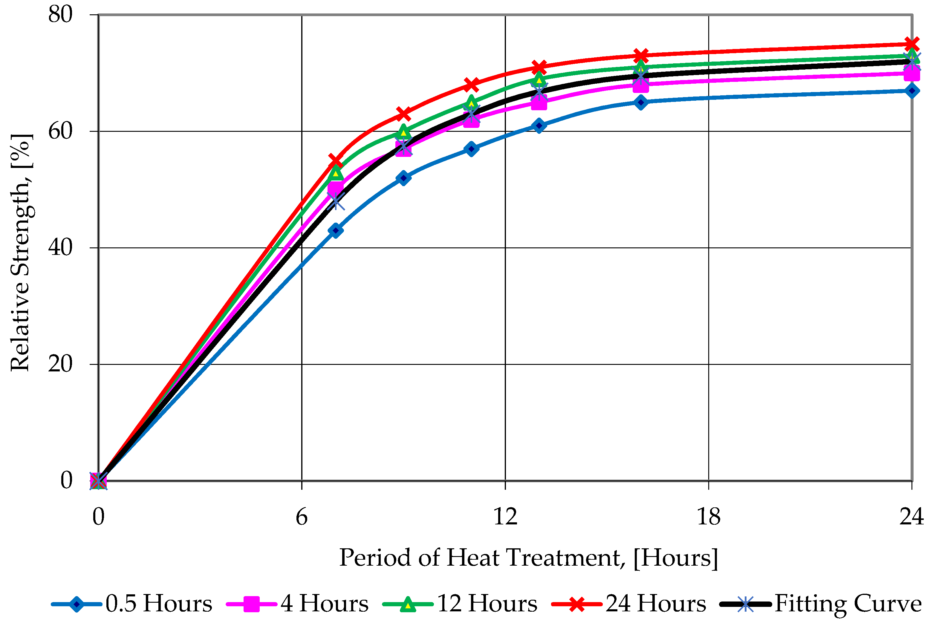
| Period of HT, [Hours] | Relative Strength of ECC at Different Cooling Periods | |||
|---|---|---|---|---|
| 0.5 h | 4 h | 12 h | 24 h | |
| Heat-Treated ECC Specimens with 0% BF | ||||
| 7 | 0.4301 | 0.5002 | 0.5299 | 0.5499 |
| 9 | 0.5202 | 0.5699 | 0.6001 | 0.6303 |
| 11 | 0.5634 | 0.6201 | 0.6502 | 0.6799 |
| 13 | 0.6013 | 0.6498 | 0.6702 | 0.7102 |
| 16 | 0.6412 | 0.6799 | 0.7085 | 0.7301 |
| 24 | 0.6621 | 0.6999 | 0.7288 | 0.7501 |
| Heat-Treated ECC Specimens with 0.45% BF | ||||
| 7 | 0.4309 | 0.5001 | 0.5304 | 0.5502 |
| 9 | 0.5199 | 0.5707 | 0.5999 | 0.6299 |
| 11 | 0.5596 | 0.6203 | 0.6498 | 0.6818 |
| 13 | 0.6026 | 0.6501 | 0.6746 | 0.7113 |
| 16 | 0.6406 | 0.6814 | 0.7098 | 0.7309 |
| 24 | 0.6609 | 0.7021 | 0.7304 | 0.7498 |
| Heat-Treated ECC Specimens with 0.9% BF | ||||
| 7 | 0.4298 | 0.4998 | 0.5298 | 0.5499 |
| 9 | 0.5201 | 0.5702 | 0.5997 | 0.6308 |
| 11 | 0.5611 | 0.6207 | 0.6501 | 0.6802 |
| 13 | 0.6018 | 0.6493 | 0.6718 | 0.7098 |
| 16 | 0.6409 | 0.6797 | 0.7104 | 0.7298 |
| 24 | 0.6618 | 0.6999 | 0.7288 | 0.7509 |
| Heat-Treated ECC Specimens with 1.2% BF | ||||
| 7 | 0.4302 | 0.5012 | 0.5307 | 0.5506 |
| 9 | 0.5213 | 0.5708 | 0.6003 | 0.6314 |
| 11 | 0.5629 | 0.6199 | 0.6501 | 0.6817 |
| 13 | 0.6094 | 0.6488 | 0.6743 | 0.7108 |
| 16 | 0.6428 | 0.6802 | 0.7089 | 0.7304 |
| 24 | 0.6609 | 0.7024 | 0.7296 | 0.7518 |
| Period of HT [Hours] | Average Relative Strength of ECC at Different Cooling Periods (Standard Deviation of Test Data) | |||
|---|---|---|---|---|
| 0.5 h | 4 h | 12 h | 24 h | |
| 7 | 0.43 (0.57) | 0.50 (0.72) | 0.53 (0.71) | 0.55 (0.69) |
| 9 | 0.52 (0.74) | 0.57 (0.69) | 0.60 (0.51) | 0.63 (0.57) |
| 11 | 0.56 (0.58) | 0.62 (0.48) | 0.65 (0.66) | 0.68 (0.67) |
| 13 | 0.60 (0.71) | 0.65 (0.52) | 0.67 (0.57) | 0.71 (0.49) |
| 16 | 0.64 (0.68) | 0.68 (0.58) | 0.71 (0.59) | 0.73 (0.63) |
| 24 | 0.66 (0.72) | 0.70 (0.67) | 0.73 (0.52) | 0.75 (0.52) |
Publisher’s Note: MDPI stays neutral with regard to jurisdictional claims in published maps and institutional affiliations. |
© 2020 by the authors. Licensee MDPI, Basel, Switzerland. This article is an open access article distributed under the terms and conditions of the Creative Commons Attribution (CC BY) license (http://creativecommons.org/licenses/by/4.0/).
Share and Cite
Kharun, M.; Klyuev, S.; Koroteev, D.; Chiadighikaobi, P.C.; Fediuk, R.; Olisov, A.; Vatin, N.; Alfimova, N. Heat Treatment of Basalt Fiber Reinforced Expanded Clay Concrete with Increased Strength for Cast-In-Situ Construction. Fibers 2020, 8, 67. https://doi.org/10.3390/fib8110067
Kharun M, Klyuev S, Koroteev D, Chiadighikaobi PC, Fediuk R, Olisov A, Vatin N, Alfimova N. Heat Treatment of Basalt Fiber Reinforced Expanded Clay Concrete with Increased Strength for Cast-In-Situ Construction. Fibers. 2020; 8(11):67. https://doi.org/10.3390/fib8110067
Chicago/Turabian StyleKharun, Makhmud, Sergey Klyuev, Dmitry Koroteev, Paschal C. Chiadighikaobi, Roman Fediuk, Andrej Olisov, Nikolai Vatin, and Nataliya Alfimova. 2020. "Heat Treatment of Basalt Fiber Reinforced Expanded Clay Concrete with Increased Strength for Cast-In-Situ Construction" Fibers 8, no. 11: 67. https://doi.org/10.3390/fib8110067
APA StyleKharun, M., Klyuev, S., Koroteev, D., Chiadighikaobi, P. C., Fediuk, R., Olisov, A., Vatin, N., & Alfimova, N. (2020). Heat Treatment of Basalt Fiber Reinforced Expanded Clay Concrete with Increased Strength for Cast-In-Situ Construction. Fibers, 8(11), 67. https://doi.org/10.3390/fib8110067