Article

Experimental Investigation of Transverse Loading Behavior of Ultra-High Molecular Weight Polyethylene Yarns

1
McNair Aerospace Center, University of South Carolina, Columbia, SC 29201, USA
2
Department of Mechanical Engineering, University of South Carolina, Columbia, SC 29208, USA
*
Author to whom correspondence should be addressed.
Fibers 2020, 8(10), 66; https://doi.org/10.3390/fib8100066
Submission received: 22 September 2020 / Revised: 12 October 2020 / Accepted: 14 October 2020 / Published: 19 October 2020
(This article belongs to the Special Issue Polymer Fibers and Composites)

Abstract

:
Ultra-high molecular weight polyethylene (UHMWPE) Dyneema® SK-76 fibers are widely used in personnel protection systems. Transverse ballistic impact onto these fibers results in complex multiaxial deformation modes such as axial tension, axial compression, transverse compression, and transverse shear. Previous experimental studies on single fibers have shown a degradation of tensile failure strain due to the presence of such multi-axial deformation modes. In this work, we study the presence and effects of such multi-axial stress-states on Dyneema® SK-76 yarns via transverse loading experiments. Quasi-static transverse loading experiments are conducted on Dyneema® SK-76 single yarn at different starting angles (5°, 10°, 15°, and 25°) and via four different indenter geometries: round (radius of curvature (ROC) = 3.8 mm), 200-micron, 20-micron, and razor blade (ROC ~ 2 micron). Additionally, transverse loading experiments were also conducted for a 0.30 cal. fragment simulating projectile (FSP) and compared to other indenters. Experimental results show that for the round, 200-micron indenter, and FSP geometry the yarn fails in tension with no degradation in axial failure strain compared to the uniaxial tensile failure strain of SK-76 yarn (2.58%). Whereas for the 20-micron indenter and razor blade, fibers fail progressively in transverse shear followed by progressive strength degradation of the yarn. Strength degradation of yarn occurs at relatively low strains of 0.6–0.7% with eventual failure of the yarn at approximately ~1.8% and ~1.5% strain for the 20-micron indenter and razor blade, respectively. Breaking angles (range of 10°–30°) are observed to have little effect on the failure strain for all indenter geometries.

1. Introduction

Ultra-high molecular weight polyethylene (UHMWPE) is a linear flexible polymer [1] of C2H4 molecules with a molecular weight of at least three million. It is manufactured using a patented gel-spun process developed by DSM (Dutch State Mines) corporation in Netherlands and is branded under the name Dyneema®. Compared to a melt crystallized block of molecules, the gel spinning and drawing process results in a long chain of parallel molecules in a crystal lattice. This long chain of parallel molecules when oriented along the fiber axis gives UHMWPE (Dyneema) fibers their high tensile strength and stiffness [2]. They are mainly used in the form of textile fabrics and unidirectional composites in a wide range of applications like fishing ropes, tents, golf clubs, cut-resistant gloves, containment systems, and in soft and hard body armor for ballistic applications [3]. Ballistic impact onto personnel protection systems is a complex multiscale problem due to the multiscale hierarchy of the materials, anisotropic material behavior, projectile geometry, impact velocity and boundary conditions. Although this subject has been an active area of research for decades, the fundamental mechanisms, such as material failure, dynamic response and multi-axial loading occurring at different scales during impact are not well understood. Predicting impact performance requires an understanding of the failure of yarns under complex multiaxial loading conditions.
Traditionally, transverse impact onto yarns and fabrics was studied using the classical Smith theory [4,5] as shown in Equation (1). Smith theory proposed that the breaking velocity of the yarn can be predicted in terms of the longitudinal wave speed, “c”, and the uniaxial tensile failure strain, ε, of the material.
V = c 2 ε ε ( 1 + ε ) ε 2
However, several authors [6,7,8,9,10,11] in the literature have reported that the ballistic performance of a fabric or yarn is not solely controlled by the tensile properties of the material. Instead a combination of multitude of factors such as multi-axial loading, stress gradients, inter-filament friction, projectile shape and velocity, boundary conditions etc., contribute towards the ballistic performance of the material. Impact experiments by Hudspeth et al. [12] on Dyneema® SK-76 yarns (1350 dtex) via a round projectile, fragment simulating projectile (FSP) and razor blade showed that the experimental breaking speeds are significantly lower compared to the predictions from Smith theory. For SK-76 yarn, an average tensile failure strain of 2.68% reported by Hudspeth et al., Equation (1) predicts a breaking speed of 1036 m/s, whereas the experimentally measured breaking speeds for the round projectile, FSP and razor blade are in the range of 505 to 750 m/s, 450 to 690 m/s and 190 to 315 m/s, respectively [12]. The range in breaking speeds refers to regime of partial yarn failure. Beyond this range complete failure of yarn on impact is observed for the respective geometries. This premature failure of yarns compared to Smith theory is attributed to the presence of the multi-axial stress states during transverse impact which causes a degradation in the tensile failure strain of the material. Multi-axial stress states are induced in the form of axial tension, axial compression, transverse compression and transverse shear near the projectile-fiber contact zone.
The effects of multi-axial loading on fiber failure strain was first studied by Hudspeth et al. [13] via quasi-static transverse loading experiments of high-performance single fibers using different indenter geometries. Their results indicate that projectile geometry and fiber breaking angle have a significant effect on the axial failure strain of Dyneema® SK-76 fibers loaded via a sharp FSP and a razor blade. Sockalingam et al. have also shown the presence of such multi-axial stresses and stress concentration near the projectile-fiber contact region via three-dimensional finite element models for Kevlar® KM2 [11,14] and Dyneema® SK-76 single fibers [15]. Although, there are several studies in the literature on the effect of multi-axial loading of single fibers, the effect of multi-axial loading on yarns is not very well understood in the literature. Lim et al. [16] in their recent study on Twaron yarns showed that the stress concentration in fibers decreases with an increase in the radius of the curvature of the projectile. In our previous study on Dyneema® SK-76 yarns [17], we observed a significant difference in the mechanical behavior of yarns compared to single fibers under transverse compression. Quasi-static transverse compression of Dyneema SK-76 yarns, unconstrained in the lateral direction, showed less reduction in tensile strength as compared to single fibers when compressed to average nominal strains of 77%. This was attributed to non-uniform loading and significant spreading of fibers within the yarn during transverse compression. We hypothesize that under multi-axial transverse loading yarns exhibit a more complex progressive failure behavior compared to single fibers. In this study, we investigate the behavior of Dyneema SK-76 under multi-axial loading via quasi-static transverse loading using different indenter geometries to create the foundation for a failure model. Besides this, for full-scale fabric models at the yarn scale, failure is generally modeled using a maximum principal stress or maximum principal strain criterion [18,19,20,21] that does not account for the effects of multi-axial stresses observed during loading. The experimental investigation performed in this study can also aid in the development of a multi-axial failure criterion in the future for improved predictions of yarn failure and ballistic performance.
Quasi-static transverse loading experiments on yarns are performed using the experimental methodology reported by Hudspeth et al. for single fibers [13]. Dyneema® SK-76 yarns are transversely loaded via different indenter geometries: a round projectile, 200-micron indenter, 20-micron indenter and a razor blade. For each indenter geometry, transverse loading experiments are performed at various yarn starting angles to induce various failure angles. This is performed to investigate the effect and presence of stress-concentration developed around such indenters through angles that would be produced during transverse impact.

2. Materials and Methods

Dyneema® SK-76 fiber is obtained from DSM Dyneema, Geleen, Netherlands, in the form of a spool of yarn without any twist with properties as presented in Table 1. Quasi-static tension tests of SK-76 yarns at a gage-length of 10 inches yielded a uniaxial failure strain of 3.1% as reported in our previous study [17]. Here, we further that experimental study to determine compliance corrected uniaxial failure strain to use as a baseline for comparison against the quasi-static transverse loading results. Using the same single column tester, Instron Model 5944, as in [17], twelve additional quasi-static tension experiments each were performed at two different gage-lengths (12 inches and 15 inches) for SK-76 yarns. A machine compliance of 0.0028 mm/N was determined based on the method described in ASTM (American Society of Testing Materials) standard C1557 [22]. Correcting the quasi-static tension test results for SK-76 yarns (gage-length = 10 inches) for machine compliance resulted in an average uniaxial failure strain of 2.58%. A similar value for tensile failure strain (2.6%) is reported by Phoenix et al. [23] for SK-76 yarns (1760 dtex) with tensile strength and modulus of 3.4 GPa and 130 GPa, respectively.
The same single column testing system as used for quasi-static tension tests was used for performing quasi-static transverse loading experiments, however, with the pneumatic bollard grips arranged side by side as shown in Figure 1. Transverse loading experiments on yarns were performed at various starting angles for four different indenter geometries: a razor blade (radius of curvature: ROC ~ 2 µm), 20-micron indenter, 200-micron indenter and round projectile (ROC = 3.8 mm) based on the experimental methodology described by Hudspeth et al. [13] for the transverse loading of single fibers. The said geometries were chosen to investigate the effect of indenter geometry on the induced stress or strain concentration in yarn via indenters having tip radii lower than, in the range of, and several orders above the average SK-76 fiber diameter (17 µm). Figure 2 shows the four indenter geometries used in this study. A high strength steel alloy was used to make the round projectile, 200-micron and 20-micron indenter. High carbon steel razor blades (Personna, Part#: 94-0152) were used for the razor experiments. Except for the round projectile, no other indenter was reused between experiments.
For each indenter geometry, transverse loading experiments were performed at several different starting angles. The starting angle ( θ s t a r t ) is defined as the angle between the yarn and the horizontal axis as depicted in the schematic in Figure 3. Different starting angles are achieved by controlling the vertical position, “hinitial”, of the indenter via the system crosshead whilst constraining the movement of bollard grips in the horizontal direction. As the indenter is moved to the required position, “hinitial” (found using trigonometric relations for a given starting angle), the yarn ends can slip within the grips. Once the desired starting angle configuration is obtained, one of the pneumatic bollard grips is closed using a foot pedal as the other end of the yarn is pulled slightly before closing the other grip. This results in a slack start procedure by leaving slack on one side of the yarn as described in the ASTM standard D7269-07 [24] for a yarn uniaxial tension experiment. A small preload of approximately 1 N is applied to the yarn before starting the test to ensure contact between the yarn and the indenter. As the crosshead travels upwards, the indenter loads the yarn in the transverse direction until failure. The failure angle or breaking angle ( θ f a i l ) is calculated based on the output crosshead displacement (hfinal) at failure and trigonometric relations.
For the round projectile, ten tests each were conducted at starting angles of 15°, 20°, and 25°. For the 200-micron indenter and 20-micron indenter, ten tests each were conducted at starting angles of 15° and 25° and starting angles of 10° and 25°, respectively. Out of those ten tests, five were done with a camera to investigate the mark-tracking method for measuring strains as described in Section 3.3. For razor blade, eight tests each were conducted at starting angles of 5°, 10°, 15°, and 25°. Except for the round projectile, no other indenter was reused between tests to minimize the influence of change in indenter geometry due to loading. Quasi-static transverse loading experiments were performed at a displacement rate of 171.5 mm/min for the round projectile and 200-micron indenter and 30 mm/min for the 20-micron indenter and razor blade, respectively. All yarn specimens were end tabbed using cardstock paper for easy handling of specimens. A double-sided carbon tape (Tadpella) was applied to the gripping platens and yarn ends were coated in athletic rosin powder to minimize fiber slippage from within the grips.

3. Results

3.1. Transverse Loading—The Effect of Angle and Indenter Geometry

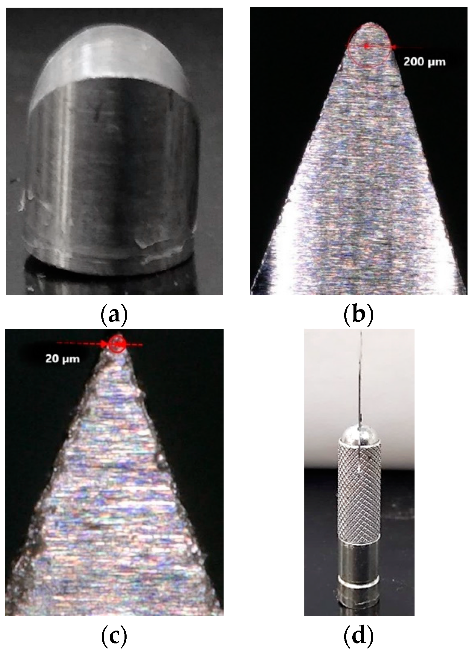
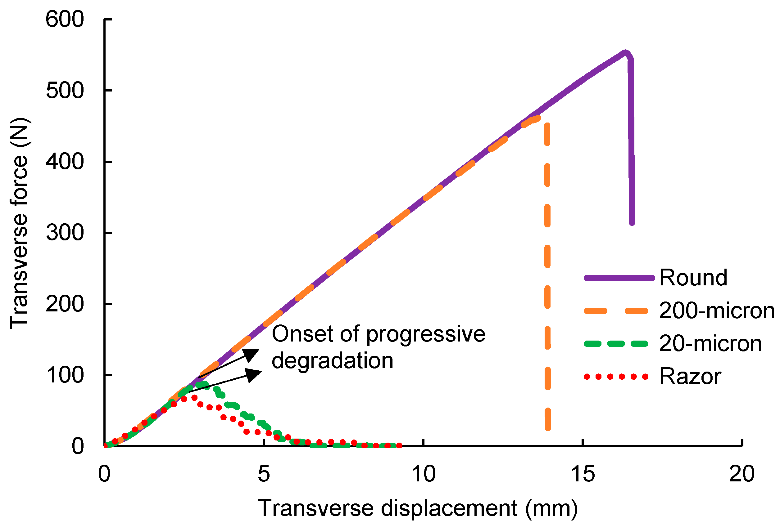
Figure 4 shows a force-displacement response for transverse loading for various indenter geometries. For conciseness, only a representative transverse force-displacement response at a starting angle of 25° is presented for the various indenter geometries. As seen from the figure, transverse failure loads decrease with increasing sharpness of the indenter geometry. A maximum transverse peak load is observed for the round projectile and is approximately 10 times higher than the peak load for the razor blade. Such a trend in transverse loads was also noted by Lim et al. [16] for Twaron yarns subjected to transverse loading via various indenter geometries. Figure 4 also highlights the differences in yarn failure observed for the different indenter geometries.
While instantaneous brittle failure is observed for the round projectile and 200-micron indenter on reaching the peak load, progressive failure occurs for the 20-micron indenter and razor blade. These differences in failure mode are more vividly captured in an experimental video which is attached to this study as supplementary information (see Supplementary Materials). For the round projectile and 200-micron indenter, the yarn snaps back and forms a bulbous mass at failure. Such a failure was also observed for the uniaxial tensile failure of yarn in our previous study [17]. Whereas for the 20-micron indenter and razor blade, individual fibers fail progressively in a cutting-type manner under transverse shear. For these indenters, two phenomena are observed during loading: progressive fiber failure and progressive degradation in load-carrying capacity of yarn as seen from Figure 4. As the load increases, individual fibers start failing in a progressive manner and on reaching peak load, a cluster of fiber breaks is observed with progressive degradation in the load carrying capacity of the yarn.
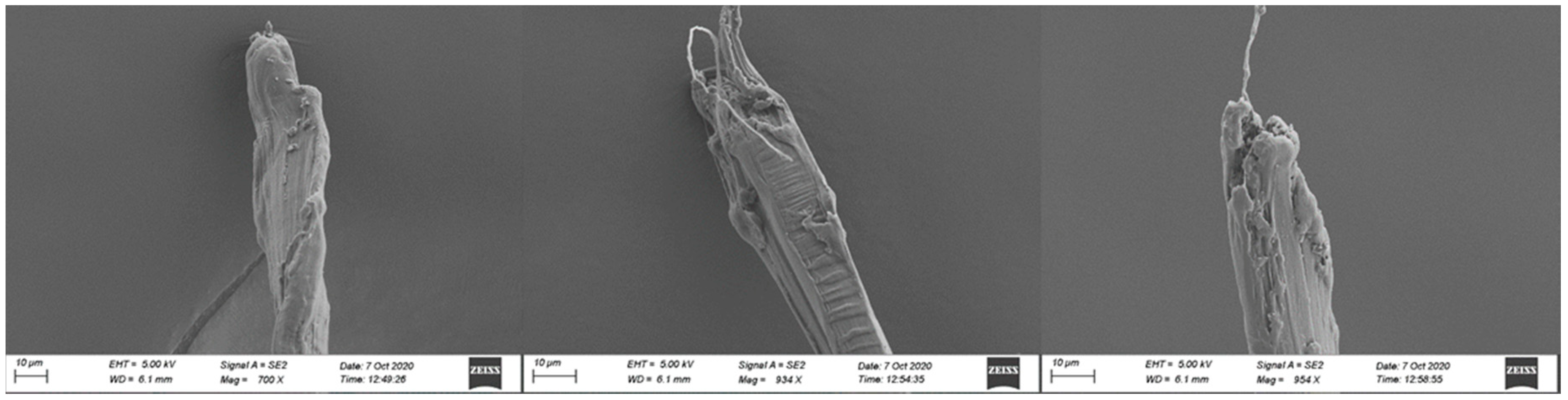
Figure 5 and 
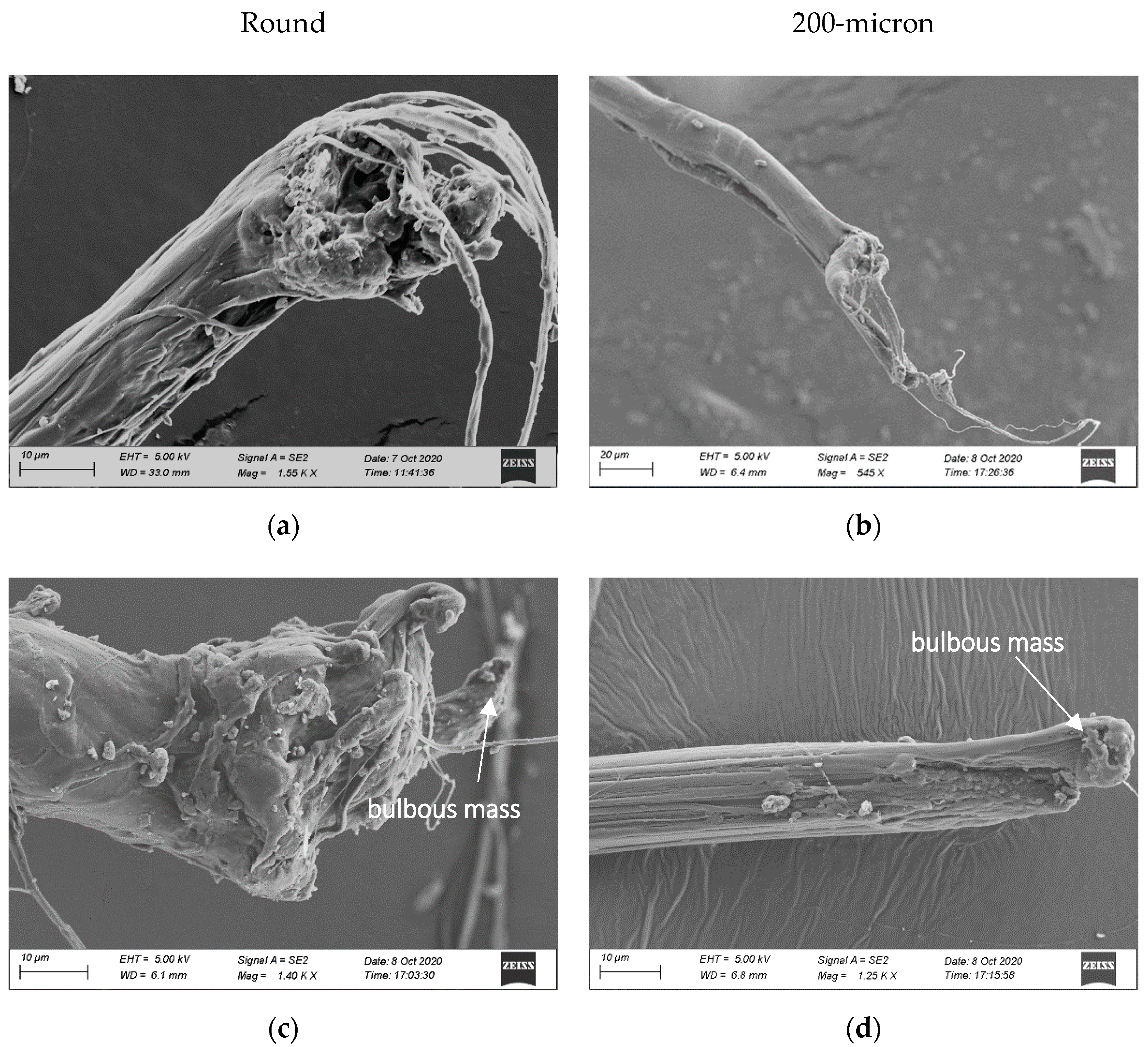
Figure 6 show post-mortem images of fiber failure surface for different indenter geometries for a starting angle of 25°. Multiple fibers are extracted from a failed yarn specimen and sputter-coated with gold-palladium (Au-Pd) particles before being imaged under a Zeiss FE 500 SEM acquired from Carl Zeiss Microscopy LLC, White Plains, NY, US. As seen from Figure 5, for the round projectile fiber failure occurs mainly by axial splitting of fibrils or fibrillation. However, some fibers also show a flattening of fibrils along with fibrillation as depicted in Figure 5e. Hudspeth et al. [13] also report a similar failure surface for SK-76 single fibers transversely loaded by round projectile. For the 200-micron indenter, fibers mainly fail via flattening and fibrillation, as seen from Figure 5b,d,f. Similar failure mechanisms are also observed for tensile failure of high modulus polyethylene fibers (HMPE) as reported by Languerand et al. [25]. From the experimental video for the round projectile and 200-micron indenter it was observed that fibers snap back and form a bulbous mass at failure. This phenomenon can also be seen in the failure surface images for both indenters in Figure 5c,d.
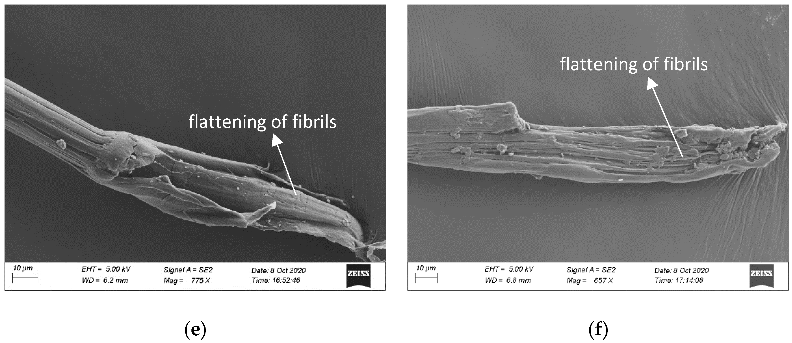
Post-mortem images of fiber failure surface for the 20-micron indenter and razor blade are very similar. For both geometries, fibrils seem to have been cut through via a localized transverse shear, as indicated by a flat failure surface. Although for the 20-micron indenter, a tensile failure of some fibrils is observed at one end of the failed fiber as shown in all its Figure 6a,c,e. Gao et al. [26,27] and Hudspeth et al. [13] have also reported similar failure images in their study on transverse failure of SK-76 fibers. However, the failure surfaces shown here for the 20-micron indenter (for failure angles ~26° (as shown later in Figure 9) are in contrast with those reported in [13] for SK-76 single fibers which fail mainly via fibrillation for failure angles up to 40° and shear failure for failure angles at 50°. One potential reason for this could be the difference in fiber–indenter contact evolution when transversely loading yarns versus single fibers. Compared to single fibers, the contact conditions of the yarn are more complex involving several layers of fibers. A more detailed understanding of the contact conditions via three-dimensional finite element models is required to better understand this difference in failure mechanism between single fibers and yarns.
For the razor blade, however, the failure mechanism for the fiber seems to depend on the fiber location. Some fibers are completely cut through, as shown in Figure 6b, whereas in some fibers, fibrils fail via both cutting (shearing) and fibrillation as shown in Figure 6d,e. This type of a combined failure mechanism observed for both these indenters can be explained via the results of a three-dimensional finite element study of multi-axial loading of SK-76 single fiber conducted by Sockalingam et al. [15]. Their results indicate that near the fiber–indenter contact interface the fiber experiences axial compression, transverse compression and transverse shear whereas away from the contact interface the fiber is under tension. This can explain why some fibrils at one end of the fiber fail via fibrillation or in tension whereas other fibrils are cut-through or sheared. Additionally, kink bands are observed on the fiber surface, as annotated in Figure 6b. These kink bands are formed as a result of an axial compressive wave generated at the clamped end due to fiber recoil at failure [28].
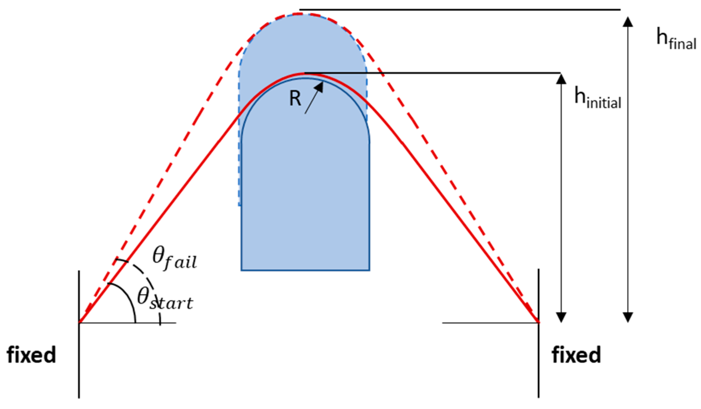
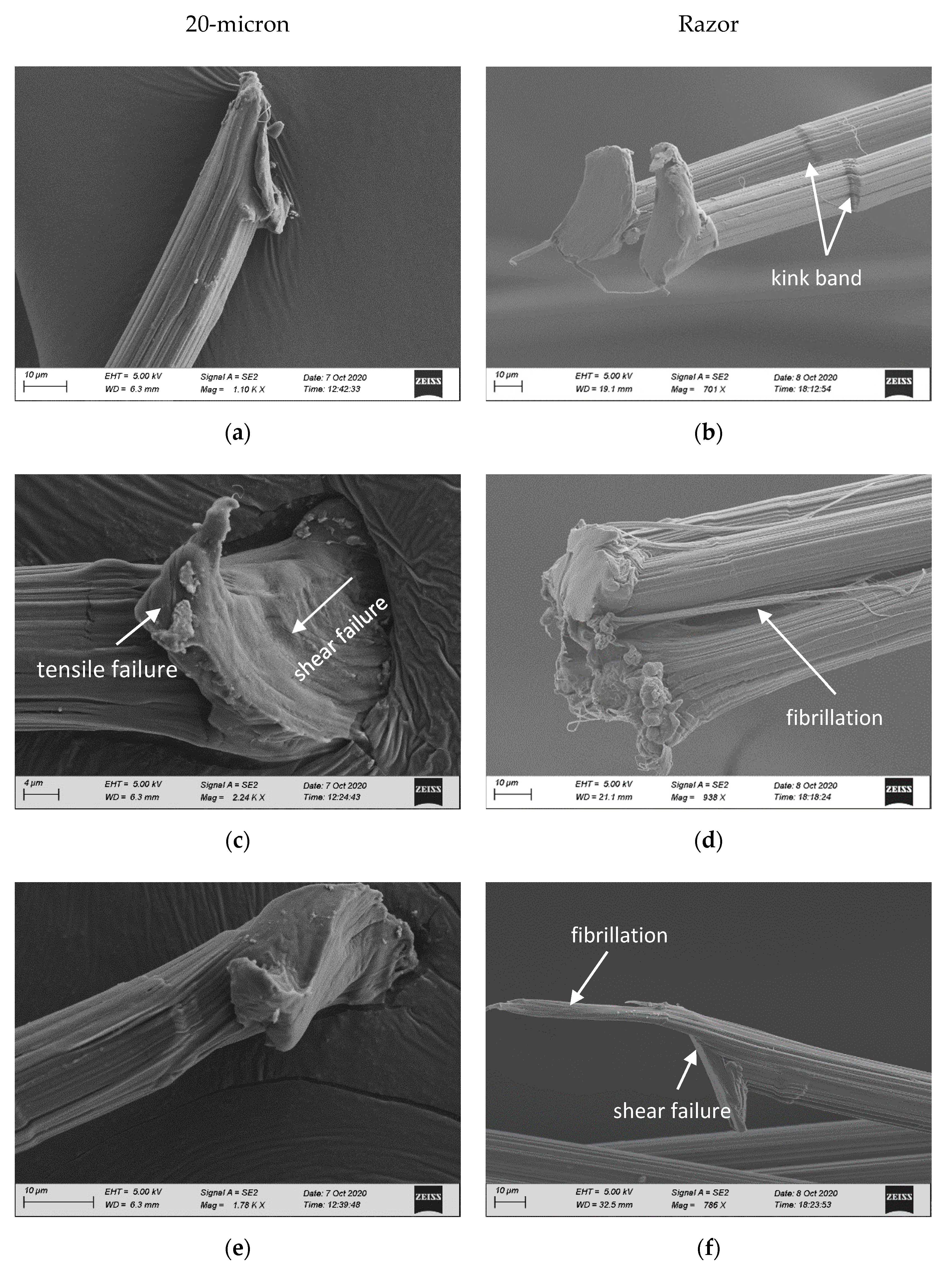
The effect of multi-axial loading on axial tensile properties is investigated by transforming the transverse load and displacement results to axial load and displacements in the fiber direction using the free body diagram shown in Figure 7. Axial stress, σ, is calculated as σ =   F A o r i g i n a l   y a r n     c . s   a r e a , where FA is the axial load given by F A =   F T 2 s i n θ , FT and θ are the transverse load and current angle at a given time, respectively, and yarn cross-sectional area is taken as 0.1796 mm2 (see Table 1). Similarly, the output cross-head displacement is transformed to axial displacement to determine axial strain, ε, as ε =   L f i n a l L i n i t i a l L i n i t i a l , where L i n i t i a l and L f i n a l is the initial and final length of the yarn after being subjected to a transverse displacement, “u”, respectively.
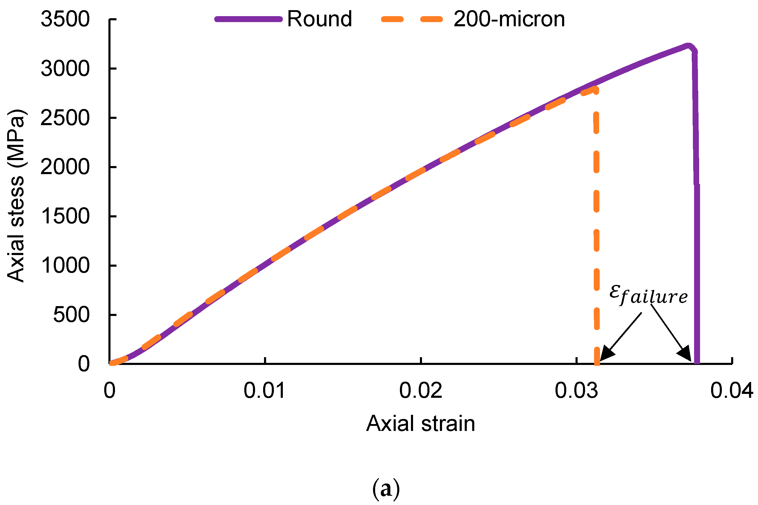
Figure 8 shows a representative axial stress vs. strain response for various indenter geometries at a starting angle of 25°. As observed for transverse loads, the peak axial stress decreases with increasing sharpness of the indenter geometry. Figure 8 also delineates strains ε o n s e t and ε f a i l u r e on the stress–strain curves which will be useful for discussion in the later sections. ε f a i l u r e refers to the strain at complete failure of yarn and ε o n s e t 
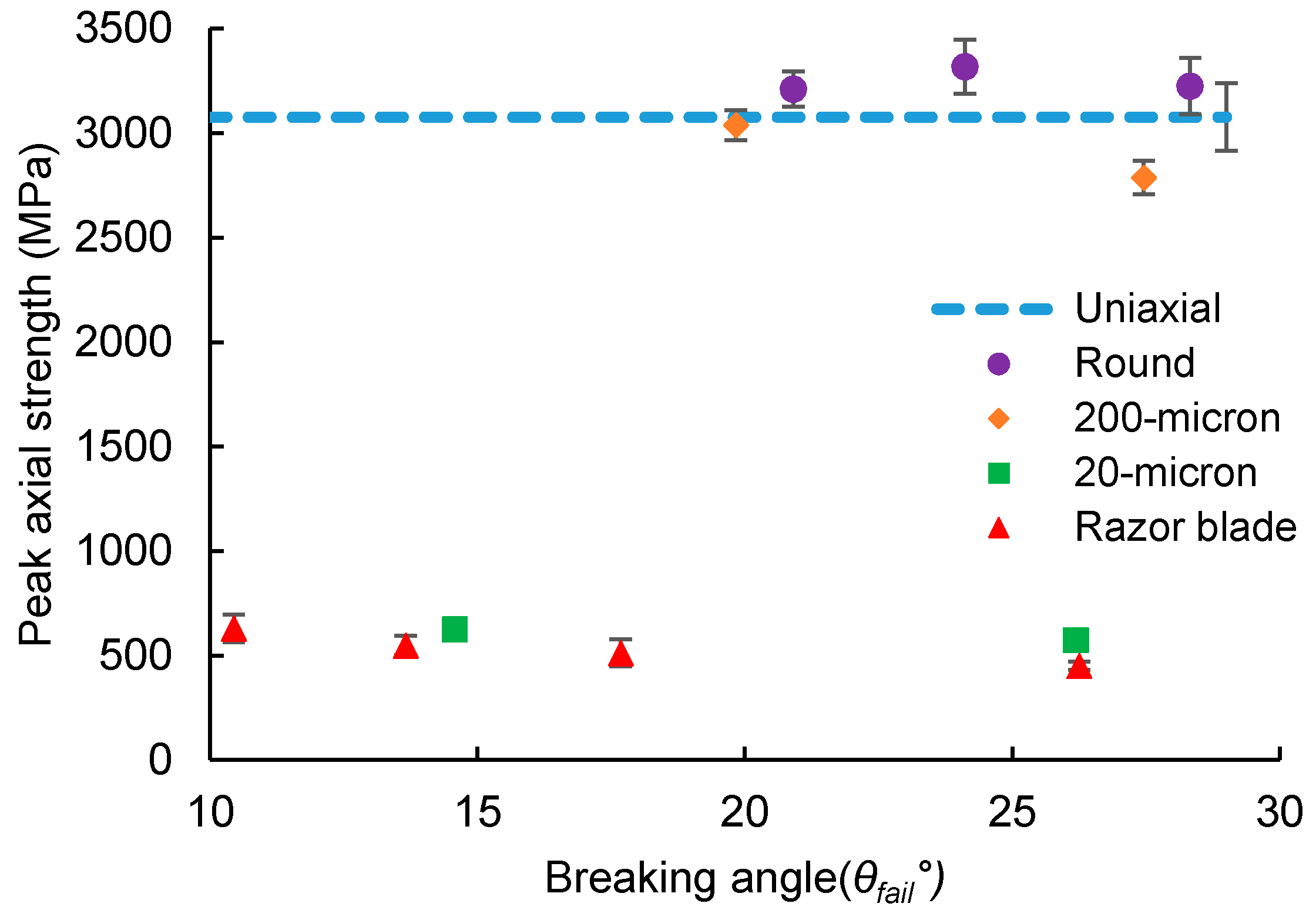
refers to the strain at onset of strength degradation observed in the yarns. The variation in axial strength with breaking angle for the different indenter geometries is shown in Figure 9. Note that axial strength is calculated at peak load for all indenter geometries. The breaking angle, as described earlier, is the angle at which the yarn fails completely. Due to progressive fiber failure and strength degradation observed for the 20-micron indenter and razor blade, breaking angle for these indenters is determined at a point when the transverse load drops to 1 N.
As seen from Figure 9, the yarn breaking angle has a negligible effect on axial strength for all indenter geometries. Further, transverse loading via the round projectile leads to no degradation in the axial failure strength compared to the uniaxial tensile strength of SK-76 yarn (3077 MPa). A slight decrease in axial strength is observed for the 200-micron indenter with an increase in the breaking angle, however, it may not be statistically significant. The greatest degradation in axial strength is observed for the 20-micron indenter and razor blade. Axial strength degrades by approximately 80% compared to the yarn uniaxial tensile strength for these geometries. The axial failure strain results for the different geometries are presented in
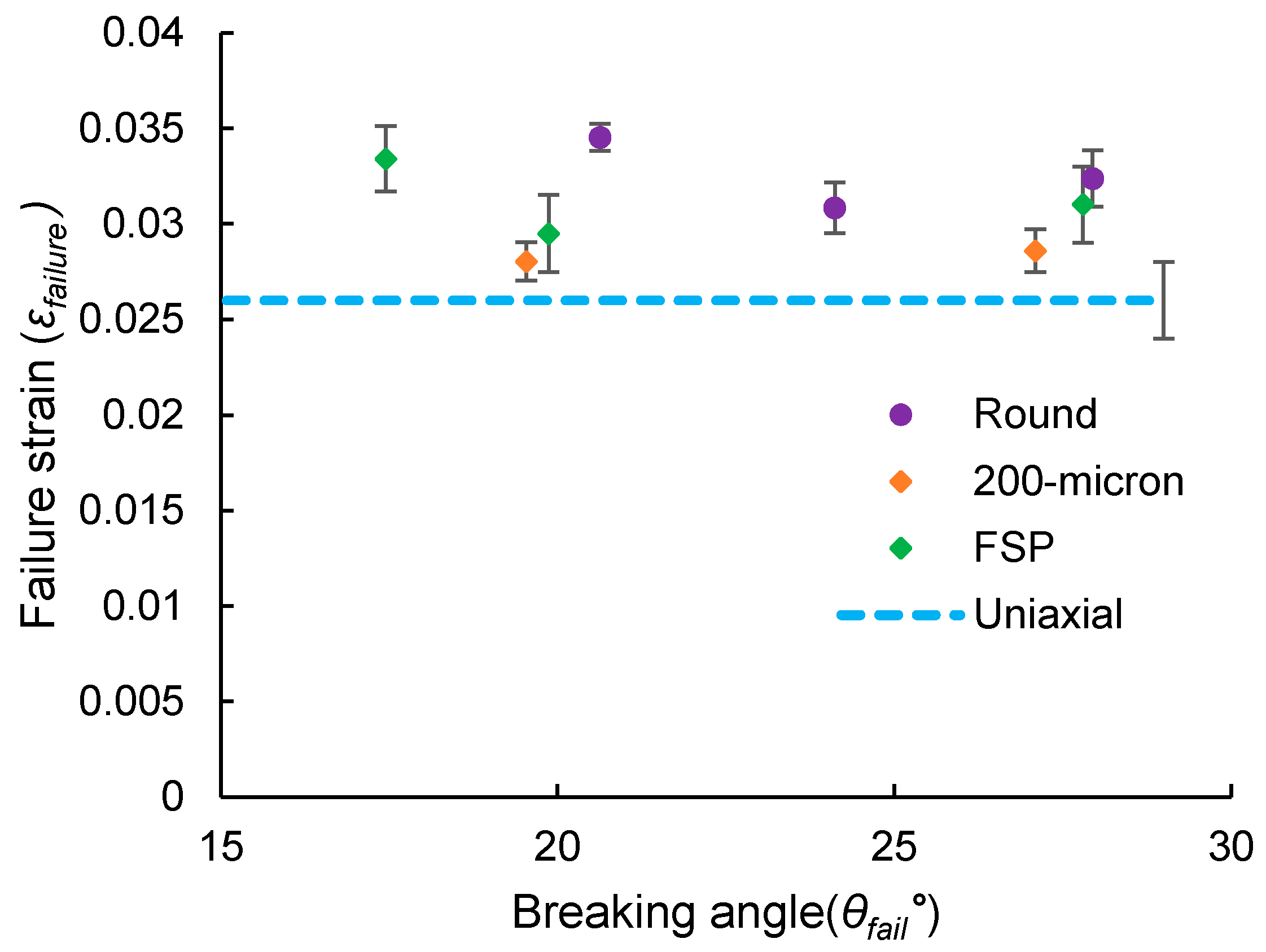
 Figure 10.
As seen from Figure 10, yarn breaking angle has a negligible effect on the axial failure strain ( ε f a i l u r e ). As found for the axial strength results, transverse loading via the round projectile and the 200-micron indenter cause no degradation in the axial failure strain whereas for the 20-micron indenter and the razor blade, failure strain degrades to approximately ~1.8% and ~1.5% compared to the uniaxial tensile failure strain (compliance corrected) of 2.58%. It is important to note here that the failure strains presented in 
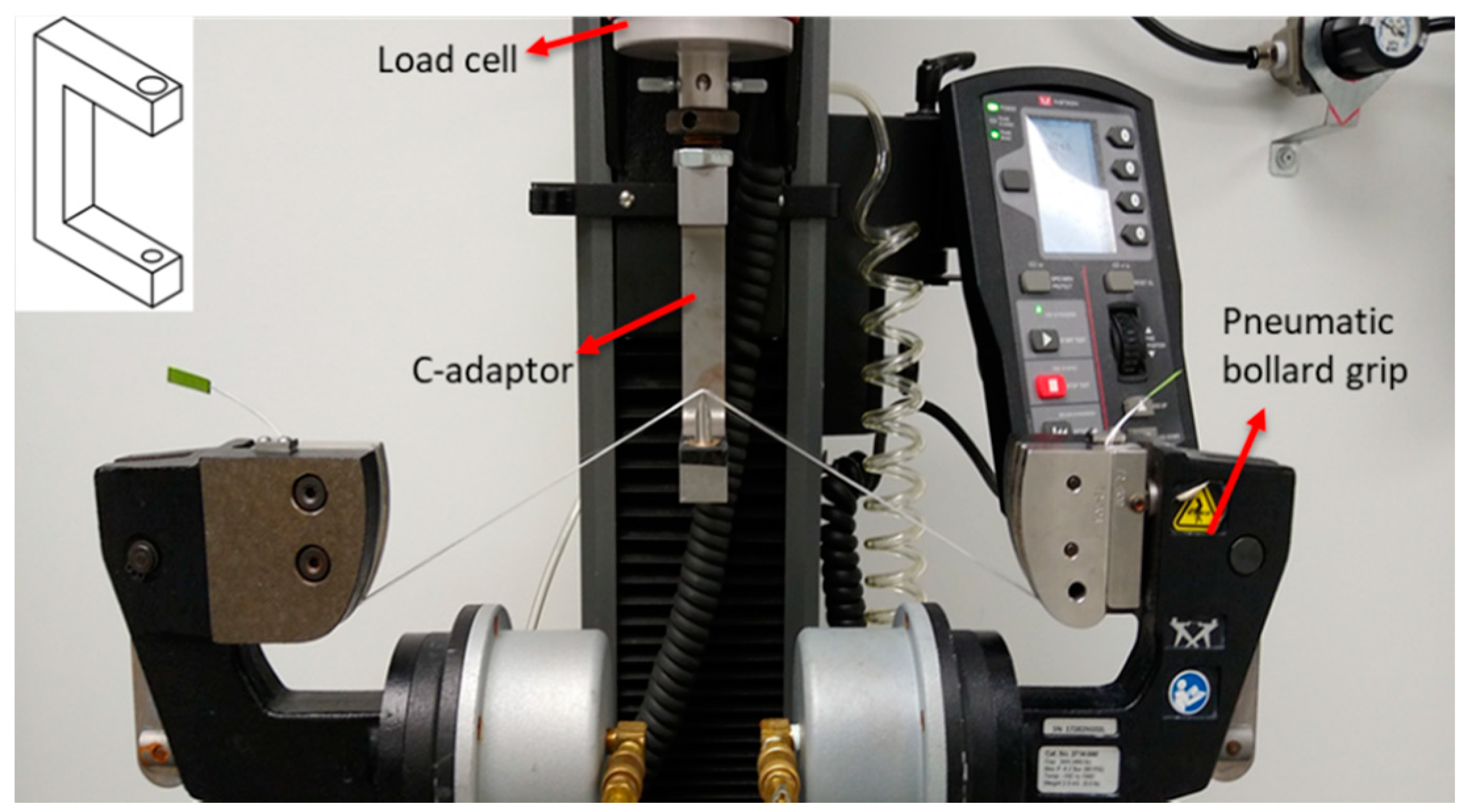
Figure 10 for the round projectile and the 200-micron indenter represent compliance corrected strains. A compliance value of 0.0028 mm/N, the same as that found for tensile tests, was applied to correct the strains. It was not possible to correct the failure strains for the 20-micron indenter and the razor blade due to the progressive failure of yarns observed for these indenters. Although corrected for compliance, failure strains for the round projectile and the 200-micron indenter appear slightly higher than the uniaxial failure strain as the transverse experimental system is understood to be more compliant than the uniaxial system. In a transverse loading experiment, the bollard grips are arranged side by side (see Figure 1) and thus do not contribute towards the total machine stiffness compared to an uniaxial tension system where the grips are arranged vertically and connected to the system crosshead.
The axial strength and failure strain results from Figure 9 and Figure 10 indicate that indenter geometry plays a significant role in the strength or strain degradation of yarns compared to yarn breaking angle. The tip radius of the 20-micron indenter and razor blade is on the same order as the average fiber diameter (17 µm) of a SK-76 single fiber. This causes a significant stress or strain concentration in the indenter–fiber contact zone unlike the 200-micron indenter and round projectile whose tip radii are significantly larger than the average fiber diameter and thus act as blunt indenters. This also explains the brittle and tension type of failure observed for the round projectile and the 200-micron indenter. It is worth noting here, that although the average failure strains are approximately ~1.8% and 1.5% for the 20-micron indenter and razor blade, the strength degradation of the yarn begins at much lower strains ( ε o n s e t ) of approximately 0.6–0.7% for both geometries, as depicted in Figure 8. It is seen from the experimental video that progressive failure of fibers begins before the onset of strength degradation. This suggests that fibers which are initially in direct contact with the indenter tip begin to fail under transverse shear as the load increases. Whereas fibers away from the yarn–indenter contact region may experience a combined loading of transverse compression, shear and tension. This could lead to fibrillation of the fibers away from the contact region allowing the yarn to carry further load. This is also seen from the fiber failure surfaces presented in Figure 6, which show that some fibers are cut through completely compared to others which fail in both shear and fibrillation. Therefore, the fibers initially in direct contact with the indenter control the peak load carried by the yarn under transverse shear, thereby characterizing the yarn strength in shear. The strength degradation and progressive final failure of fibers is probably controlled by the layers of the fiber away from the contact region experiencing a combined loading, thereby characterizing the yarn toughness in shear. A finite element model of yarn modeled as bundle of fibers subjected to transverse loading via the 20-micron indenter or the razor is required to establish more detailed insights into the yarn failure process for these indenter geometries.
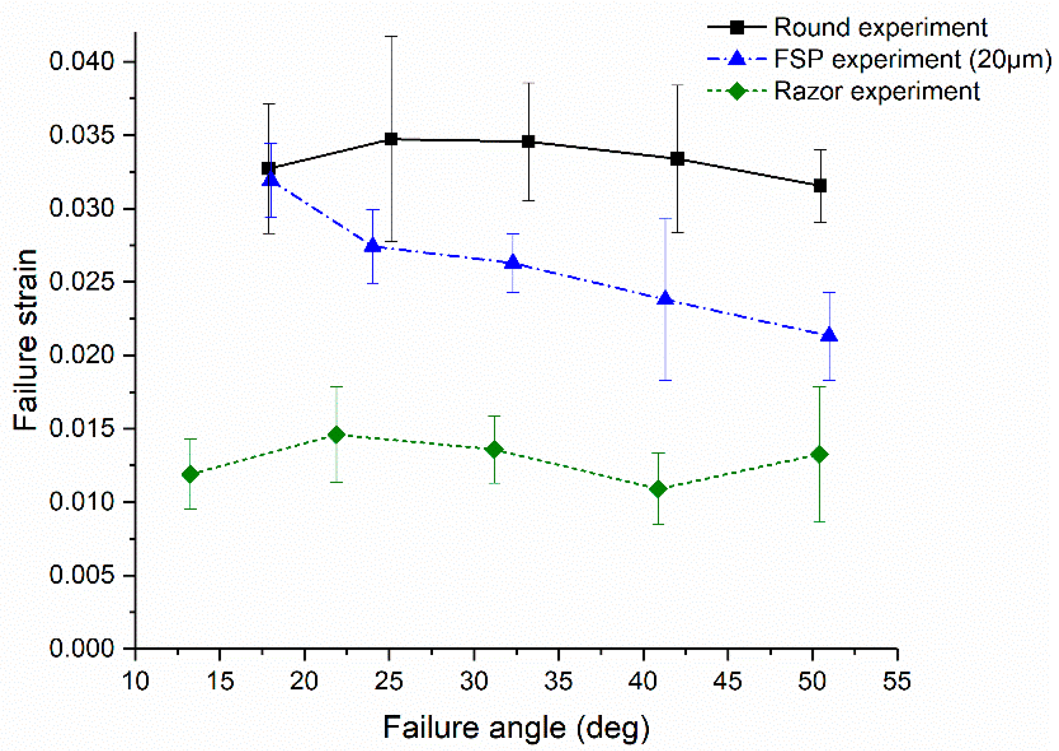
Figure 11 shows the failure strain results from SK-76 single fiber transverse loading experiments conducted by Hudspeth et al. [13]. The reported failure strains in [13] were also determined based on the transverse displacement output and geometry of the experimental system. Comparing Figure 9 and Figure 10, it is seen that round projectile and razor blade display similar trends with breaking angle for failure strain for both yarn and single fiber, respectively. A major difference in the failure strain response between the yarn and the single fiber is, however, observed for the 20-micron indenter or FSP geometry. As shown in Figure 11, the FSP geometry used for single fiber experiments [13], had a corner radius of 20 µm and is comparable with the 20-micron indenter investigated in this study. While progressive degradation in failure strain with an increase in breaking angle is observed for SK-The 76 single fiber breaking angle is seen to have a little effect on yarn failure strain for the 20-micron indenter. Yarn axial strength and strain results (Figure 9 and Figure 10) suggest that the tip radii ≥200 µm yarn exhibits a tensile failure, whereas for tip radii ≤ 20 µm the yarn exhibits a more complex failure process involving progressive failure and strength degradation. This may be the reason why a trend in failure strain with breaking angle is not observed for yarns for the 20-micron indenter unlike single fibers. Additional experimental data at a wide range of angles for a range of different tip geometries (20 µm < R < 200 µm) are also required along with finite element (FE) models to get better insights into yarn response under transverse loading.

3.2. Transverse Loading Experiments Using 0.30 Caliber FSP

For completeness, we also investigated yarns subjected to transverse loading using a 0.30 caliber FSP made to specification MIL-DTL-46593B. As with other indenters, transverse loading experiments for FSP were performed at various starting angles of 15°, 20°, and 25°. Failure strains for 0.3 cal. FSP were also corrected for compliance like those for the round projectile and razor blade and are shown in Figure 12. Failure strain results for 0.3 cal. FSP compare very well with those for the round projectile and 200-micron indenter. There is no degradation in failure strain observed with breaking angle for FSP compared to the uniaxial failure strain of the yarn. This may be because the tip radius of FSP geometry may be relatively larger than the fiber diameter and is thus unable to induce any strain concentration in the fibers. This is also confirmed from the microscope images of the 0.30 cal. FSP tip, as shown in Figure 13. The radius of curvature of the tip, as measured using an optical microscope, is approximately 200 µm, the same as that of the 200-micron indenter used in this study. Post-failure images of fracture surface for FSP geometry, as shown in Figure 14, are similar to those observed for the 200-micron indenter. Fibrillation along with the flattening or thinning of fibrils seems to be the main mechanism of failure like the 200-micron indenter.

3.3. Investigating Mark-Tracking Technique to Measure Strains

The failure strains presented so far in this work were calculated by transforming the output transverse displacements to axial displacements (displacement in the fiber direction) based on the geometry of the experimental system. However, directly measuring specimen displacement is a more accurate method of determining strains. Recently, Wang et al. [29] used a mark-tracking technique to measure the tensile strains of spectra 1000 warp and weft yarns at different strain rates. It involved measuring tensile strains by capturing images of marked yarn specimens at regular intervals and then analyzing the captured images using ImageJ software. It offered a way of directly measuring the strains without having to correct for machine compliance.
Therefore, we sought to use the said mark-tracking (MT) technique and adapt it to our transverse loading experiments in order to obtain better estimates of yarn failure strain. Similar as the mark tracking technique described in [29], three marks were placed on a Dyneema
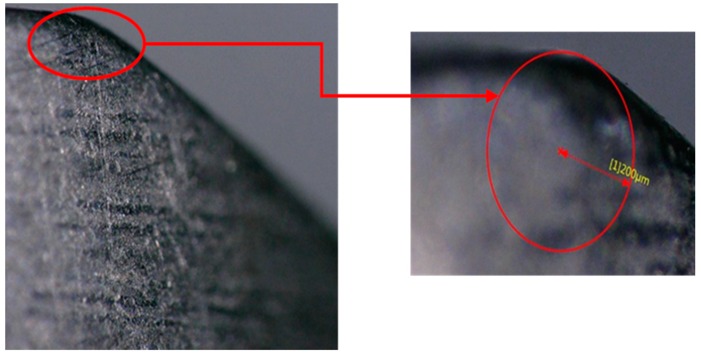
® SK-76 yarn using a 0.30 mm tip SAKURA micron pen at approximately two inches from each other, as shown in Figure 15. A Vernier caliper was used to measure the distance between the inside edges of the marks before the experiment for image calibration. A new series of five transverse loading experiments were conducted for the 200-micron indenter and the 20-micron indenter using the marked yarn specimens. A FLIR greyscale 12MP camera was used to capture the images of the yarn during the experiment at every 100 ms. Captured images were analyzed using ImageJ software to determine the displacement of the marks and hence calculate strains.
Figure 15 depicts two images: before the test and near failure for the 200-micron indenter. Since the images were captured at low resolution it was difficult to accurately measure the displacement of each mark. Thus, the strains were calculated based on the displacement of the outer edges of the first and the last mark, as shown in Figure 15. It must be noted that the mark-tracking technique described here was used only for a preliminary study to investigate its viability for measuring strains during transverse loading. Hence for simplicity, effects of image noise, image distortion and out of plane displacement were not accounted for when calculating strains.
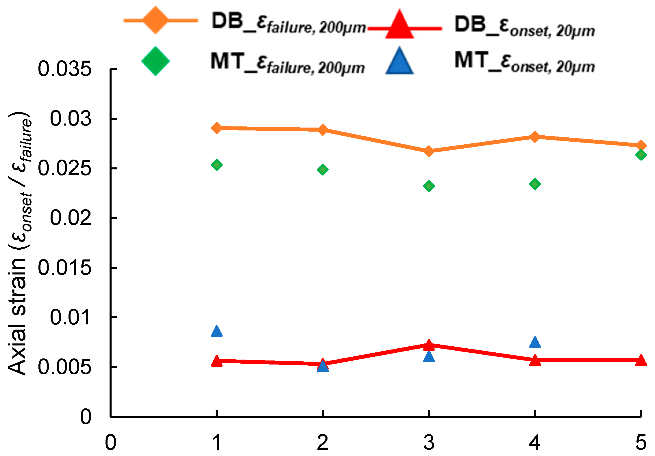
Figure 16 presents a comparison between the axial strains calculated using mark-tracking (MT) method and displacement-based (DB) method for 200-micron and 20-micron indenter at 15° and 25° starting angles, respectively. The mark-tracking and displacement-based method is referred to in the plot as MT and DB for brevity. Since compliance effects are minimized while employing MT technique, it results in more precise strain measurements for the 200-micron indenter compared to the DB technique. Failure strains measured for 200-micron indenter via MT technique are similar to the uniaxial tensile failure strain (2.58%) which is as expected given the tensile failure of yarn under transverse loading by this geometry.
For the 20-micron indenter, the images of the yarn near failure were not suitable for image analysis as the marks faded away with the progressive failure of fibers. Therefore, for the 20-micron indenter, an image close to the onset of strength degradation was analyzed and reported in Figure 16 alongside onset strains obtained from the (DB) method (see Figure 8b). As shown in Figure 16, both the methods give similar strain results for the 20-micron indenter. This may be because the axial displacement of fibers is minimal during loading via the 20-micron indenter as it is found to fail in transverse shear. Besides, calculating the strains for the 20-micron indenter was difficult from images as the fibers seem to rotate during loading, which may be an effect of transverse shear. Thus, a more detailed investigation is required to develop an accurate method to measure strains based on the mark-tracking approach described here. Effects of image noise, image distortion and out of plane displacements due to loading need to be considered in order to obtain better measurements of axial strain.

3.4. Effect of Multi-Axial Stress States on Yarn Breaking Speeds

The axial failure strains determined in this study can be employed in Equation (1) from Smith theory to predict the yarn breaking speeds for different indenter geometries. However, this leads to significant over-prediction of the breaking speeds compared to the experimental breaking speeds [12,23], as these strains do not account for the dynamic effects due to impact.
Fiber scale impact models by Sockalingam et al. [11] have shown that transverse impact onto yarns leads to fiber bounce and complicated wave kinematics in the form of flexural and spreading waves in fibers. This causes a significant increase in the axial strain concentration in the fiber cross-section at the location of failure. They have also shown via single fiber impact models [30] that the dynamic strain concentration factors are approximately twice that of their static counterparts for Kevlar® KM2. Besides, for UHMWPE Dyneema® SK-76 fibers tensile failure strains decrease with increasing strain rates, as reported by Sanborn et al. [31] and Thomas [32]. Therefore, the dynamic failure strains for transverse loading are expected to be lower than the quasi-static strains found in this study.
To quantify the effects of dynamic loading on failure strain, quasi-static uniaxial tensile failure strains are compared with transverse dynamic failure strains for round projectile in literature. This is done with keeping in mind that the geometry effects of round projectile on failure strain are negligible and the degradation in failure strain compared to the uniaxial failure strain is due to the dynamic effects on impact. Hudspeth et al. [12] and Phoenix et al. [23] in the literature have reported failure strains of 1.37% and 1.3% for SK-76 yarns (1350 dtex and 1760 dtex, respectively) impacted via round and saddle-shaped projectiles compared to the quasi-static uniaxial failure strains of 2.68% and 2.6%, respectively. The saddle-shaped geometry used by Phoenix et al. in [23] is a modified version of a round projectile to minimize slippage of the yarn from the projectile surface during impact.
Comparing the above-mentioned dynamic strains to the quasi-static uniaxial tensile failure strains gives a ratio of two between quasi-static to dynamic strains. The quasi-static axial failure strains in this study are corrected using this scale factor ( ε d y n a m i c =   ε q u a s i s t a t i c 2 ) and are used to predict the yarn breaking speeds, as shown in Table 2. Table 2 also shows the breaking speed predictions for the uniaxial failure strain found in this study. When corrected for dynamic effects, the breaking speed results for uniaxial (569 m/s) compare closely with the breaking speed reported for the saddle-shaped projectile (611 m/s) [23]. This is expected as the saddle-shaped projectile induces negligible stress or strain concentration in the yarn due to its geometry. Results for the round projectile, 0.3 cal. The FSP and razor blade are compared against the experimental breaking speeds reported by Hudspeth et al. [12] for the respective geometries. It must be noted here though that the 0.30 cal. FSP geometry used in [12] had a tip radius of 87 µm compared to an FSP with tip radius of 200 µm used in this study. Breaking speeds for the said geometries compare very well with the experimental breaking speed regime as shown in Table 2. Thus, the results indicate that multi-axial loading and dynamic effects due to are major contributors to the lower breaking speeds observed during transverse impact compared to Smith theory.

4. Conclusions

This work investigated the effect of projectile tip geometry and the loading configuration (yarn starting angle and failure angle) on the transverse failure of UHWMPE Dyneema® SK-76 yarns to create the foundation for a failure model. The following indenter geometries were investigated: round projectile, 200-micron indenter, 20-micron indenter, and razor blade. Additionally, yarns were also tested using a 0.30 caliber FSP. As observed for single fibers, yarns fail under tension for the round projectile, 200-micron indenter, and 0.3 caliber FSP without any degradation in the axial failure strain of the material. However, compared to single fibers, yarn failure under the 20-micron indenter and razor blade is more complex, with fibers failing progressively under transverse shear accompanied by progressive degradation in strength carrying capacity of the yarn. Fiber failure surfaces indicate that there is a change in failure mechanism with decreasing curvature of the indenter geometry. Fibers fail mainly via fibrillation for the round projectile, fibrillation and flattening of fibrils for the 200-micron indenter, a combination of fibrillation and shear for the 20-micron indenter, and mainly via shear for the razor blade. In contrast to the single fibers, a decrease in failure strain with breaking angle is not observed for yarns for the 20-micron indenter. This may be due to the continuously evolving fiber–indenter contact conditions encountered during loading for yarn and single fibers. However, additional experimental data with the 20-micron indenter at a range of different angles and finite element models are required to better understand the yarn failure process under transverse loading via the 20-micron indenter and razor blade. The implications of multi-axial loading on the yarn breaking speed were investigated using the axial failure strains determined in this study and the Smith equations. A method to correct quasi-static failure strains for a given projectile for dynamic effects is proposed in order to better predict yarn breaking speeds using Smith equations. The results compare well with the experimental breaking speeds reported in the literature. In the future, we aim to use this experimental investigation along with finite element models to inform and aid the development of a multi-axial failure criterion that can offer improved predictions of yarn failure.

Supplementary Materials

The following are available online at https://www.mdpi.com/2079-6439/8/10/66/s1, Video S1: Yarn failure under different projectiles.

Author Contributions

Conceptualization, S.S.; methodology, S.S. and K.S.; formal analysis, K.S.; investigation, K.S.; data curation, K.S.; writing—original draft preparation, K.S.; writing—review and editing, S.S.; supervision, S.S.; project administration, S.S.; funding acquisition, S.S. All authors have read and agreed to the published version of the manuscript.

Funding

This research was funded by the startup funding provided by the University of South Carolina.

Acknowledgments

Dyneema® SK76 yarns and the projectiles used in this work was provided by DSM Dyneema and ARL respectively and is acknowledged. The useful discussions provided by Ulrich Heisserer, Harm van der Werff and Mark Hazard of DSM Dyneema are gratefully acknowledged. The authors K.S. and S.S. acknowledges the startup funding provided by the University of South Carolina.

Conflicts of Interest

The authors declare no conflict of interest.

References

  1. Afshari, M.; Kotek, R.; Chen, P. High Performance Fibers. In High Performance Polymers and Engineering Plastics; Wiley: Hoboken, NJ, USA, 2011; ISBN 9781118016695. [Google Scholar]
  2. Van Der Werff, H.; Heisserer, U. High-performance ballistic fibers: Ultra-high molecular weight polyethylene (UHMWPE). In Advanced Fibrous Composite Materials for Ballistic Protection; Elsevier: Amsterdam, The Netherlands, 2016; ISBN 9781782424840. [Google Scholar]
  3. Marissen, R. Design with ultra strong polyethylene fibers. Mater. Sci. Appl. 2011, 2, 319–330. [Google Scholar] [CrossRef] [Green Version]
  4. Smith, J.C.; Mccrackin, F.L.; Schiefer, H.F. Stress-strain relationships in yarns subjected to rapid impact loading: 5. Wave propagation in long textile yarns impacted transversely. J. Res. Natl. Bur. Stand. 1958. [Google Scholar] [CrossRef]
  5. Smith, J.C.; Blandford, J.M.; Schiefer, H.F. Stress-strain relationships. in yarns subjected to rapid impact loading: Part VI: Velocities of strain waves resulting from impact. Text. Res. J. 1960, 30, 752–760. [Google Scholar] [CrossRef]
  6. Walker, J.D.; Chocron, S. Why impacted yarns break at lower speed than classical theory predicts. J. Appl. Mech. Trans. ASME 2011. [Google Scholar] [CrossRef]
  7. Hudspeth, M.; Chen, W.; Zheng, J. Why the Smith theory over-predicts instant rupture velocities during fiber transverse impact. Text. Res. J. 2016, 86, 743–754. [Google Scholar] [CrossRef]
  8. Cheeseman, B.A.; Bogetti, T.A. Ballistic impact into fabric and compliant composite laminates. Compos. Struct. 2003. [Google Scholar] [CrossRef]
  9. Roylance, D.; Wilde, A.; Tocci, G. Ballistic impact of textile structures. Text. Res. J. 1973. [Google Scholar] [CrossRef]
  10. Nilakantan, G.; Keefe, M.; Wetzel, E.D.; Bogetti, T.A.; Gillespie, J.W. Effect of statistical yarn tensile strength on the probabilistic impact response of woven fabrics. Compos. Sci. Technol. 2012, 72, 320–329. [Google Scholar] [CrossRef]
  11. Sockalingam, S.; Gillespie, J.W., Jr.; Keefe, M. Modeling the fiber length-scale response of Kevlar KM2 yarn during transverse impact. Text. Res. J. 2017. [Google Scholar] [CrossRef]
  12. Hudspeth, M.; Chu, J.; Jewell, E.; Lim, B.; Ytuarte, E.; Tsutsui, W.; Horner, S.; Zheng, J.; Chen, W. Effect of projectile nose geometry on the critical velocity and failure of yarn subjected to transverse impact. Text. Res. J. 2016. [Google Scholar] [CrossRef]
  13. Hudspeth, M.; Li, D.; Spatola, J.; Chen, W.; Zheng, J. The effects of off-axis transverse deflection loading on the failure strain of various high-performance fibers. Text. Res. J. 2015, 86, 897–910. [Google Scholar] [CrossRef]
  14. Sockalingam, S.; Gillespie, J.W.; Keefe, M. Influence of multiaxial loading on the failure of Kevlar KM2 single fiber. Text. Res. J. 2018, 88, 483–498. [Google Scholar] [CrossRef]
  15. Sockalingam, S.; Thomas, F.D.; Casem, D.; Gillespie, J.W.; Weerasooriya, T. Failure of Dyneema® SK76 single fiber under multiaxial transverse loading. Text. Res. J. 2018. [Google Scholar] [CrossRef]
  16. Lim, B.; Chu, J.-M.; Chen, W. Mechanical behavior of high-performance yarns transversely loaded by different indenters. Fibers 2018, 6, 69. [Google Scholar] [CrossRef] [Green Version]
  17. Shah, K.; Sockalingam, S. Effect of transverse compression on the residual tensile strength of ultrahigh molecular weight polyethylene (Dyneema® SK-76) yarns. Def. Technol. 2019, 4–11. [Google Scholar] [CrossRef]
  18. Chocron, S.; Kirchdoerfer, T.; King, N.; Freitas, C.J. Modeling of fabric impact with high speed imaging and nickel-chromium wires validation. J. Appl. Mech. Trans. ASME 2011, 78, 1–13. [Google Scholar] [CrossRef]
  19. Nilakantan, G.; Keefe, M.; Wetzel, E.D.; Bogetti, T.A.; Gillespie, J.W. Computational modeling of the probabilistic impact response of exible fabrics. Compos. Struct. 2011, 93, 3163–3174. [Google Scholar] [CrossRef]
  20. Krishnan, K.; Sockalingam, S.; Bansal, S.; Rajan, S.D. Composites: Part B Numerical simulation of ceramic composite armor subjected to ballistic impact. Compos. Part B 2010, 41, 583–593. [Google Scholar] [CrossRef]
  21. Feito, N.; Loya, J.A.; Muñoz-Sánchez, A.; Das, R. Numerical modelling of ballistic impact response at low velocity in aramid fabrics. Materials 2019, 12, 2087. [Google Scholar] [CrossRef] [Green Version]
  22. ASTM C1557-03. Standard test method for tensile strength and young’s modulus of fibers. Am. Soc. Test. Mater. 2014, 3, 1–10. [Google Scholar] [CrossRef]
  23. Phoenix, S.L.; Heisserer, U.; van der Werff, H.; van der Jagt-Deutekom, M. Modeling and experiments on ballistic impact into UHMWPE yarns using flat and saddle-nosed projectiles. Fibers 2017, 5, 8. [Google Scholar] [CrossRef] [Green Version]
  24. ASTM D7269/D7269M-17. Standard Test Methods for Tensile Testing of Aramid Yarns; ASTM International: West Conshohocken, PA, USA, 2017. [Google Scholar]
  25. Languerand, D.L.; Zhang, H.; Murthy, N.S.; Ramesh, K.T.; Sansoz, F. Inelastic behavior and fracture of high modulus polymeric fiber bundles at high strain-rates. Mater. Sci. Eng. A 2009, 500, 216–224. [Google Scholar] [CrossRef]
  26. Gao, J.; Lim, B.H.; Zhai, X.; Nie, Y.; Kedir, N.; Chen, W. Failure behaviors of single high-performance fibers under transverse dynamic cut. Int. J. Impact Eng. 2020, 144, 103660. [Google Scholar] [CrossRef]
  27. Gao, J.; Nie, Y.; Lim, B.H.; Zhai, X.; Kedir, N.; Chen, W. In-situ observation of cutting-induced failure processes of single high-performance fibers inside a SEM. Compos. Part A Appl. Sci. Manuf. 2020, 131, 105767. [Google Scholar] [CrossRef]
  28. Attwood, J.P.; Fleck, N.A.; Wadley, H.N.G.; Deshpande, V.S. The compressive response of ultra-high molecular weight polyethylene fibres and composites. Int. J. Solids Struct. 2015, 71, 141–155. [Google Scholar] [CrossRef]
  29. Wang, H.; Hazell, P.J.; Shankar, K.; Morozov, E.V.; Jovanoski, Z.; Brown, A.D.; Li, Z.; Escobedo-diaz, J.P. Tensile properties of ultra-high-molecular- weight polyethylene single yarns at different strain rates. J. Compos. Mater. 2020. [Google Scholar] [CrossRef]
  30. Sockalingam, S.; Gillespie, J.W.; Keefe, M. Role of inelastic transverse compressive behavior and multiaxial loading on the transverse impact of Kevlar KM2 single fiber. Fibers 2017, 5, 9. [Google Scholar] [CrossRef] [Green Version]
  31. Sanborn, B.; Weerasooriya, T. Tensile Properties of Dyneema SK76 Single Fibers at Multiple Loading Rates Using a Direct Gripping Method. Conf. Proc. Soc. Exp. Mech. Ser. 2015, 65, 1–4. [Google Scholar] [CrossRef]
  32. Thomas, F.D. Scholar Commons Influence of Dynamic Multiaxial Transverse Loading on Ultrahigh Molecular Weight Polyethylene Single Fiber Failure. Master’s Thesis, University of South Carolina, Columbia, SC, USA, 2020. [Google Scholar]
Figure 1. Transverse loading experimental set-up.
Fibers 08 00066 g001
Figure 2. Indenter geometries (a) Round projectile (radius of curvature: ROC = 3.8 mm), (b) 200-micron indenter, (c) 20-micron indenter and (d) Razor blade (ROC ~ 2 micron).
Fibers 08 00066 g002
Figure 3. Transverse loading schematic.
Fibers 08 00066 g003
Figure 4. Representative transverse force vs. displacement response at θ s t a r t = 25 ° for different indenter geometries.
Fibers 08 00066 g004
Figure 5. SEM image of fiber fracture surface: (a,c,e) for the round projectile and (b,d,f) for the 200-micron indenter.
Fibers 08 00066 g005aFibers 08 00066 g005b
Figure 6. SEM image of the fiber fracture surface (a,c,e), for the 20-micron indenter and (b,d,f) for the razor blade.
Fibers 08 00066 g006
Figure 7. Free body diagram of transverse loading experiment.
Fibers 08 00066 g007
Figure 8. Representative axial stress vs. strain response at a starting of 25° for (a) Round projectile and 200-micron indenter and (b) 20-micron indenter and razor blade.
Fibers 08 00066 g008aFibers 08 00066 g008b
Figure 9. Effect of the breaking angle on axial strength for different indenter geometries.
Fibers 08 00066 g009
Figure 10. Effect of breaking angle on axial failure strain for different indenter geometries.
Fibers 08 00066 g010
Figure 11. Effect of breaking angle on the axial failure strain for the SK-76 single fiber. Reproduced from [15], Sage Publishing, 2019.
Fibers 08 00066 g011
Figure 12. Variation of axial strain vs. breaking angle for the fragment simulating projectile (FSP) geometry.
Fibers 08 00066 g012
Figure 13. Radius of curvature of the 0.3 cal. FSP.
Fibers 08 00066 g013
Figure 14. SEM images of fiber fracture surfaces for the 0.3 caliber FSP.
Fibers 08 00066 g014
Figure 15. Distance between outer edges of the marks (a) before the test and (b) near failure.
Fibers 08 00066 g015
Figure 16. Comparison between axial strains calculated using the mark-tracking and displacement-based method.
Fibers 08 00066 g016
Table 1. Yarn properties as provided by the manufacturer.
Linear Density
(dtex)
Mass Density
(g/cm3)
Cross-Sectional Area
(mm2)
No. of Filaments
17600.9800.1796780
Table 2. Breaking speed predictions from axial failure strains.
Uniaxial/Transverse Loading ε f a i l u r e , q s
(%)
V ε f a i l u r e , q s
(m/s)
ε f a i l u r e , d y n
(%)
V ε f a i l u r e , d y n
(m/s)
V from Experiments [12]
(m/s)
Uniaxial2.58948.21.29569-
Round3.2611261.63676.2505–750
0.3 cal. FSP (200 µm)3.1310931.57656.2450–690
200-micron2.8310151.42609.2-
20-micron1.79724.50.9434.2-
Razor 1.526420.76384.7190–315
Publisher’s Note: MDPI stays neutral with regard to jurisdictional claims in published maps and institutional affiliations.

