The Mechanical Properties of PVC Nanofiber Mats Obtained by Electrospinning


Abstract
1. Introduction
2. Materials and Methods
2.1. Materials
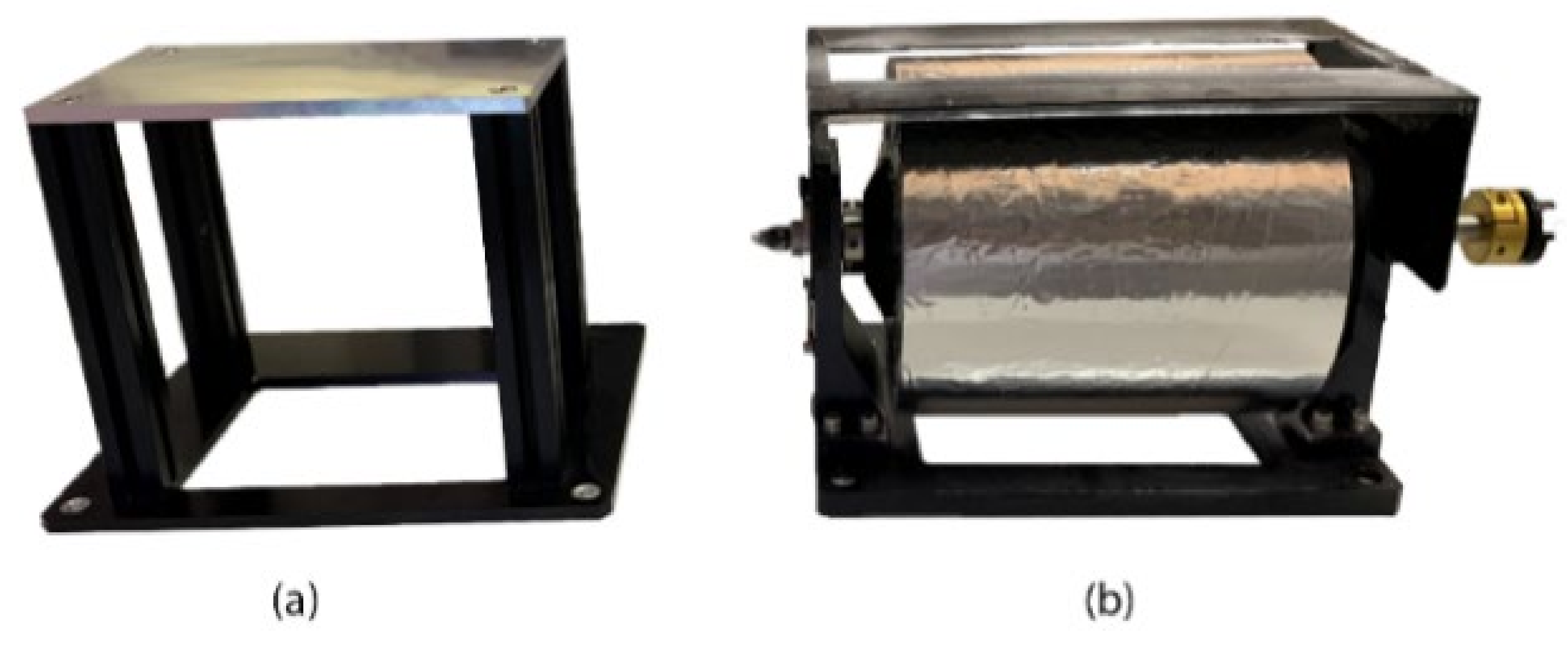
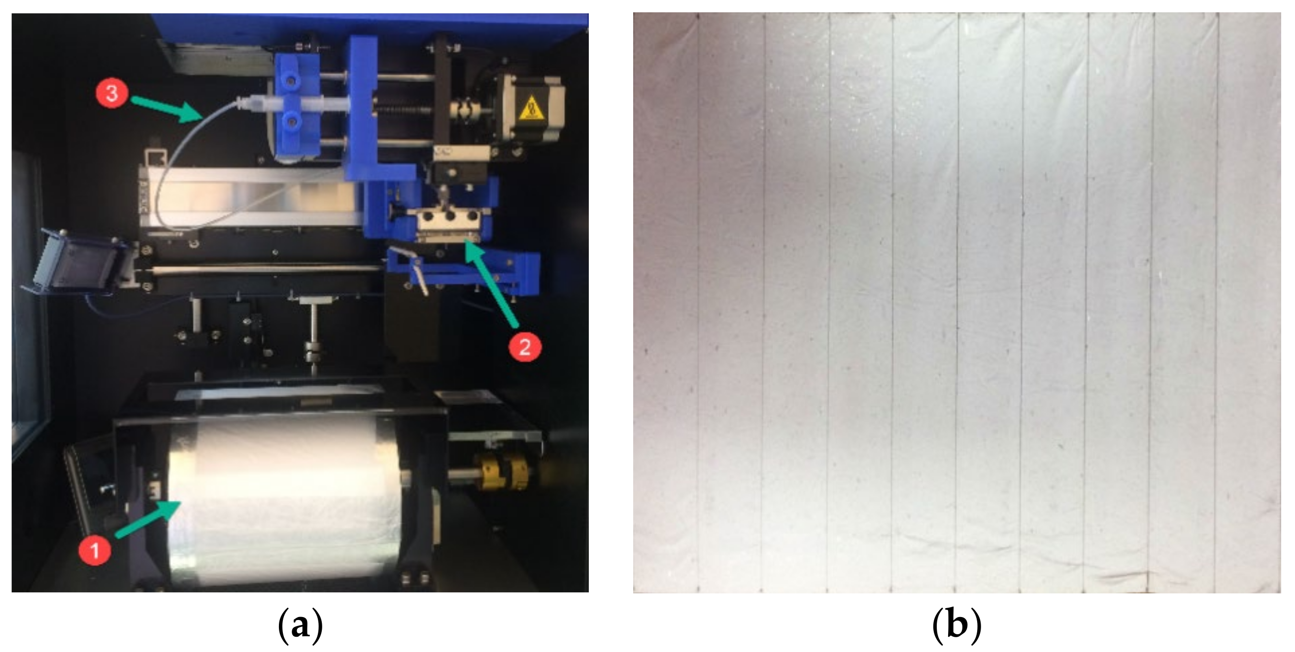
2.2. Fabrication of PVC Nanofibers
2.3. Methods
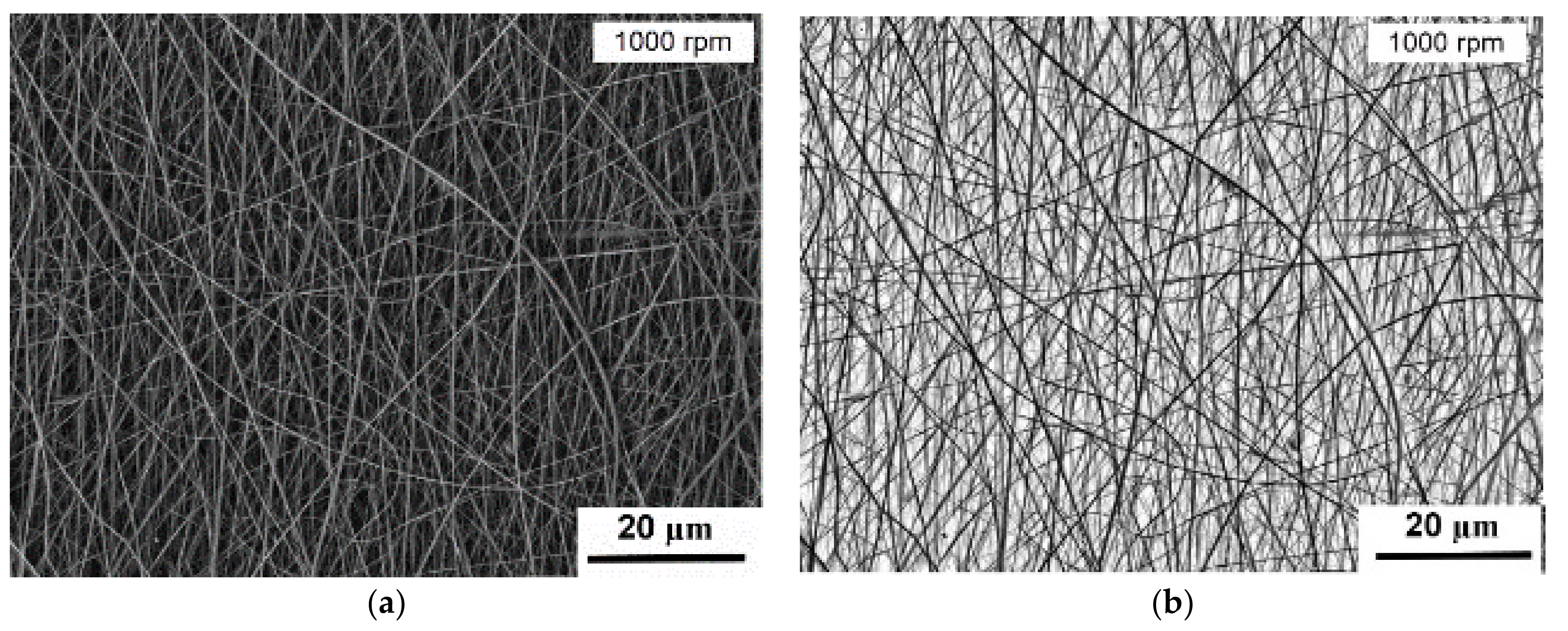
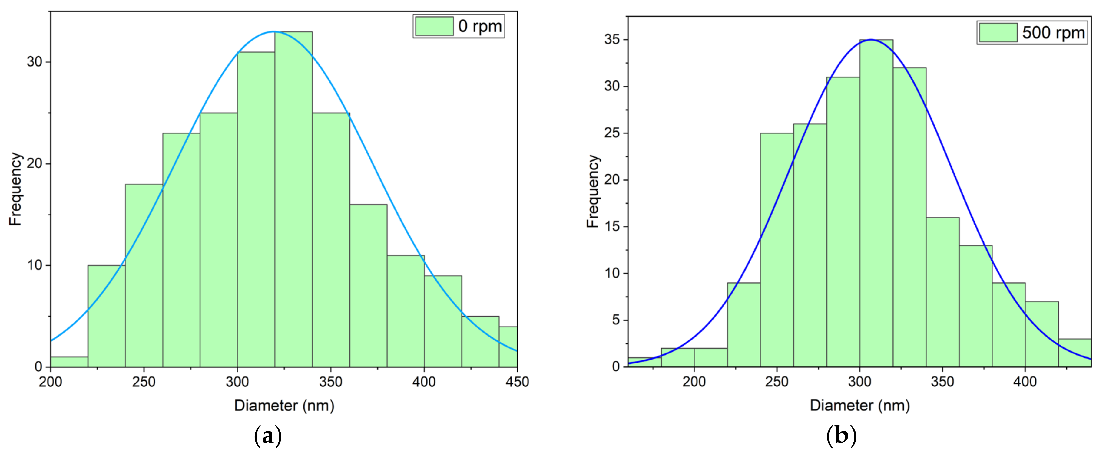
3. Results and Discussion
4. Conclusions
Author Contributions
Funding
Institutional Review Board Statement
Informed Consent Statement
Data Availability Statement
Conflicts of Interest
References
- Rahman, M.M. Introductory Chapter: Overview of Nanofibers. Nanofiber Res. Reach. New Heights 2016. [Google Scholar] [CrossRef]
- Dastidar, D.G.; Chakrabarti, G. Thermoresponsive Drug Delivery Systems, Characterization and Application. In Applications of Targeted Nano Drugs and Delivery Systems; Elsevier BV: Amsterdam, The Netherlands, 2019; pp. 133–155. [Google Scholar]
- Akduman, C.; Kumbasar, E.P.A. Electrospun Polyurethane Nanofibers. Asp. Polyurethanes 2017, 17–52. [Google Scholar] [CrossRef]
- Bhardwaj, N.; Kundu, S.C. Electrospinning: A Fascinating Fiber Fabrication Technique. Biotechnol. Adv. 2010, 28, 325–347. [Google Scholar] [CrossRef] [PubMed]
- Zhu, M.; Han, J.; Wang, F.; Shao, W.; Xiong, R.; Zhang, Q.; Pan, H.; Yang, Y.; Samal, S.K.; Zhang, F.; et al. Electrospun Nanofibers Membranes for Effective Air Filtration. Macromol. Mater. Eng. 2017, 302, 1600353. [Google Scholar] [CrossRef]
- Shabafrooz, V.; Mozafari, M.; Vashaee, D.; Tayebi, L. Electrospun Nanofibers: From Filtration Membranes to Highly Specialized Tissue Engineering Scaffolds. J. Nanosci. Nanotechnol. 2014, 14, 522–534. [Google Scholar] [CrossRef]
- Lv, D.; Wang, R.; Tang, G.; Mou, Z.; Lei, J.; Han, J.; De Smedt, S.C.; Xiong, R.; Huang, C. Ecofriendly Electrospun Membranes Loaded with Visible-Light-Responding Nanoparticles for Multifunctional Usages: Highly Efficient Air Filtration, Dye Scavenging, and Bactericidal Activity. ACS Appl. Mater. Interfaces 2019, 11, 12880–12889. [Google Scholar] [CrossRef]
- Zhu, M.; Xiong, R.; Huang, C. Bio-Based and Photocrosslinked Electrospun Antibacterial Nanofibrous Membranes for Air Filtration. Carbohydr. Polym. 2019, 205, 55–62. [Google Scholar] [CrossRef]
- Ma, W.; Li, Y.; Zhang, M.; Gao, S.; Cui, J.; Huang, C.; Fu, G. Biomimetic Durable Multifunctional Self-Cleaning Nanofibrous Membrane with Outstanding Oil/Water Separation, Photodegradation of Organic Contaminants, and Antibacterial Performances. ACS Appl. Mater. Interfaces 2020, 12, 34999–35010. [Google Scholar] [CrossRef]
- Cui, J.; Li, F.; Wang, Y.; Zhang, Q.; Ma, W.; Huang, C. Electrospun Nanofiber Membranes for Wastewater Treatment Applications. Sep. Purif. Technol. 2020, 250, 117116. [Google Scholar] [CrossRef]
- Zhang, M.; Ma, W.; Cui, J.; Wu, S.; Han, J.; Zou, Y.; Huang, C. Hydrothermal synthesized UV- Resistance and Transparent Coating Composited Superoloephilic Electrospun Membrane for High Efficiency Oily Wastewater Treatment. J. Hazard. Mater. 2020, 383, 121152. [Google Scholar] [CrossRef] [PubMed]
- Xu, C.; Inai, R.; Kotaki, M.; Ramakrishna, S. Electrospun Nanofiber Fabrication as Synthetic Extracellular Matrix and Its Potential for Vascular Tissue Engineering. Tissue Eng. 2004, 10, 1160–1168. [Google Scholar] [CrossRef] [PubMed]
- Nagarajan, S.; Belaid, H.; Pochat-Bohatier, C.; Teyssier, C.; Iatsunskyi, I.; Coy, E.; Balme, S.; Cornu, D.; Miele, P.; Kalkura, N.S.; et al. Design of Boron Nitride/Gelatin Electrospun Nanofibers for Bone Tissue Engineering. ACS Appl. Mater. Interfaces 2017, 9, 33695–33706. [Google Scholar] [CrossRef] [PubMed]
- Wei, Q.; Wei, A. Functional Nanofibers for Drug Delivery Applications. Funct. Nanofibers Appl. 2012, 153–170. [Google Scholar] [CrossRef]
- Gao, S.; Tang, G.; Hua, D.; Xiong, R.; Han, J.; Jiang, S.; Zhang, Q.; Huang, C. Stimuli-Responsive Bio-Based Polymeric Systems and Their Applications. J. Mater. Chem. B 2019, 7, 709–729. [Google Scholar] [CrossRef] [PubMed]
- Hua, D.; Liu, Z.; Wang, F.; Gao, B.; Chen, F.; Zhang, Q.; Xiong, R.; Han, J.; Samal, S.K.; De Smedt, S.C.; et al. pH Responsive Polyurethane (Core) and Cellulose Acetate Phthalate (Shell) Electrospun Fibers for Intravaginal Drug Delivery. Carbohydr. Polym. 2016, 151, 1240–1244. [Google Scholar] [CrossRef]
- Jiang, S.; Chen, Y.; Duan, G.; Mei, C.; Greiner, A.; Agarwal, S. Electrospun Nanofiber Reinforced Composites: A Review. Polym. Chem. 2018, 9, 2685–2720. [Google Scholar] [CrossRef]
- Ding, B.; Wang, M.; Wang, X.; Yu, J.; Sun, G. Electrospun Nanomaterials for Ultrasensitive Sensors. Mater. Today 2010, 13, 16–27. [Google Scholar] [CrossRef]
- Myndrul, V.; Coy, E.; Bechelany, M.; Iatsunskyi, I. Photoluminescence Label-Free Immunosensor for the Detection of Aflatoxin B1 Using Polyacrylonitrile/Zinc Oxide Nanofibers. Mater. Sci. Eng. C 2021, 118, 111401. [Google Scholar] [CrossRef]
- Yao, J.; Bastiaansen, C.W.; Peijs, T. High Strength and High Modulus Electrospun Nanofibers. Fibers 2014, 2, 158–186. [Google Scholar] [CrossRef]
- Linh, N.T.B.; Lee, B.-T. Electrospinning of Polyvinyl Alcohol/Gelatin Nanofiber Composites and Cross-Linking for Bone Tissue Engineering Application. J. Biomater. Appl. 2012, 27, 255–266. [Google Scholar] [CrossRef]
- El-Messiry, M.; Fadel, N. The Tensile Properties of Electrospun Poly Vinyl Chloride and Cellulose Acetate (PVC/CA) Bi-Component Polymers Nanofibers. Alex. Eng. J. 2019, 58, 885–890. [Google Scholar] [CrossRef]
- Huang, L.; Arena, J.T.; Manickam, S.S.; Jiang, X.; Willis, B.G.; McCutcheon, J.R. Improved Mechanical Properties and Hydrophilicity of Electrospun Nanofiber Membranes for Filtration Applications by Dopamine Modification. J. Membr. Sci. 2014, 460, 241–249. [Google Scholar] [CrossRef]
- Huang, L.; Manickam, S.S.; McCutcheon, J.R. Increasing Strength of Electrospun Nanofiber Membranes for Water Filtration Using Solvent Vapor. J. Membr. Sci. 2013, 436, 213–220. [Google Scholar] [CrossRef]
- Guibo, Y.; Qing, Z.; Yahong, Z.; Yin, Y.; Yumin, Y. The Electrospun Polyamide 6 Nanofiber Membranes Used as High Efficiency Filter Materials: Filtration Potential, Thermal Treatment, and Their Continuous Production. J. Appl. Polym. Sci. 2013, 128, 1061–1069. [Google Scholar] [CrossRef]
- Yu, L.; Shao, Z.; Xu, L.; Wang, M. High Throughput Preparation of Aligned Nanofibers Using an Improved Bubble-Electrospinning. Polym. 2017, 9, 658. [Google Scholar] [CrossRef] [PubMed]
- Bazrafshan, Z.; Stylios, G.K. Custom-Built Electrostatics and Supplementary Bonding in the Design of Reinforced Collagen-g-P(methyl methacrylate-co-ethyl acrylate)/Nylon 66 Core-Shell Fibers. J. Mech. Behav. Biomed. Mater. 2018, 87, 19–29. [Google Scholar] [CrossRef] [PubMed]
- Arras, M.M.L.; Grasl, C.; Bergmeister, H.; Schima, H. Electrospinning of Aligned Fibers with Adjustable Orientation Using Auxiliary Electrodes. Sci. Technol. Adv. Mater. 2012, 13, 35008. [Google Scholar] [CrossRef] [PubMed]
- Xu, C.; Inai, R.; Kotaki, M.; Ramakrishna, S. Aligned Biodegradable Nanofibrous Structure: A Potential Scaffold for Blood Vessel Engineering. Biomaterials 2004, 25, 877–886. [Google Scholar] [CrossRef]
- Baji, A.; Mai, Y.-W.; Wong, S.-C.; Abtahi, M.; Chen, P. Electrospinning of Polymer Nanofibers: Effects on Oriented Morphology, Structures and Tensile Properties. Compos. Sci. Technol. 2010, 70, 703–718. [Google Scholar] [CrossRef]
- Zhu, H.; Qiu, S.; Jiang, W.; Wu, D.; Zhang, C. Evaluation of Electrospun Polyvinyl Chloride/Polystyrene Fibers As Sorbent Materials for Oil Spill Cleanup. Environ. Sci. Technol. 2011, 45, 4527–4531. [Google Scholar] [CrossRef]
- Alarifi, I.M.; Alharbi, A.R.; Khan, M.; Khan, W.S.; Usta, A.; Asmatulu, R. Water Treatment using Electrospun PVC/PVP Nanofibers as Filter Medium. Int. J. Mater. Sci. Res. 2018, 2, 43–49. [Google Scholar] [CrossRef][Green Version]
- Es-saheb, M.; Elzatahry, A.A.; Sherif, E.S.M.; Alkaraki, A.S.; Kenawy, E.R. A Novel Electrospinning Application for Polyvinyl Chloride Nanofiber Coating Deposition as a Corrosion Inhibitor for Aluminum, Steel, and Brass in Chloride Solutions. Int. J. Electrochem. Sci. 2012, 7, 5962–5976. [Google Scholar]
- Nitti, P.; Gallo, N.; Natta, L.; Scalera, F.; Palazzo, B.; Sannino, A.; Gervaso, F. Influence of Nanofiber Orientation on Morphological and Mechanical Properties of Electrospun Chitosan Mats. J. Healthc. Eng. 2018, 2018, 1–12. [Google Scholar] [CrossRef]
- Engel, A.B.; Cherifi, A.; Bechelany, M.; Tingry, S.; Cornu, D. Control of Spatial Organization of Electrospun Fibers in a Carbon Felt for Enhanced Bioelectrode Performance. Chem. Plus Chem. 2015, 80, 440. [Google Scholar] [CrossRef]
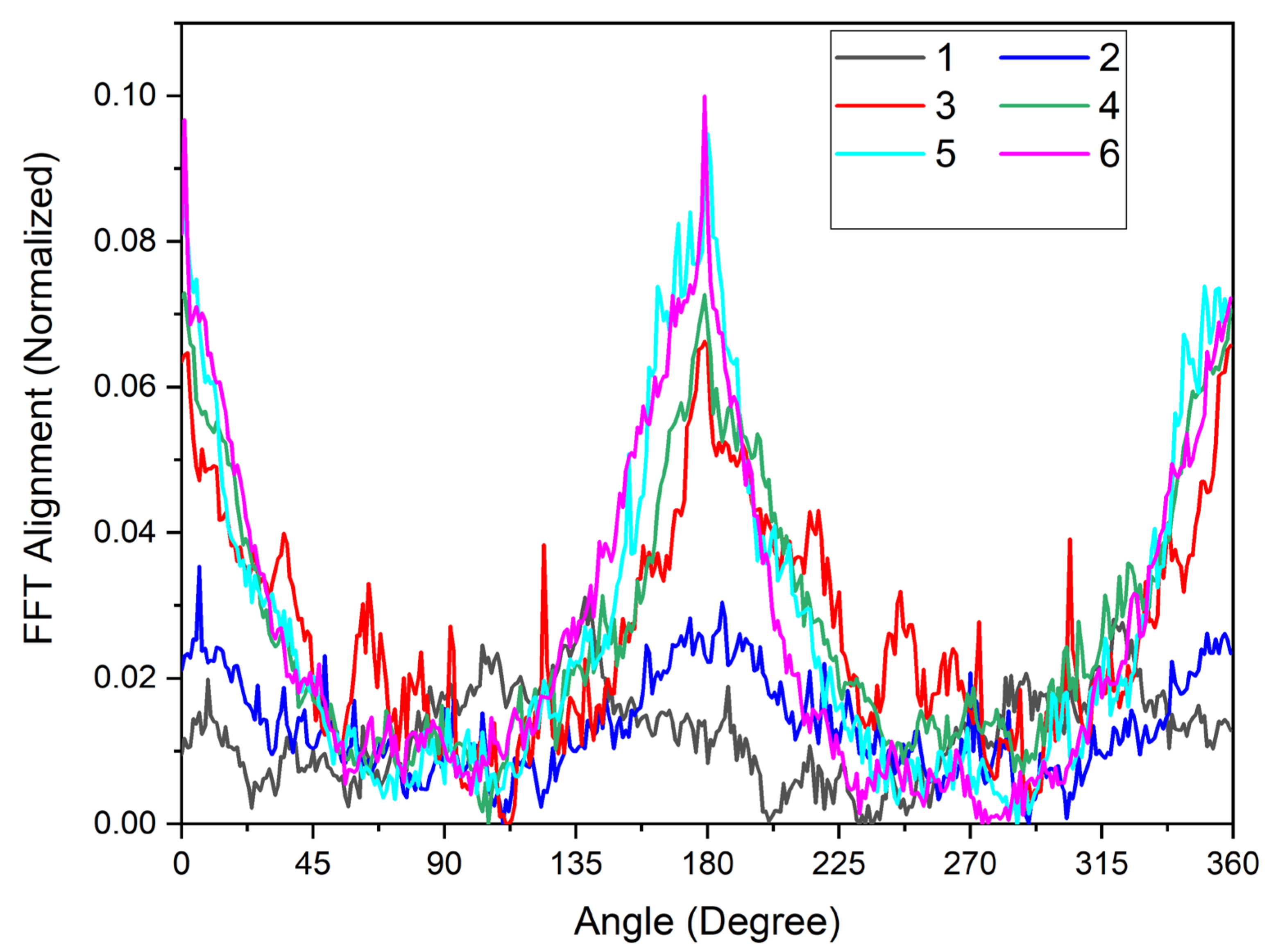
- Taylor, S.E.; Cao, T.; Talauliker, P.M.; Lifshitz, J. Objective Morphological Quantification of Microscopic Images Using a Fast Fourier Transform (FFT) Analysis. Curr. Protoc. Essent. Lab. Tech. 2013, 7, 1–9. [Google Scholar] [CrossRef] [PubMed]
- International Organization for Standardization. Plastics—Determination of Tensile Properties—Part. 3: Test. Conditions for Films and Sheets; British Standard: London, UK, 1995; Volume 3. [Google Scholar]
- Ayres, C.E.; Jha, B.S.; Meredith, H.; Bowman, J.R.; Bowlin, G.L.; Henderson, S.; Simpson, D.G. Measuring Fiber Alignment in Electrospun Scaffolds: A User’s Guide to the 2d Fast Fourier Transform Approach. J. Biomater. Sci. Polym. Ed. 2008, 19, 603–621. [Google Scholar] [CrossRef]
- Carrizales, C.; Pelfrey, S.; Rincon, R.; Eubanks, T.M.; Kuang, A.; McClure, M.J.; Bowlin, G.L.; Macossay, J. Thermal and Mechanical Properties of Electrospun PMMA, PVC, Nylon 6, and Nylon 6,6. Polym. Adv. Technol. 2008, 19, 124–130. [Google Scholar] [CrossRef]
- Li, W.-J.; Mauck, R.L.; Cooper, J.A.; Yuan, X.; Tuan, R.S. Engineering Controllable Anisotropy in Electrospun Biodegradable Nanofibrous Scaffolds for Musculoskeletal Tissue Engineering. J. Biomech. 2007, 40, 1686–1693. [Google Scholar] [CrossRef]
- Kim, G.H. Electrospun PCL Nanofibers with Anisotropic Mechanical Properties as a Biomedical Scaffold. Biomed. Mater. 2008, 3, 025010. [Google Scholar] [CrossRef]
- Wong, S.-C.; Baji, A.; Leng, S. Effect of Fiber Diameter on Tensile Properties of Electrospun Poly (ɛ-caprolactone). Polymers 2008, 49, 4713–4722. [Google Scholar] [CrossRef]
- Arinstein, A.; Burman, M.; Gendelman, O.; Zussman, E. Effect of Supramolecular Structure on Polymer Nanofibre Elasticity. Nat. Nanotechnol. 2007, 2, 59–62. [Google Scholar] [CrossRef] [PubMed]
- Chew, S.Y.; Hufnagel, T.C.; Lim, C.T.; Leong, K.W. Mechanical Properties of Single Electrospun Drug-Encapsulated Nanofibres. Nanotechnology 2006, 17, 3880–3891. [Google Scholar] [CrossRef] [PubMed]
- Gu, S.-Y.; Wu, Q.-L.; Ren, J.; Vancso, G. Mechanical Properties of a Single Electrospun Fiber and Its Structures. Macromol. Rapid Commun. 2005, 26, 716–720. [Google Scholar] [CrossRef]
- Wang, H.; Chang, T.; Li, X.; Zhang, W.; Hu, Z.; Jonas, A.M. Scaled Down Glass Transition Temperature in Confined Polymer Nanofibers. Nanoscale 2016, 8, 14950–14955. [Google Scholar] [CrossRef] [PubMed]


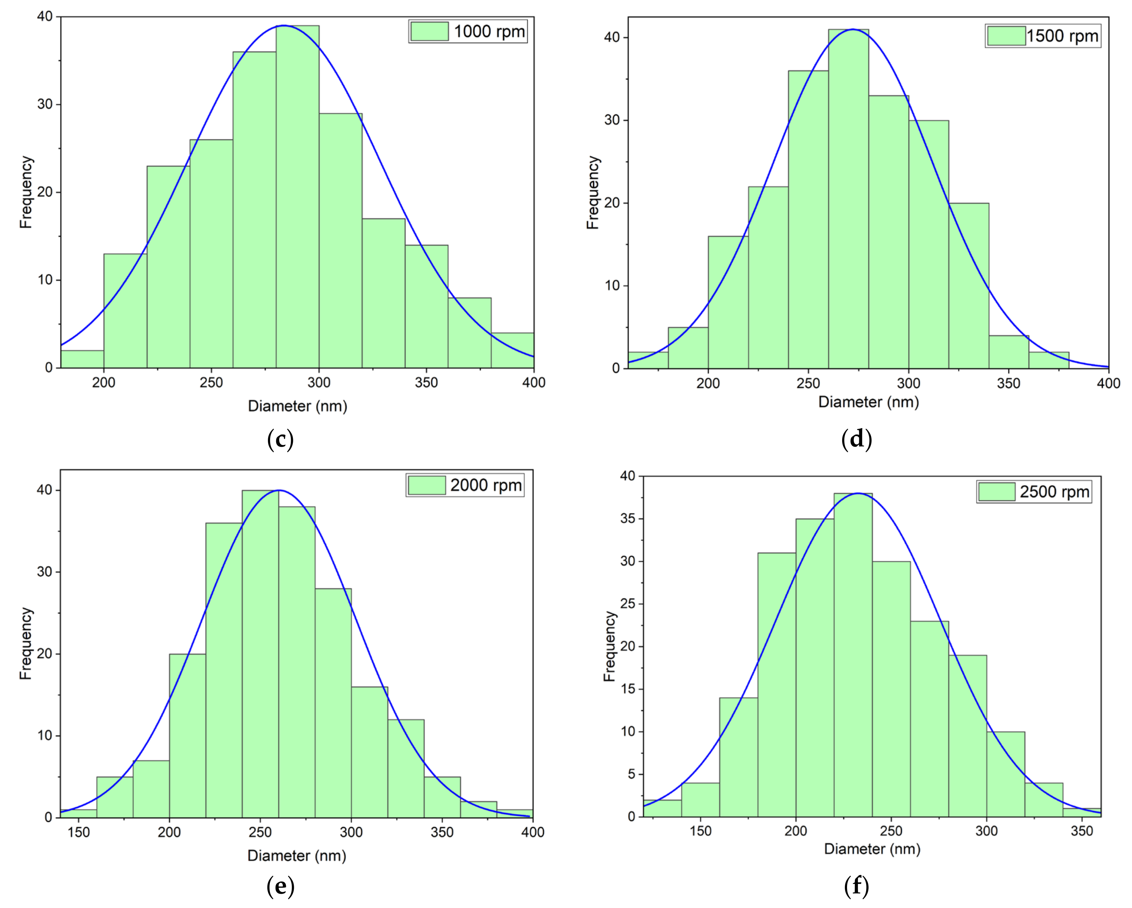
| Rotation Speed, rpm | 0 (Flat Plate Collector) | 500 | 1000 | 1500 | 2000 | 2500 |
|---|---|---|---|---|---|---|
| Mean nanofiber diameter, nm | 313 | 302 | 280 | 272 | 256 | 229 |
| Standard deviation (σ), nm | 52 | 46 | 43 | 47 | 39 | 47 |
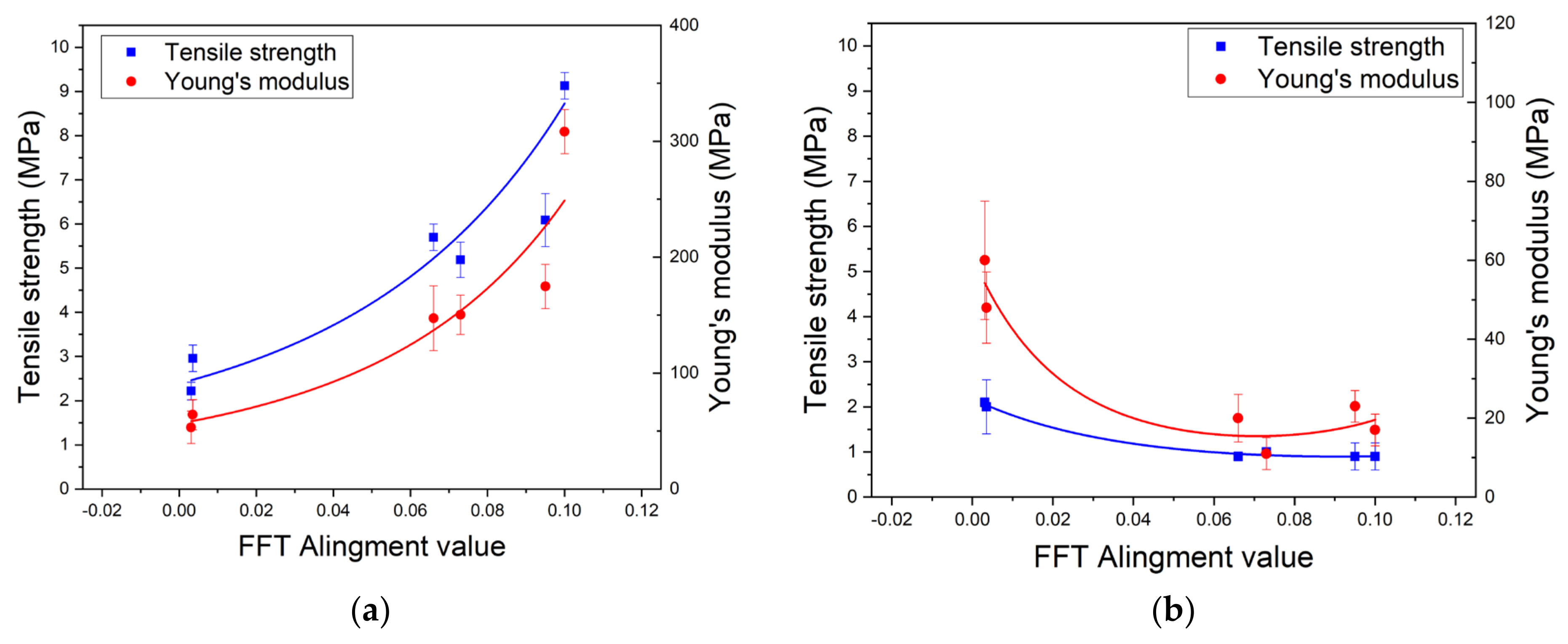
| Rotation Speed (rpm) | The Thickness of Nanofiber Mats (µm) | Tensile Strength, σat break (MPa) | Young’s Modulus, E (MPa) | Elongation at Break, εat break (%) |
|---|---|---|---|---|
| 0 | 73 ± 10 | 2.2 ± 0.2 | 53 ± 14 | 26 ± 3 |
| 500 | 33 ± 3 | 3.0 ± 0.3 | 64 ± 13 | 31 ± 7 |
| 1000 | 33 ± 3 | 5.7 ± 0.3 | 147 ± 28 | 30 ± 4 |
| 1500 | 25 ± 2 | 5.2 ± 0.4 | 150 ± 17 | 28 ± 5 |
| 2000 | 31 ± 2 | 6.1 ± 0.6 | 175 ± 19 | 24 ± 7 |
| 2500 | 20 ± 2 | 9.1 ± 0.3 | 308 ± 19 | 30 ± 4 |
| Rotation Speed (rpm) | Tensile Strength, σat break (MPa) | Young’s Modulus, E (MPa) | Elongation at Break, εat break (%) |
|---|---|---|---|
| 0 | 2.1 ± 0.1 | 60 ± 15 | 63 ± 6 |
| 500 | 2.0 ± 0.6 | 48 ± 9 | 74 ± 8 |
| 1000 | 0.9 ± 0.1 | 20 ± 6 | 66 ± 8 |
| 1500 | 1.0 ± 0.1 | 11 ± 4 | 80 ± 16 |
| 2000 | 0.9 ± 0.3 | 23 ± 4 | 100 ± 8 |
| 2500 | 0.9 ± 0.3 | 17 ± 4 | 105 ± 10 |
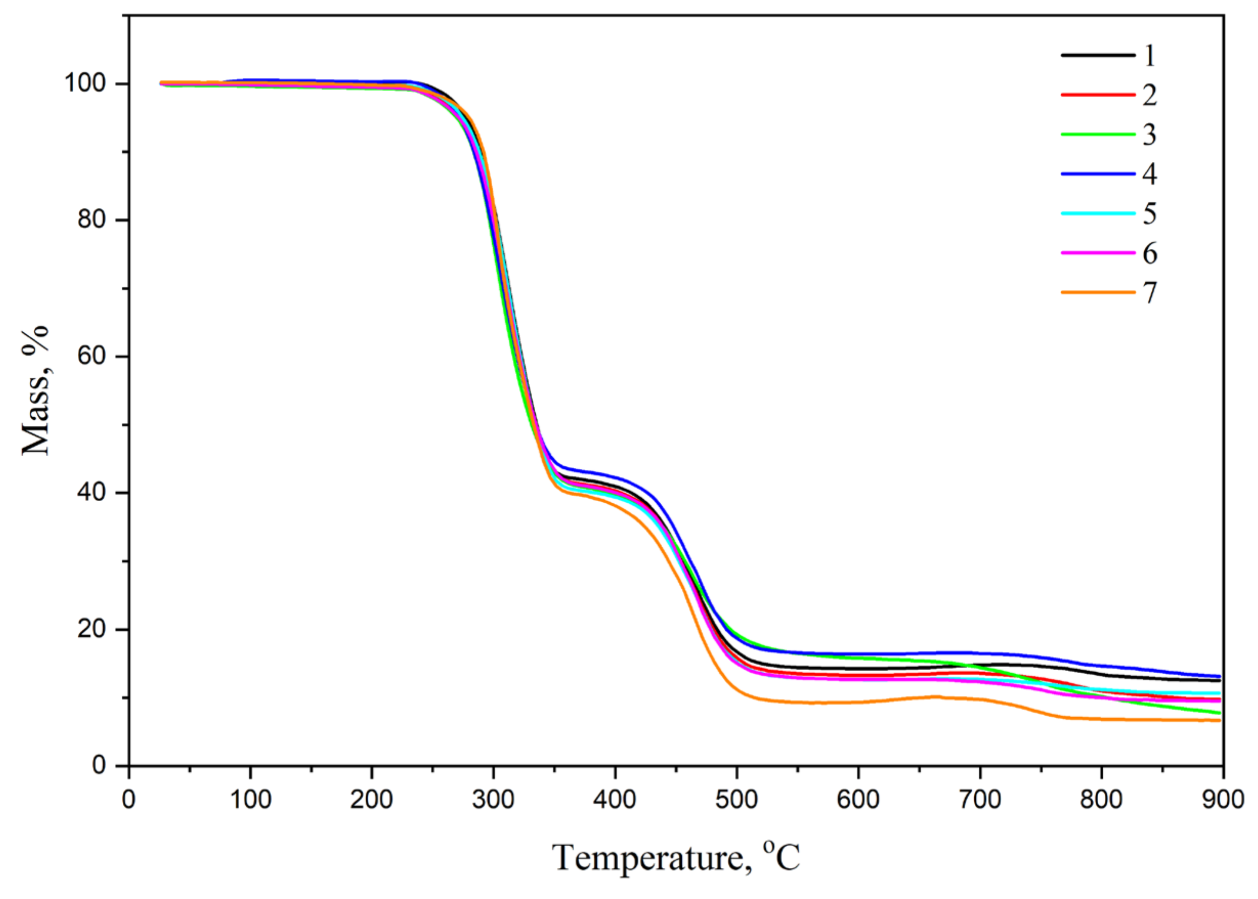
| Materials | PVC Powder | PVC Nanofiber Mats Obtained By Electrospinning At Different Rotational Speeds | |||||
|---|---|---|---|---|---|---|---|
| 0 (Flat Plate Collector) | 500 | 1000 | 1500 | 2000 | 2500 | ||
| The glass transition temperature (Tg), °C | 83.2 | 77.9 | 77.5 | 77.9 | 76.8 | 77.4 | 77.5 |
Publisher’s Note: MDPI stays neutral with regard to jurisdictional claims in published maps and institutional affiliations. |
© 2021 by the authors. Licensee MDPI, Basel, Switzerland. This article is an open access article distributed under the terms and conditions of the Creative Commons Attribution (CC BY) license (http://creativecommons.org/licenses/by/4.0/).
Share and Cite
Pham Le, Q.; Uspenskaya, M.V.; Olekhnovich, R.O.; Baranov, M.A. The Mechanical Properties of PVC Nanofiber Mats Obtained by Electrospinning. Fibers 2021, 9, 2. https://doi.org/10.3390/fib9010002
Pham Le Q, Uspenskaya MV, Olekhnovich RO, Baranov MA. The Mechanical Properties of PVC Nanofiber Mats Obtained by Electrospinning. Fibers. 2021; 9(1):2. https://doi.org/10.3390/fib9010002
Chicago/Turabian StylePham Le, Quoc, Mayya V. Uspenskaya, Roman O. Olekhnovich, and Mikhail A. Baranov. 2021. "The Mechanical Properties of PVC Nanofiber Mats Obtained by Electrospinning" Fibers 9, no. 1: 2. https://doi.org/10.3390/fib9010002
APA StylePham Le, Q., Uspenskaya, M. V., Olekhnovich, R. O., & Baranov, M. A. (2021). The Mechanical Properties of PVC Nanofiber Mats Obtained by Electrospinning. Fibers, 9(1), 2. https://doi.org/10.3390/fib9010002