Abstract
Two of the main advantages of segmental construction are economics, as well as the rapid construction technique. One of the forms of segmental construction, for structural elements, is the segmental beams that built-in short sections, which referred to segments. This research aims to exhibit a new technique for the fabrication of short-span segmental beams from wedge-shaped concrete segments and carbon fiber reinforced polymers (CFRP) in laminate form. The experimental campaign included eight short-span segmental beams. In this study, two selected parameters were considered. These parameters are; the number of layers of CFRP laminates and the adhesive material that used to bond segments to each other, forming short-span segmental beams. The test results showed that for segmental beams reinforced by 2-layer of CFRP laminates, undergoes less deflection and sustained considerable ultimate loading value of 38.4%–104% than beams reinforced by 1-layer. Moreover, the test of segmental beams fabricated by adhering to the concrete segments with epoxy resin exhibited an increase in ultimate loading by 16%–65% than beams constructed using cementitious adhesive for bonding the wedge-shaped segments. Theoretically, segmental beams were analyzed by the American Concrete Institute (ACI) 440.2R-17 procedure with slight modifications. The analysis gave an overestimation of flexural strength for segmental beams when compared with experimental outcomes.
1. Introduction
Segmental beams are generally fabricated in two methods according to either the structural application or their purposes. The first method is by casting concrete in-situ in individual molds, and the second one is by using precast prestressed concrete segments. Segmental construction by precast units has numerous features. In segmental construction, the quality of concrete is ensured as well as less working loads during construction phases in the site can be achieved, the speed of construction can be increased, and environmental effects can be alleviated [1]. Large scale segmental beams used for the construction of bridges overall the world. In practice, segmental beams may be straight or curved aligned, and they are fast, flexible, high quality, and economical construction techniques. The type of interface joint between individual segments, quality of joints, and mechanical interlock between segments will affect the behavioral performance of segmental bridges [2,3].
The utilization of advanced composite materials (ACMs) in many engineering fields has been expanded since the last few decades. ACMs characterized by the perfect mechanical engineering properties such as the high tensile strength, low-densities, and resistance to fatigue loads [4,5,6,7]. ACMs are currently one of the extraordinarily proper and functional strengthening and reinforcement solutions for upgrading and repair structural elements. At the same time, with the advance development of construction, it is required to eliminate problems relating to environmental collaboration and bring materials durable and compatible with the substrate concrete [8]. Flexural members like reinforced concrete beams are effectively upgraded, strengthened, and repaired by externally bonded carbon fiber reinforced polymers (EBR-CFRPs) composites [9]. Many causes lead to structural strengthening like deterioration, end of design life, change in the structural function, damage by mechanical actions, inadequate design, or design errors. Numerous researches, including practical applications, studied several methods for structural strengthening. One of the most efficient strengthening methods is by using EBR-CFRP laminates [10].
In the present study, the guidelines of the ACI 440.2R-17 [11] procedure was followed step-by-step in order to predict the ultimate loading-capacity of the short-span segmental beams. However, two assumptions adopted in order to make the ACI 440.2R-17 procedure applicable to the studied cases; (1) the segmental beams were considered being monolithic casted concrete members reinforced by CFRP laminates only at the soffit, and (2) the beams failed by the debonding of the CFRP laminates.
2. Research Significance
In this research, a new construction method for short-span segmental beams has been developed. Employment of CFRP laminates as an externally bonded flexural reinforcement and wedge-shaped unreinforced concrete blocks for manufacturing eight short-span segmental beams. Furthermore, the procedure of ACI 440.2R-17 was modified to be applicable for segmental beams and hence predict the ultimate load-carrying capacity. Moreover, validate the analysis results of short-span segmental beams according to the modified procedure.
3. Experimental Program of the Current Study
3.1. Description of Test Specimens
In this campaign, eight short-span segmental beams were fabricated and tested. Each beam consisted of seven wedge-shaped concrete blocks and reinforced EBR-CFRP laminates type Sika CarboDur plates [12] bonded by epoxy resin type Sikadur-30 LP [13]. The invented beams were tested experimentally under 4-point bending up to failure. The beams have an overall span length of (0.9 m), (0.2 m) width and (0.08 m) thickness (excluding the thickness of the CFRP plate as well as the bonding epoxy resin). Specimens designation system and typical segmental beam layout are shown in Figure 1 and Figure 2, respectively.
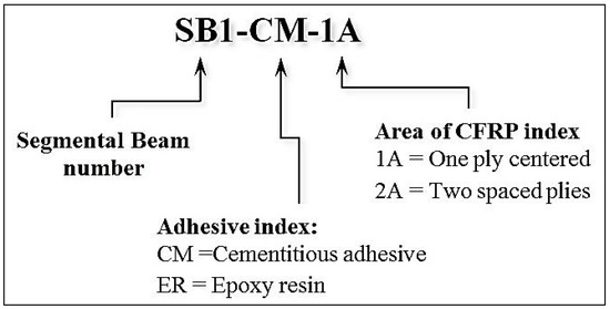
Figure 1.
Specimen designation system.
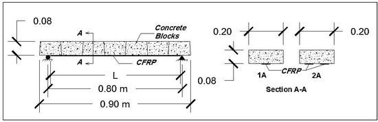
Figure 2.
Segmental beam layout.
3.2. Materials
3.2.1. Concrete
The concrete used for pre-casting the wedge-blocks was designed according to the British Standards (BS) mix design method [14,15]. The designed concrete has a specified compressive strength of 30 MPa at 28 days for standard cubes (150 × 150 × 150) mm3. Furthermore, the concrete mix proportion illustrated in Table 1. The molds used for casting wedge-shaped blocks were fabricated very accurately, using steel plates has (3 mm) thickness and (40 × 40 × 2) mm equal-legs steel angles. The steel molds and the casted plain concrete wedge-shape blocks are shown in Figure 3.

Table 1.
Mix proportions of designed concrete.
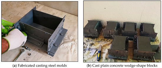
Figure 3.
Fabrication of plain concrete wedge-blocks.
1. Fresh Concrete Test
In order to confirm the mix design, the slump test performed for fresh concrete following ASTM C143-15a [16]. The recorded slump value for the fresh concrete was 80 mm.
2. Hardened Concrete Tests
The compressive strength, the splitting tensile strength, and the flexural strength tests conducted on standard concrete cubes, cylindrical, and prism specimens, respectively. These tests followed international regulations [17,18,19]. Experimental hardened concrete samples testing, as well as test results, were shown in Figure 4 and Table 2, respectively.
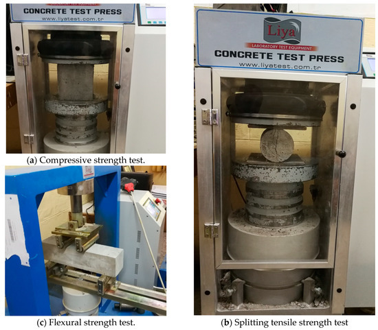
Figure 4.
Testing hardened concrete specimens.
Table 2.
Hardened concrete tests.
3.2.2. Carbon Fiber-Reinforced Polymer (CFRP) Laminates
Pultruded carbon fiber reinforced polymer (CFRP) laminates from Al-Umara’ Bureau for Construction Chemicals, Baghdad, Iraq type Sika CarboDur S514 [12] were used in the fabrication of the short-span segmental beams. The CFRP laminates adhered to the wedge-blocks through a two-component epoxy-based thixotropic adhesive type Sikadur®-30 LP [13]. Technical as well as mechanical properties of CFRP laminates and the epoxy resin were obtained from the manufacturer technical data sheet (TDS) and as described in Table 3.
Table 3.
Technical and mechanical properties of carbon fiber-reinforced polymer (CFRP) system.
3.3. Beams Fabrication
The experimental campaign comprises eight short-span segmental beams. As stated earlier, each beam consisted of seven individual wedge-shaped plain concrete segments. The beams are subdivided into four groups, four of the beams were made by adhering concrete blocks at the interfaces with cementitious adhesive type Cemfix W [20], and four were made by using epoxy resin type Sikadur-31 SBA S-02 [21] as concrete blocks adhesive. Additionally, four beams were constructed using a 1-layer of CFRP laminates at the center while the other four were fabricated using a 2-layer of CFRP laminates spaced 100mm. The CFRP laminates were bonded to the concrete blocks, at the bottom face, and along the beam span. The thickness of the CFRP laminates was 1.4 mm, and the total layup thickness was approximately 5.0 mm. All of the beams have typical cross-sectional dimensions as they were 200 mm in width and 80 mm depth. Those dimensions were selected to fulfill the width of walls or columns, which assumed that short-span segmental beams would install above. Technical, as well as mechanical properties for both types of adhering agents, were obtained from the manufacturer technical data sheet (TDS) and as described in Table 4.
Table 4.
Technical and mechanical properties of the used adhering materials in beams fabrications.
The tested beams were constructed after the curing of the wedge-blocks for 28 days. The blocks are arranged upside-down in between one and another; moreover, each concrete block adhered to the adjacent block at the interface by the two types, as mentioned above of adhering materials. The applied thickness of the cementitious adhesive type Cemfix W was 5 mm, while the applied thickness for the epoxy resin type Sikadur-31 SBA S-02 was 4 mm. The beams left for the setting of the adhesive for the proper time according to materials manufacturer instructions. Later on, locating the position of CFRP laminate for each segmental beam and a layer of 5 mm thick bonding epoxy was applied. The accomplishment of segmental beams construction by the installation of CFRP plates, which was pressed firmly using a special hand-roller as displayed in Figure 5. In order to obtain a wide range of data, two typical beams were fabricated for each of the four studied cases including the cross-sectional area EBR-CFRP laminate and the type of adhesive used for binding concrete blocks. The cross-sectional properties for tested short-span segmental beams are presented in Table 5.
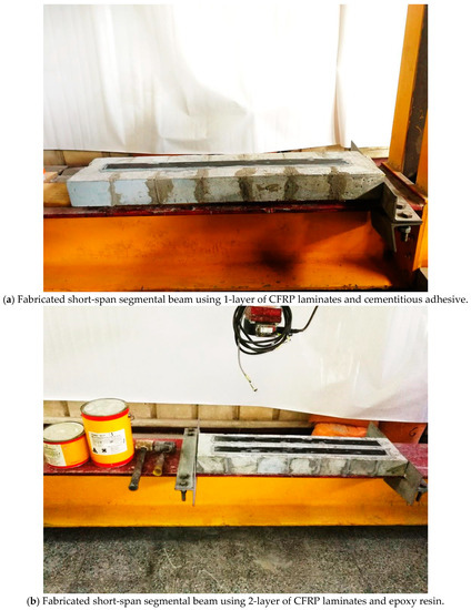
Figure 5.
Fabrication of segmental beams.
Table 5.
Properties of segmental beams.
3.4. Experimental Test Setup
Testing of segmental beams was done by subjecting all beams to four-point bending loads, as shown in Figure 6. The beams were positioned on two-simply support in the testing frame, which has an electrical hydraulic loading arm. A load cell with a capacity of 5 ton force was used to measure the loading value. Beams deflection under loading measured at both of quarter-span and mid-span employing two precise digital indicators ranged 0–25.4 mm and an accuracy of 0.01 mm. The tensile strain in the CFRP plates measured at both of the ends of the plate and mid-span through two, foil-type, strain gauges type BFLA-5-3-3-3LJC from Tokyo Measuring Laboratory (TML) with a gauge length of 5mm and transverse sensitivity of −0.1% according to the manufacturer. The compression strain in unreinforced concrete wedge-blocks also was measured at the extreme top fibers at beams mid-span by using strain gauges type PL-60-11-3L manufactured by TML with a gauge length of 60mm and transverse sensitivity of 0.6%. Campbell Scientific data-logger CR1000 was used to record strain values. Typical test arrangements of segmental beams testing-specimen are shown in Figure 7.
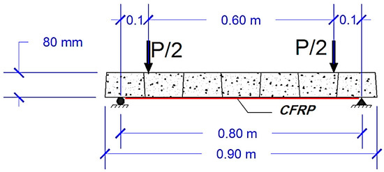
Figure 6.
The schematic diagram for the segmental beam subjected to loading.
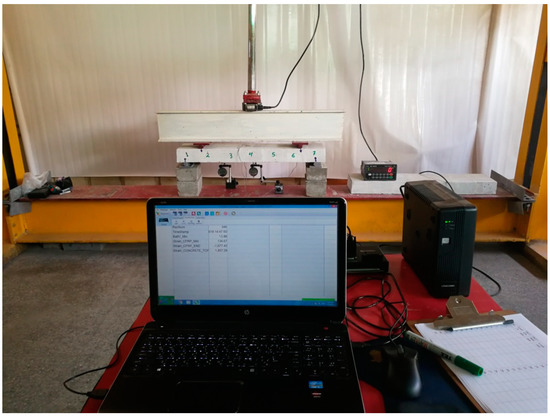
Figure 7.
Typical test arrangements of segmental beams specimen.
4. The Modified ACI 440.2R-17 Guide for Design and Construction Procedure of FRP Systems
The guidelines of ACI 440.2R-17 procedures were followed in the design of short-span segmental beams in order to predict the ultimate load-carrying capacity of those beams. However, two assumptions were adopted in order to make the ACI 440.2R-17 procedure applicable to the studied cases. The assumptions are:
- Due to the existence of the adhering materials at the interface between the adjacent concrete blocks, namely the epoxy and the cementitious adhesives, the segmental beams were considered being monolithic or one-unit casted concrete members.
- The segmental beams failed by the debonding of the CFRP laminates.
- Two short-span segmental beams were analyzed accordingly, and the ultimate loads were discussed.
5. Experimental Results and Discussion
5.1. Experimental Results
Ultimate load-carrying capacity and the corresponding quarter-span, as well as mid-span deflections, are presented in Table 6. Furthermore, the ultimate tensile and the compression strain results for the tested short-span segmental beams are presented in Table 7. The dispersion in the experimental data relative to the mean value evaluated by calculating the standard deviations for each two typical short-span segmental beams. The deviations in the ultimate failure loading result for each beam-group shown in column 4 in Table 6.
Table 6.
Test results of segmental beams.
Table 7.
Strains developed in segmental beams.
It is evident from the range of the standard deviation (0.88–1.58) that the deviations in the test results of each two typically fabricated and tested beams are not tangible, which indicates the accuracy of beams construction as well as the testing measurements. For further discussions for the data set of Table 6, it is clear that each typical beam (for example, SB1-CM-1A and SB2-CM-1A) sustain very close ultimate loads and exhibit almost similar displacements as well as strains. According to those as mentioned earlier, the results of each group of typical short-span beams are considered in the discussions.
5.2. Failure Modes of Short-Span Segmental Beams
Although all the beams were symmetrically loaded and had similar boundary conditions, the probability of symmetrical failure mode like monolithically-casted reinforced concrete beams is a few. This is because of the short-span segmental beams made from individual plain concrete segments. Short-span segmental beams specimens failed under loading in almost in a similar manner, as shown in Figure 8 and Figure 9 for beams SB1-CM-1A of group GI and SB7-ER-2A of group GIV, respectively. This behavior was observed regardless of the number of layers of the CFRP plates provided. However, the failure of the beams fabricated using epoxy resin, for adhering the concrete blocks, was slightly different from the beams that fabricated with the use of cementitious adhesive. A detail discussion is herein, for specimens of group GI the diagonal-shear crack propagates from the soffit of the beam (at the verge of CFRP-laminate in block seven) towards the closest blocks interface followed by debonding of cementitious adhesive. The mode of failure of group GIV is slightly different; the diagonal-shear crack propagates in an inclined angle from the soffit of the beam on the verge of EBR-laminate in block one crossing the interface with block two till the failure. The difference in the failure mode of the illustrated specimens is due to the strength of the adhering material used for beams fabrication. As the tensile strength of epoxy resin is considerably higher than the cementitious adhesive material used in specimens of group GI. It is essential to mention that no flexural cracks were observed for the tested specimens.
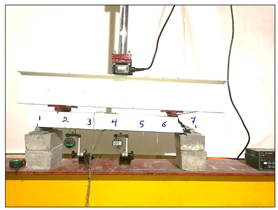
Figure 8.
The failure mode of beam SB1-CM-1A.
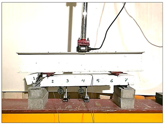
Figure 9.
The failure mode of Beam SB7-ER-2A.
5.3. Effect of the Adhering Materials on the Ultimate Loading of Short-Span Segmental Beams
The load-displacement curves for the selected, tested beams up to failure loads, at both quarter-span and mid-span, are shown in Figure 10 and Figure 11, respectively. Obviously, the segmental beam of group GIII exhibited a considerable ductile behavior up to the failure for both recorded displacements at the quarter-span, as well as the mid-span. This is mostly due to the response of the cementitious material used for binding the wedge-blocks, which allows this beam to exhibit elastic behavior than other beams.
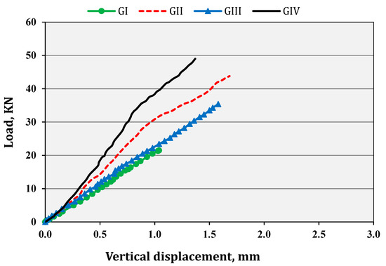
Figure 10.
Load vs. vertical displacement for the average of beam-groups at quarter-span.
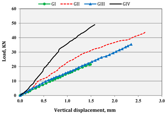
Figure 11.
Load vs. vertical displacement for the average of beam-groups at mid-span.
Considering short-span segmental beams of groups GI and GII, both of the beams reinforced by 1-layer of CFRP plates, but each beam was fabricated using different adhering material for bonding the wedge-concrete blocks at the contact interfaces. The former was fabricated using cementitious adhesive, while the latter was made using epoxy resin. Segmental beams of group GII exhibited a considerable increase in the ultimate loading, which was 65% more than group GI, which is mainly due to the inherent property of the epoxy resin. Similarly, comparing segmental beam groups GIII and GIV, both of the beam group have a 2-layer of CFRP plates, yet each one was fabricated utilizing different bonding material. The contribution of the used epoxy resin in beams of group GIV resulted in a slightly higher load-carrying capacity than beams of group GIII is about 16%. This limit increased in the loading capacity was due to the effect of the larger area of CFRP laminates in beams cross-section comparing with the beams reinforced by half the area of CFRP laminates.
5.4. Effect of Number of Layers of CFRP Laminates on the Ultimate Loading of Short-Span Segmental Beams
Segmental beams of groups GIII and GI were fabricated using the same cementitious adhesive, but the former has a 2-layer of CFRP laminate in the cross-section while the later have only 1-layer of CFRP laminate. Beams of group GIII withstand a very considerable loading of about 104% higher than beams of group GI, which is due to the extreme contribution of the area of CFRP reinforcement in the ultimate loading capacity. Furthermore, considering short-span segmental beams of groups GII and GIV, both were fabricated using the same epoxy resin for adhering the wedge-blocks. However, the later beam has a 2-layer of the CFRP plates in the cross-section while the former has only one 1-layer of CFRP plate. The beams in group GIV sustain enhanced ultimate loading of about 38.4% more than beams in group GII. The results were quite reasonable, as the effect of using a 2-layer of CFRP plates in the beam made by cementitious adhesive will undoubtedly be considerable when compared with beam constructed by using epoxy resin for the concrete block is adhering.
5.5. Distinguish Ultimate Strength of Beam SB7-ER-2A
Short-span segmental beams of group GIV sustains the most considerable loads up to failure among all tested specimens. The only explanation for this behavior is due to the dual-action resulted from both of the epoxy resin which bonds the wedge-blocks, as it has considerable tensile stress when compared with the cementitious adhesive, and the 2-layer of CFRP plates.
5.6. Strain in Short-Span Segmental Beams
The applied loading vs. tensile strain in the CFRP laminates at the mid-span and the end-span for tested specimens are shown in Figure 12 and Figure 13, respectively. From these curves, it is noticeable that the reinforcement of the beams of group GI strained higher than the other beams at the end-zone of CFRP laminates. Segmental beams of group GI were made by using; 1-layer of CFRP laminate and weak cementitious bonding material. The strain values for other specimens were almost the same at the end-zone of CFRP laminates.
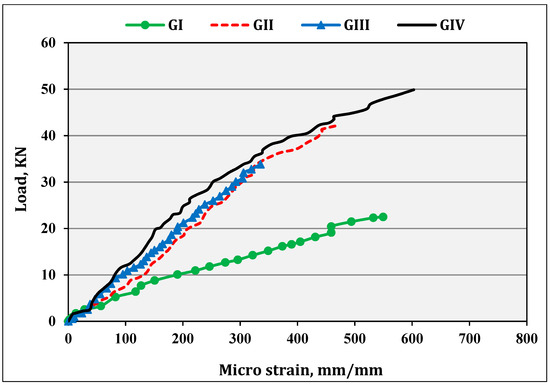
Figure 12.
Load vs. tensile strain in externally bonded carbon fiber reinforced polymer EBR-CFRP laminates at mid-span for an average of tested groups.
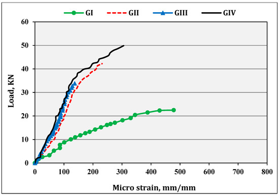
Figure 13.
Load vs. tensile strain in EBR-CFRP laminates at end-span for an average of tested groups.
Strains developed in the CFRP laminates at the end span of group GI was remarkably higher than the other beam groups GII, GIII, GIV by 230%, 97%, 156%, respectively. The strain results in the CFRP laminates of the segmental beams within-group GI was excluded from the analysis as it was not expected. Using a lower number (1-layer) of CFRP laminates and a relatively weak cementitious binder should reduce the final value of the tensile strains. Furthermore, the behavior of beams in group GI was anomalous than the segmental beams within other groups which may be due to an error that occurred during the test-setup or the data acquisition that was not discovered before testing.
An increase in the strain developed in the 2-layer of CFRP laminate of beams in group GIV was slightly higher by 23% than beams in group GIII while the increase was considerable when compared with beams of groups GII which was 72%. The number of layers of CFRP laminates and the type of adhesive material played an important role in the developed strains in the segmental beams. It is essential to state that no debonding of CFRP laminates observed for all tested short-span segmental beams.
Moreover, the developed strain in the wedge-blocks, at the extreme compression fibers of the beams was investigated at the mid-span of the beam specimens. In Figure 14, it was evident that segmental beams of group GIV withstand the greatest average loading value of 49.9 KN among all groups. Therefore, it was expected that the specimens in group GIV will exhibit higher compression strain and resisted the flexural bending considerably. However, beam specimens of groups GI, GII, and GIII behaved similar to segmental beams of GIV but exhibited less compression strain, about 42%, 13%, and 35%, respectively at failure loading.
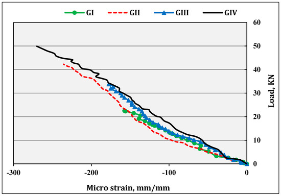
Figure 14.
Load vs. compression strain in concrete blocks at mid-span for an average of tested groups.
The hypothetical strain gradient, across the depth of the beam-groups (except for group GI), at mid-span and for different loading stages, is shown in Figure 15. The presented strain gradients, in the figure, as mentioned earlier, were for the recorded values at the extreme tension and compression fibers. It was highlighted that the depth of the compression zone decreased during loading progress for all specimens, likewise normal reinforced concrete beams. At the same time, the compression strains, and hence the stresses, increased in the concrete blocks, as the depth of the compression zone decreased. This behavior was unlike over reinforced traditional flexural members; the depth of the compression zone increased during loading progress. Even-though, the brittle failure mode of the tested specimens, was similar to over reinforced traditional flexural members [9,10].
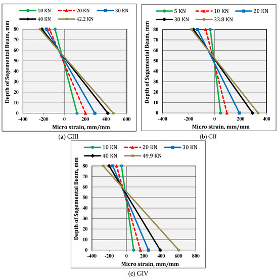
Figure 15.
Strain gradient across the depth for an average of each group of segmental beams.
6. Validation of the Modified Procedure of ACI 440.2R-2017 Guidelines
Short-span segmental beams were analyzed using the procedure of ACI 440.2R-2017, with slight modifications. This procedure was adopted in order to predict the load-carrying capacities for each beam following the assumptions in Section 4 of this research. The beams were designated by; SB-1A and SB-2A, according to the number of layers of CFRP plates and under similar experimental four-point bending loading, as well as the boundary conditions. The analysis predicted a nominal strength of 38.9 KN and 72.4 KN for SB-1A and SB-2A, respectively. Figure 16 described the ultimate loading, for all considered segmental beams, that have either 1-layer or 2-layer of CFRP-laminates. The analysis outcomes of the modified analysis procedure of ACI 440.2R-2017 was an upper-bound value when compared with the tested short-span segmental beams specimens.
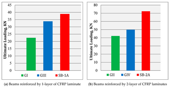
Figure 16.
Comparison of experimental and analysis results.
The analysis of beams SB-1A resulted in a conservative overestimation in strength by (81%) when compared with the physical model results of group GI. However, it was slightly higher than beams of group GII by 10% only. The modified procedure predicts an acceptable result when compared with the experimental results of group-specimen GII, which reflects the validity of the first assumption. The later beam was fabricated using epoxy resin for adhering concrete blocks. However, this assumption was not valid when comparing with SB1-CM-1A, which is made by using cementitious adhesive for bond the wedge-concrete blocks.
The analysis of beams SB-2A resulted in a conservative overestimation in strength by 65% and 48% when compared with the experimental results of group GIII and GIV, respectively. Therefore, the modified procedure predicts unacceptable results when compared with test results for the short-span beam specimens, regardless of the fabrication process were done using cementitious adhesive or epoxy resin for adhering the concrete blocks. That reflects the invalidity of the first assumption used in modifying the ACI 440.2R-2017 procedure.
The researcher did not observe the debonding of CFRP laminates, up to failure, during the tests of all the short-span segmental beams specimens. This also reflects the invalidity of the second assumption used in modifying the ACI 440.2R-2017 procedure.
7. Conclusions
Eight innovative short-span segmental beams were fabricated, using precast wedge-shaped concrete blocks and CFRP plates, and tested up to failure. Moreover, the segmental beams were analyzed employing the ACI 440.2R-2017 procedure with two presumptions. The following conclusions were developed, from the testing campaign, as well as the modified analysis procedure:
- The fabrication method of short-span segmental beams was found to be useful as the beams sustained considerable loading for the selected cross-sectional dimensions.
- The failure modes of the beams may reveal a disadvantage in the system. However, if the loading scheme changed, the failure mode may also be changed.
- The results displayed that beams assembled by epoxy resin adhesive (for segmental beam groups GII and GIV) sustained considerable loading, about 16%–65% than beams fabricated by cementitious adhesive (for segmental beam groups GI and GIII).
- Using the epoxy resin, for bonding precast concrete blocks, have further benefits like setting faster and assembling easier than beams assembled by cementitious adhesive.
- Reinforcing segmental beams by 2-layer of EBR-CFRP laminates significantly affects the beam′s ultimate strength, especially for beams assembled using cementitious adhesive. The mean ultimate load-carrying capacity is increased by 88% compared with segmental beams reinforced by 1-layer of CFRP laminates.
- In general, the assumptions used in modifying the ACI 440.2R-2017 procedure were invalid. Both of the assumptions were not enough to predict accurate and acceptable outcomes for the load-carrying capacity of short-span segmental beams. Furthermore, the failure modes of tested specimens were different from the assumed mode as no debonding of CFRP laminates observed.
8. Area of Future Studies
To summarize the recommendations for future work, the following points are highlighted:
- Investigation of the behavior of short-span segmental beams reinforced by CFRP laminates along the beam span to supports.
- Investigation of the behavior of short-span segmental beams reinforced by prestressed post-tension tendons.
- Conducting experimental tests on long-span segmental beams.
- Formulating numerical model for analyzing short-span segmental beams reinforced by CFRP laminates.
- Conducting experimental tests on short-span segmental beams manufactured from wedge-shape high-strength concrete segments.
- Investigate segmental beams fabricated from blocks with shear keys.
- Studying further assumption to the modified ACI 440.2R-2017 to obtain acceptable results.
Author Contributions
Conceptualization, A.A.A. and A.I.S.; methodology, A.A.A. and A.I.S.; validation, A.A.A. and A.I.S.; investigation, A.A.A.; resources, A.A.A.; data curation, A.A.A.; writing—original draft preparation, A.A.A.; writing—review and editing, A.A.A.; visualization, A.A.A. and A.I.S.; supervision, A.I.S. All authors have read and agreed to the published version of the manuscript.
Funding
This research received no external funding.
Acknowledgments
The authors would like to thank the lab staff at the Civil Engineering Department, College of Engineering, University of Baghdad, for their assistant.
Conflicts of Interest
The authors declare no conflict of interest.
References
- Li, G.; Yang, D.; Lei, Y. Combined shear and bending behavior of joints in precast concrete segmental beams with external tendons. J. Bridge Eng. 2013, 18, 1042–1052. [Google Scholar] [CrossRef]
- Saibabu, S.; Srinivas, V.; Sasmal, S.; Lakshmanan, N.; Iyer, N. Performance evaluation of dry and epoxy jointed segmental prestressed box girders under monotonic and cyclic loading. Constr. Build. Mater. 2013, 38, 931–940. [Google Scholar] [CrossRef]
- Saibabu, S.; Joshuva, R.; Kumar, K.; Lakshmikandhan, K.; Sivakumar, P. Finite element modelling of segmental model beam. Indian Concr. J. 2016, 90, 1–8. [Google Scholar]
- Pendhari, S.S.; Kant, T.; Desai, Y.M. Application of polymer composites in civil construction: A general review. Compos. Struct. 2007, 84, 114–124. [Google Scholar] [CrossRef]
- Abdulhameed, A.A.; Said, A.I. Experimental Investigation of the Behavior of Self-Form Segmental Concrete Masonry Arches. Fibers 2019, 7, 58. [Google Scholar] [CrossRef]
- Mohaisen, S.K.; Abdulhameed, A.A.; Kharnoob, M.M. Behavior of Reinforced Concrete Continuous Beams under Pure Torsion. J. Eng. 2016, 22, 1–15. [Google Scholar]
- Abdulhameed, A.A.; Said, A.I. Behaviour of Segmental Concrete Beams Reinforced by Pultruded CFRP Plates: An Experimental Study. J. Eng. 2019, 25, 62–79. [Google Scholar] [CrossRef][Green Version]
- Hanoon, A.N.; Abdulhameed, A.A.; Abdulhameed, H.A.; Mohaisen, S.K. Energy Absorption Evaluation of CFRP-Strengthened Two-Spans Reinforced Concrete Beams under Pure Torsion. Civ. Eng. J. 2019, 5, 2007–2018. [Google Scholar] [CrossRef]
- Codispoti, R.; Oliveira, D.; Olivito, R.; Lourenco, P.; Fangueiro, R. Mechanical performance of natural fiber-reinforced composites for the strengthening of masonry. Compos. Part B Eng. 2015, 77, 74–83. [Google Scholar] [CrossRef]
- Toutanji, H.; Zhao, L.; Zhang, Y. Flexural behavior of reinforced concrete beams externally strengthened with CFRP sheets bonded with an inorganic matrix. Eng. Struct. 2006, 28, 557–566. [Google Scholar] [CrossRef]
- American Concrete Institute. Guide for the Design Construction of Externally Bonded FRP Systems for Strengthening Concrete Structures (ACI 440.2R-2017); ACI: Farmington Hills, MI, USA, 2017. [Google Scholar]
- Sika Group. Available online: https://pak.sika.com/dms/getdocument.get/221d6d82-ec39-358c-b330-966a44f4b0ef/Sika%C2%AE%20CarboDur%C2%AE%20Plates.pdf (accessed on 19 July 2019).
- Sika Group. Available online: https://gcc.sika.com/dms/getdocument.get/2d67a8ed-ffe0-3a36-96cb-423ff70a1b14/2_Sikadur-30%20LP_PDS_GCC_(03-2017)_3_1.pdf (accessed on 19 July 2019).
- British Standards Institution. BS EN 206 Concrete-Specifications, Performance, Production, and Conformity; British Standards Institution: London, UK, 2013. [Google Scholar]
- British Standards Institution. BS EN 8500–1 Concrete—Complementary British Standard to BS EN 206 Part. 1: Method of Specifying and Guidance for the Specifier; British Standards Institution: London, UK, 2015. [Google Scholar]
- American Society for Testing and Materials. ASTM C143–15 Standard Test. Method for Slump of Hydraulic-Cement Concrete; American Society for Testing and Materials: West Conshohocken, PA, USA, 2010. [Google Scholar]
- British Standards Institution. BS EN 12390–3, Testing Hardened Concrete Part. 3: Compressive Strength of Test. Specimens; British Standards Institution: London, UK, 2011. [Google Scholar]
- American Society for Testing and Materials. ASTM C496/496M-17, Standard Test. Method for Splitting Tensile Strength of Cylindrical Concrete Specimens; American Society for Testing and Materials: West Conshohocken, PA, USA, 2011. [Google Scholar]
- American Society for Testing and Materials. ASTM C78–15a, Standard Test. Method for Flexural Strength of Concrete (Using Simple Beam with Third-Point Loading); American Society for Testing and Materials: West Conshohocken, PA, USA, 2015. [Google Scholar]
- Don Construction Products. Available online: http://dcp-int.in/iq/pages/en_prod1012/Cemfix%20W_TDS.pdf (accessed on 19 July 2019).
- Sika Group. Available online: http://www.epms-supplies.co.uk/admin/products/documents/Sika/Data/Sikadur%2031%20SBA%20S-02.%20PDS.pdf (accessed on 19 July 2019).


© 2020 by the authors. Licensee MDPI, Basel, Switzerland. This article is an open access article distributed under the terms and conditions of the Creative Commons Attribution (CC BY) license (http://creativecommons.org/licenses/by/4.0/).