Article

Improve in CO2 and CH4 Adsorption Capacity on Carbon Microfibers Synthesized by Electrospinning of PAN

by
Reyna Ojeda-López
1,2,*,
J. Marcos Esparza-Schulz
1,
Isaac J. Pérez-Hermosillo
1,
Armin Hernández-Gordillo
3 and
Armando Domínguez-Ortiz
1,*
1
Departamento de Química, Universidad Autónoma Metropolitana-Iztapalapa, 09340 CDMX, México
2
Departamento de Ingeniería Química y Bioquímica, Instituto Tecnológico de Oaxaca, 68030 Oaxaca de Juárez, México
3
División de Ciencias Ambientales, Instituto Potosino de Investigación Científica y Tecnológica (IPICyT), 78216 San Luis Potosí, México
*
Authors to whom correspondence should be addressed.
Fibers 2019, 7(10), 81; https://doi.org/10.3390/fib7100081
Submission received: 23 August 2019 / Revised: 13 September 2019 / Accepted: 18 September 2019 / Published: 21 September 2019

Abstract

:
Carbon microfibers (CMF) has been used as an adsorbent material for CO2 and CH4 capture. The gas adsorption capacity depends on the chemical and morphological structure of CMF. The CMF physicochemical properties change according to the applied stabilization and carbonization temperatures. With the aim of studying the effect of stabilization temperature on the structural properties of the carbon microfibers and their CO2 and CH4 adsorption capacity, four different stabilization temperatures (250, 270, 280, and 300 °C) were explored, maintaining a constant carbonization temperature (900 °C). In materials stabilized at 250 and 270 °C, the cyclization was incomplete, in that, the nitrile groups (triple-bond structure, e.g., C≡N) were not converted to a double-bond structure (e.g., C=N), to form a six-membered cyclic pyridine ring, as a consequence the material stabilized at 300 °C resulting in fragile microfibers; therefore, the most appropriate stabilization temperature was 280 °C. Finally, to corroborate that the specific surface area (microporosity) is not the determining factor that influences the adsorption capacity of the materials, carbonization of polyacrylonitrile microfibers (PANMFs) at five different temperatures (600, 700, 800, 900, and 1000 °C) is carried, maintaining a constant temperature of 280 °C for the stabilization process. As a result, the CMF chemical composition directly affects the CO2 and CH4 adsorption capacity, even more directly than the specific surface area. Thus, the chemical variety can be useful to develop carbon microfibers with a high adsorption capacity and selectivity in materials with a low specific surface area. The amount adsorbed at 25 °C and 1.0 bar oscillate between 2.0 and 2.9 mmol/g adsorbent for CO2 and between 0.8 and 2.0 mmol/g adsorbent for CH4, depending on the calcination treatment applicated; these values are comparable with other material adsorbents of greenhouse gases.

Graphical Abstract

1. Introduction

In the last few years, carbon dioxide (CO2) and methane (CH4) emissions have become the most important greenhouse gases with the largest impact on climate change [1]. As a result, several researchers have focused on the development of efficient materials for CO2 and CH4 capture. A viable methodology for greenhouse gases capture is adsorption at mild conditions, because the adsorbents materials are easily modifiable, reusable, and adsorption is a low energetic process [2,3,4]. Some materials have been tested as adsorbents for greenhouse gases, for example, zeolites [5,6], alumina [7], mesoporous silica [8,9,10,11], and porous carbons (graphite, carbon nanotubes, and carbon fibers) [3,12,13,14,15]. Particularly, ideal CO2 adsorbents should comply with the following characteristics: a high specific surface area, homogenous micro- and mesopores, and many active sites on the surfaces, such as amine functional groups and basic metal oxide [13]. In contrast, methane exhibits weak interaction with most materials, one of the reasons is due to the absence of a polar momentum [16,17]. Carbon microfibers (CMF) satisfy the requirements, due to their adequate physical and chemical properties such as large specific surface area, high electronic conductivity, active nitrogen sites, and remarkable mechanical and thermal resistance [12,18,19].
In order to improve the adsorption efficiency of CMF, it is necessary to determine which physicochemical properties are the most important to achieve this goal, and how the heat treatments in the synthesis influence them. Usually, carbon fibers are synthesized by electrospinning because of its simplicity, low-cost, and industrially scalability [20,21,22,23,24]. The electrospinning process consists of the use of polymer solutions subjected to a high voltage difference to force the generation of polymer fibers [25,26,27]. The most used polymer for this process is polyacrylonitrile (PAN), mainly due to its high thermal deformation resistance and carbon yield [8,9,12,28]. After the formation of PAN microfibers (PANMFs), a thermal process is necessary to obtain CMF, which involves two heat sequential treatments: (i) Stabilization at temperatures between 250 to 300 °C in an oxidizing atmosphere (air); and (ii) carbonization at temperatures above 600 °C in an inert atmosphere (nitrogen) [24,29,30,31].
The first heat treatment (stabilization) involves structural stretching and chemical reactions: cyclization, dehydrogenation, aromatization, oxidation, among others; resulting in the formation of a structure in the form of a ladder. In general, the linear molecules of polymer precursors (PAN) are cyclized. The use of air in the process produces the oxidation and the dehydrogenation of polymeric microfibers, possibly due to the activation of cyclization centers by oxygen and the promotion of the dehydrogenation process. During the cyclization process, the nitrile groups transform their triple-bond structure to a double-bond structure (C≡N to C=N), producing pyridine rings [24,29,30,31].
In the second treatment (carbonization), dehydrogenation and denitrogenation take place. There, adjacent polymer chains are bound by C–C bonds due to the aromatization process, resulting in broader carbon sheets [24,32,33,34]. Under nitrogen atmosphere, temperatures higher than 3000 °C allow for a pure carbon structure to be obtained. At temperatures lower than 3000 °C, some nitrogen functional groups are conserved, such as pyridine-N (N-6), pyrrolic-N (N-5), pyridone (N-P), quaternary-N or graphitic-N (N-Q), and pyridinic-N-oxide (N-X) [24,30,35,36]. The variation of the content of the nitrogen groups during the carbonization of microfibers provides materials with specific structural and electrocatalytic properties; for example, the nitrogen as dopant functions as catalytic centers in oxygen reduction reactions (RRO) [19] and in adsorption [24,35]. At this stage the diameter of CMF is also modified, as the carbonization temperature increases, the diameter tends to decrease [37].
Some early works have focused on the electrical [38,39] or mechanical [40,41] properties of CMF as a function of heat treatment. However, the effect on the adsorption capacity related to the chemical and textural changes has not been explored. Therefore, this work is focused on the changes in the adsorption properties of CMF when using different stabilization temperatures, as well as different carbonization temperatures. The results suggest that changes in microporosity and chemical composition affect both the CO2 and CH4 adsorption capacity of CMF. Thus, using this adaptability in its synthesis, CMF can be used as a selective adsorbent of gases as well as material for sensors and energy storage. CMF has been characterized by X-Ray Diffraction (XRD), Raman Spectroscopy, X-ray Photoelectron Spectroscopy (XPS), and Thermogravimetry/Differential Thermal Analyzer (TG/DTA) [19,42]. In this paper, the materials are evaluated with technique as Fourier-Transform Infrared Spectroscopy (FTIR), Scanning Electron Microscopy (SEM), and nitrogen adsorption. Finally, the adsorption capacity of CMF is measurement by CO2 and CH4 adsorption in an interval of pressure from 0 to 1.0 bar.

2. Materials and Methods

2.1. Materials

The polymer precursor, polyacrylonitrile (PAN), was acquired from Sigma-Aldrich, with a molecular mass average of 150,000 amu, Tg = 358 K and transition temperature of 590 K. The precursor was used as received without additional purification. The solvent N,N-dimethylformamide (DMF) grade anhydrous (99.8%) was also acquired from Sigma-Aldrich.

2.2. CMF Preparation

PANMFs were synthesized using a concentration of 10% (w/w) of PAN, the electrospinning apparatus was set at a flow rate of 0.5 mL/h, a voltage of 15 kV, and 10 cm distance between the tip of the syringe and the collector. First, PANMFs were divided into four portions, each stabilized at 250, 270, 280, and 300 °C (air atmosphere), respectively. Subsequently, all samples were carbonized at 900 °C (nitrogen atmosphere). After the evaluation of these materials, another batch of PAN microfibers was prepared, stabilized at 280 °C and carbonized at five different temperatures (600, 700, 800, 900, and 1000 °C).
Samples labeling: PANMF corresponds to pristine material (PAN microfibers synthesized by electrospinning). The first letter corresponds to the stabilization, “S”. This is followed by a number indicating the stabilization temperature. Samples, to which the letter C is added, correspond to materials carbonized at 900 °C. For example, S-250 is a sample stabilized at 250 °C, while S-250-C, was stabilized at 250 °C and carbonized at 900 °C. For the second batch of PANMFs, the letters mean that the samples were stabilized at 280 °C and carbonized at 600, 700, 800, 900, or 1000 °C, SC-600, SC-700, SC-800, SC-900, and SC-1000, respectively. For a better understanding of nomenclature, please see Figure S1 in Supplementary Material.

2.3. Characterization Techniques

The FTIR experiments were performed on a Perkin Elmer Paragon 1000 (Waltham, MA, USA), in a wavelength interval of 500 to 3000 cm−1, averaging 16 scans. The purpose of this technique is to show qualitatively the transformation of C≡N to C=N. The morphology and size of the microfibers were observed in a scanning electron microscope JEOL JSM-6010LA (Akishima, Tokyo, Japan) at 20 kV of acceleration voltage in conditions of high vacuum to 2000× and 10,000×. The textural properties of samples were determined by N2 and CO2 adsorption: The first measurement was performed on a Micromeritics ASAP 2020 system (Norcross, GA, USA) at liquid nitrogen temperature (–196 °C), and the second measurement was made on a Quantachrome equipment at 0 °C (the adaptation of thermal re-circulator to control the temperature); in both cases, the samples were degassed at 200 °C under vacuum. The Brunauer–Emmett–Teller (BET) method was used for the determination of the specific surface area, while the software Autosorb 1 of Quantachrome equipment was utilized for the calculations of average pore size, considering the Non Localized Density Functional Theory (NLDFT) model for slit pores.

3. Results and Discussion

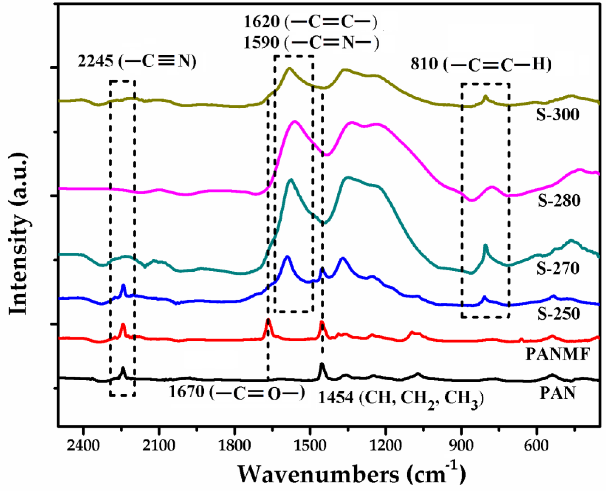
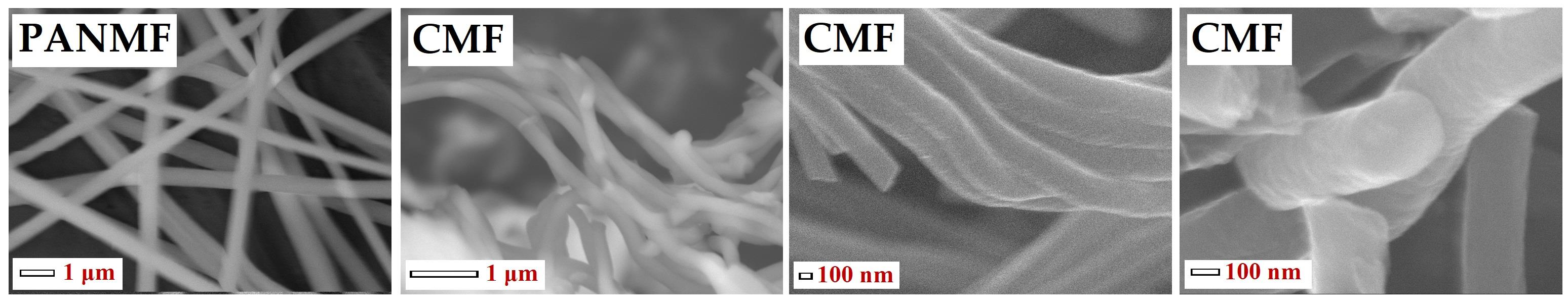
3.1. Chemical Characterization of PANMFs

To select the stabilization temperature interval, thermogravimetric analysis (TGA) was performed (Supplementary Material). The results showed that the most appropriate temperature before thermal degradation is between 250 and 300 °C (see Figure S2). Then, the effect of stabilization temperature on the chemical composition of PANMFs were analyzed by infrared spectroscopy. The infrared spectra (Figure 1) show that the PANMFs precursors present particular vibrations in ~2245, ~1670, and ~1454 cm−1, characteristics of nitrile groups (–C≡N, carbonyl groups (–C=O), and aliphatic groups (CH, CH2, and CH3), respectively [30,31,33]. After the stabilization process at temperatures between 250 to 300 °C, the intensity of signal in 2245 cm−1 decreases significantly, while the signal intensity of carbonyl groups (–C=O, ~1670 cm−1) increases, forming a wider signal corresponding to the overlapping of signals assigned to carbon–carbon double bonds (–C=C–, ~1620 cm−1) and carbon–nitrogen double bonds (–C=N). In addition to these changes, a new signal appears in ~810 cm−1, this signal is characteristic of aromatic rings (C=C–H). The reduction of nitrile groups, loss of hydrogen, and formation of aromatic structures are the result of cyclization (–C=N–), dehydrogenation (–C=C–), and oxidation (–C=O) of PANMFs. When the stabilization temperature is 280 °C, the infrared spectroscopy technique is incapable of detecting the presence of nitrile groups, suggesting that most of these groups have been converted into aromatic structures; therefore, at a temperature above 280 °C, the stabilization process is complete.
TGA (Figure S1) and FTIR (Figure 1) characterization techniques allowed a preliminary analysis of PAN microfibers. Once the PAN microfibers were synthesized, the next step was to carbonize the materials at different temperatures. The results obtained for the two batches of materials are shown below: (i) Varying the stabilization temperature (250, 270, 280, and 300 °C) but keeping the carbonization temperature constant (900 °C); and (ii) keeping the stabilization temperature constant (280 °C) but varying the carbonization temperature (600, 700, 800, 900, and 1000 °C).

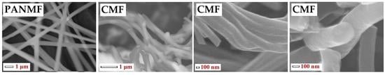
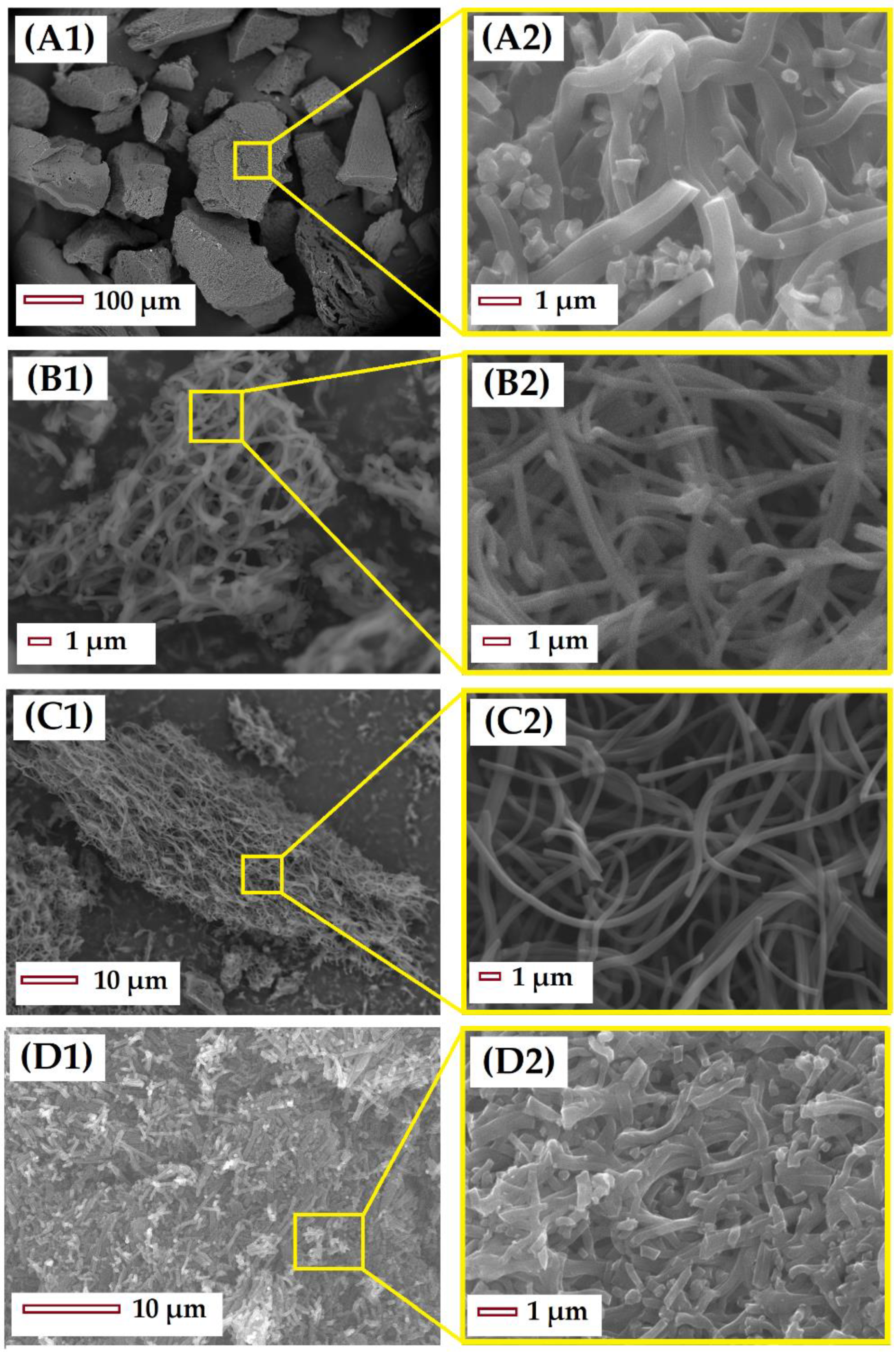
3.2. Structural and Chemical Characterization of CMF

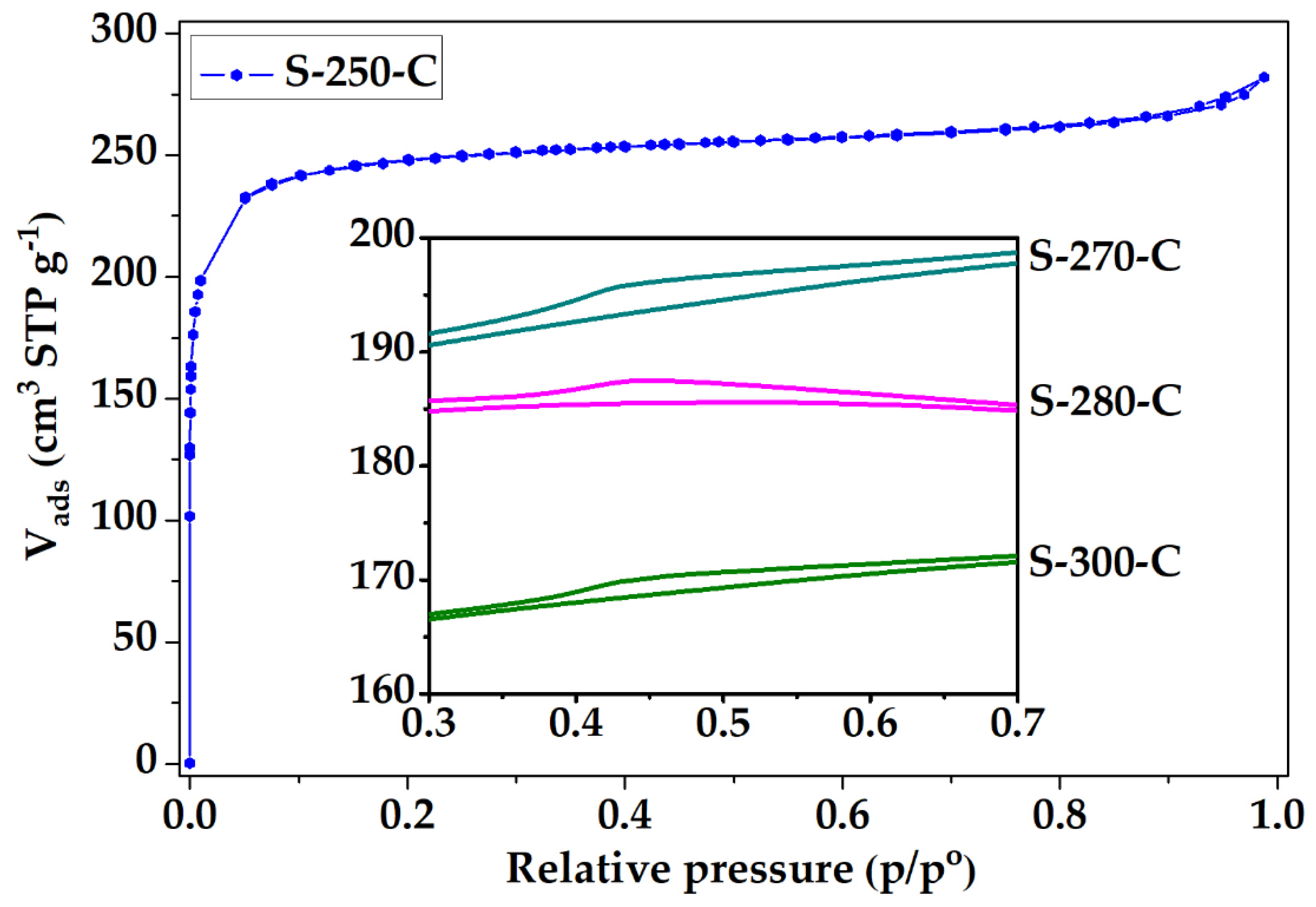
3.2.1. Impact of Stabilization Temperature

After the stabilization and carbonization of the PAN microfibers, the resultant CMF were analyzed by SEM (Figure 2). Figure 2A presents the material stabilized at 250 °C, note that low stabilization temperatures do not allow the fibrous structure of the material to be preserved after carbonization, resulting in merged microfibers without interstitial spaces. The material S-280-C preserves both the fibrous structure and the length of microfibers (Figure 2B). Meanwhile the material S-300-C, stabilized at temperatures closer to the PANMF degradation temperature, presents a break in the length; in this case, the fiber structure is also preserved, but the reduction in length causes the agglomeration of microfibers and, as a result, the interstitial space between the CMF is lost. Other characterization by TEM, XRD, XPS, and Raman was performed (more details can be found in previous publications [19,42]). TEM showed a random ordering of carbon sheets forming the structure of the microfiber, the distance between the different carbon sheets oscillate between 0.4 and 1.0 nm. XRD and Raman spectroscopy corroborates that the carbonization of PAN microfibers produces carbon structures with amorphous and graphitic character, and that the increase in the calcination temperature generates materials that are less amorphous. For illustrative purposes, the results of XRD and Raman for material stabilized at 280 °C and carbonized at 900 °C are shown in the Supplementary Material in Figure S3A,B, respectively.
The N2 adsorption isotherm of the PANMFs stabilized at 270 °C and carbonized at 900 °C is shown in Figure 3, the isotherms of the other three materials exhibited similar behavior; however, they presented a small hysteresis cycle, which are displayed in the figure frame. Based on the IUPAC classification [43], the isotherm for material S-250-C correspond to Type I, while for materials S-270-C, S-280-C, and S-300-C the isotherm type corresponds to a combination of Type I (due to the presence of microporosity) and Type IV (due to the presence of mesoporosity), with small hysteresis cycle corresponding to Type H4, characteristic of micro-mesoporous carbon. At low relative pressures (less than 0.1 in the relative pressure interval) in all materials, nitrogen adsorption is mainly attributed to the presence of micropores. At relative pressures greater than 0.35, the materials S-270-C, S-280-C, and S-300-C present a hysteresis cycle, associated with the presence of mesopores (box at the bottom of Figure 3). While the S-250-C does not present the little loop, which implies the absence of mesopores. Therefore, to obtain a totally microporous material, a stabilization temperature of 250 °C is recommended.
To explain the behavior of this material, it is considered that nitrogen adsorption in CMF can occur in two spaces: i) Between the carbon sheets that form the structure of microfibers, or ii) between the interstitial spaces that are formed by the arrangement of several microfibers. The material stabilized at 250 °C (S-250-C) does not present a hysteresis cycle due to the microfibers in this material completely fusing, as shown in Figure 3, forming a solid without interstitial spaces (Figure 2(A1,A2)). The hysteresis cycle presented by the materials S-270-C, S-280-C, and S-300-C (box in the lower part of Figure 3) is reduced with the increase of stabilization temperature, confirming the observations made by SEM (Figure 2). The material S-300-C shows shattered microfibers, which causes microfiber agglomeration and reduction in the interstitial spaces; these structural changes possibly aid the decrease in the adsorbed nitrogen capacity [42].
To obtain information from micropores, CO2 adsorption was utilized. Because of kinetic restrictions at the cryogenic temperature of nitrogen (−196 °C), the adsorption is of limited value for the characterization of very narrow micropores. One way of addressing this problem is to use CO2 (kinetic dimension 0.33 nm) as the adsorptive at 0 °C, where the saturation vapor pressure of CO2 is very high (∼35 bar) and hence the pressures required for micropore size analysis are in the moderate interval (∼0.001 to 1.000 bar). Because of these relatively high temperatures and pressures, diffusion is much faster and pores as small as 0.4 nm can be accessed [43].
The N2 and CO2 adsorption isotherms allow the calculation of the specific surface area and the average pore size distribution. The textural properties obtained from the N2 and CO2 isotherms are shown in Table 1. As observed in the isotherms of Figure 3, these materials present a high amount of micropores, which is reflected in a high specific surface area. The material stabilized at 250 °C presents a BET area of 966 m2/g; this value decreases when the stabilization temperature increases, decreasing to 635 m2/g for the material stabilized at 300 °C. In this way, the increment in the stabilization temperature plays an important role in the materials microporosity, which modifies the BET area by 35% [42].
The pore size distribution (PSD) obtained from the N2 and CO2 adsorption isotherms shows that all materials have a preferential pore diameter of ~0.8 nm. The PSD obtained from CO2 shows four preferential pore sizes (X1, X2...X4), one of which coincides with the average pore diameter obtained by N2 adsorption isotherms, 0.8 nm. The CO2 adsorption allows determining pore sizes that oscillate between 0.45 and 1.00 nm. The values obtained for the pore diameters in both cases, see Table 1, are comparable with the distances between the carbon sheets calculated by TEM micrographs [42].

3.2.2. Impact of Carbonization Temperature

The modification in the morphological structure of the carbon microfibers is mainly affected by a variation in the stabilization temperature (results shown above). While the modification in the chemical composition is due to the variation in the carbonization temperature (results shown below); therefore, a study was performed modifying this temperature. In this work, the selected stabilization temperature was fixed at 280 °C (because at this temperature the fibrous structure of the materials is preserved and, in addition, most of the nitrile groups have been eliminated, forming C=N structures). Then, carbonization of stabilized materials was performed at five different temperatures, 600, 700, 800, 900, and 1000 °C [42]. Table 2 shows a summary of the results on the morphological and chemical characteristics of these materials.
Based on the results shown in Table 2, the specific surface area rises as the carbonization temperature increases, from a BET area of 296 m2/g for SC-600 material to 822 m2/g for SC-1000 material. Considering the information provided by the nitrogen adsorption isotherms, there are some carbon sheets for the material S-250-C that present a separation of ~1.15 nm, when the carbonization temperature is increased this separation decreases until it becomes practically constant at ~0.80 nm.
CO2 adsorption isotherms allow for the determination of pore size in the ultramicropore interval, for all materials this size ranges from 0.5 to 0.8 nm. XPS analysis identifies the three main elements present in the CMF: Carbon 1s (C1s), Nitrogen 1s (N1s), and Oxygen 1s (O1s). At 600 °C, the carbon content is 79% and increases in parallel to the carbonization temperature up to 91% for the material carbonized at 1000 °C. Some investigations have demonstrated that, in specific applications, different species of nitrogen have a significant influence. For this reason, the results corresponding to high-resolution XPS spectra in the N1s are also shown in Table 2. These results were obtained from the deconvoluted spectra of XPS N1s, considering the following signals: i) residual PAN (397.8 eV), ii) pyridine-N (398.8 eV), iii) cyanide functional group, C≡N (399.5 eV), iv) pyrrolic-N/pyridone (400.5 eV), v) quaternary-N or graphitic-N (401.8 eV), vi) pyridine-N-oxide (403.1 eV), and vii) chemisorbed nitrogen oxide species/ transitions (405.12 eV). Pels et al. mentioned that the chemical environment of the nitrogen atom in pyridone is similar to pyrrolic-N; in both, the nitrogen atom contributes with two p-electrons to the system, while the hydrogen atom is bound in the plane of the ring; therefore, within the accuracy of XPS measurements, pyridone cannot be distinguished from pyrrolic-N [44].
As already mentioned, the stabilization of PAN microfibers causes the breaking of the C≡N bonds to form C=N; bonds; while with the carbonization temperature, the elimination of H2 and N2 takes place, generating different intermediate species. In the materials carbonized to 600 and 700 °C predominate pyridine nitrogen and pyrrole nitrogen; temperatures higher than 800 °C show a decrease in both species, probably due to the conversion of pyridine nitrogen to quaternary nitrogen, which are favored at high temperatures (> 800 °C) becoming the predominant groups [42]. Therefore, carbonization at temperatures above 800 °C induces the formation of new nitrogen species such as pyridone, quaternary nitrogen or graphite, pyridine nitrogen with oxidized species, and chemisorbed nitrogen [35,36,44,45,46], and causes the disappearance of the original functional groups.

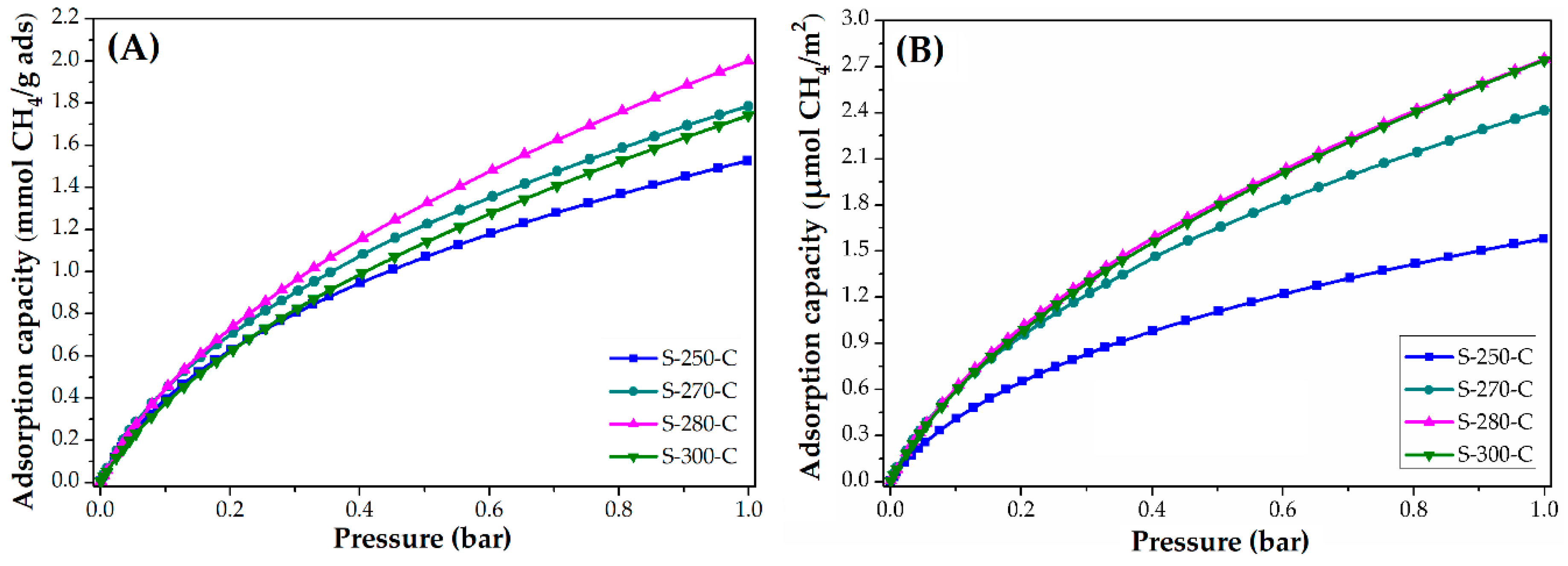
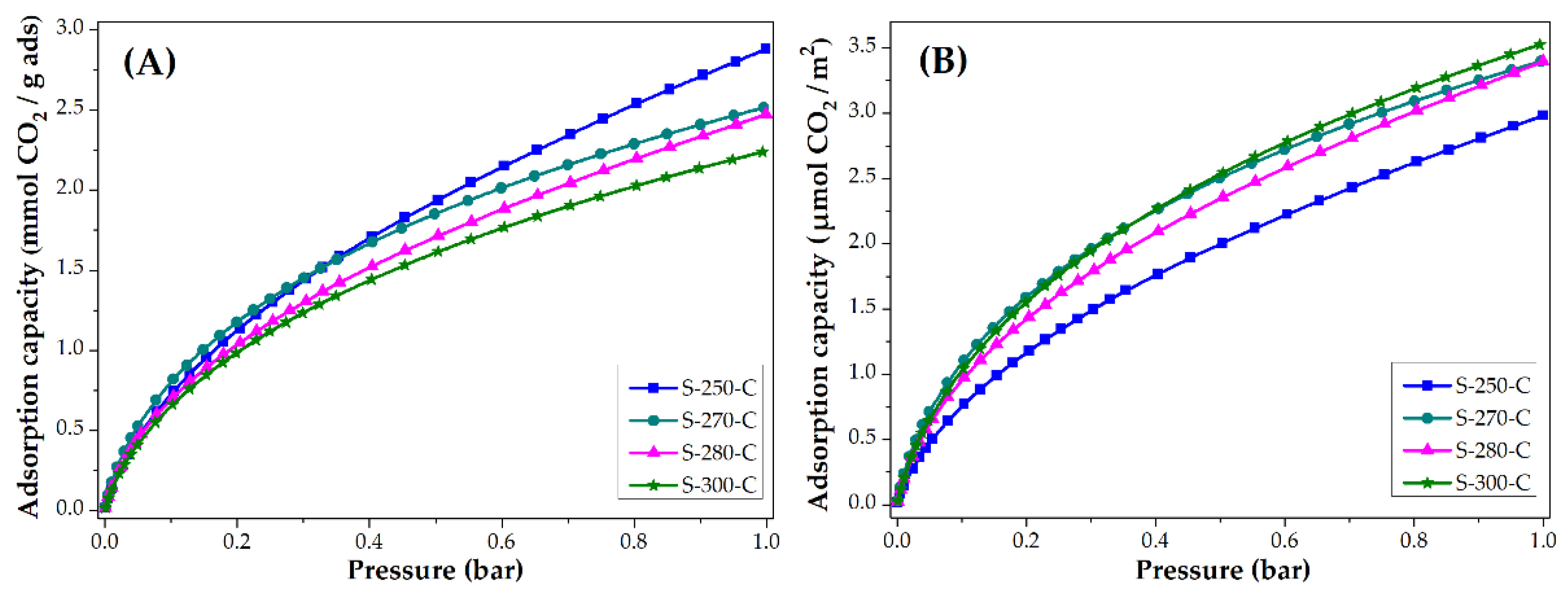
3.3. Applications: CO2 and CH4 Adsorption Capacity

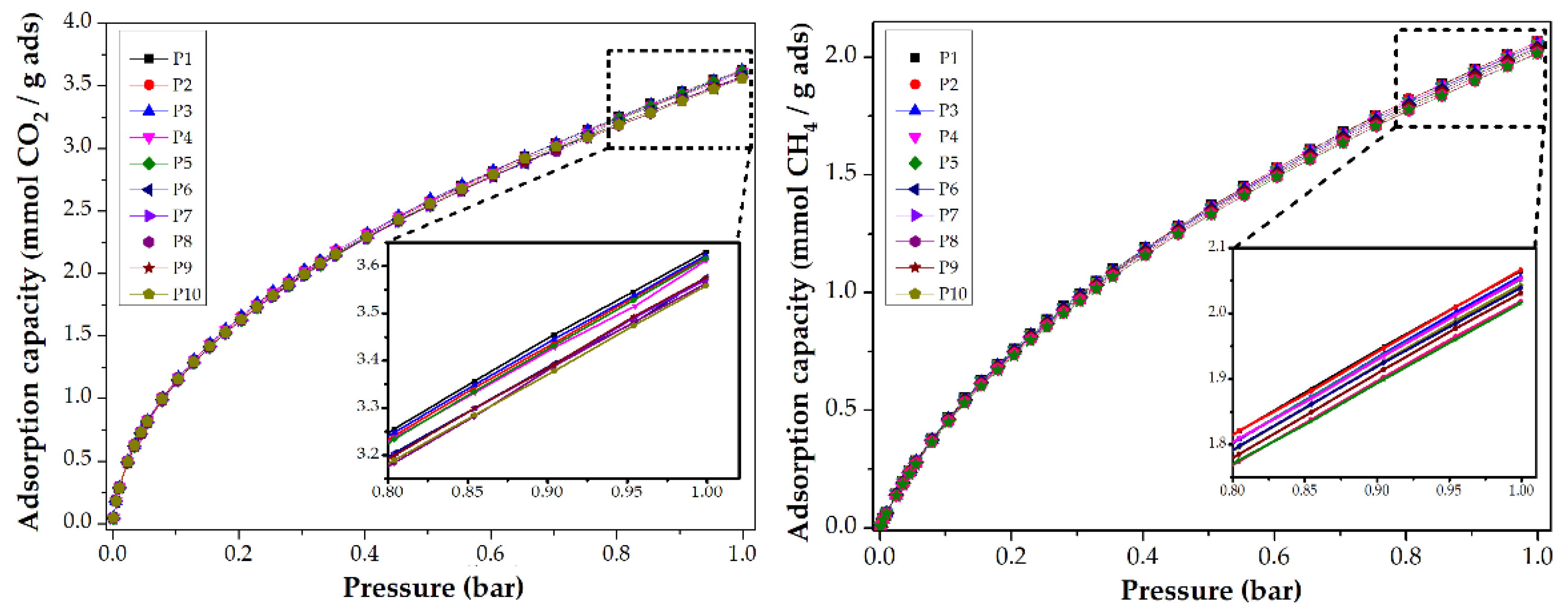
3.3.1. Impact of Stabilization Temperature

The CO2 and CH4 adsorption capacity was evaluated at 25 °C, the isotherms obtained are presented in Figure 4 and Figure 5. Figure 4 shows the adsorption isotherms in units of mmol CO2 adsorbed in one gram of adsorbent. These values are similar to the ones reported in the literature [14,15,47]. Note that the material stabilized at 250 °C adsorbs the most CO2 and the material stabilized at 300 °C adsorbs the least. To eliminate the impact of the surface area on the CO2 adsorption, the isotherms are normalized considering the BET area of each of the materials; the resulting behavior is shown in Figure 4B. The materials stabilized at 270, 280, and 300 °C adsorb similar quantities per square meter (3.4 μmol/m2, at 1 bar) that represent a greater adsorption capacity than material stabilized at 250 °C. Even though the material stabilized at 250 °C is the material with the largest surface area, it has the lowest CO2 adsorption per square meter, this may be due to the different chemical composition shown by the carbon fiber. It was shown in FTIR that this material still has nitrile groups, which can cause a lower affinity with the CO2 molecule on its surface.
Figure 5 shows the CH4 adsorption isotherms at 25 °C (A) and the normalized isotherms (B) using the BET area. In both graphs, the material stabilized at 250 °C has the lowest adsorption capacity. This means that having a larger BET area does not guarantee higher CH4 adsorption. In this way, it was observed how the affinity to CH4 is conferred mainly by the chemical composition of the carbon microfiber. This carbon microfiber presented nitrile groups; however, which may be responsible for the lower affinity to CH4 per square meter, similar to the observed in the CO2 adsorption.
In Table 3 (keeping the pressure constant at 1 bar), the CO2 adsorption capacity of CMF oscillates between 2.2 and 2.9 mmol CO2/g adsorbent (97 to 128 mg CO2/g adsorbent) at 25 °C. This value is comparable to those reported for carbon materials. For example, Kim et al. [14] obtain capacities of 2.5 mmol CO2/g for carbon microfibers activated with urea (the urea is added to increase nitrogen species). Meng et al. [15] capture between 50 and 150 mg CO2/g adsorbent on activated carbon, with treatments of KOH to increase the specific surface area. The BET area of these materials oscillates between 800 and 2200 m2/g. Comparing these materials with the CMF synthesized in this work that have similar areas (SC-900, 700 m2/g), the CO2 adsorption capacity is higher in the material SC-900 (110 mg CO2/g adsorbent) than in activated carbons (50 mg CO2/g adsorbent). Shafeeyan et al. [47] chemically modified the activated carbon with ammonium, the results obtained fluctuate between 40 and 80 mg CO2/g adsorbent, values lower than those obtained by CMF. Although activated carbon has larger BET areas than CMF, the CMF adsorbs the same or higher amounts of CO2. This may be because microfibers promote the diffusion of CO2 molecules to be absorbed or an adequate amount of chemical species (nitrogen). Bao et al. [6] measured the capture capacity of CH4 in two materials, considering the conditions at 25 °C and 1 bar: i) Metal-organic frameworks (MOFs) with an area of 1174 m2/g adsorb an approximate amount of 1 mmol/g; and ii) zeolites with an area of 330 m2/g adsorb ~0.35 mmol/g of adsorbent; this corroborates that the area does not impact, in a transcendental way, the capture of gases; but morphology and chemical composition do change the amount of CH4 adsorbed. For his part, Liu et al. [9] studied CO2 and CH4 capture in SBA-15 materials, adsorbing ~1.3 mmol/g and ~0.2 mmol/g (25 °C and 1 bar), respectively; these amounts show an improvement in CMF as gas adsorbents.
To evaluate the reusability of CMF, a collection of CO2 and CH4 adsorption isotherms at 0 and 25 °C are shown in Figure 6. After ten analyses, the CMF preserve their adsorption capacity. For the first experiment, the CMF was degassed at 200 °C by 8 h, and then the CO2 adsorption analysis was performed at 0 °C. For the second analysis, the same sample was degassed at 200 °C by 2 h and again analyzed. The following analyses followed this procedure. For the isotherms shown in the methane adsorption, the same procedure was performed at 25 °C. This allows us to conclude that the synthesized materials can be used more than ten times whilst maintaining their adsorptive capacity.

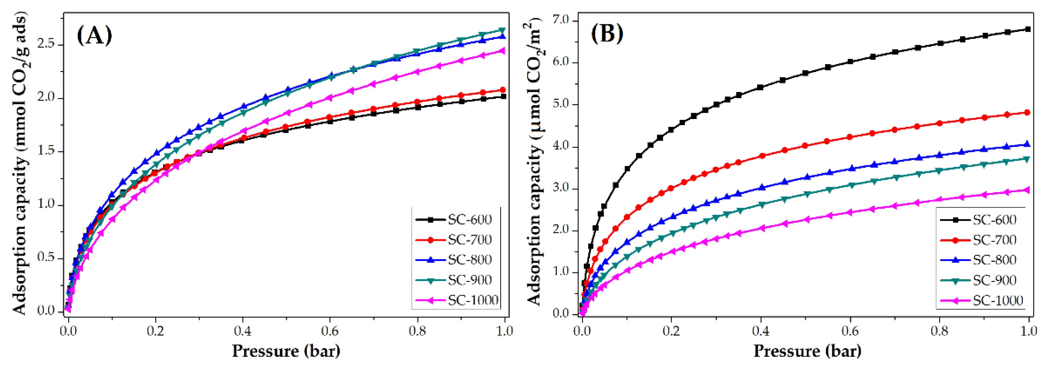
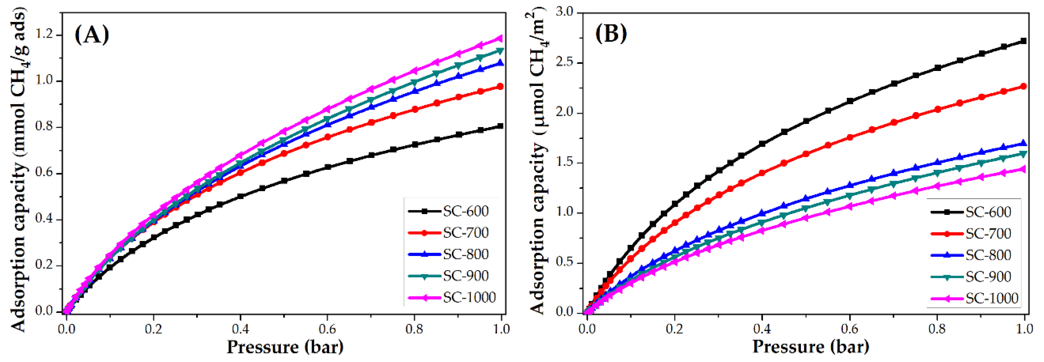
3.3.2. Impact of Carbonization Temperature

The CO2 adsorption isotherms at 25 °C of PANMF stabilized a 280 °C and carbonized at 600, 700, 800, 900, and 1000 °C are shown in Figure 7. It is observed that the increase of carbonized temperature produces an increase in the CO2 adsorption capacity. However, to observe the impact of the chemical composition of carbon microfibers on CO2 adsorption, the isotherms were normalized using the BET area, Figure 7B. The carbon microfibers decreased their CO2 adsorption capacity per square meter with the increase of carbonization temperature. This means that the increase in carbonization temperature resulted in the loss of chemical groups able to interact with CO2 but caused an increase in their BET areas. BET areas increase from 296 to 822 m2 g−1; however, the CO2 adsorption capacity does not increase proportionally to the surface area. In this way, the CO2 adsorption capacity in carbon microfiber is mainly determined by their chemical composition. For the material SC-600 and SC-700, the nitrogen species pyridinic and pyrrolic are predominant, which means these species show a greater affinity for CO2.
The CH4 adsorption isotherms at 25 °C of PANMF stabilized at 280 °C and carbonized at 600, 700, 800, 900, and 1000 °C are shown in Figure 8. Similarly to that observed in the CO2 adsorption, the increase of carbonized temperature produces an increase in the CH4 adsorption capacity. Once the isotherms are normalized, the material that adsorbs a greater amount of CH4 corresponds to the material with a smaller specific surface area, which implies that the interaction is also mainly due to the presence of the functional groups that exist in this material, primarily the pyridinic and pyrrolic groups, and the quaternary nitrogen content remains constant in all materials. It should be noted that, although the behavior is similar to CO2 adsorption, the amount adsorbed is lower in the case of CH4. Consider SC-600 material at 1 bar, for CO2 an amount of ~6.5 µmol/m2 is adsorbed and for CH4 ~2.8 µmol/m2; therefore, carbon microfibers present more affinity to the CO2 molecule, probably due to the presence of a polar momentum.
The adsorption capacity of CO2 and CH4 per unit of adsorbent grams (shown in Table 4) rises slightly with the increase in carbonization temperature, however, when the results are normalized considering the BET area, the adsorption capacity diminishes with increasing temperature, which implies that the CO2 and CH4 capture capacity is directly related to the number of nitrogen species present in each material and not to the specific surface area. This behavior must be considered in the design of novel adsorbents materials, where the chemical composition of the surface is very important in order to obtain a high adsorbent material for greenhouse gases.

4. Conclusions

The stabilization temperature allowed the morphology of CMF to be modified, increasing or decreasing the specific surface area; whereas carbonization temperature changed the chemical composition, this variability being the one that directly affects the capture of CO2 and CH4. The results corroborate that the specific surface area is not the determining factor for the adsorption of greenhouse gases. Thus, it is very important to take into account the chemical structure, especially for the enhancement of the interaction between CO2 and CH4 with pyridinic, pyrrolic, and quaternary groups. In both cases the amount adsorbed is similar and even improved compared to other materials such as zeolites, silica mesoporous, and activated carbon, oscillating from 2.0 to 2.6 mmol CO2/g and 0.8 to 1.2 mmol CH4/g.

Supplementary Materials

The following are available online at https://www.mdpi.com/2079-6439/7/10/81/s1, Figure S1: Nomenclature of PAN microfibers stabilized and carbonized, synthetized by electrospinning. Figure S2: TG/DTA analysis of polyacrylonitrile microfibers (PANMFs), synthesized by the electrospinning method. Reaching a temperature of 300 °C the material begins to degrade thermally, therefore, in this work, an interval between 250 °C and 300 °C was selected. Figure S3: PAN microfibers stabilized at 280 °C and carbonized at 900 °C: (A) XRD analysis, the high amplitude of the peak between 5o and 35° in 2θ indicates a high degree of amorphicity on the graphene sheets. The signal in the plane (100) is attributed to the graphitic character of the material, and (B) Raman spectroscopy analysis, which exhibit two peaks, centered at 1360 cm−1 and 1600 cm−1, they are known as D and G peaks, respectively. The first peak is attributed to disordered carbon films while the second one is attributed to the presence of graphitic type ordered structures.

Author Contributions

Investigation and writing—original draft preparation, R.O.-L; supervision, J.M.E.-S.; writing—review and editing, I.J.P.-H. and A.H.-G.; project administration, A.D.-O.

Funding

This research was funded by the Consejo Nacional de Ciencia y Tecnología (CONACyT) and the project SECITI/080/2017. The SEM images were made possible by Paty Castillo (UAM-I) and Anabel Gonzalez Diaz (UJAT). ROL thanks CONACyT for the support with the scholarship 268040.

Acknowledgments

R.O.-L. thanks Ignacio González–Martínez and Guadalupe Ramos-Sánchez for all their academic support.

Conflicts of Interest

The authors declare no conflict of interest.

References

  1. Zhang, X.B.; Xu, J. Optimal policies for climate change: A joint consideration of CO2 and methane. Appl. Energy 2018, 211, 1021–1029. [Google Scholar] [CrossRef]
  2. Meng, L.-Y.; Park, S.-J. Superhydrophobic carbon-based materials: A review of synthesis, structure, and applications. Carbon Lett. 2014, 15, 89–104. [Google Scholar] [CrossRef]
  3. Lee, S.Y.; Park, S.J. A review on solid adsorbents for carbon dioxide capture. J. Ind. Eng. Chem. 2015, 23, 1–11. [Google Scholar] [CrossRef]
  4. Chaffee, A.L.; Knowles, G.P.; Liang, Z.; Zhang, J.; Xiao, P.; Webley, P.A. CO2 capture by adsorption: Materials and process development. Int. J. Greenh. Gas Control. 2007, 1, 11–18. [Google Scholar] [CrossRef]
  5. Bezerra, D.P.; Silva, F.W.M.D.; Moura, P.A.S.D.; Sousa, A.G.S.; Vieira, R.S.; Rodriguez-Castellon, E.; Azevedo, D.C.S. CO2 adsorption in amine-grafted zeolite 13X. Appl. Surf. Sci. 2014, 314, 314–321. [Google Scholar] [CrossRef]
  6. Bao, Z.; Yu, L.; Ren, Q.; Lu, X.; Deng, S. Adsorption of CO2 and CH4 on a magnesium-based metal organic framework. J. Colloid Interface Sci. 2011, 353, 549–556. [Google Scholar] [CrossRef]
  7. Yong, Z.; Mata, V.; Rodrigues, E. Adsorption of Carbon Dioxide on Basic Alumina at High Temperatures. J. Chem. Eng. Data 2000, 45, 1093–1095. [Google Scholar] [CrossRef]
  8. Liu, X.; Zhou, L.; Fu, X.; Sun, Y.; Su, W.; Zhou, Y. Adsorption and regeneration study of the mesoporous adsorbent SBA-15 adapted to the capture/separation of CO2 and CH4. Chem. Eng. Sci. 2007, 62, 1101–1110. [Google Scholar] [CrossRef]
  9. Liu, X.; Li, J.; Zhou, L.; Huang, D.; Zhou, Y. Adsorption of CO2, CH4 and N2 on ordered mesoporous silica molecular sieve. Chem. Phys. Lett. 2005, 415, 198–201. [Google Scholar] [CrossRef]
  10. Munguía-Cortés, L.; Pérez-Hermosillo, I.; Ojeda-López, R.; Esparza-Schulz, J.M.; Felipe-Mendoza, C.; Cervantes-Uribe, A.; Domínguez-Ortiz, A. APTES-functionalization of SBA-15 using ethanol or toluene: Textural characterization and sorption performance of carbon dioxide. J. Mex. Chem. Soc. 2017, 61, 273–281. [Google Scholar] [CrossRef]
  11. Ojeda-López, R.; Pérez-Hermosillo, I.J.; Marcos Esparza-Schulz, J.; Cervantes-Uribe, A.; Domínguez-Ortiz, A. SBA-15 materials: Calcination temperature influence on textural properties and total silanol ratio. Adsorption 2015, 21, 659–669. [Google Scholar] [CrossRef]
  12. Zhang, L.; Aboagye, A.; Kelkar, A.; Lai, C.; Fong, H. A review: Carbon nanofibers from electrospun polyacrylonitrile and their applications. J. Mater. Sci. 2014, 49, 463–480. [Google Scholar] [CrossRef]
  13. Meng, L.Y.; Park, S.J. Effect of heat treatment on CO2 adsorption of KOH-activated graphite nanofibers. J. Colloid Interface Sci. 2010, 352, 498–503. [Google Scholar] [CrossRef] [PubMed]
  14. Kim, D.W.; Jung, D.W.; Adelodun, A.A.; Jo, Y.M. Evaluation of CO2 adsorption capacity of electrospun carbon fibers with thermal and chemical activation. J. Appl. Polym. Sci. 2017, 134, 45534–45541. [Google Scholar] [CrossRef]
  15. Meng, L.Y.; Park, S.J. One-pot synthetic method to prepare highly N-doped nanoporous carbons for CO2 adsorption. Mater. Chem. Phys. 2014, 143, 1158–1163. [Google Scholar] [CrossRef]
  16. Kim, J.; Maiti, A.; Lin, L.C.; Stolaroff, J.K.; Smit, B.; Aines, R.D. New materials for methane capture from dilute and medium-concentration sources. Nat. Commun. 2013, 4, 1694–1697. [Google Scholar] [CrossRef]
  17. Golebiowska, M.; Roth, M.; Firlej, L.; Kuchta, B.; Wexler, C. The reversibility of the adsorption of methane-methyl mercaptan mixtures in nanoporous carbon. Carbon 2012, 50, 225–234. [Google Scholar] [CrossRef]
  18. Park, S.-J. Carbon Fibers; Springer: New York, NY, USA; London, UK, 2015; Volume 210, ISBN 9789401794770. [Google Scholar]
  19. Ojeda-López, R.; Ramos-Sánchez, G.; Esparza-Schulz, J.M.; Lartundo, L.; Domínguez-Ortiz, A. On site formation of N-doped carbon nanofibers, an efficient electrocatalyst for fuel cell applications. Int. J. Hydrogen Energy 2017, 42, 30339–30348. [Google Scholar] [CrossRef]
  20. Alarifi, I.M.; Khan, W.S.; Asmatulu, R. Synthesis of electrospun polyacrylonitrile-derived carbon fibers and comparison of properties with bulk form. PLoS ONE 2018, 13, 1–14. [Google Scholar] [CrossRef]
  21. Yuan, L.; Wei, X.; Martinez, J.P.; Yu, C.; Panahi, N.; Gan, J.B.; Zhang, Y.; Gan, Y.X. Reaction Spinning Titanium Dioxide Particle-Coated Carbon Fiber for Photoelectric Energy Conversion. Fibers 2019, 7, 49. [Google Scholar] [CrossRef]
  22. Gan, Y.; Yu, C.; Panahi, N.; Gan, J.; Cheng, W. Processing Iron Oxide Nanoparticle-Loaded Composite Carbon Fiber and the Photosensitivity Characterization. Fibers 2019, 7, 25. [Google Scholar] [CrossRef]
  23. Xue, C.; Wilson, L.D. A Spectroscopic Study of Solid-Phase Chitosan/Cyclodextrin-Based Electrospun Fibers. Fibers 2019, 7, 48. [Google Scholar] [CrossRef]
  24. Rahaman, M.S.A.; Ismail, A.F.; Mustafa, A.A. Review of heat treatment on polyacrylonitrile fiber. Polym. Degrad. Stab. 2007, 92, 1421–1432. [Google Scholar] [CrossRef]
  25. Huang, Z.M.; Zhang, Y.Z.; Kotaki, M.; Ramakrishna, S. A review on polymer nanofibers by electrospinning and their applications in nanocomposites. Compos. Sci. Technol. 2003, 63, 2223–2253. [Google Scholar] [CrossRef]
  26. Mottaghitalab, V.; Haghi, A.K. A study on electrospinning of polyacrylonitrile nanofibers. Korean J. Chem. Eng. 2011, 28, 114–118. [Google Scholar] [CrossRef]
  27. Paul, P. An Introduction to Electrospinning Process. Man-Made Text. India 2005, 48, 367–371. [Google Scholar]
  28. Nataraj, S.K.; Yang, K.S.; Aminabhavi, T.M. Polyacrylonitrile-based nanofibers—A state-of-the-art review. Prog. Polym. Sci. 2012, 37, 487–513. [Google Scholar] [CrossRef]
  29. Wu, M.; Wang, Q.; Li, K.; Wu, Y.; Liu, H. Optimization of stabilization conditions for electrospun polyacrylonitrile nanofibers. Polym. Degrad. Stab. 2012, 97, 1511–1519. [Google Scholar] [CrossRef]
  30. Dalton, S.; Heatley, F.; Budd, P.M. Thermal stabilization of polyacrylonitrile fibres. Polymer 1999, 40, 5531–5543. [Google Scholar] [CrossRef]
  31. Xue, Y.; Liu, J.; Liang, J. Correlative study of critical reactions in polyacrylonitrile based carbon fiber precursors during thermal-oxidative stabilization. Polym. Degrad. Stab. 2013, 98, 219–229. [Google Scholar] [CrossRef]
  32. Ko, T.-H. The influence of pyrolisis properties and microstructure of modified PAN fiber during carbonization. J. Appl. Polym. Sci. 1991, 43, 589–600. [Google Scholar] [CrossRef]
  33. Wangxi, Z.; Jie, L.; Gang, W. Evolution of structure and properties of PAN precursors during their conversion to carbon fibers. Carbon 2003, 41, 2805–2812. [Google Scholar] [CrossRef]
  34. Liu, J.; Wang, P.H.; Li, R.Y. Continuous carbonization of polyacrylonitrile-based oxidized fibers: Aspects on mechanical properties and morphological structure. J. Appl. Polym. Sci. 1994, 52, 945–950. [Google Scholar] [CrossRef]
  35. Laffont, L.; Monthioux, M.; Serin, V.; Mathur, R.B.; Guimon, C.; Guimon, M.F. An EELS study of the structural and chemical transformation of PAN polymer to solid carbon. Carbon 2004, 42, 2485–2494. [Google Scholar] [CrossRef]
  36. Kumar, A.; Ganguly, A.; Papakonstantinou, P. Thermal stability study of nitrogen functionalities in a graphene network. J. Phys. Condens. Matter 2012, 24, 235503–235508. [Google Scholar] [CrossRef]
  37. Schierholz, R.; Kröger, D.; Weinrich, H.; Gehring, M.; Tempel, H.; Kungl, H.; Mayer, J.; Eichel, R.A. The carbonization of polyacrylonitrile-derived electrospun carbon nanofibers studied by: In situ transmission electron microscopy. RSC Adv. 2019, 9, 6267–6277. [Google Scholar] [CrossRef]
  38. Arbab, S.; Teimoury, A.; Mirbaha, H.; Adolphe, D.C.; Noroozi, B.; Nourpanah, P. Optimum stabilization processing parameters for polyacrylonitrile-based carbon nanofibers and their difference with carbon (micro) fibers. Polym. Degrad. Stab. 2017, 142, 198–208. [Google Scholar] [CrossRef]
  39. Eddib, A.A.; Chung, D.D.L. Electric permittivity of carbon fiber. Carbon 2019, 143, 475–480. [Google Scholar] [CrossRef]
  40. Zhou, Z.; Lai, C.; Zhang, L.; Qian, Y.; Hou, H.; Reneker, D.H.; Fong, H. Development of carbon nanofibers from aligned electrospun polyacrylonitrile nanofiber bundles and characterization of their microstructural, electrical, and mechanical properties. Polymer 2009, 50, 2999–3006. [Google Scholar] [CrossRef]
  41. Arshad, S.N.; Naraghi, M.; Chasiotis, I. Strong carbon nanofibers from electrospun polyacrylonitrile. Carbon 2011, 49, 1710–1719. [Google Scholar] [CrossRef]
  42. Ojeda-López, R.; Pérez-Hermosillo, I.J.; Esparza-Schulz, J.M.; Ramos-Sánchez, G.; Domínguez-Ortiz, A. Controlling Structural and Electrochemical Properties of CNF through Calcination. In Advances in Materials Science Research; Maryann, C., Wythers, E.D., Eds.; Nova Science Publishers: New York, NY, USA, 2019; pp. 79–118. ISBN 6312317269. [Google Scholar]
  43. Thommes, M.; Kaneko, K.; Neimark, A.V.; Olivier, J.P.; Rodriguez-Reinoso, F.; Rouquerol, J.; Sing, K.S.W. Physisorption of gases, with special reference to the evaluation of surface area and pore size distribution (IUPAC Technical Report). Pure Appl. Chem. 2015, 87, 1051–1069. [Google Scholar] [CrossRef] [Green Version]
  44. Pels, J.R.; Kapteijn, F.; Moulijn, J.A.; Zhu, Q.; Thomas, K.M. Evolution of nitrogen functionalities in carbonaceous materials during pyrolysis. Carbon 1995, 33, 1641–1653. [Google Scholar] [CrossRef]
  45. Fitzer, E.; Müller, D.J. The influence of oxygen on the chemical reactions during stabilization of pan as carbon fiber precursor. Carbon 1975, 13, 63–69. [Google Scholar] [CrossRef]
  46. Roldán, L.; Armenise, S.; Marco, Y.; García-Bordejé, E. Control of nitrogen insertion during the growth of nitrogen-containing carbon nanofibers on cordierite monolith walls. Phys. Chem. Chem. Phys. 2012, 14, 3568–3575. [Google Scholar] [CrossRef] [Green Version]
  47. Shafeeyan, M.S.; Daud, W.M.A.W.; Houshmand, A.; Arami-Niya, A. Ammonia modification of activated carbon to enhance carbon dioxide adsorption: Effect of pre-oxidation. Appl. Surf. Sci. 2011, 257, 3936–3942. [Google Scholar] [CrossRef]
Figure 1. FTIR spectra of PAN, PANMF, and PANMFs stabilized at 250, 270, 280, and 300 °C.
Fibers 07 00081 g001
Figure 2. SEM images of CMF stabilized and carbonized: (A) S-250-C, (B) S-270-C, (C) S-280-C, and (D) S-300-C. The images on the right (A2, B2, C2, and D2) are zoomed in images of a region of the figures on the left (A1, B1, C1, and D1).
Fibers 07 00081 g002
Figure 3. Nitrogen physisorption isotherms of CMF.
Fibers 07 00081 g003
Figure 4. CO2 adsorption isotherms of CMF: (A) mmol CO2/g adsorbent and (B) µmol CO2/m2.
Fibers 07 00081 g004
Figure 5. CH4 adsorption isotherms of CMF: (A) mmol CH4/g adsorbent and (B) µmol CH4/m2.
Fibers 07 00081 g005
Figure 6. CO2 and CH4 adsorption isotherms at 0 and 25 °C, respectively, of PANMF stabilized at 280 °C and carbonized at 900 °C: Evaluation of reusability.
Fibers 07 00081 g006
Figure 7. CO2 adsorption isotherms at 25 °C of PANMF stabilized at 280 °C and carbonized: (A) mmol CO2/g adsorbent and (B) µmol CO2/m2.
Fibers 07 00081 g007
Figure 8. CH4 adsorption isotherms at 25 °C of PANMF stabilized a 280 °C and carbonized: (A) mmol CH4/g adsorbent and (B) µmol CH4/m2.
Fibers 07 00081 g008
Table 1. Structural properties by N2 and CO2 adsorption of PANMFs stabilized at 250, 270, 280, and 300 °C, and carbonized at 900 °C. SBET—BET area; DNLDFT—preferential pore diameter calculated by the NLDFT model; in the case of CO2 adsorption, four pore sizes were observed (X1, X2, X3, and X4).
AdsorbateTextural PropertiesS-250-CS-270-CS-280-CS-300-C
N2SBET (m2 g−1)966.0740.0728.0635.0
DNLDF (nm)0.790.800.810.82
CO2DNLDF, X1 (nm) 0.510.510.510.51
DNLDF, X2 (nm) 0.590.590.590.59
DNLDF, X3 (nm) 0.680.710.690.71
DNLDF, X4 (nm) 0.820.830.820.83
Table 2. Textural and chemical properties of PANMFs carbonized at 600, 700, 800, 900, and 1000 °C. SBET—BET area; DNLDFT—preferential pore diameter calculated by the NLDFT model; in the case of CO2 adsorption, four pore sizes were observed (X1, X2, X3, and X4). XPS general for carbon, nitrogen, and oxygen. High-resolution XPS spectra in the N1s.
PROPERTIESSC-600SC-700SC-800SC-900SC-1000
SBET (m2 g−1)296431635710822
DNLDF (nm)1.150.800.800.830.83
DNLDF, X1 (nm) 0.510.510.510.510.51
DNLDF, X2 (nm) 0.590.590.590.590.59
DNLDF, X3 (nm) 0.730.720.720.700.72
DNLDF, X4 (nm) 0.830.830.830.830.83
C1s7882859091
N1s1613955
O1s65654
Pyridinic4.483.642.791.150.9
C≡N3.681.950.90.50.45
Pyrrolic or pyridine4.643.121.80.650.55
Quaternary or graphite2.082.62.5222.1
Pyridinic with oxidized species0.640.780.630.50.5
Table 3. CO2 and CH4 adsorption capacity (1 bar, 25 °C) in materials stabilized at 250, 270, 280, and 300 °C. g ads—gram of adsorbent of CMF.
CMFCO2CH4
mmol CO2/g adsmg CO2/g adsμmol CO2/m2 (Normalized)mmol CH4/g adsmg CH4/g adsμmol CH4/m2 (Normalized)
S-250-C2.9127.63.01.524.51.6
S-270-C2.5110.03.41.828.72.4
S-280-C2.5110.03.42.032.12.8
S-300-C2.296.83.51.727.92.8
Table 4. CO2 and CH4 adsorption capacity (1 bar, 25 °C) in materials carbonized at 600, 700, 800, 900, and 1000 °C. g ads—gram of adsorbent of CMF.
CMFCO2CH4
mmol CO2/g adsmg CO2/g adsμmol CO2/m2 (Normalized)mmol CH4/g adsmg CH4/g adsμmol CH4/m2 (Normalized)
SC-6002.088.76.80.812.82.7
SC-7002.192.44.81.016.02.3
SC-8002.6114.44.11.016.01.7
SC-9002.6114.43.71.117.61.6
SC-10002.4105.63.01.219.21.4

