Abstract
The effectiveness of a new retrofitting technique to upgrade the structural behaviour of reinforced concrete (RC) deep beams without steel stirrups using carbon fibre-reinforced polymer (CFRP) ropes as the only transverse shear reinforcement is experimentally investigated. Five shear-critical beams with rectangular and T-shaped cross-section are tested under monotonic loading. The strengthening schemes include (a) one vertical and one diagonal single-link CFRP rope that are internally applied through the web of the rectangular beam using an embedded through-section (ETS) system and (b) two vertical U-shaped double-link ropes that are applied around the perimeter of the web of the flanged beam using a near-surface-mounted (NSM) system. In both cases, the free lengths of the CFRP ropes have been properly anchored using epoxy bonded lap splices of the rope as NSM at (a) the top and the bottom of the web of the rectangular beam and (b) the top of the slab of the T-beam. Promising results have been derived, since the proposed strengthening technique enhanced the strength and altered the brittle shear failure to a ductile flexural one. The experimental results of this study were also used to check the validity of an analytical approach to predict the strength of shear strengthened deep beams using FRP ropes as transverse link reinforcement.
1. Introduction
Retrofitting of shear-critical reinforced concrete (RC) beams using externally bonded (EB) fibre-reinforced polymer (FRP) sheets and laminates is a promising and extensively studied technique. The effectiveness of this strengthening method depends on the bond performance of the concrete-adhesive-FRP interfaces. However, premature debonding failure is common in flanged beams with T-shaped cross-sections and U-shaped EB-FPR retrofitting schemes since the slab usually prevents the wrapping around the cross-section or/and the proper end anchorage of the externally applied composite material [1,2]. Especially in the case of beam-column joints under lateral reversals, the anchorage of EB-FRP sheets used for the shear strengthening of the joint area proved to be crucial, since debonding of these sheets during the imposed cyclic loading is followed by rapid joint shear failure [3,4].
For this reason, several experimental works have been conducted to examine advanced shear strengthening and anchorage systems. Ombres [5] studied the shear behaviour of RC beams retrofitted with a new type of cement based fibre-reinforced composite materials, and reduced fabric-to-matrix debonding failures have been observed in the U-shaped retrofitting schemes. In order to avoid premature debonding failures at low strains, a promising technique known as near-surface-mounted (NSM) was developed [6]. In this technique, FRP plates [7] or rods [8] are applied into pre-drilled vertical or shear-favourably inclined grooves on the concrete cover at the perimeter of the beam using epoxy adhesive. Compared to the EB method, the NSM system offers an advanced level of strengthening that is less prone to the premature failure, and better bond conditions for the FRP strengthening system, due to the higher confinement applied by the concrete that surrounds the FRPs [9,10]. Oehlers et al. [11] also observed that the effectiveness of the NSM system increased as this reinforcement applied into a deeper groove on the concrete cover. This technique can be useful only in cases when the concrete cover of the members provides sufficient thickness for grooves of a required size to be accommodated.
For this reason, an alternative strengthening technique has been proposed in the literature for shear upgrading of RC beams using embedded through-section (ETS) reinforcement. According to this retrofitting system, steel or FRP bars are inserted inside vertical or with shear-favourably inclination pre-drilled holes through the web of the beam, and are bonded to the surrounding concrete using an epoxy adhesive [12,13]. In this method, the concrete provides greater confinement to the ETS reinforcements by improving their bond performance. Further, when concrete cover does not have the requisite thickness or the concrete surface is characterised by low quality to guarantee the effectiveness of the NSM or EB technique, ETS can be technically proved to be sufficiently effective [14]. In the experimental study of Chaallal et al. [15] the effectiveness of ETS, NSM, and EB shear strengthening systems using carbon FRP (CFRP) bars as a ETS and NSM reinforcement, and EB U-jacket FRP sheets has been compared. The highest efficiency was proven by the application of the ETS method since the shear brittle failure was altered to a ductile flexural one.
Recently, the use of FRP ropes has been examined as a shear retrofitting reinforcement [16,17] in RC beams, as an external confining reinforcement in RC columns [18] and as an anchorage reinforcement in FRP shear-strengthened RC beams [19]. Kaya et al. [20] investigated two different strengthening types in terms of anchorage methods of CFRP ropes used for the flexural retrofit of beam-critical regions under cyclic reversal load. The few aforementioned experimental studies featured the prospects for the development of a wider use and further investigation of the FRP ropes as strengthened RC members demonstrated improved response. However, the research carried out on the strengthening of RC beams with FRP ropes against shear was very limited and has preliminary and exploratory character so far.
This paper presents the findings of an experimental study aiming at the investigation of the efficiency of a new shear strengthening method to upgrade the performance of RC deep beams with rectangular and T-shaped cross-section using CFRP ropes (SikaWrap FX-50C) (Sika Hellas ABEE, Kryoneri, Greece) as the only transverse shear link reinforcement. Two different strengthening techniques were selected, which include (a) one vertical and one shear-favourably inclined single-link rope that were internally applied through the web of the rectangular beam as ETS reinforcement, and (b) two vertical U-shaped double-link ropes as NSM reinforcements applied at the perimeter of the web of the flanged beam. Further, the effectiveness of the applied NSM anchorage system of the FRP ropes in both cases is also examined. Furthermore, an analytical approach for the evaluation of the shear strength of RC beams retrofitted in shear with FRP ropes is also developed. The contribution of the strengthening FRP reinforcement is estimated using the analytical models proposed by Mofidi et al. [13], and Paretti and Nanni [21]. The presented analysis is also used to predict the shear strength and the expected failure mode of the examined beams.
2. Experimental Program
The experimental program included five (5) RC deep beams 1.6 m long subjected to four-point monotonic loading. Three beams had rectangular cross-sections with codified names “R”, “R-S”, and “R-FRP” and two beams had T-shaped cross-sections with codified names “T” and “T-FRP”. The rectangular cross-sections had a width to height ratio b/h = 150/300 mm, effective depth d = 265 mm, shear span α = 500 mm, and shear span-to-depth ratio α/d = 1.89, as presented in Figure 1. The T-section beams had web width to height ratio bw/h = 150/300 mm, flange width bf = 350 mm, flange thickness hf = 50 mm, effective depth d = 265 mm, shear span α = 400 mm, and shear span-to-depth ratio α/d = 1.51, as illustrated in Figure 2.

Figure 1.
Geometry and reinforcement details of the beams with rectangular cross-sections.
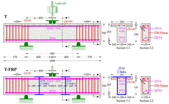
Figure 2.
Geometry and reinforcement details of the flanged beams with T-shaped cross-sections.
All specimens had the same tensional and compressional longitudinal reinforcements, consisting of two common deformed steel bars of diameter 14 mm (2∅14 top and 2∅14 bottom bars). Reference beams “R” and “T” with rectangular and T-shaped cross-sections, respectively, had no transverse shear reinforcement within the shear span. Beam “R-S” had a rectangular cross-section and a low ratio of stirrups; one mild steel closed stirrup of diameter 8 mm was present at each shear span. Beams “R-FRP” and “T-FRP”, with rectangular and T-shaped cross-sections, respectively, were strengthened in shear prior to testing using CFRP ropes (SikaWrap FX-50C) as the only transverse link reinforcement. The geometrical and reinforcement features of the examined beams are presented with detail in Figure 1 and Figure 2.
Two different shear strengthening techniques are examined in this study. In the rectangular beam “R-FRP”, the CFRP ropes were internally applied through the middle of the web of the beam as ETS reinforcements. One vertical single-link rope was installed at the right shear span and one shear-favourably inclined single-link rope was installed at the left shear span, both at a distance of 185 mm from the point of the applied load. Concerning the flanged T-section beam, the CFRP ropes were inserted in epoxied grooves that had been drilled at the perimeter of the web as NSM reinforcements. One vertical U-shaped double-link rope was installed at each shear span. The shear strengthening systems of the tested beams are schematically illustrated in Figure 1 and Figure 2.
It is noted that the application of the above strengthening techniques in real existing RC beams is mainly restricted by the existence of a strong heavy masonry wall on the top or/and at the bottom of the beam, which is rather difficult to be removed and reconstructed.
2.1. Materials
The rope used for shear strengthening of the beams consisted of a bundle of flexible and unidirectional carbon fibres. According to the manufacturer’s data sheet, the nominal cross-section area, the minimum elongation at break, and the modulus of elasticity of the carbon fibres before impregnation were 28 mm2, 1.6%, and 240 GPa, respectively. The CFRP rope was impregnated in epoxy resin with tensile strength 45 MPa, maximum elongation 1.5%, elastic modulus 3.5 GPa, and low-viscosity. The impregnated CFRP rope had a nominal diameter of 10 mm, nominal ultimate tensile strength of 2.1 GPa, and a modulus of elasticity of 230 GPa. The holes and the grooves where the CFRP ropes were inserted were filled and sealed, respectively, using epoxy paste with modulus of elasticity 4.5 GPa and tensile strength 30 MPa.
Standard concrete cylinders of 150 mm × 300 mm were tested by compression and splitting tests on the day of the tests. The mean cylinder compressive and splitting tensile strength of the concrete of the beams were 28.0 MPa and 2.70 MPa, respectively (see also the Supplementary File 1: “Test-Data.xlsx” for concrete compressive stress—strain curves and strength data). Further, the maximum aggregate size of the used concrete is 16 mm. Furthermore, the yield tensile strength of the ∅14 deformed steel bars and the ∅8 mild steel stirrups were 580 MPa and 310 MPa, respectively.
2.2. FRP Strengthening Techniques
The examined ETS strengthening technique is illustrated in Figure 3 and the application steps were: (1) 15-mm-diameter vertical and inclined holes were drilled through the depth and at the middle of the cross-section of the RC beam, whereas radial square grooves were opened at the top and the bottom of the web for the effective anchorage of the CFRP ropes (Figure 3a); (2) the dust inside the holes and the grooves was removed using compressed air in order to ensure improved adhesion between concrete and resin; (3) the ropes were impregnated for approximately half an hour using epoxy resin with low-viscosity according to the manufacturer’s recommendations before inserting them into the holes (Figure 3b,c); (4) each hole and groove of the anchorage region were partially filled by epoxy resin injection using a resin gun (Figure 3d); (5) the 10-mm-diameter impregnated CFRP ropes were carefully inserted with a metallic wire as a guide inside the drilled holes, and their free lengths were installed into the grooves as NSM anchorage system (Figure 3e); (6) additional epoxy paste was injected into the holes and applied to the grooves to avoid voids between the materials; (7) the excess epoxy paste was finally removed.
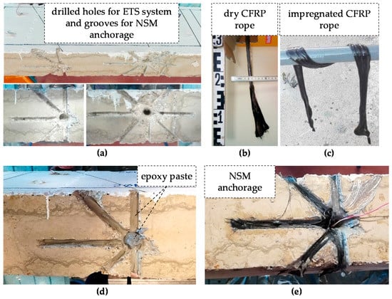
Figure 3.
Strengthening application stages of the rectangular beam: (a) drilled holes through the web and radial grooves at the top and the bottom of the beam; (b) carbon fibre-reinforced polymer (CFRP) rope before impregnation; (c) impregnation of the CFRP rope using impregnating resin; (d) filling of the drilled holes and the grooves of the anchorage region with a resin gun using epoxy paste; (e) insertion of the impregnated CFRP ropes inside the holes and anchorage of their free length inside the grooves using supplementary epoxy paste.
The examined NSM strengthening system is illustrated in Figure 4 and the application steps were: (1) 15-mm-diameter vertical holes were drilled through the depth of the slab, grooves of 15-mm width and 15-mm depth were opened on both lateral sides and on the width of the web, whereas radial square grooves were made at the top of the slab for the effective anchorage of the CFRP ropes (Figure 4a); an air compressor was used for dust cleaning of the grooves and the holes, which then were partially filled by epoxy resin injection using a resin gun (Figure 4b); (3) the 10-mm-diameter impregnated CFRP ropes were carefully installed into the grooves and inserted inside the drilled holes, whereas their free lengths were carefully anchored into the grooves using supplementary epoxy paste (Figure 4c); (4) extra epoxy paste was also used to seal the grooves and to fill them up the level of the beam surface (Figure 4d).
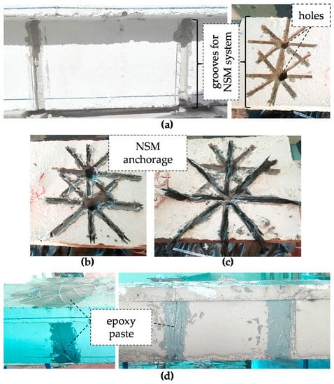
Figure 4.
Strengthening application stages of the T-shaped cross-section beam: (a) drilling holes through the slab and grooves at the top of the slab, the sides, and the bottom width of the web; (b) adhesive epoxy paste injected inside the slab holes and applied in the web grooves and the top slab grooves of the anchorage; (c) insertion of the impregnated CFRP ropes inside the slab holes and the web grooves and anchorage of their free length carefully inside the grooves using supplementary epoxy paste; (d) sealing and filling of the grooves with extra epoxy adhesive up to the level of the concrete surface.
The size of the grooves was designed considering the concrete cover and the available length of the cross-section of the tested beams, the Code provisions, and the test results of existing works concerning the anchorage of the FRP ropes. The clear concrete cover thickness of the tested beams was cnom = 20 mm, which defined the ultimate value of the depth and the width of the grooves. Further, according to the specifications of ACI 440.2R-08 [22] for NSM systems, the minimum dimensions of the grooves should not be less than 1.5 times the FRP bar diameter. Since the nominal diameter of the used impregnated CFRP rope was df = 10 mm, the width and the depth of the grooves had to be taken as dg = 1.5df = 15 mm < 20 mm (cnom). Furthermore, the anchorage embedded length of the free ends of the impregnated CFRP ropes was designed based on the available length, ℓav, which equalled: ℓav = (bw − dhole)/2 = 67.5 mm ≅ 7df (where bw is the web width of the beam that equals 150 mm and dhole is the 15-mm-diameter of the hole, as shown in Figure 5 for notation). The ultimate value of the anchorage length was taken as 2.5ℓav = 170 mm ≅ 17df, according to the test results of the specimens with sufficient bonded anchorage length of the CFRP ropes with similar size of grooves from the work of Kaya et al. [20].
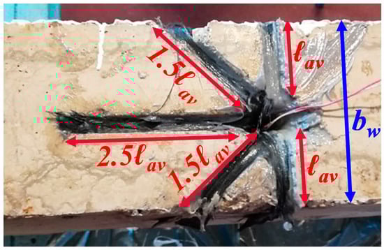
Figure 5.
Available and ultimate anchorage lengths of the CFRP ropes at the web width of the beam.
Further, it is noted that in the case of the ETS technique, the CFRP ropes were epoxied to a vertical direction or with shear-favourably inclination pre-drilled holes into the concrete, which provided greater confinement to the internal reinforcements by improving their bond performance. On the contrary, premature debonding failure of the CFRP ropes could be noted as the main disadvantage of the NSM technique, as the reinforcement relies on the concrete cover of the RC beams and the rather low capacity of concrete surface under tension limits the bonding strength between the CFRP ropes and the concrete. This technique can be efficient in cases when the concrete cover provides sufficient thickness for the grooves. Furthermore, the ETS system requires less preparation of the concrete than the NSM method.
Furthermore, in the recent work of Karayannis and Chalioris [23] it has been found that RC beams with shear-favourably inclined spiral shear reinforcements and rectangular shape exhibited enhanced post-peak response compared to beams with the same amount of vertical stirrups. Based on this finding, one vertical single-link and one shear-favourably inclined single-link CFRP rope was installed using the ETS system at each shear span of the rectangular beam “R-FRP”. This way, the favourable inclination of the CFRP rope to the imposed shear provided an obvious advantage, since this shear reinforcement was expected to normally cross the developed diagonal cracks. The benefit of the shear-favourably inclined CFRP rope with regards to the vertical one is examined herein.
2.3. Test Setup and Instrumentation
A typical four-point bending experimental setup was used for the tests as shown in Figure 6. The load was imposed in two points, 60 mm apart in the mid-span of the beams, by a 500 kN actuator. The tested specimens were simply edge-supported using roller supports. The length of the shear span and the span-to-depth ratio of the rectangular beams were α = 500 mm and α/d = 1.89, respectively, and for the flanged T-section beam, they were α = 400 mm and α/d = 1.51, respectively (typical deep beams).
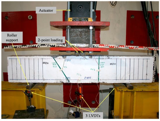
Figure 6.
Test rig and instrumentation.
The applied load was increased consistently at low rate and recorded using a load cell with 0.05 kN accuracy. Further, the deflections of the specimens were measured using three linear variable differential transducers (LVDTs); two of them with 0.01 mm and one with 0.005 mm accuracy. One LVDT was installed at the mid-span and two LVDTs were installed at the supports of each tested beam.
3. Test Results and Commentary
The overall behaviour of the beam specimens with rectangular and T-shaped cross-section is demonstrated in Figure 7 and Figure 8, respectively, in terms of applied load versus mid-span deflection curves (test data are also included in the Supplementary File 1: “Test-Data.xlsx”). The cracking patterns at failure of the tested beams are also illustrated in these Figures.
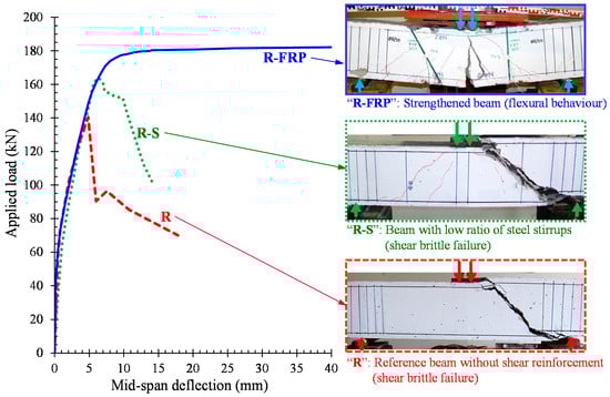
Figure 7.
Experimental response and cracking patterns at failure of the tested beams with rectangular cross-section.
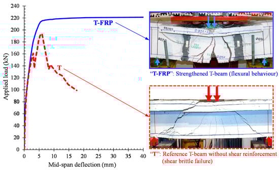
Figure 8.
Experimental behaviour and cracking patterns at failure of the tested beams with T-shaped cross-sections.
The reference specimens “R” and “T” without shear reinforcement and the beam “R-S” with a low ratio of stirrups, presented brittle shear failure, as expected. These beams failed upon the formation of one shear critical diagonal crack extended along the entire length of the shear span, which was a typical cracking performance for shear-critical deep beams. In the “R-S” beam, the shear failure occurred due to the yielding of the closed steel stirrup at higher level of the applied load.
On the contrary, the strengthened deep beams with CFRP ropes as the only transverse shear link reinforcement exhibited ductile flexural response with typical vertical cracks at the middle of the span, and less widely inclined shear cracks near the supports (see also the photographs of Figure 7 and Figure 8). The effective anchorage of the ropes at both beams improved the utilization of the strengthening material, and therefore these specimens demonstrated considerably higher capacity and enhanced post-peak response with respect to the strength and the brittle behaviour of the referenced beams. Neither damage-debonding failure at the anchorage region nor tensile rupture of the CFRP ropes occurred.
Regarding the overall performance of the strengthened specimens, the first vertical flexural cracks developed from the bottom surface at the mid-span of the beams (onset of flexural cracking). As the imposed loading increased, the cracks spread out and gradually less widely inclined cracks developed near the supports crossed by the CFRP ropes (onset of the shear cracking). Further increase of the applied load resulted in further widening of the flexural cracks at the mid-span without further widening of the inclined shear cracks, resulting in yielding of the longitudinal steel bars at the mid-span of the beams, and therefore to their flexural failure. After yielding of the longitudinal bars, the beams demonstrated significant ductility until failure.
It is obvious that the applied shear strengthening technique using CFRP ropes in both ETS and NSM systems was successful, since the fibre ropes as the only transverse link reinforcement increased the load-bearing capacity of the specimens and prevented their catastrophic brittle shear failure.
Further, the cracking pattern at failure of the shear strengthened rectangular beam “R-FRP” shown in Figure 7 reveals that the application of one vertical single-link and one shear-favourably inclined single-link CFRP rope at each shear span was related to the development of asymmetric diagonal cracking. The different inclination between the installed CFRP ropes caused shear cracks with different angles at each shear span.
The ultimate experimental applied load, Pu,exp, and the corresponding shear strength, Vu,exp, of the tested beam specimens, are summarised in Table 1.

Table 1.
Summary of the experimental and analytical results of the tested beams.
4. Analytical Predictions
An analytical approach to evaluate the shear strength of RC deep beams retrofitted using FRP ropes as strengthening shear reinforcement, is developed, and two models were implemented for the following (a) Rectangular RC deep beams strengthened in shear using FRP ropes in epoxy bonded pre-drilled holes as an ETS reinforcement, and (b) T-shaped flanged RC deep beams strengthened in shear using FRP ropes as a NSM reinforcement.
For the evaluation of the ETS and the NSM reinforcement contribution to the shear resistance of the beams, the analytical models proposed by Mofidi et al. [13], and by Paretti and Nanni [21], respectively, were been adopted and properly implemented in the proposed equation derived from the equilibrium of moments of forces acting on a deep beam at failure, as presented below and demonstrated in Figure 9, Figure 10 and Figure 11. The presented model was used to calculate the shear capacity of the examined beams. A summary of the analytical results is presented in Table 1.
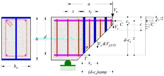
Figure 9.
Shear transfer mechanisms in a characteristic RC deep beam with rectangular cross-section, steel bars, and stirrups, which have been strengthened in shear using FRP ropes as a transverse link reinforcement using the embedded through section (ETS) system.
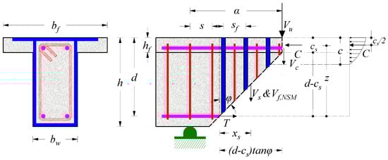
Figure 10.
Shear transfer mechanisms in a characteristic RC deep beam with T-shaped cross-section, steel bars and stirrups, which has been strengthened in shear using FRP ropes as transverse link reinforcement using the near surface-mounted (NSM) system.
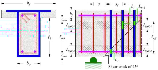
Figure 11.
Graphical representation of the variables used in the formulation.
4.1. Strengthened Beam with Rectangular Cross-Section
Figure 9 demonstrates the shear transfer mechanisms at the failure of a characteristic RC deep beam with a rectangular cross-section, and longitudinal and transverse steel reinforcements, which was also been strengthened in shear using FRP ropes as a transverse link reinforcement using the ETS system. It was considered that the shear forces were resisted by the contribution of the un-cracked concrete chord, Vc, the transverse steel reinforcement crossing the shear critical diagonal crack, Vs, and the contribution of the impregnated ETS FRP rope, Vf,ETS. Using the moment equilibrium equation of the internal forces acting on a deep beam at failure at the point of the concrete compression force application, C, the maximum shear strength, Vu, can be calculated by the following proposed expression:
where cs is the compression zone depth above the tip of the shear critical crack according to Zararis [24]; α is the shear span; bw and d are the web width and the effective depth of the cross-section, respectively; ρsw is the steel transverse reinforcement ratio; fyw is the yield tensile strength of the transverse steel reinforcement; xs is the distance of the shear force components of the transverse steel reinforcement, Vs, and of the strengthening FRP reinforcement, Vf,ETS, from the beginning of the shear crack and it is equal to the half of the horizontal projection of the shear crack.
Contribution of the FRP Ropes Using the ETS System
According to Mofidi et al. [13], the FRP contribution to the shear strength of RC beams strengthened in shear using ETS FRP ropes is given by the following expression:
where kL and ks are a decreasing coefficient and a parameter, respectively, which are described below; Af and Ef are the cross-sectional area and the modulus of elasticity of the impregnated FRP rope, respectively; dfv is the effective shear depth that equals to the greater of 0.72h and 0.9d (h and d are the height and the effective depth of the beam cross-section, respectively); θf is the inclination angle of the impregnated FRP rope with respect to the longitudinal axis of the beam; sf is the uniform spacing of the impregnated FRP ropes; εf is the effective strain in the principal direction of the fibres of the FRP rope. The effective strain is calculated as follows:
where df is the nominal diameter of the impregnated FRP rope; τm, sm and αb are bond parameters as described below.
The calculation of the effective strain of the impregnated FRP rope was based on the modified bond stress-slip model for FRP bars proposed by Cosenza et al. [25] and it depended on the bond parameters τm, sm, and αb derived from pull-out tests of epoxy bonded FRP ropes to pre-drilled holes inside concrete, where: τm is the maximum bond stress, sm is the slip at the maximum bond stress, and αb is a curve-fitting parameter that modifies the ascending branch of the bond stress-slip curve. Due to the lack of experimental data for the bond performance of the impregnated FRP ropes, the above bond parameters of ETS FRP reinforcement with the plain surface could be used for the evaluation of the effective strain of the ETS FRP ropes crossed by the shear critical crack. According to Godat et al. [26], the values of the bond parameters for FRP bars adopted in this study were derived as τm = 21.3 MPa, sm = 0.176 mm and αb = 0.125.
In addition, assuming that only tensile stresses were developed in the FRP ropes in the principal direction of the fibres, the tensile strain of the ropes could be evaluated by the strut-tie model. Therefore, the FRP ropes crossed by the shear critical crack were assumed to contribute equally to the FRP effective strain. Moreover, according to ACI 440.2R-08 [22], the effective strain of the FRP ropes should be limited to 0.4% in order to limit crack opening and to ensure appropriate interlock of concrete aggregate.
In expression (2), kL is a decreasing coefficient that ranges from 0 to 1. It represents the effect of FRP ropes with an anchorage length less than the minimum anchorage length required, Leff, given as:
where Leff is the effective length of the FRP rope that corresponds to the maximum slip, sm, beyond which the transferred stress shall not increase and depends on the tensile stress in the impregnated FRP rope at maximum slip, sm, given by the following expressions [25]:
Further, ks is a parameter that accounts for the effect of the internal shear steel reinforcement on the effective strain in the FRP ropes. Until further data are available, Mofidi et al. [13] recommend that ks can be equal to 0.6 for RC beams with internal steel reinforcement (stirrups) spacing less than 2/3d, whereas for RC beams without internal steel reinforcement or with stirrups spacing more than 2/3d, ks = 1.
4.2. Strengthened Flanged Beam with T-Shaped Cross-Section
In Figure 10, the shear transfer mechanisms at failure of a characteristic RC deep beam with a T-shaped cross-section, and longitudinal and transverse steel reinforcement, which were also strengthened in shear using FRP ropes as transverse link reinforcement using the NSM system. In the case of the flanged T-shaped beams, the width of the compression zone and, consequently, the width of the area contributed to the shear strength of a beam did not remain constant, but it changed from the width of the web, bw to the flange width, bf. For this reason, an effective flange width, bef, was taken into account to evaluate the ultimate shear strength of T-section beams and this is given by the following expression according to Zararis et al. [27]:
where c is the neutral axis depth; hf and bf are the height and the width of the flange, respectively.
Therefore, for the case of a T-shaped deep RC beam strengthened in shear using FRP ropes with NSM system and using the moment equilibrium of the internal forces at failure at the point of the concrete compression force application, C, the maximum shear strength, Vu, can be calculated using the following proposed expression (see also Figure 10 for notation):
where Vf,NSM is the shear force component of the strengthening NSM FRP reinforcement; cs is the depth of the compression zone above the tip of the shear critical crack]; α is the shear span of the beam; bw and d are the web width and the effective depth of the cross-section, respectively; ρsw and fyw are the ratio and the yield tensile strength of the transverse steel reinforcement, respectively.
Figure 9 and Figure 10 also demonstrate the shear transfer mechanisms in RC deep beams with rectangular and T-shaped cross-sections at failure. In a typical RC deep beam, the failure occurred due to crushing of concrete at the top of the shear critical crack. Assuming that failure was due to the exceedance of the concrete compressive strength, fc, by the developed stress at the compression zone above the tip of the shear critical crack, cs, the compressive force of concrete at failure is given by the following proposed expressions:
Further, the calculation of the shear force resisted by the steel transverse reinforcement crossed by the shear critical crack is proposed as follows:
where for RC deep beams (see also Figure 9 and Figure 10).
Taking the equilibrium of forces in the direction of the beam longitudinal axis, T = C, and the equilibrium of moments of the forces acting on a deep beam at failure at the point of the concrete compression force application, expressions (1) and (7) were derived for the calculation of the shear capacity, Vu, of RC deep beams with rectangular and T-shaped cross-section, respectively.
Contribution of the FRP Ropes Using the NSM System
According to Paretti and Nanni [21], the shear strength provided by the NSM reinforcement is the force resulting from the tensile stress in the impregnated FRP ropes crossed by a 45° shear crack, and it is expressed using the following expression:
where τb is the average bond stress of the FRP ropes crossed by the shear diagonal crack. According to ACI 440.2R-08 [22], a conservative value of 6.9 MPa as the average bond stress between FRP and concrete can be used.
Ltot can be expressed as the sum of Li, , where Li represents the length of each single NSM reinforcement crossed by a 45° shear crack (see Figure 11), and it is calculated as follows:
In expression (12), ℓnet is defined as:
which represents the net length of the FRP ropes (see also Figure 11), taking into account the concrete cover cracking and the installation tolerances. It is noted that ℓb in the above expression is the actual length of the FRP rope and cnom is the thickness of the clear concrete cover.
The first limitation in expression (12) considers that bond failure occurs and represents the minimum effective length of the FRP rope crossed by the shear critical crack depending on the term:
where n is rounded off to the lowest integer and ℓeff is the vertical projection of ℓnet (see also Figure 11):
The second limitation in expression (12) considers the shear integrity of concrete, taking into account an upper limit value for the effective strain of the FRP reinforcement equal to 0.4%. Further based on the force equilibrium condition: , the value of ℓ0.004 can be determined as follows [22]:
4.3. Prediction of the Expected Failure Mode
The aforementioned analytical models are used for the calculation of the shear capacity of the strengthened beams with rectangular and T-shaped cross-sections using FRP ropes as ETS and NSM additional reinforcement, respectively. However, a reliable approach should include a holistic analysis that describes the possible failure modes of the examined beams in order to predict the weakest link chain of resistance of a structural member [28]. Thus, the flexural strength of the tested beams at yield and at ultimate has also been evaluated using common sectional analysis of steel RC beams under bending moment, as presented in Table 1. This way, the ultimate load bearing capacity of the beams is determined as the minimum value, or else the weakest link chain of resistance, of the calculated strength corresponding to the flexural and to the shear capacity. Based on this consideration, the predicted failure mode of the beams is also displayed in Table 1.
The predicted failure modes of each beam presented in Table 1 reveal that both the strengthened beams “R-FRP” and “T-FRP” are expected to fail due to flexure (failure mode denoted as “Fl”), since their calculated total strength corresponding to the ultimate flexural strength, PMu,calc, is lower than the calculated total strength corresponding to the ultimate shear strength, PVu,calc, or else: PMu,calc < PVu,calc → flexural failure “Fl” is expected. It is noted that based on the loading scheme of the performed tests (see also Figure 1, Figure 2 and Figure 5), it is deduced that:
where My,calc is the flexural strength at yielding of the longitudinal reinforcement calculated by common sectional analysis of steel RC beams under bending moment, Mu,calc is the ultimate flexural strength, also calculated by common sectional analysis of steel RC beams under bending moment, α is the shear span, and VVu,calc is the ultimate shear strength calculated using the developed analytical approach.
On the contrary, the reference non-strengthened beams “R”, “R-S” and “T” are expected to fail due to shear. Especially, the rectangular beams “R” and “R-S” are expected to fail due to shear brittle failure (failure mode denoted as “Sh”) since their calculated total strength corresponding to the ultimate shear strength, PVu,calc, is lower than the calculated total strength corresponding to the flexural strength at yielding of the longitudinal reinforcement, PMy,calc, or else: PVu,calc < PMy,calc → shear brittle failure “Sh” is expected. A slight modification appears in the case of the T-shaped beam “T” because this beam is expected to fail due to shear failure after yielding of the tensional bars (failure mode denoted as “SY”) since its calculated total strength corresponding to the ultimate shear strength, PVu,calc (=226.4 kN), is slightly greater than the calculated total strength corresponding to the flexural strength at yielding of the longitudinal reinforcement, PMy,calc (=224.0 kN), but lower than the calculated total strength corresponding to the ultimate flexural strength, PMu,calc (=234.0 kN), or else: PMy,calc < PVu,calc < PMu,calc → shear failure after yielding of the tensional bars “SY” is expected.
From the comparison of the experimentally obtained and the analytically predicted failure modes presented in Table 1 it is deduced that in all the examined cases, very good agreement has been achieved.
5. Concluding Remarks
An innovative shear strengthening technique for deficient reinforced concrete (RC) deep beams without, or with inadequate stirrups using carbon fibre-reinforced polymer (CFRP) ropes as the only, or additional transverse shear link reinforcement is proposed and experimentally investigated. For the application of the CFRP, the embedded through-section (ETS) and the near-surface-mounted (NSM) systems have been examined in shear-critical beams with rectangular and T-shaped cross-sections, respectively. Promising preliminary test results have been derived concerning the applied strengthening technique, since the beams with CFRP ropes exhibited increased capacity and significantly improved overall behaviour with regards to the reference beams. It is stressed that the application of the CFRP ropes prevented the catastrophic brittle failure of the beams by altering the shear failure to a ductile flexural one. However, more tests are needed to establish the effectiveness of the proposed shear strengthening technique, to thoroughly examine the parameters that influence the overall structural response and to derive sound conclusions. An analytical approach has also been presented to predict the shear strength of deep beams strengthened in shear using FRP ropes as a transverse link reinforcement, and a satisfactory agreement with the test results has been achieved.
Supplementary Materials
The test data curves of the beams and concrete strength details are available online at http://www.mdpi.com/2079-6439/6/3/52/s1, excel file: Supplementary File 1: “Test-Data.xlsx”.
Author Contributions
All authors contributed extensively to the presented study, discussed the results and reviews, and agreed to the modifications at all stages of the paper. C.E.C. and P.-M.K.K. prepared the manuscript. N.A.P. constructed the beam specimens and conducted the tests under the supervision of C.E.C. who designed the experiments. P.-M.K.K. developed the aspects of the analytical model under the supervision of C.E.C.
Funding
This research received no external funding.
Acknowledgments
The authors wish to thank SIKA Hellas for supplying the CFRP reinforcements and filling materials (impregnating resin and epoxy paste), in particular Nikos Anagnostopoulos for his advice and support in the strengthening application of the tested beams.
Conflicts of Interest
The authors declare no conflict of interest.
Glossary/Nomenclature/Abbreviations
| Af | cross-sectional area of the impregnated fibre-reinforced polymer (FRP) rope (mm2) |
| Asw | cross-sectional area of the steel transverse reinforcement (mm2) |
| bef | effective flange width (mm) |
| bf | flange width of the T-shaped cross-section (mm) |
| bw | web width of the T-shaped cross-section (mm) |
| C | concrete compression force (kN) |
| c | neutral axis depth (mm) |
| cnom | clear concrete cover thickness (mm) |
| cs | depth of the compression zone above the tip of the shear critical crack (mm) |
| d | effective depth of the cross-section (mm) |
| df | nominal diameter of the impregnated FRP rope (mm) |
| dfv | effective shear depth (the greater of 0.72h and 0.9d) (mm) |
| Ef | modulus of elasticity of the impregnated FRP rope (GPa) |
| fc | cylinder compressive strength of concrete (MPa) |
| fyw | yield tensile strength of the transverse steel reinforcement (MPa) |
| h | height of the cross-section (mm) |
| hf | height of the flange of the T-shaped cross-section (mm) |
| My,calc | flexural strength at yielding of the longitudinal reinforcement (kNm) |
| Mu,calc | ultimate flexural strength (kNm) |
| s | uniform spacing of the steel transverse shear reinforcement (mm) |
| sf | uniform spacing of the impregnated FRP ropes (mm) |
| T | normal tension force of the longitudinal reinforcement (kN) |
| PMy,calc | calculated total strength corresponding to the flexural strength at yielding of the longitudinal reinforcement (kN) |
| PMu,calc | calculated total strength corresponding to the ultimate flexural strength (kN) |
| VVu,calc | ultimate shear strength (kN) |
| Vu,exp | experimental shear strength (kN) |
| PVu,calc | calculated total strength corresponding to the ultimate shear strength (kN) |
| Pu,exp | ultimate experimental applied load (kN) |
| z | lever arm (mm) |
| α | shear span (mm) |
| αb | bond parameter derived from pull-out tests and defined by Cosenza et al. [25] |
| εf | effective strain in the principal direction of the fibres of the FRP rope (%) |
| θf | inclination angle of the impregnated FRP rope with respect to the beam longitudinal axis (deg) |
| ρsw | steel transverse reinforcement ratio equal to Asw/bws (%) |
| φ | inclination angle of the shear critical crack (deg) |
References
- Karayannis, C.G.; Chalioris, C.E. Experimental investigation of the contribution of bonded C-FRP jackets to shear capacity of RC beams. In Proceedings of the International Symposium Celebrating Concrete: People and Practice, Dundee, UK, 3–4 September 2003; pp. 689–696. [Google Scholar]
- Bencardino, F.; Spadea, G.; Swamy, R.N. The problem of shear in RC beams strengthened with CFRP laminates. Constr. Build. Mater. 2007, 21, 1997–2006. [Google Scholar] [CrossRef]
- Karayannis, C.G.; Sirkelis, G.M. Strengthening and rehabilitation of RC beam-column joints using carbon-FRP jacketing and epoxy resin injection. Earthq. Eng. Struct. Dyn. 2008, 37, 769–790. [Google Scholar] [CrossRef]
- Tsonos, A.G. Effectiveness of CFRP-jackets and RC-jackets in post-earthquake and pre-earthquake retrofitting of beam-column subassemblages. Eng. Struct. 2008, 30, 777–793. [Google Scholar] [CrossRef]
- Ombres, L. Structural performances of reinforced concrete beams strengthened in shear with a cement based fiber composite material. Compos. Struct. 2015, 122, 316–329. [Google Scholar] [CrossRef]
- Barros, J.A.O.; Dias, S.J.E. Assessment of the effectiveness of the NSM shear strengthening technique for deep T cross section RC beams. In Proceedings of the 11th International Symposium on Fiber Reinforced Polymers for Reinforced Concrete Structures FRPRCS11, Guimarães, Portugal, 26–28 June 2013. [Google Scholar]
- Seo, S.-Y.; Feo, L.; Hui, D. Bond strength of near surface-mounted FRP plate for retrofit of concrete structures. Compos. Struct. 2013, 95, 719–727. [Google Scholar] [CrossRef]
- De Lorenzis, L.; Nanni, A. Shear strengthening of reinforced concrete beams with near-surface mounted fiber-reinforced polymer rods. ACI Struct. J. 2001, 98, 60–68. [Google Scholar]
- Bilotta, A.; Ceroni, F.; Di Ludovico, M.; Nigro, E.; Pecce, M.; Manfredi, G. Bond efficiency of EBR and NSM FRP systems for strengthening concrete members. ASCE J. Compos. Constr. 2011, 15, 757–772. [Google Scholar] [CrossRef]
- Parvin, A.; Syed Shah, T. Fiber Reinforced Polymer Strengthening of Structures by Near-Surface Mounting Method. Polymers 2016, 8, 298. [Google Scholar] [CrossRef]
- Oehlers, D.J.; Haskett, M.; Wu, C.; Seracino, R. Embedding NSM FRP plates for improved IC debonding resistance. ASCE J. Compos. Constr. 2008, 12, 635–642. [Google Scholar] [CrossRef]
- Breveglieri, M.; Aprile, A.; Barros, J.A.O. Embedded through-section shear strengthening technique using steel and CFRP bars in RC beams of different percentage of existing stirrups. Compos. Struct. 2015, 126, 101–113. [Google Scholar] [CrossRef]
- Mofidi, A.; Chaallal, O.; Benmokrane, B.; Neale, K. Experimental tests and design model for RC beams strengthened in shear using the embedded through-section FRP method. ASCE J. Compos. Constr. 2012, 16, 540–550. [Google Scholar] [CrossRef]
- Breveglieri, M.; Aprile, A.; Barros, J.A.O. Embedded through-section shear strengthening technique using steel bars. Eng. Struct. 2014, 81, 76–87. [Google Scholar] [CrossRef]
- Chaallal, O.; Mofidi, A.; Benmokrane, B.; Neale, K. Embedded through-section FRP rod method for shear strengthening of RC beams: Performance and comparison with existing techniques. J. Compos. Constr. 2011, 15, 374–383. [Google Scholar] [CrossRef]
- Yang, K.H.; Byun, H.Y.; Ashour, A.F. Shear strengthening of continuous reinforced concrete T-beams using wire rope units. Eng. Struct. 2009, 31, 1154–1165. [Google Scholar] [CrossRef]
- Chalioris, C.E.; Papadopoulos, N.A.; Panagiotopoulos, T.A.; Kosmidou, P.-Μ.K. Shear strengthening of reinforced concrete deep beams without stirrups using carbon fibre rope as transverse link reinforcement. In Proceedings of the 12th Annual International Conference on Composites/Nano Engineering ICCE-25, Rome, Italy, 16–22 July 2017. [Google Scholar]
- Rousakis, T.C. Hybrid confinement of concrete by Fiber-Reinforced Polymer sheets and fiber ropes under cyclic axial compressive loading. ASCE J. Compos. Constr. 2013, 17, 732–743. [Google Scholar] [CrossRef]
- El-Saikaly, G.; Godat, A.; Chaallal, O. New anchorage technique for FRP shear-strengthened RC T-beams using CFRP rope. ASCE J. Compos. Constr. 2015, 19. [Google Scholar] [CrossRef]
- Kaya, E.; Kütan, C.; Sheikh, S.; İlki, A. Flexural retrofit of support regions of reinforced concrete beams with anchored FRP ropes using NSM and ETS methods under reversed cyclic loading. ASCE J. Compos. Constr. 2017, 21, 1574–1582. [Google Scholar] [CrossRef]
- Parretti, R.; Nanni, R. Strengthening of RC members using near-surface mounted FRP composites: Design overview. Adv. Struct. Eng. 2004, 7, 469–483. [Google Scholar] [CrossRef]
- ACI (American Concrete Institute). Guide for the Design and Construction of Externally Bonded FRP Systems for Strengthening Concrete Structures; ACI-440.2R-08; American Concrete Institute (ACI): Farmington Hills, MI, USA, 2008; p. 76. [Google Scholar]
- Karayannis, C.G.; Chalioris, C.E. Shear tests of reinforced concrete beams with continuous rectangular spiral reinforcement. Constr. Build. Mater. 2013, 46, 86–97. [Google Scholar] [CrossRef]
- Zararis, P.D. Shear compression failure in reinforced concrete deep beams. ASCE J. Struct. Eng. 2003, 129, 544–553. [Google Scholar] [CrossRef]
- Cosenza, E.; Manfredi, G.; Realfonzo, R. Development length of FRP straight rebars. Compos. Part B 2002, 33, 493–504. [Google Scholar] [CrossRef]
- Godat, A.; L’Hady, A.; Chaallal, O.; Neale, K.W. Bond Behavior of the ETS FRP Bar shear-strengthening method. ASCE J. Compos. Constr. 2012, 16, 529–539. [Google Scholar] [CrossRef]
- Zararis, I.P.; Karaveziroglou, M.K.; Zararis, P.D. Shear strength of reinforced concrete T-beams. ACI Struct. J. 2006, 103, 693–700. [Google Scholar]
- Bencardino, F.; Colotti, V.; Spadea, G.; Swamy, R.N. Holistic design of RC beams and slabs strengthened with externally bonded FRP laminates. Cem. Concr. Compos. 2006, 28, 832–844. [Google Scholar] [CrossRef]


© 2018 by the authors. Licensee MDPI, Basel, Switzerland. This article is an open access article distributed under the terms and conditions of the Creative Commons Attribution (CC BY) license (http://creativecommons.org/licenses/by/4.0/).