Investigation of Transcrystalline Interphases in Polypropylene/Glass Fiber Composites Using Micromechanical Tests

Abstract
:1. Introduction
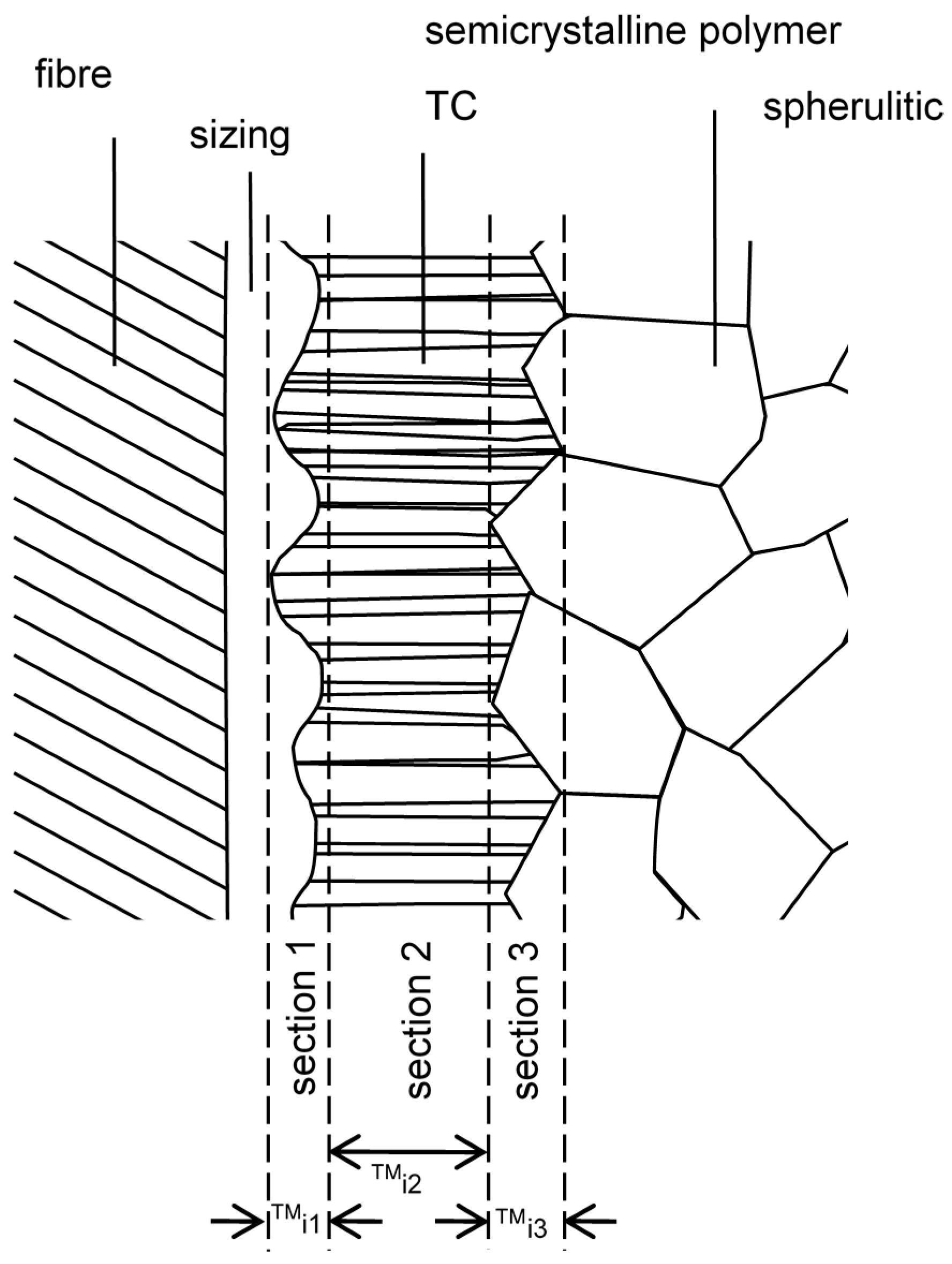
1.1. Structure of the TC Interphase
1.2. The TC Interphase and Its Impact on the Micromechanics and Composite Properties
2. Experimental
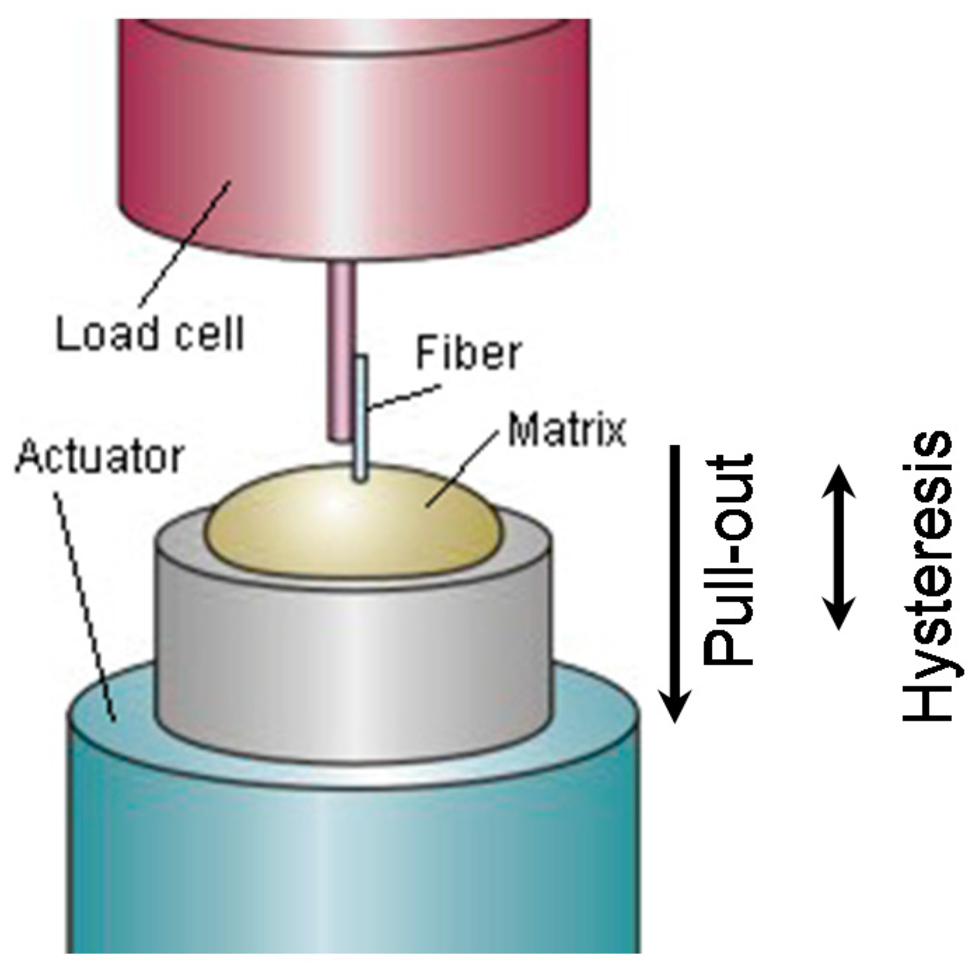
2.1. Methods
2.2. Materials
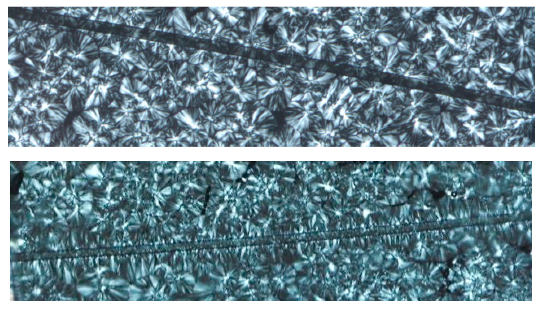
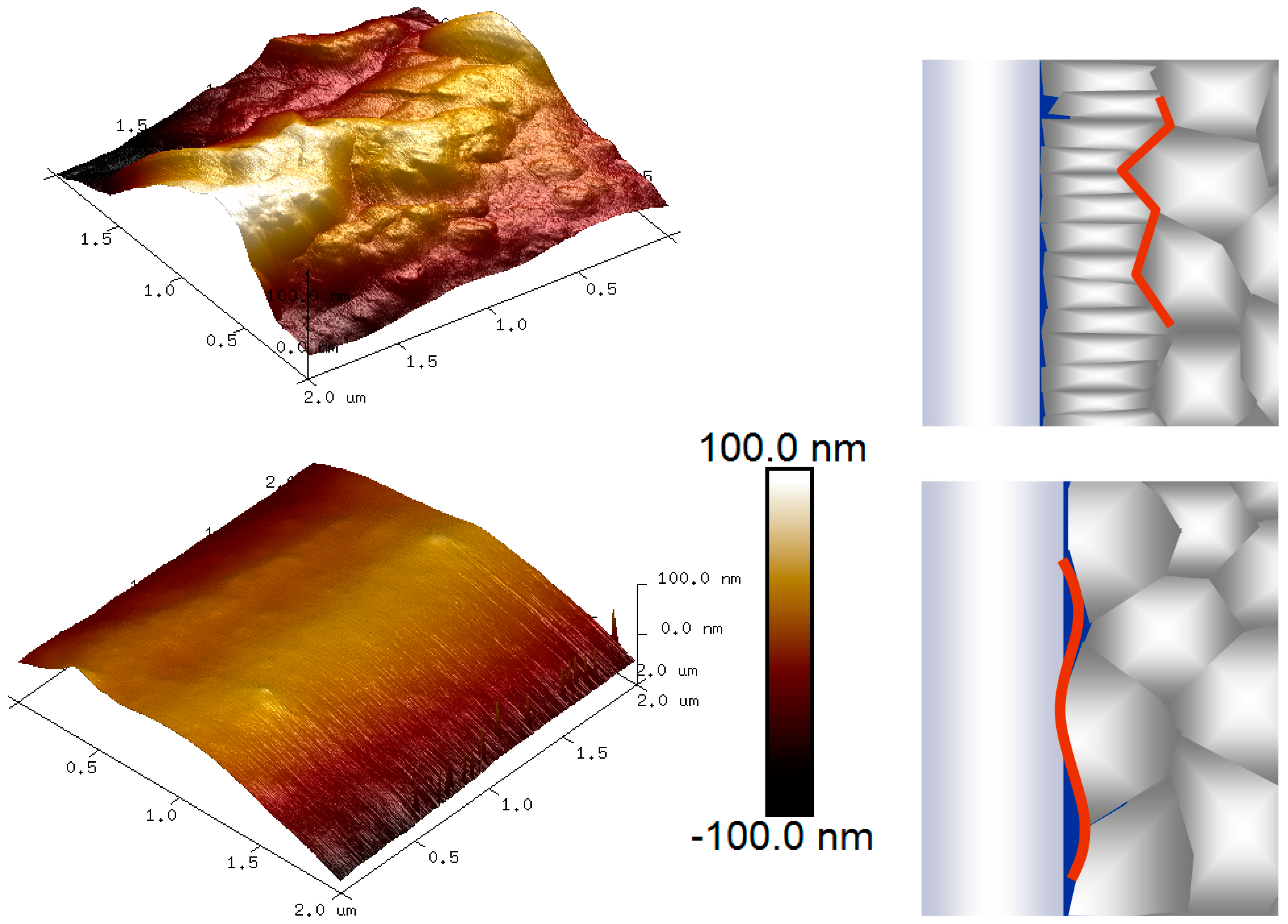
3. Results
4. Conclusions
Acknowledgments
Author Contributions
Conflicts of Interest
References
- Ishida, H.; Bussi, P. Surface induced crystallization in ultrahigh-modulus polyethylene fiber-reinforced polyethylene composites. Macromolecules 1991, 24, 3569–3577. [Google Scholar] [CrossRef]
- Billon, N.; Magnet, C.; Haudin, J.; Lefebvre, D. Transcrystallinity effects in thin polymer films. Experimental and theoretical approach. Colloid Polym. Sci. 1994, 272, 633–654. [Google Scholar] [CrossRef]
- Wu, C.-M.; Chen, M.; Karger-Kocsis, J. Transcrystallization in syndiotactic polypropylene induced by high-modulus carbon fibers. Polym. Bull. 1998, 41, 239–245. [Google Scholar] [CrossRef]
- Thomason, J.; Van Rooyen, A. Transcrystallized interphase in thermoplastic composites. J. Mater. Sci. 1992, 27, 897–907. [Google Scholar] [CrossRef]
- Wang, C.; Liu, C.-R. Transcrystallization of polypropylene composites: Nucleating ability of fibers. Polymer 1999, 40, 289–298. [Google Scholar] [CrossRef]
- Thomason, J.; Van Rooyen, A. The transcrystallised interphase in thermoplastic composites. In Controlled Interphases in Composite Materials; Springer: Dordrecht, The Netherlands, 1990; pp. 423–430. [Google Scholar]
- Wang, C.; Hwang, L. Transcrystallization of ptfe fiber/pp composites (I) crystallization kinetics and morphology. J. Polym. Sci. Part B Polym. Phys. 1996, 34, 47–56. [Google Scholar] [CrossRef]
- Wang, C.; Hwang, L. Transcrystallization of ptfe fiber/pp composites. II. Effect of transcrystallinity on the interfacial strength. J. Polym. Sci. Part B Polym. Phys. 1996, 34, 1435–1442. [Google Scholar] [CrossRef]
- Assouline, E.; Pohl, S.; Fulchiron, R.; Gerard, J.-F.; Lustiger, A.; Wagner, H.; Marom, G. The kinetics of α and β transcrystallization in fiber-reinforced polypropylene. Polymer 2000, 41, 7843–7854. [Google Scholar] [CrossRef]
- Jenckel, E.; Teege, E.; Hinrichs, W. Transkristallisation in hochmolekularen stoffen. Colloid Polym. Sci. 1952, 129, 19–24. [Google Scholar] [CrossRef]
- Bessell, T.; Hull, D.; Shortall, J.B. Interface morphology and mechanical properties of unidirectional fiber reinforced nylon 6. Faraday Spec. Discuss. Chem. Soc. 1972, 2, 137–143. [Google Scholar] [CrossRef]
- Raimo, M. On the origin of transcrystalline morphology in polymers and their composites: Re-evaluation of different views. Mater. Today Commun. 2015, 3, 137–140. [Google Scholar] [CrossRef]
- Varga, J.; Karger-Kocsis, J. The occurence of transcrystallization or row-nucleated cylindritic crystallization as a result of shearing in a glass-fiber-reinforced polypropylene. Compos. Sci. Technol. 1993, 48, 191–198. [Google Scholar] [CrossRef]
- Feldman, A.; Gonzalez, M.F.; Marom, G. Transcrystallinity in surface modified aramid fiber reinforced nylon 66 composites. Macromol. Mater. Eng. 2003, 288, 861–866. [Google Scholar] [CrossRef]
- Clark, R.L.; Kander, R.G.; Sauer, B.B. Nylon 66/poly (vinyl pyrrolidone) reinforced composites: 1. Interphase microstructure and evaluation of fiber–matrix adhesion. Compos. Part A Appl. Sci. Manuf. 1999, 30, 27–36. [Google Scholar] [CrossRef]
- Clark, R.L.; Craven, M.D.; Kander, R.G. Nylon 66/poly (vinyl pyrrolidone) reinforced composites: 2: Bulk mechanical properties and moisture effects. Compos. Part A Appl. Sci. Manuf. 1999, 30, 37–48. [Google Scholar] [CrossRef]
- Levitus, D.; Kenig, S.; Kazanci, M.; Harel, H.; Marom, G. Effect of transcrystalline interface on the mechanical properties of polyethylene/polyethylene composites. Adv. Compos. Lett. 2001, 10, 61–65. [Google Scholar]
- Chou, S.; Chen, S.-H. Effect of high temperature nucleating agent on adhesion of glass fibers to nylon 6-6. Polym. Polym. Compos. 2000, 8, 333–343. [Google Scholar]
- Clark, R.; Kander, R.; Srinivas, S. Morphological changes in polyamide/pvp blends. Polymer 1998, 39, 507–516. [Google Scholar] [CrossRef]
- Pompe, G.; Mäder, E. Experimental detection of a transcrystalline interphase in glass-fiber/polypropylene composites. Compos. Sci. Technol. 2000, 60, 2159–2167. [Google Scholar] [CrossRef]
- Assouline, E.; Wachtel, E.; Grigull, S.; Lustiger, A.; Wagner, H.; Marom, G. Lamellar orientation in transcrystalline γ isotactic polypropylene nucleated on aramid fibers. Macromolecules 2002, 35, 403–409. [Google Scholar] [CrossRef]
- Shi, H.; Zhao, Y.; Dong, X.; He, C.; Wang, D.; Xu, D. Transcrystalline morphology of nylon 6 on the surface of aramid fibers. Polym. Int. 2004, 53, 1672–1676. [Google Scholar] [CrossRef]
- Hoffman, J.D.; Miller, R.L. Kinetic of crystallization from the melt and chain folding in polyethylene fractions revisited: Theory and experiment. Polymer 1997, 38, 3151–3212. [Google Scholar] [CrossRef]
- Strobl, G. A new approach to polymer crystallization used in an analysis of data of syndiotactic polypropylene. Acta Polym. 1997, 48, 562–570. [Google Scholar] [CrossRef]
- Schoolenberg, G.; Van Rooyen, A. Transcrystallinity in fiber-reinforced thermoplastic composites. Compos. Interfaces 1993, 1, 243–252. [Google Scholar]
- Beehag, A.; Ye, L. Fiber/Matrix Adhesion in Thermoplastic Composite: Is Transcrystallinity a Key. In Proceedings of the Eleventh International Conference Composite Materials (ICCM-11), Gold Coast, Australia, 14–18 July 1997; pp. 723–730. [Google Scholar]
- Wu, C.-M.; Chen, M.; Karger-Kocsis, J. Micromorphologic feature of the crystallization of isotactic polypropylene after melt-shearing. Polym. Bull. 1998, 41, 493–499. [Google Scholar] [CrossRef]
- Varga, J.; Karger-Kocsis, J. Interfacial morphologies in carbon fiber-reinforced polypropylene microcomposites. Polymer 1995, 36, 4877–4881. [Google Scholar] [CrossRef]
- Cartledge, H.C.; Baillie, C.A. Studies of microstructural and mechanical properties of nylon/glass composite part i the effect of thermal processing on crystallinity, transcrystallinity and crystal phases. J. Mater. Sci. 1999, 34, 5099–5111. [Google Scholar] [CrossRef]
- Chen, E.J.; Hsiao, B.S. The effects of transcrystalline interphase in advanced polymer composites. Polym. Eng. Sci. 1992, 32, 280–286. [Google Scholar] [CrossRef]
- Huson, M.; McGill, W. The effect of transcrystallinity on the behavior of fibers in polymer matrices. J. Polym. Sci. Part B Polym. Phys. 1985, 23, 121–128. [Google Scholar] [CrossRef]
- Wagner, H.; Lustiger, A.; Marzinsky, C.; Mueller, R. Interlamellar failure at transcrystalline interfaces in glass/polypropylene composites. Compos. Sci. Technol. 1993, 48, 181–184. [Google Scholar] [CrossRef]
- Cartledge, H.C.; Baillie, C.A. Studies of microstructural and mechanical properties of nylon/glass composite part ii the effect of microstructures on mechanical and interfacial properties. J. Mater. Sci. 1999, 34, 5113–5126. [Google Scholar] [CrossRef]
- Folkes, M.; Wong, W. Determination of interfacial shear strength in fiber-reinforced thermoplastic composites. Polymer 1987, 28, 1309–1314. [Google Scholar] [CrossRef]
- Rolel, D.; Yavin, E.; Wachtel, E.; Wagner, H. Experimental study of transcrystallinity in uhmwpe/lldpe composites. Compos. Interfaces 1993, 1, 225–242. [Google Scholar]
- Carvalho, W.S.; Bretas, R.E. Thermoplastic/carbon fiber composites: Correlation between interphase morphology and dynamic mechanical properties. Eur. Polym. J. 1990, 26, 817–821. [Google Scholar] [CrossRef]
- Lopez-Manchado, M.; Arroyo, M. Crystallization kinetics of polypropylene part 4: Effect of unmodified and azide-modified pet and pa short fibers. Polymer 1999, 40, 487–495. [Google Scholar] [CrossRef]
- Klein, N.; Marom, G.; Pegoretti, A.; Migliaresi, C. Determining the role of interfacial transcrystallinity in composite materials by dynamic mechanical thermal analysis. Composites 1995, 26, 707–712. [Google Scholar] [CrossRef]
- Karger-Kocsis, J. Interphase with lamellar interlocking and amorphous adherent—A model to explain effects of transcrystallinity. Adv. Compos. Lett. 2000, 9, 225–230. [Google Scholar]
- Gao, S.-L.; Mäder, E. Characterisation of interphase nanoscale property variations in glass fiber reinforced polypropylene and epoxy resin composites. Compos. Part A Appl. Sci. Manuf. 2002, 33, 559–576. [Google Scholar] [CrossRef]
- Folkes, M.; Hardwick, S. Direct study of the structure and properties of transcrystalline layers. J. Mater. Sci. Lett. 1987, 6, 656–658. [Google Scholar] [CrossRef]
- Assouline, E.; Grigull, S.; Marom, G.; Wachtel, E.; Wagner, H. Morphology of α-transcrystalline isotactic polypropylene under tensile stress studied with synchrotron microbeam X-ray diffraction. J. Polym. Sci. Part B Polym. Phys. 2001, 39, 2016–2021. [Google Scholar] [CrossRef]
- Schultz, J.; Nardin, M. Interfacial adhesion, interphase formation and mechanical properties of single fiber polymer-based composites. In Controlled Interphases in Composite Materials; Springer: Dordrecht, The Netherlands, 1990; pp. 561–567. [Google Scholar]
- Teishev, A.; Marom, G. The effect of transcrystallinity on the transverse mechanical properties of single-polymer polyethylene composites. J. Appl. Polym. Sci. 1995, 56, 959–966. [Google Scholar] [CrossRef]
- Folkes, M.; Hardwick, S. The mechanical properties of glass/polypropylene multilayer laminates. J. Mater. Sci. 1990, 25, 2598–2606. [Google Scholar] [CrossRef]
- Mäder, E.; Grundke, K.; Jacobasch, H.-J.; Wachinger, G. Surface, interphase and composite property relations in fiber-reinforced polymers. Composites 1994, 25, 739–744. [Google Scholar] [CrossRef]
- Zhandarov, S.; Mäder, E. Characterization of fiber/matrix interface strength: Applicability of different tests, approaches and parameters. Compos. Sci. Technol. 2005, 65, 149–160. [Google Scholar] [CrossRef]
- Mäder, E.; Mörschel, U.; Effing, M. Quality assessment of composites. JEC Compos. Mag. 2016, 102, 49–51. [Google Scholar]
- Brodowsky, H.M.; Jenschke, W.; Mäder, E. Characterization of interphase properties: Microfatigue of single fiber model composites. Compos. Part A Appl. Sci. Manuf. 2010, 41, 1579–1586. [Google Scholar] [CrossRef]
- Mäder, E.; Gao, S.-L.; Plonka, R.; Wang, J. Investigation on adhesion, interphases, and failure behavior of cyclic butylene terephthalate (cbt®)/glass fiber composites. Compos. Sci. Technol. 2007, 67, 3140–3150. [Google Scholar] [CrossRef]
- Brodowsky, H.M.; Jenschke, W.; Mäder, E. Characterization of interphase properties by frequency-dependent cyclic loading of single fiber model composites. J. Adhes. Sci. Technol. 2010, 24, 237–253. [Google Scholar] [CrossRef]


| PP HD 120 hiMW | PP HH450 loMW | ||||||
|---|---|---|---|---|---|---|---|
| E (GPa) | σm (MPa) | acU (J/m²) | E (GPa) | σm (MPa) | acU (J/m²) | ||
| 0.5% MaPP | APS-PP TC | 6100 | 79 | 38 | 4900 | 68 | 21 |
| APS-PU Non-TC | 5700 | 37 | 16 | 5400 | 38 | 17 | |
| no fiber | 1250 | 27 | 142 | 1300 | 27 | 121 | |
| 2% MaPP | APS-PP TC | 6500 | 93 | 55 | 5800 | 87 | 55 |
| APS-PU non-TC | 6200 | 83 | 44 | 6100 | 83 | 44 | |
| no fiber | 1500 | 107 | 1300 | 87 | |||
| Sizing | τd | Gic | τf | |
|---|---|---|---|---|
| HH450 | APS-PU | 9.0 | 3.0 | 4.4 |
| APS-PP | 15.7 | 8.3 | 6.1 | |
| HD120 | APS-PU | 10.0 | 3.4 | 5.4 |
| APS-PP | 13.4 | 7.0 | 6.4 |
© 2018 by the authors. Licensee MDPI, Basel, Switzerland. This article is an open access article distributed under the terms and conditions of the Creative Commons Attribution (CC BY) license (http://creativecommons.org/licenses/by/4.0/).
Share and Cite
Brodowsky, H.; Mäder, E. Investigation of Transcrystalline Interphases in Polypropylene/Glass Fiber Composites Using Micromechanical Tests. Fibers 2018, 6, 16. https://doi.org/10.3390/fib6010016
Brodowsky H, Mäder E. Investigation of Transcrystalline Interphases in Polypropylene/Glass Fiber Composites Using Micromechanical Tests. Fibers. 2018; 6(1):16. https://doi.org/10.3390/fib6010016
Chicago/Turabian StyleBrodowsky, Hanna, and Edith Mäder. 2018. "Investigation of Transcrystalline Interphases in Polypropylene/Glass Fiber Composites Using Micromechanical Tests" Fibers 6, no. 1: 16. https://doi.org/10.3390/fib6010016
APA StyleBrodowsky, H., & Mäder, E. (2018). Investigation of Transcrystalline Interphases in Polypropylene/Glass Fiber Composites Using Micromechanical Tests. Fibers, 6(1), 16. https://doi.org/10.3390/fib6010016