1. Introduction
Fibre-reinforced composite (FRC) laminates support a significant improvement in overall material weight when compared with metals and other materials traditionally used in engineering. This makes them highly desirable in both the aerospace and automotive industries in which a low material weight is essential to reduce fuel consumption [
1]. FRC boast anisotropic mechanical properties because they consist of varied orientations of laminates, allowing the user to tailor the composite properties as directionally required [
2].
Carbon fibre composites typically consist of thin carbon fibre layered to give the desired thickness and properties. When subjected to interlaminar stress these multi-layered, or laminate, composites are highly susceptible to delamination. This is a loss of local stiffness in a composite material which is subjected to either static loading or cyclic loading [
3]. Through-thickness reinforcement is a method of reducing delamination in a laminate composite by increasing its interlaminar properties. This is performed by means of a third directional reinforcement of through-thickness fibres in the z-direction [
4]. Through-thickness reinforcement also acts as a mechanical connection between the laminate layers of the composite material prior to the introduction of resin into the material. The through-thickness reinforcement leads to easier handling of this so-called preform, ensuring there is no damage or shifting of the preform layers [
5].
Stitching appears to be the most promising technique requiring minimum set-up to insert a material of high tensile strength into a laminate using a modified sewing machine. This has been proven to dramatically increase the interlaminar fracture toughness for both mode I and mode II delamination. It requires a suitable stitching yarn, potentially in the form of a polymer [
6].
One method for the production of through-thickness stitched dry textile preforms is based on the insertion of continuous carbon fibre, which is very stiff, has a low strain to failure and poor shear properties but has been modified to provide adequate performance to allow use in a stitching device. Running the sewing machine extremely slow partly solves this problem; however, by reducing the processing speed, the economic benefits of this approach are eliminated. Hybrid yarn structures are available on the market and easy to handle, but provide only minor mechanical performance enhancement to the final laminate. Pure carbon fibre yarns with a fine linear density are superior, but difficult to process, extremely expensive and only available if larger quantities are ordered. Also, previous research has been done to manufacture thermoplastic stitching yarns which melt or dissolve during resin infusion and show improved mechanical performance especially in compression [
7].
Numerous studies have characterised polymer fibre shrinkage and crystalline microstructure during heating, and experimental studies clearly indicate the pronounced effect of the processing history on polymer fibre response—yet the existing models ignore processing entirely. Also, studies have been undertaken to relate impact response and damping properties of thermoplastic polymers to the viscoelastic properties of the loss tangent [
8,
9]. It is anticipated that with this research work, interlaminar strength and delamination resistance could be significantly improved by investigating higher strain to failure, tougher, more shear resistance, and high modulus visco-elastic materials for through-thickness reinforcement.
Currently, commercially available polymers, such as polyparaphenylene terephthalamide, are used as fibre reinforcement despite it being proven to be less effective than other materials, such as polyester [
10]. This would suggest an opening for the development of an improved polymer stitching yarn. Furthermore, some of these commercial yarns do not meet all of the desired criteria for a reinforcement material, for example, retaining their properties during the knotting process of stitching. Producing reinforcement yarns with tailored properties could be used for more effective and targeted reinforcement of carbon fibre laminate. However, the influence of multifilament has not been extensively compared to that of a monofilament stitching yarn.
Regarding the use of through-thickness stitching, research showed that stitching has considerable promise as a joining method, with the tensile strength of stitched panel-to-stiffener joints being up to 72% higher than joints without stitching, and potential to improve properties such as impact damage tolerance. Through-thickness stitching yarns can provide an alternative load path for an approaching delamination crack front and minimise loss of strength under subsequent compression [
11].
Four initial criteria were drawn up for the selection of a stitching yarn: (1) A high Young’s modulus, to maintain dimensional stability within the material and to ensure any potential structural shape changes of the material are minimised [
12]; (2) Chemical resistance, meaning the material should not rot or deteriorate under its expected normal working conditions, such as in the event of a fuel spill in the motorsport industry [
13]; (3) Appropriate thermal properties are an essential requirement of the selected yarn material. It must be able to withstand the temperature required to cure the material into which it is being stitched. In this instance, carbon fibre is being stitched, which will be cured in epoxy for 2 h at 180 °C, so the yarn must have a degradation temperature above 180 °C [
14]; (4) A low moisture absorbance is imperative to creating a good stitching yarn as water absorption would result in the stitching yarn gaining weight, swelling and increasing the friction between the yarn and its surrounding matrix. This could potentially result in fibre pullout once stitched [
15].
Fracture strength of polymeric fibres have historically not been able to be accurately predicted from their atomic structure [
16]. Thus, an examination into whether multiple lower diameter filaments would produce a more effective stitching yarn than that produced from a single larger diameter filament was undertaken. In this case the large diameter filament is in the form of a monofilament yarn, whereas the multifilament yarn consists of a series of significantly lower diameter filaments [
15].
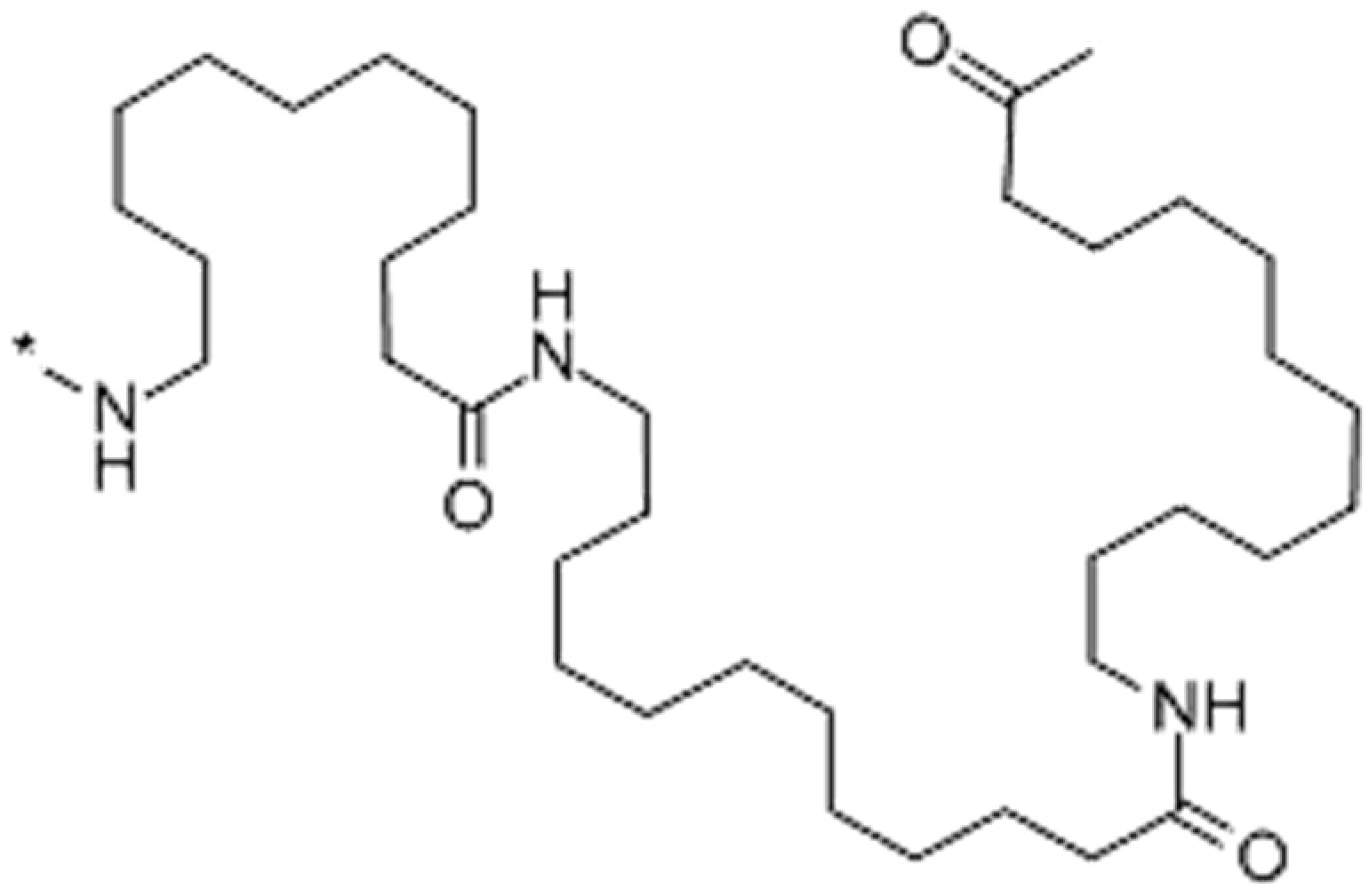
The Vestamid NRG range consists of a series of polyamide 12 polymers, whose chemical structure is shown in
Figure 1, engineered for high impact strength and chemical resistance. They are of a high viscosity and plasticised, and are designed specifically for extrusion. Vestamid NRG 1001 and Vestamid NRG 6001 were selected for processing as they are easily processable and met the previously mentioned selection criteria: they both have high Young’s modulus with the 1001 being 380 MPa and the 6001 390 MPa, processable at 220–250 °C and a low water absorption as a result of having a relatively small concentration of amide groups within the polymer chain [
17].
Vestamid NRG 1001 and NRG 6001 both have densities of 1.02 g/cm3 and both have melt temperatures of 172 °C. For the aforementioned reasons, the Vestamid NRG polymers were selected for use in this study.
2. Methods
The ASTM E1131-08 (2014) “Standard Test Method for Compositional Analysis by Thermogravimetry” was followed for the thermogravimetric analysis (TGA). A Simultaneous Thermal Analyser TGA Q600 from TA Instruments (New Castle, DE, USA) was selected for this.
The TGA was set to perform the testing under air commencing at room temperature (around 20 °C) at a ramp rate of 5 °C per minute up to 800 °C is achieved in order to determine the degradation temperatures of the polymers prior to extrusion. An empty crucible was placed in the TGA, the furnace closed and the machine allowed to tare. The crucible was then three quarters filled with one of the polymers, around 15 mg of polymer, and placed back in the TGA. The test was then initiated using the bundled software from TA.
A Eurotech single screw extruder (Eur.ex.ma, Tradate, Italy) with fibre spinning set-up was employed throughout the extrusion processing. The set-up consisted of an 80 filament die, each hole 1 mm in diameter, combined with two large diameter machine driven wheels which were heated, and 3 metal guide wheels to assist transfer of the fibres from wheel to wheel to collection spool. These powered wheels allowed for continuous drawing of the fibres.
The polymers were placed in an oven at 110 °C for 2 h in order to expel any moisture from them prior to the extrusion. This was a precautionary step in an attempt to reduce the amount of imperfections during the extrusion process caused by the presence of moisture within the barrel [
16]. As the polymers were drying the extruder was purged with polypropylene in order to remove any remaining polymer residue. Once this purging process was completed the hopper was loaded with the particular Vestamid NRG polymers.
The extrusions were processed at below 225 °C in order to avoid material degradation. To reduce the risk of thermal degradation the temperature was ramped up through each zone as per
Table 1.
Due to the extremely low diameters of the extruded fibres, the blower unit had to be turned off as it resulted in fibre distortion. This allowed for the hot fibres to be drawn out by a powered wheel. Varying the rpm levels up to 23 rpm resulted in a variety of diameter samples. The parameters used in the extrusion of NRG 1001 were as follows: Back pressure 29 bar, material pump rotation rate of 4 rpm and haul-off rate of 23 rpm.
The limit of the haul-off rate was 23 rpm, not because of machine restrictions but due to it being the maximum speed the material could be manually collected onto a spool. As Vestamid NRG 6001 contains more plasticiser it was able to be drawn out/extended further. However, due to the draw rate being at a maximum for collection, the material pump rate was instead reduced. This meant that less material was being ejected from the extruder instantaneously giving a lower diameter fibre. The draw rate remained the same, meaning, that the already lower diameter material was able to have its diameter reduced again. All 80 filaments were collected onto a single spool.
A similar process was employed to produce the monofilament fibres, using the same parameters, but using a single hole from the die.
As the Instron 3344 tensile testing machine requires the insertion of fibre tex for its calculations the fibre fineness was calculated. 10 m sections of each fibre were cut and weighed using an analytical balance and a value of weight in grams recorded to an accuracy of 0.1 mg. These values were then multiplied by 100 in order to give the fibre tex value. 10 m was selected in order to give a fair representation of the potential variation across the yarns whilst avoiding the waste engendered by a greater quantity.
An Instron 3344 tensile testing machine (Instron, Darmstadt, Germany), equipped with a 500 N load cell and Series 2710-200 Screw Action Grips, was utilised throughout the fibre tensile testing. The tensile testing was done in accordance with American Society for Testing and Materials ASTM D3039/D3039M-1507 “Standard Test Method for Tensile Properties of Single Textile Fibres”. Card tabs were bonded to either end of the filaments in order to prevent fibre damage occurring from the grips as this damage could cause breakage to occur at the root of the grip invalidating the test. A gauge length of 1 inch (25.4 mm) was used and a crosshead speed of 20 mm/min. Usually stress is calculated by dividing the load by the material’s cross-sectional area. However, in an attempt to negate any potential diameter variations between the fibres, stress was calculated by dividing force (in cN) by weight of the fibre (in tex) as per ASTM D3039/D3039M-15. This provides a comparable set of results, regardless of diameter variation or of number of filaments. Due to the twist in multifilament yarns the cross-sectional area can vary making this approach even more desirable [
18].
To measure the tex, 10 m sections of each of the yarns were cut and weighed using an analytical balance and a value of weight in grams was recorded. Therefore, the recorded results were multiplied by 100 as the tex is mass (in grams) of the yarn per 1000 m of that yarn [
15]. 10 m was selected in order to give a fair representation of the potential variation across the yarns whilst avoiding the waste of any greater a quantity.
The larger diameter fibres were tested as single monofilament fibres. The lower diameter multifilament fibres had a twist introduced at 20 twists per metre as per Chudoba et al.’s experimental work which showed that for optimum tensile strength of a multifilament fibre of AR-glass yarn, 20 twists per meter was required [
19].
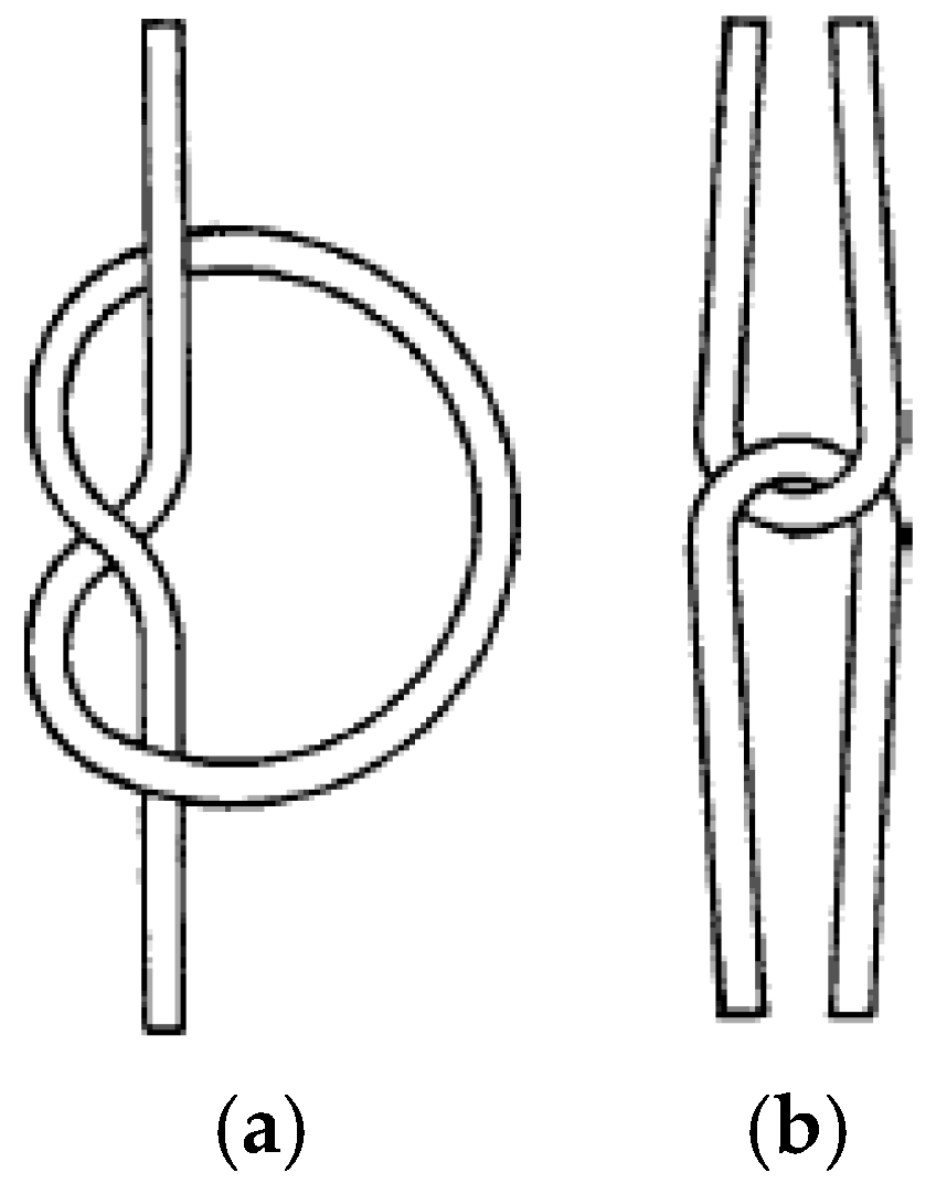
As the fibres were designed to be stitching fibres, they were put under both knotting and looping forces during the stitching process. ASTM D3217-07 “Breaking Tenacity of Manufactured Textile Fibres in Loop or Knot Configurations” covers a tensile test method which mimics these forces. This standard obeys the principles of ASTM D3039/D3039M-15, with a few minor exceptions: The fibre is tied in a single overhand knot, as shown in
Figure 2.
It is important that the knot is introduced in the middle of the test specimen. The gauge length between the grips in this case was set to 1 inch (25.4 mm). The same setup applies to the loop samples but here the knot becomes a loop made from two strands of material. The gauge length remained constant at 25.4 mm. The loop itself consists of two separate filaments, interlocked through each other in a “U” shape, as shown above.
A minimum of 5 tests for each material under each tensile test set-up was chosen. If during any testing the fibre began to become detached from the resin tabs the result was discarded. The same approach was taken with samples which may have kinked or been damaged during the tab bonding stages.
In this study, a JEOL JSM-IT100 InTouchScope SEM™ (JEOL, Welwyn Garden City, UK) was used for all the scanning electron microscopy (SEM) imaging. The fibre samples were prepared by being cut into sections of 2 cm in length. These were then placed into an Emitech K500x sputter coater. The vacuum was set at 8 × 10⁻² millibars (mbar) of pressure for 2 min and 30 s at 3 milliamps (mA) in order to sputter 0.2 nanometres (nm) onto the samples. Purshuield Argon gas UN1006 was used in the chamber. The fibres were then turned over and the process repeated in order to ensure that they were fully gold coated.
The gold-coated fibre samples were then mounted onto stubs and placed into the SEM. 10 kV at a magnification of ×45 was employed giving a clear image of the surface topography of the fibres while still allowing enough of a field of view to perform diameter analysis on the fibres. The measure function within the SEM was exercised 5 times on each fibre sample measuring the diameter at 500 µm intervals at the selected ×45 zoom. Any abnormalities within the samples were also examined under the SEM. 10 fibre samples from each fibre produced were analysed providing 50 diameter measurements for each fibre type in order to provide a fair representation of each fibre.
The diameter measurements recorded on the SEM were then input into Microsoft Excel in order to provide a medium to analyse this data. Quantum XL2016 add-on for Excel was also employed for further statistical analysis of the data.
Process capability index (Cpk) is a metric to indicate how near an operation or process is running to required predefined specification or tolerance limits while still taking into account natural process variation. A larger Cpk increases the probability that the results will fall within the specifications [
21].
Cpk is calculated using a number of components:
Process capability (Cp)—the ratio of specification range to the standard deviation of the process
Process capability at upper level (CpU)—the difference between the upper specification limit and the centre of the standard deviation
Process capability at lower level (CpL)—the difference between the lower specification limit and the centre of the standard deviation. Thus,
Equation (1) Process capability index calculations [
22].
The upper (USL) and lower specifications limits (LSL) for the Cpk analysis were taken at ±25 microns of the average fibre diameter for each fibre, being around a 10% variation in the lowest expected fibre diameters from previous testing.
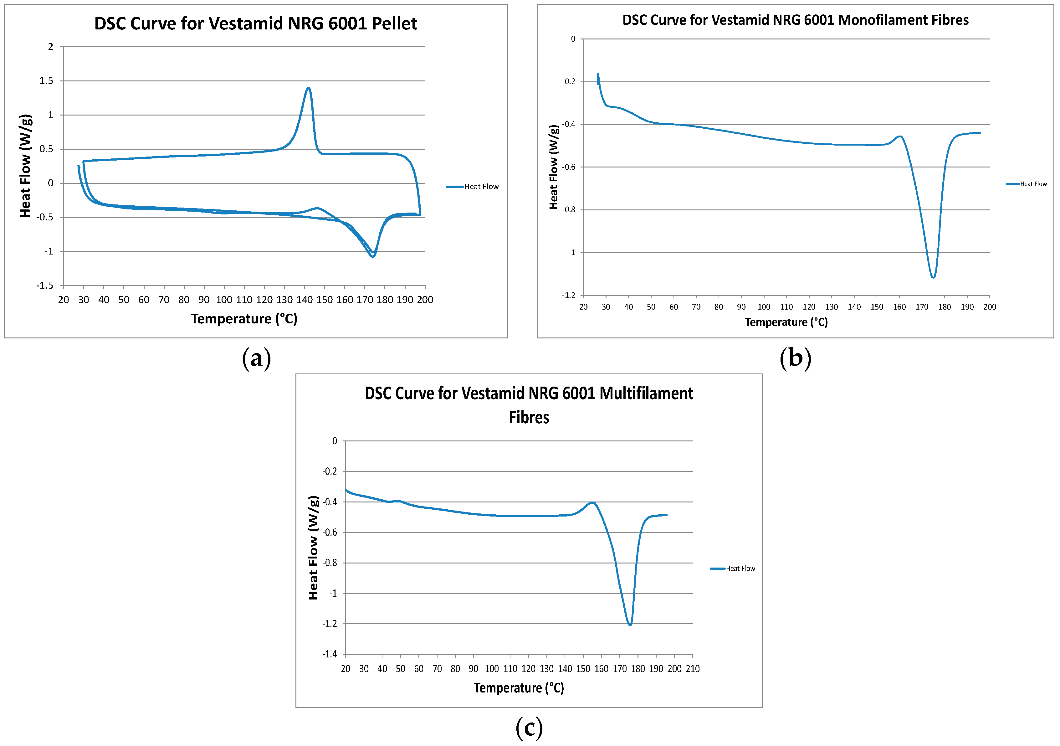
Differential scanning calorimetry as used to measure crystallinity, glass transition and melt temperature of the polymers and polymer yarns. 10 milligrams (mg) of polymer was weighed using a Satorius M-Power analytical balance and then placed into a hermetic pan. A lid was placed onto the pan and sealed using a press. The sample was placed in the TA Q100 MDSC machine (TA Instruments, New Castle, DE, USA) alongside a reference pan, which in this case contained only air. The test was set up to run under nitrogen gas at a temperature range of room temperature (around 20 °C) to 200 °C at a rate of 10 °C per minute. This test was performed with the polymer pellets, the extruded monofilament polymer and the extruded multifilament polymer with carbon fibre. The enthalpy of pure PA12 was taken as 245 (J/g) [
23].
3. Results
3.1. Thermogravimetric Analysis
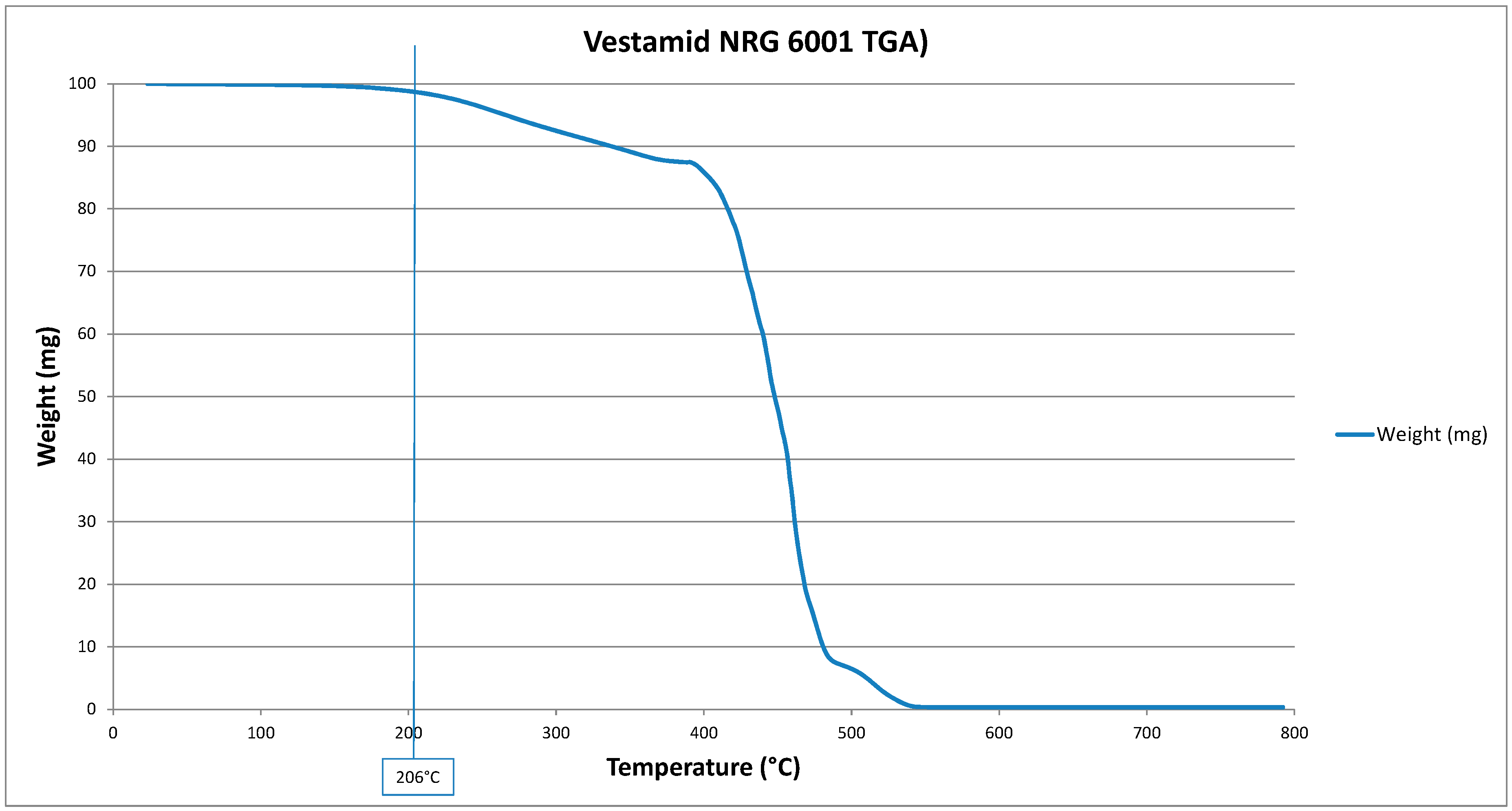
As is shown in
Figure 3, at 206 °C Vestamid NRG 600l begins to undergo degradation. This provides a decent 34 °C range between melt and thermal degradation at which this polymer can safely be extruded with minimal risk of degradation.
At 205 °C the Vestamid NRG 1001 begins to suffer from thermal degradation. The manufacturer recommends extrusion temperatures between 220 °C and 250 °C. The TGA results revealed that at 250 °C the material will have incurred a weight loss of almost 4%, implying thermal degradation.
3.2. Fibre Fineness
Following the drawing of the fibres, the NRG 6001 fibres were of a lower diameter than the NRG 1001 fibres. However, the 6001 still possess a higher tex value than the NRG 1001. This can be seen in
Table 2 below.
The recorded weights for the multifilament fibres are for the average weight of 1 of the 80 filaments.
3.3. Differential Scanning Calorimetry
As both of the Vestamid polymers begin suffering from thermal degradation slightly upwards of 200 °C the DSC was run at 10 °C per minute from room temperature, at around 25 °C, until 200 °C. The literature states that the enthalpy of pure PA12 is 245 (J/g) [
23].
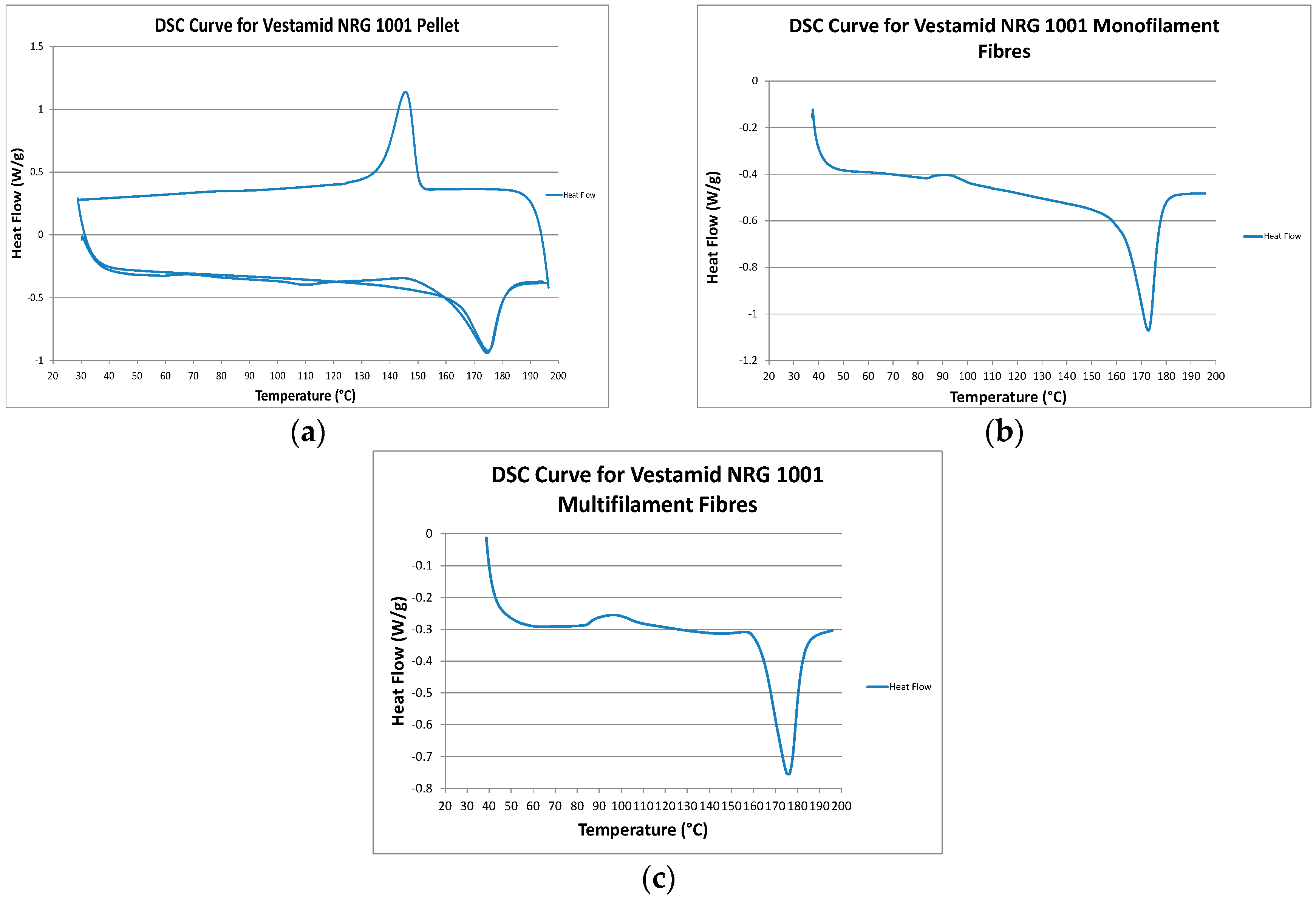
The DSC curves are displayed in graphical form in
Figure 4 and
Figure 5 and the results in tabular form in
Table 3.
However, the changes to glass transition temperature (T
g) observed following extrusion monofilament material in
Table 3 correlates to their change in crystallinity with a decrease in T
g being seen alongside a decrease in crystallinity. The 6001 was expected to have a lower T
g due to the increased amounts of plasticiser weakening the intermolecular forces that exist between the polymer chains.
The crystallinity of the multifilament fibres was increased slightly which is likely to be due to strain induced crystallization due to higher molecular alignment in the smaller diameter fibres. This increase in crystallinity would also attribute to the multifilament fibres possessing a greater tensile strength than their monofilament equivalent as increasing the crystallinity leads to an improvement of secondary bonding due to molecular chains being parallel and closely packed [
24].
The higher crystallinity values for 6001 relative to the 1001 grade may be due to a greater crystallization rate in the presence of plasticizer (more molecular mobility). As the 6001 also has a lower diameter in both mono and multifilament forms this would result in quicker cooling and freezing in of a higher level of molecular orientation.
3.4. Scanning Electron Microscopy
The fibre surface, in
Figure 6, has formed in a wave like melt pattern, due to the method by which the yarns were produced. However, they do remain at a relatively consistent diameter despite this pattern.
Although all of the individual fibres have a smooth surface, as in
Figure 6, they combine to form a material of varying diameter. This could potentially impair the passage of the fibres though the woven composite. Within medical sutures this issue exists with multifilament sutures impairing the passage through, and potentially damaging, the surrounding tissue [
25]. A monofilament fibre with a consistent diameter and smooth surface would not suffer the same issues.
A small amount of deviation was to be expected from the fibres which were extruded nearest the screw hole which holds on the heater band for the die as this hole absorbs the heat from the nearest die holes. This can lead to a build-up of material cooled enough to partially block those die holes. However, the other 77 or so die holes should not suffer with the same issue giving rise to the expectation of consistent diameter filaments.
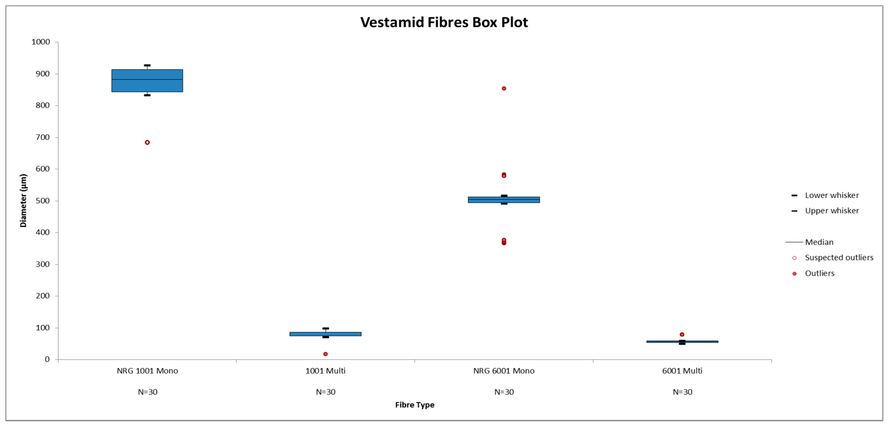
The diameter variation of the fibres are shown in
Figure 7 in the form of a box plot. It is apparent from the box plot that the monofilament fibres have a larger standard deviation than their multifilament counterparts. This is also evident from the figures in
Table 4.
As per previous work on through-thickness stitched composites showing that the lower the diameter of the yarn the less deterioration of the in-plane laminate strength, the yarns were drawn out as much as possible [
11,
25]. As the NRG 6001 contains a greater amount of plasticiser it could be drawn out further into lower diameter filaments. This accounts for the 22.9 μm average diameter difference between the NRG 1001 and the NRG 6001. The NRG 1001 draw ratio was calculated at 113.2 whereas the NRG 6001 draw ratio was 72.2. A higher draw rate should result in an increase in the fibre’s structural orientation potentially producing higher oriented polymer chains which should give an increase in crystallinity and melt temperature [
26].
This was demonstrated in
Table 3: Differential Scanning Calorimetry Analysis for Vestamid Polymer in which the material with the highest draw ratio, NRG 1001, had the larger percentage increase in crystallinity. This could be due to differences in cooling rate.
As mentioned, a small amount of deviation was to be expected from the fibres which were extruded nearest the screw hole. However, the other 77 die holes should not suffer with the same issue, giving rise to the expectation of consistent diameter filaments.
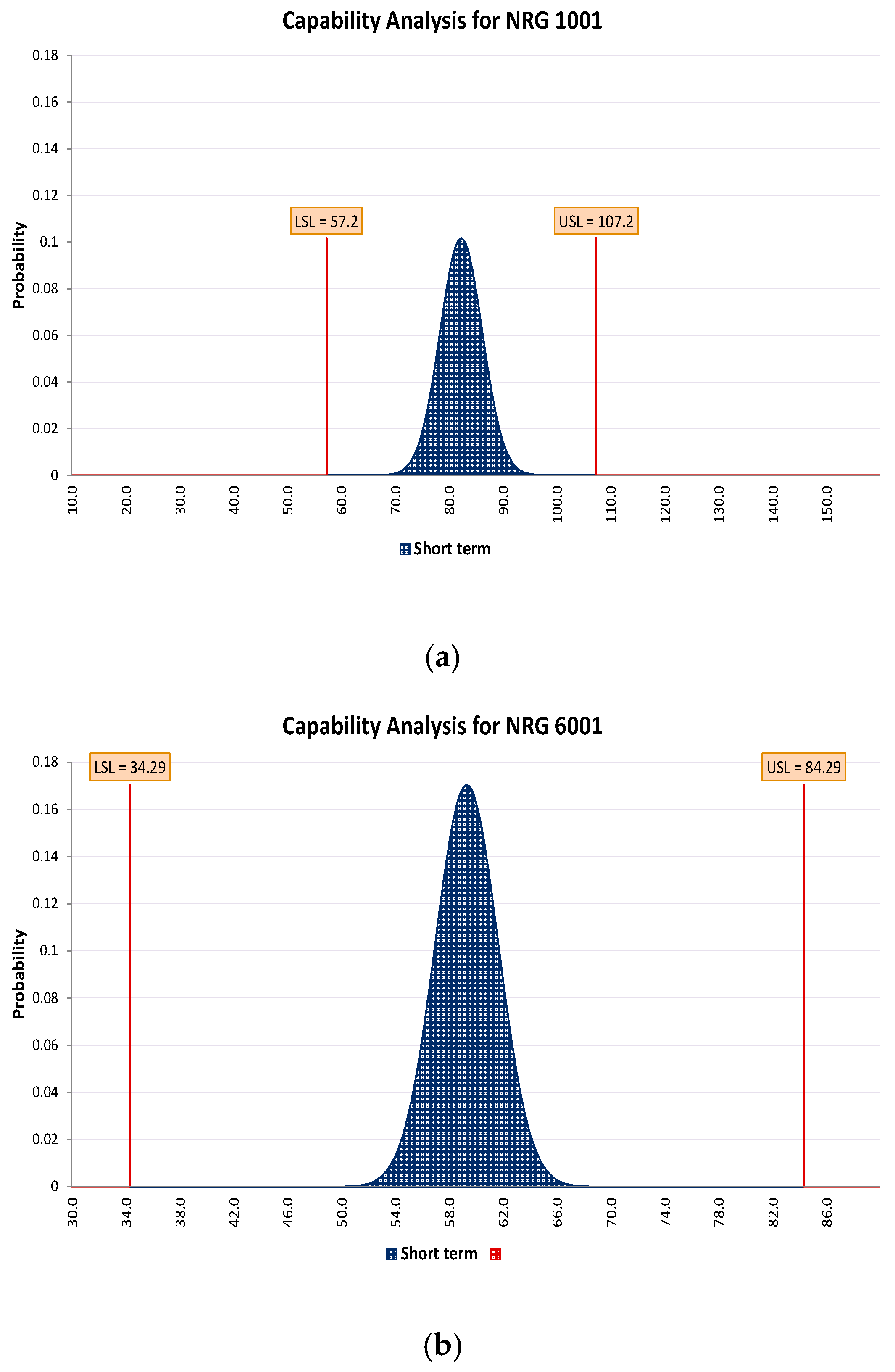
Using Equation (1) and the diameter measurements recorded on the SEM, a Cpk value of 2.121 was calculated for the NRG 1001, producing a distribution as shown in
Figure 8. This suggests that the extrusion process is capable of producing consistent diameter filaments of NRG 1001. A very capable 3.5565 Cpk value was calculated for diameter consistency of the NRG 6001 single fibres, indicating an increased level of diameter consistency.
Figure 8 shows that the diameter measurements recorded remained within the ±25 micron upper and lower limits. Both of the graphs contain a relatively narrow distribution with the NRG 6001 having a both less of a distribution spread and higher probability of achieving a diameter within this range.
3.5. Tensile Testing
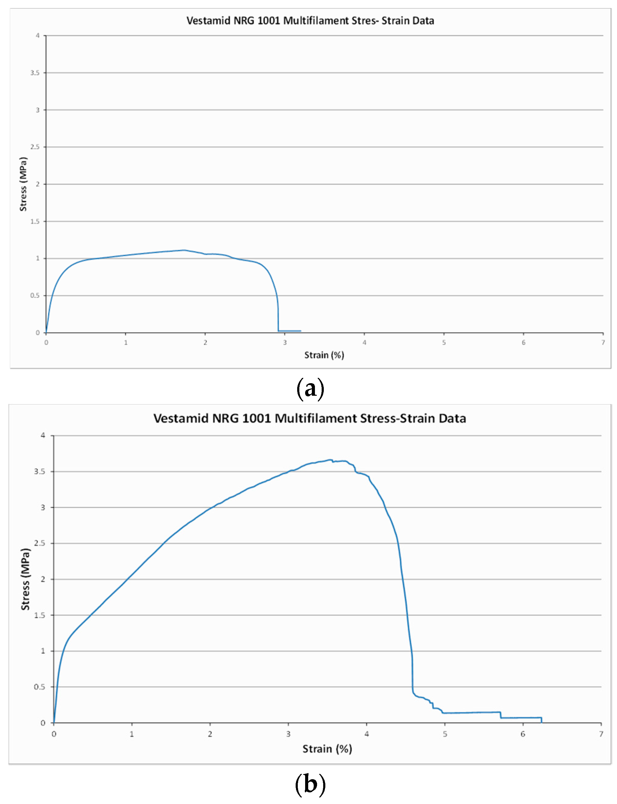
The plasticity of the two polymers and their ability to be drawn into a very fine material prior to fracture resulted in a significant extension prior to fracture. This was more prevalent with the monofilament fibres as they had not been drawn prior to testing, unlike the multifilament fibres.
Figure 9 displays the stress-strain curves for NRG 1001 mono and multifilament fibres. The extension prior to failure shows that these polymers are not brittle materials, but visco-elastic.
As stitching provides an improvement in delamination resistance by retention of the laminate layers during a crack opening under tensile loading, the stitches’ mechanical properties will directly influence their ability to withstand delamination [
11].
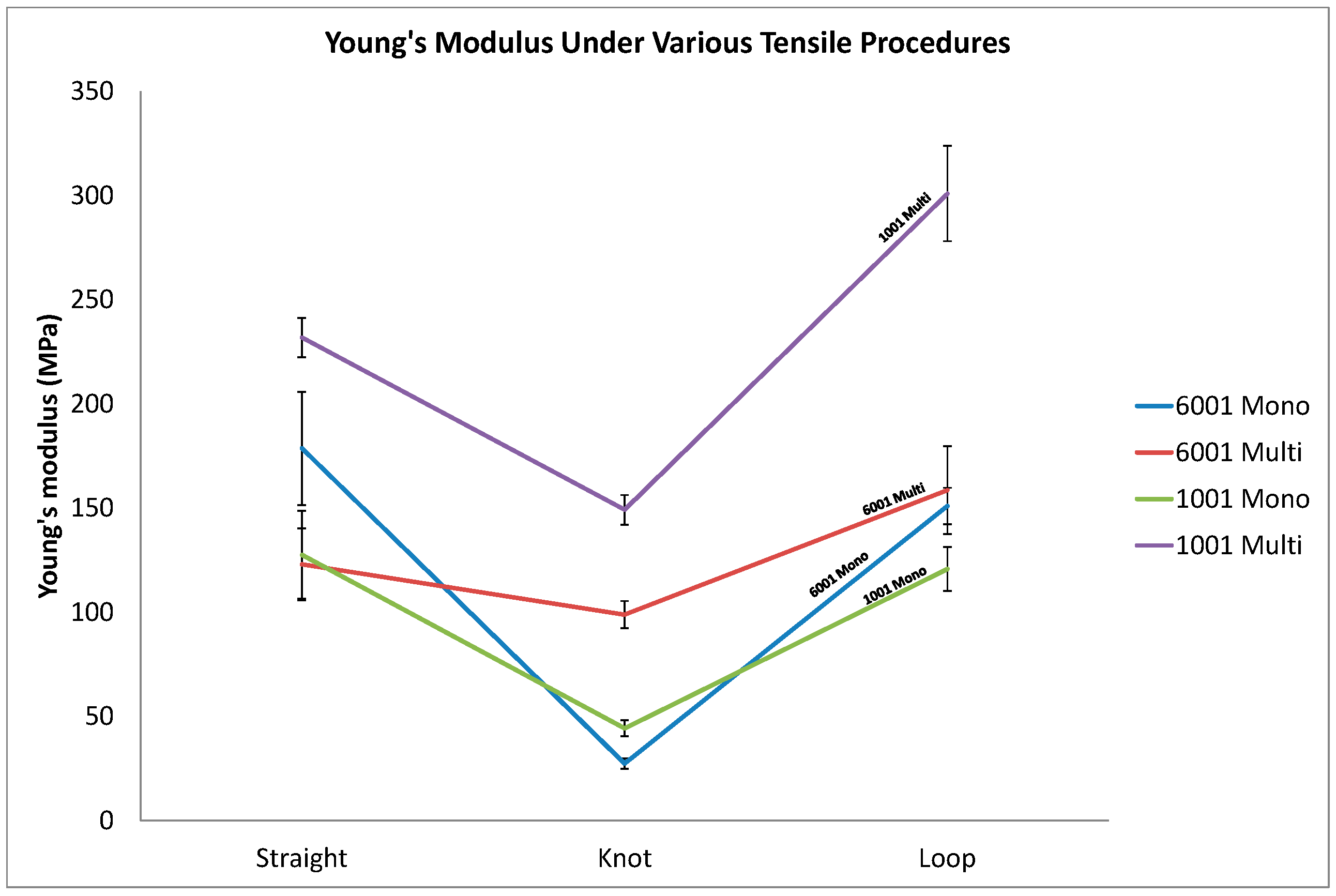
All of the yarns experienced a decrease in their Young’s modulus when looped and a significant decrease in Young’s modulus when knotted. The 6001 monofilament fibres displayed a 37% increase in Young’s modulus compared to their equivalent monofilament counterparts in the straight configuration. However, once knotted or looped the monofilament fibres suffer a much greater decrease in Young’s Modulus. Illustrated in
Figure 10 the 6001 monofilament fibres suffer a 57.6% decrease when knotted compared with the 6001 multifilament fibres which still experience a significant 21.7% decrease. As the 6001 fibres have a greater amount of plasticiser they have a lower modulus in their multifilament form.
This data is further summarised in
Table 5 below. In almost every instance the multifilament fibres have an increased stiffness when compared with the monofilament equivalent. This could be as a result of their increased crystallinity as a result of the drawing process causing increased strength and stiffness by improved molecular orientation as is described by Mahyudin et al. [
24].
Although the Young’s modulus must not be too large to prevent flexure during the stitching process, a degree of stiffness is required. An increase in Young’s modulus may allow the yarns to act as an alternative load path within the composite, causing any potential delamination cracks to be directed through the composite, from stitch to stitch, thus reducing the effect of the cracking force on the laminate [
11].
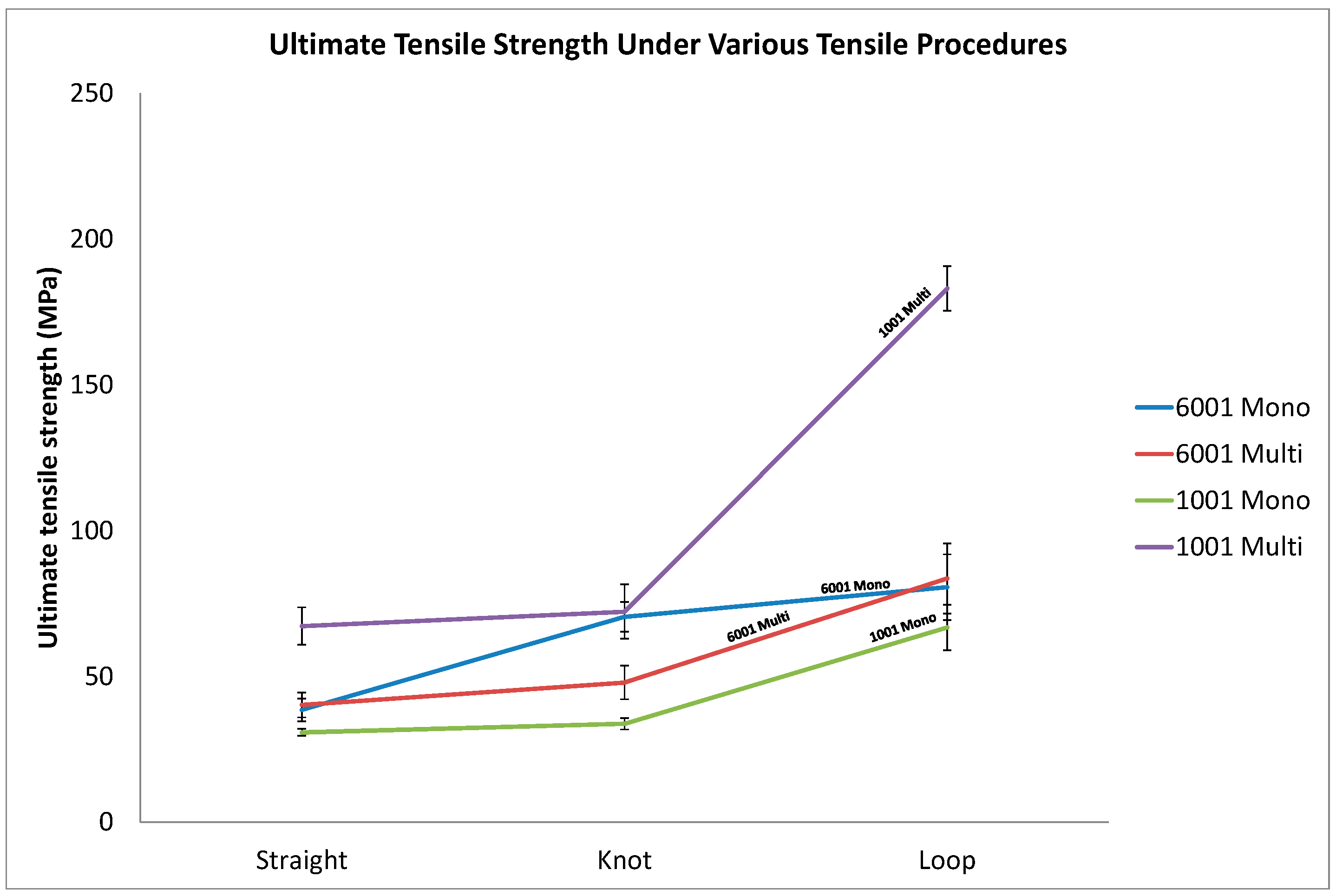
In their straight fibre tensile tests, the 1001 fibres gave a 74.3% increase in ultimate tensile strength, when in their multifilament state. The 6001 gave a ultimate tensile strength increase of just 4.3% when compared with its monofilament equivalent. The larger surface area of the multifilament fibres when spread out in the loop configuration could have attributed to their increase in ultimate tensile strength evident from the graph shown in
Figure 11.
It can be seen that in the majority of instances, with the exception of the knotted 6001 fibres, that the ultimate tensile strength of the lower diameter filaments exceeds that of the monofilament fibres. This could potentially be attributed to the fact that the multifilament yarns had a higher percentage crystallinity than their monofilament counterparts, thus giving the improvement in ultimate tensile strength [
24]. This can be seen in tabular form below in
Table 6.
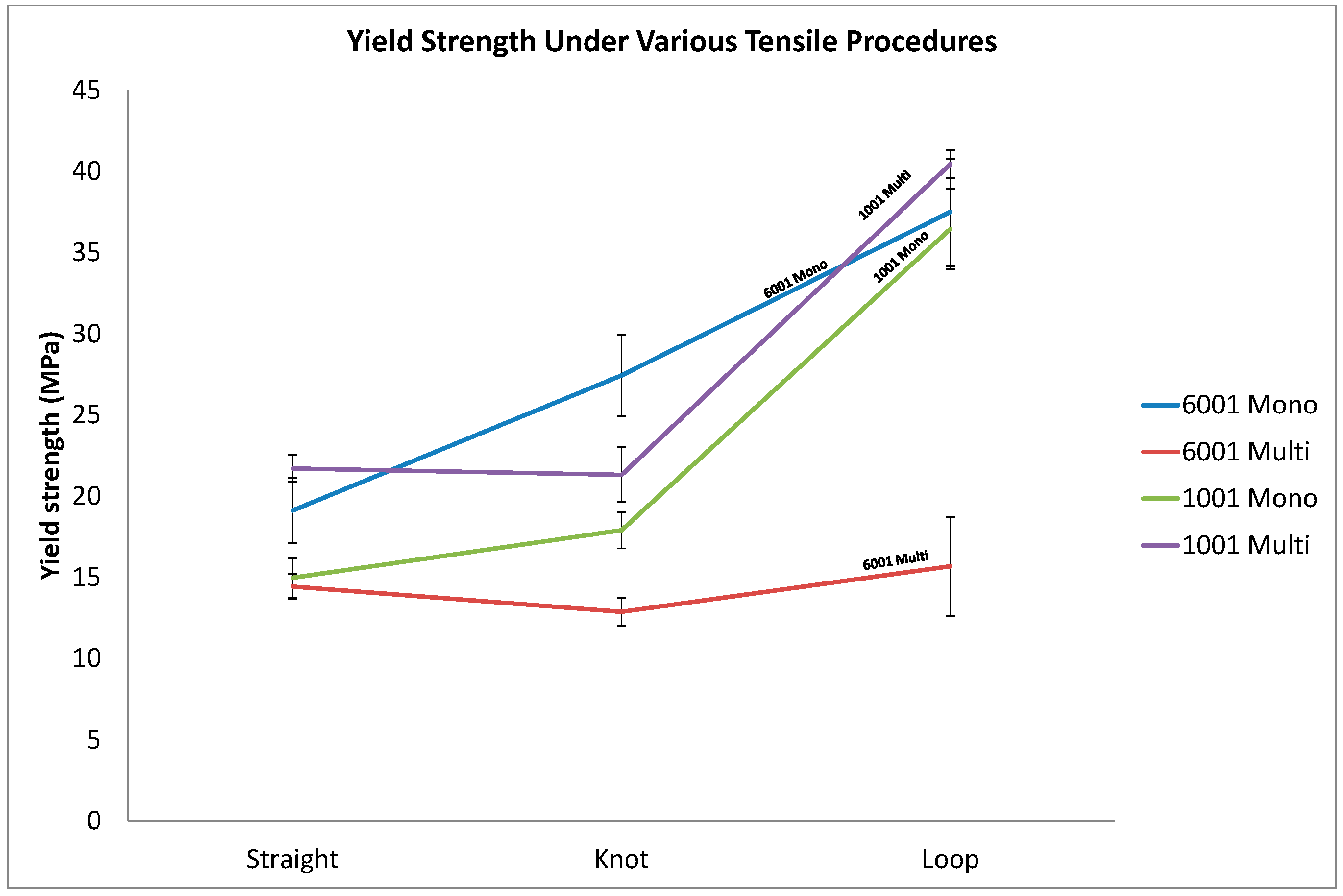
Despite the 6001 multifilament fibres generally having a higher ultimate tensile strength than their monofilament equivalent,
Figure 12 shows that in almost all cases the multifilament fibres began to yield earlier than the monofilament. The bulk of the monofilament yarn did not yield entirely, instead only a few filaments yielded. This was the cause of the large variation in results denoted by the error bars for the multifilament fibres in
Figure 12. This could be partially attributed to the 6001 multifilament fibres being drawn significantly more than any of the other fibres thus reducing the opportunity for as much extension and fibre alignment prior to yield.
The 1001 fibres responded as expected: in all of the configurations the multifilament 1001 fibres yielded at a higher force than the 1001 monofilament fibres. This is also evident from
Table 7:
Tensile analysis revealed that multifilament fibres offer significant improvement in ultimate tensile strength over their monofilament equivalent, particularly when knotted or looped. Multiple fibres of lower diameter exhibited a higher breaking strength than a single monofilament fibre of a diameter similar to that of the multifilament fibres combined.
The 6001 multifilament and some of the 1001 multifilament fibres begin to yield prior to the monofilament yarns even though the bulk monofilament yarn did not yield entirely. This would suggest that multifilament fibres are more suitable for structural retention of the laminate regions.
This would seem to agree with Griffith’s “Theory of Brittle Fracture” in which Griffith demonstrated that the diameter of a fibre is inversely proportional to its breaking stress, or ultimate tensile strength. Griffith suggested that this was as a result of the fact that a single line of molecules in the form of a fibre must possess the theoretical strength of those molecules, whereas in larger diameter materials microscopic flaws reside within the bulk material resulting in stress concentration in those areas and ultimately reducing the breaking stress of the material [
27]. This would correspond to the fact that the multifilament yarns exhibited a greater ultimate tensile strength than their monofilament counterparts. However, the drawing process increased the percentage crystallinity of the multifilament fibres, which would also be a factor in the mechanical property increase in the lower diameter filaments. Being that the majority of the multifilament fibres also yielded above their equivalent monofilament fibres further points towards a combination of crystallinity increase and Griffith’s theory. To determine which of these is the dominating factor would require further testing. It is likely that molecular alignment and crystallinity increase of the lower diameter fibres lead to Griffith’s theory being relevant, but not the undermining factor [
28].
Given the large variation in percentage elongation prior to break shown in
Figure 13 it is difficult to draw firm conclusions. When knotted the monofilament yarns extended further than when in their straight configuration. The tightening of the knot would attribute greatly to this extension recording. The multifilament yarns would not experience such a knot tightening as due to their lower diameter they have a greater bend radius, allowing a tighter knot to be produced for testing.
In the knotted configuration, the monofilament yarns extended further than their multifilament equivalents with the 6001 having a 60.6% greater extension than the multifilament. It is expected that during the stitching process the yarns will be extended slightly as part of their insertion. However, all of the yarns extended over 300% prior to fracture in both configurations suggesting that they are more than capable of surviving the expected elongation during the stitching process.
4. Conclusions
Monofilament and multifilament thermoplastic yarns were produced from Vestamid NRG 1001 and Vestamid NRG 6001, engineered polyamide 12, by means of extrusions and drawing. Despite an extensive literature review, no other instances of these polymers being used to create a yarn for stitching applications were found. Following Cpk analysis it was found that these polymers could be made into consistent yarns.
Tensile analysis revealed that for the 1001 grade material the multifilament fibres offer significant improvement in ultimate tensile strength over their monofilament equivalent, particularly when looped. Multiple fibres of lower diameter exhibited a higher breaking strength than a single monofilament fibre with a diameter similar to that of the multifilament fibres combined. The observed improvements with the multifilament 6001 grade of material were not as significant, and in one instance even caused a reduction in ultimate tensile strength. This could be potentially attributed to the 6001 grade being drawn out into a lower diameter. However, some of the multifilament fibres begin to yield prior to the monofilament yarns, even though the bulk monofilament yarn did not yield entirely. This would suggest that multifilament fibres are more suitable for structural retention of the laminate regions. However, increasing the crystallinity of the monofilament yarns would potentially improve their mechanical properties, but not anywhere near that of an equivalent sized multifilament yarn.
All of the yarns extended over 300% prior to fracture in both configurations suggesting that they are more than capable of surviving the expected elongation during the stitching process.
Purely based upon a material property aspect, multifilament yarns appear to be better suited to stitching yarns than their monofilament counterpart. However, they may pose an increase in difficulty when it comes to stitching. Further work will determine whether the multifilament yarns will produce any difference in situ.
