Abstract
For the development of high efficiency porous supports for composite membrane preparation, polysulfone (PSf) hollow fiber membranes (outer diameter 1.57 mm, inner diameter 1.12 mm) were modified by air plasma using the low temperature plasma treatment pilot plant which is easily scalable to industrial level and the Piranha etch (H2O2 + H2SO4). Chemical and plasma modification affected only surface layers and did not cause PSf chemical structure change. The modifications led to surface roughness decrease, which is of great importance for further thin film composite (TFC) membranes fabrication by dense selective layer coating, and also reduced water and ethylene glycol contact angle values for modified hollow fibers surface. Furthermore, the membranes surface energy increased two-fold. The Piranha mixture chemical modification did not change the membranes average pore size and gas permeance values, while air plasma treatment increased pore size 1.5-fold and also 2 order enhanced membranes surface porosity. Since membranes surface porosity increased due to air plasma treatment the modified membranes were used as efficient supports for preparation of high permeance TFC membranes by using poly[1-(trimethylsilyl)-1-propyne] as an example for selective layer fabrication.
1. Introduction
Multilayer composite membranes for the membrane separation technologies on molecular level, e.g., gas separation, pervaporation, reverse osmosis, and organic solvent nanofiltration are increasingly attractive due to their advantages over integrally skinned asymmetric (Loeb-Sourirajan) membranes. The development of thin-film composite (TFC) hollow fiber membranes is one of the major breakthroughs of membrane technology for large-scale industrial applications because of two main reasons: (i) composite membranes contain less than 1 g of the custom-made, high cost selective polymers per square meter of the membrane; and (ii) hollow fiber modules provide the high membrane area to module volume ratio (1000–10,000 m2/m3) which results in high productivity per volume unit and cost-efficient production.
To deposit thin-film defect-free selective layer, a high efficiency porous support for TFC membrane preparation is needed. Polysulfone (PSf) is an important material in the field of polymeric porous membranes because of its mechanical, thermal and chemical stability as well as its excellent film forming properties [1].
The porous structure of PSf membrane, as well as the properties of the surface (surface free energy, the presence of functional groups, micro-roughness) can significantly affect the transport properties of composite membranes produced.
Modified PSf membranes can be obtained in different ways [2]. One applicable option is adding modifying macromolecules [3] or carbon nanotubes [4], in the polymer dope solution as an additive. By using interfacial polymerization method, polymers could be coated onto PSf membranes [5,6], and the polymerization occurs at the membrane surface and pore surface. In addition, porous PSf hollow fiber supports can be used to growth thin layers of microporous materials (e.g., MOFs— metal-organic frameworks, see [7]) for gas separation application.
Hydrophilization of the porous hydrophobic support is one of the factors providing a successful coating of the membrane [8]. Low-temperature plasma treatment with non-polymer-forming gases has been used in recent years as a useful tool to modify the surface properties of different materials, including PSf porous membranes [9,10,11,12,13,14,15,16,17,18,19]. Plasma allows to improve adhesion or wettability, as it generates the active species, capable of activating the upper surface molecular layers without involving the polymer bulk.
Three basic phenomena affecting porous membrane properties can take place in plasma using non-polymer-forming gases [9]: reactions yielding in volatile products as well as etching lead to an increase in pore diameter and porosity; modification of the chemical structure of the surface layer, giving hydrophilization or hydrophobization, depending on plasma conditions; deposition of polymer film made of volatile products may lead to declined porosity.
Piranha is a mixture of H2SO4:H2O2 (3:1), is highly oxidative and is used to clean photoresist and other hard to remove organic residue from silicon wafers. Organics are destroyed and eliminated by wet-chemical oxidation, but inorganic contaminations, such as metals, are not desorbed.
In this study, the air plasma and piranha etching of porous asymmetric PSf hollow fiber membrane are investigated using scanning electron microscopy (SEM), confocal scanning laser microscopy (CSLM), IR spectroscopy, contact angle and gas permeance measurements. The thin film composite membranes using poly[1-(trimethylsilyl)-1-propyne] (PTMSP) as a non-porous selective layer and air plasma etched PSf porous hollow fiber membranes as a support were prepared and selective layer integrity was confirmed by gas permeation testing. The membrane selectivity can be improved by coating PTMSP on porous supports, even if this polymer is not greatly selective and many attempts have been reported to increase this [10,11].
2. Materials and Methods
2.1. Materials
The materials used to prepare spinning solutions were PSf pellets, Ultrason® S 6010 (from BASF) and N-methylpyrrolidone (NMP 99% extra pure) supplied from Acros Organics (Geel, Belgium), used as the base polymer and solvent, respectively, with no supplementary purification. The pore-forming additive used in the polymer solution was polyethylene glycol having average molecular weight 400 g/mole (PEG-400) supplied from Acros Organics. For membrane modification 37% aqueous hydrogen peroxide solution and chemical pure concentrated sulfuric acid from Chimmed (Moscow, Russia) were used.
2.2. Spinning Solutions Preparation
For spinning solutions preparation mass ratio PSf to PEG-400 was 1:1.25. PSf concentration was 23.9 wt. %. PSf and PEG-400 were placed into temperature-controlled reservoir and stirred under 70 °C temperature and mixing rate 150 rpm; after that, NMP solvent was added into the solution and stirring continued under 120 °C and 500 rpm for 4–5 h. After preparation, spinning solution was cooled to 23 ± 0.1 °C and its dynamic viscosity was measured using Brookfield viscometer DV2T-RV and RV-07 spindle (Brookfield AMETEK, Middleboro, MA, USA) (rotation speed 100 rpm). For spinning solution with composition described above average dynamic viscosity value was 32,000 ± 400 cPs.
Hollow fiber membranes spinning was preceded with dope solution heating to 120 °C (in order to reduce its viscosity) and filtration through metal mesh (cutoff rating 4–5 μm) under gas pressure 0.18–0.20 MPa. After filtration, the polymer solution was cooled to room temperature and degassed under vacuum. Filtration and degassing steps are extremely important for hollow fiber spinning because nonsoluble particles or gas bubbles present in the spinning dope solution leads to fiber breakage.
2.3. Fabrication of Porous Hollow Fiber Membranes
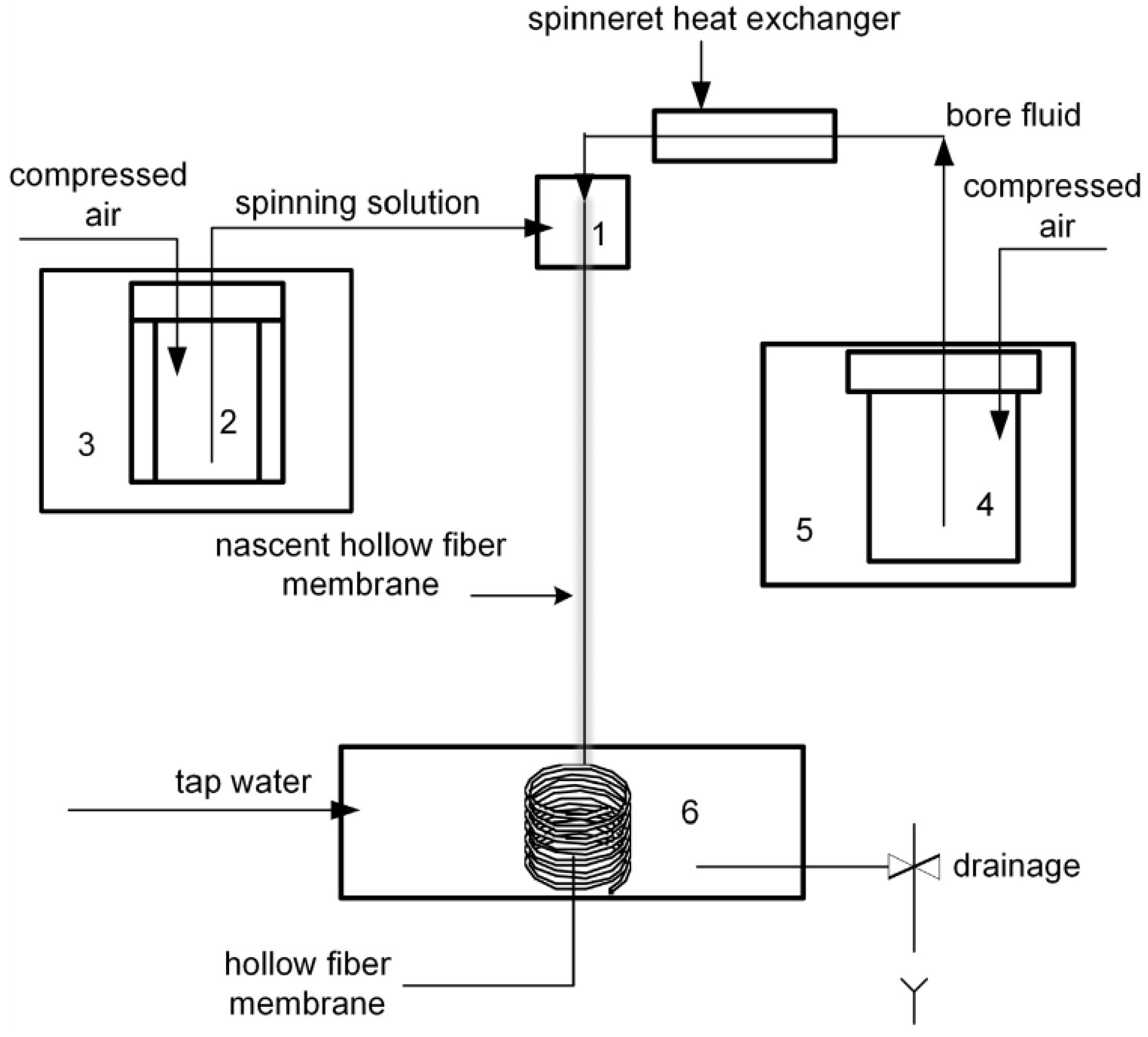
Porous hollow fiber membranes were prepared via a dry-wet phase inversion technique in the free spinning mode in air when bore fluid was brought into liquid polymer solution orifice. Under this mode, the spun fiber gets into coagulation bath by gravity and coils of its own accord. No external coagulation bath was used in the process allowing instrumental design facilitation. The spinneret having ring sectional area 1.77 mm2 was used. Scheme of the setup used for the fabrication of hollow fiber membranes was similar to that used in [12] and is shown at Figure 1.
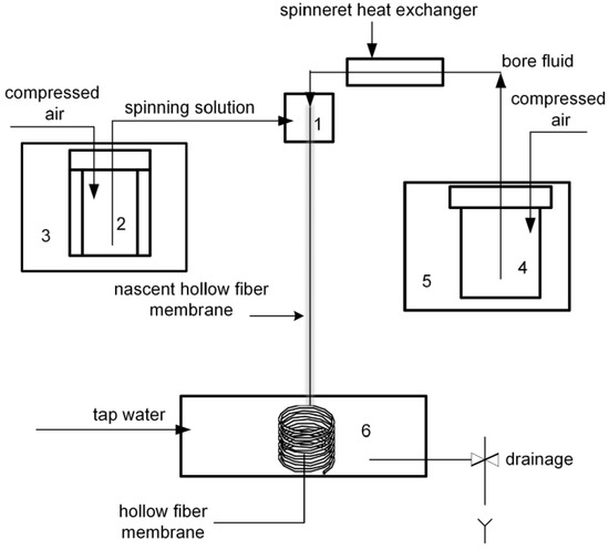
Figure 1.
Functional diagram of the setup used for spinning of hollow fiber membranes. 1—spinneret; 2—tank for the spinning solution; 3—thermostat; 4—tank for the bore fluid; 5—thermostat; 6—coagulation bath.
Hollow fibers prepared upon contact with an aqueous medium (internal non-solvent and coagulating bath) were subsequently treated and dried in order to remove residual water from pore volume. For this purpose, membranes were washed in polar solvent (ethanol), then in non-polar solvent (hexane) and, finally, dried under ambient conditions. The method was used to prevent capillary mesopores contraction [20] which may be present when water is drastically removed by conventional drying.
2.4. Modification by Piranha Mixture Etching
In this work, the technique of membrane modification by Piranha mixture, namely, hydrogen peroxide (H2O2, 37%) and sulfuric acid (H2SO4) mixture etching was developed. Different process parameters were varied: treatment time (0.5–2.0 h), sulfuric acid concentration (1–10 wt. %) and etching mixture temperature (23–50 °C). Etching process was carried out in laboratory hood in an open beaker placed on the magnetic hot-plate stirrer allowing for treatment temperature variation.
2.5. Low Temperature Air Plasma Modification
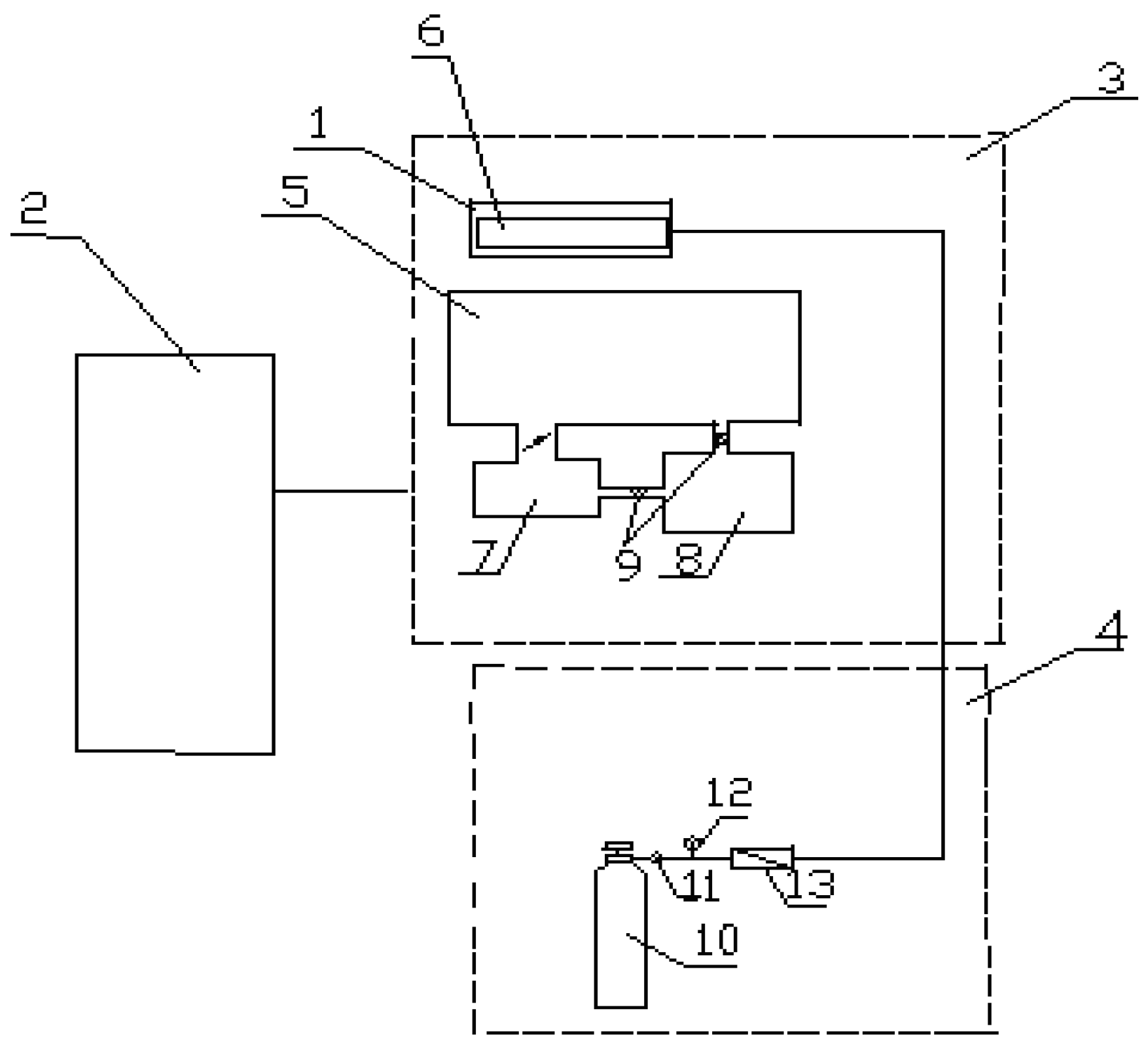
For hollow fiber membranes modification by low-temperature plasma the pilot scale setup (Figure 2) was used consisting of high frequency generator (HF generator), vacuum line, plasma gas feed system (air in our case), high voltage rectifier, high frequency plasmatron (a device for high frequency gas discharge) and control equipment.
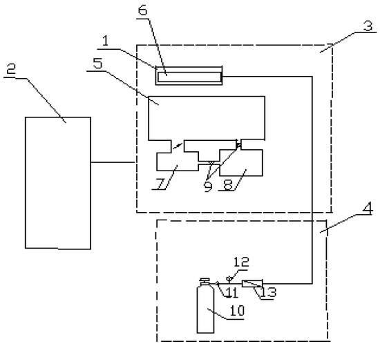
Figure 2.
Functional diagram of the pilot scale setup for hollow fibers modification. 1—plasmatron; 2—HF generator; 3—vacuum module; 4—gas supply system; 5—shutter; 6—hollow fiber membrane; 7—diffusion pump; 8—forvacuum pump; 9—valves; 10—gas pressure tank; 11—reducing valve; 12—standard pressure gauge; 13—variable area flow meter.
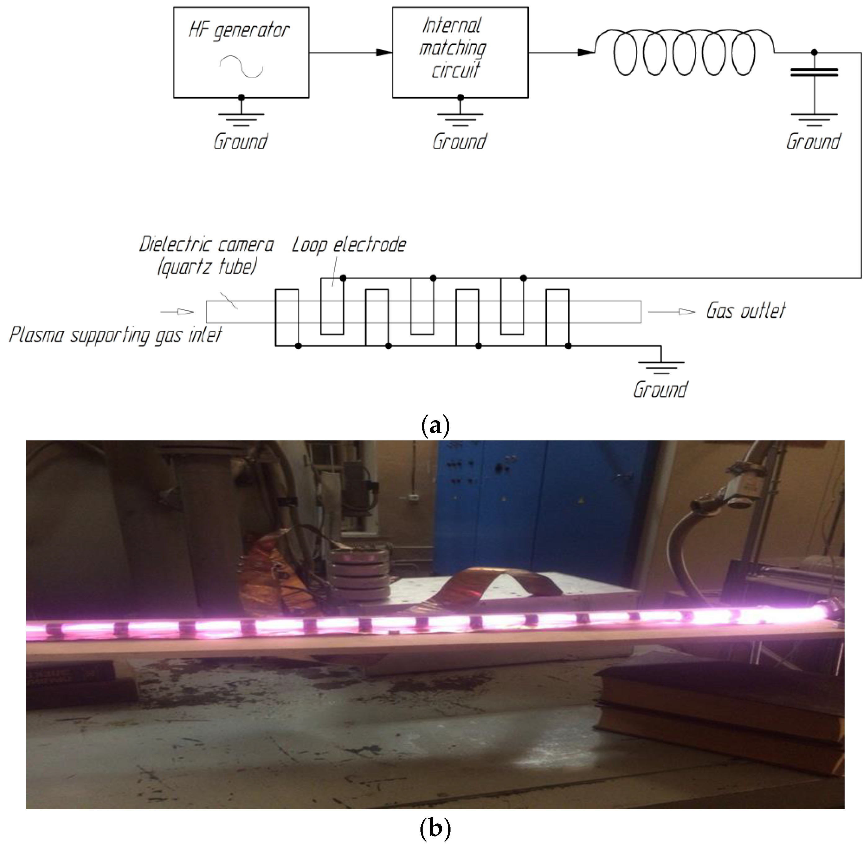
A device for high frequency gas discharge (Figure 3) is a dielectric gas-filled chamber close to dielectric stand-by with two parallel pad electrodes. Pad electrodes are connected with gas-filled chamber by loop electrodes with some of them plugged in the HF generator while the rest of them are grounded. Electrodes plugged in the HF generator as well as grounded electrodes are connected in parallel. Electrodes plugged in the HF generator are next but one interspersed with grounded electrodes. All loop electrodes are placed perimeter-wise outside of the dielectric gas-filled chamber providing plasma space distribution in the chamber. The electrode configuration used allows to stabilize electromagnetic component of the field and does not produce zero potential points in the bulk of dielectric gas-filled chamber. Therefore, plasma burns uniformly and stable in the chamber space.
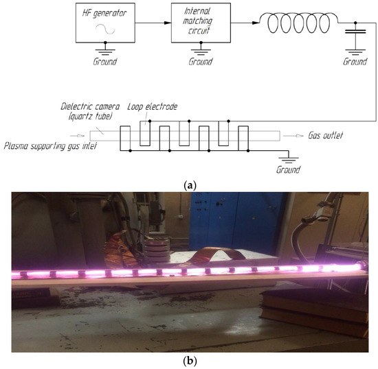
Figure 3.
(a) Gas discharge chamber electrode connection diagram; (b) Experimental gas discharge chamber for hollow fiber membranes treatment.
Hollow fiber membranes plasma modification was carried out as follows: first, dielectric gas-filled chamber was vacuumed; after that, 10 specimens of the membranes were placed into the camera followed by plasma supporting gas transmission at 110 Pa. Air was used as the plasma supporting gas, a mass flux of 0 to 0.24 g/s. Turning the HF generator on lets discharging plasma fill the dielectric chamber providing spatial uniformity and combustion stability. The duration of air plasma treatment was 3 min. Dielectric gas-filled chamber is made of quartz tube having high optical clarity, mechanical and thermal stability and also small dielectric quartz loss in operating band.
2.6. Fabrication of Composite Membranes on Highly-Permeable PSf Support with PTMSP Selective Layer
Composite PTMSP membranes on porous hollow fiber PSf support were fabricated as described in [21]. For composite membrane PTMSP top layer formation, the polymer (purchased from Gelest, Morrisville, PA, USA) solution in hexane was prepared. PTMSP concentration in the solution was 0.7 wt. %. Hexane was chosen as a solvent because it does not affect polysulfone stability, in particular, dimensions and geometry of hollow fiber support internal pores. For composite membrane fabrication, polymer solution was forced into hollow fiber lumen. Hollow fiber 30–40 cm long vertically fixed, PTMSP solution was put into fiber lumen by syringe pump. Inside volume being filled in (solid jet occurred at the outlet), fiber ends were pressurized and fiber was exposed under room temperature for 15 min. Porous hollow fiber supports were dry before coating. Membranes etched by Piranha were coated immediately after treatment and drying; specimens treated by plasma were coated two weeks after modification.
2.7. Contact Angle
Contact angle measurements for virgin (unmodified) and plasma treated specimens were carried out via the sessile drop technique using the Kruss DSA-30E goniometer (Kruss GmbH, Hamburg, Germany). The fiber was cut along an axis using razor blade, then flattened and placed onto preparation glass which, in turn, was put onto DSA-30E object table (Kruss GmbH, Hamburg, Germany) such that the camera captured the membrane—air interface. By using the dispenser (the syringe placed above the object table) a drop of distilled water was placed onto membrane inner side followed by camera image capture and processing with subsequent analysis and calculation.
2.8. Confocal Scanning Laser Microscopy
In order to prove changes occurring on the surface and within the hollow fiber membranes, after plasma treatment the confocal scanning laser microscopy analysis was performed (CSLM Olympus Lext OLS4000, Olympus America INC, Center Valley, PA, USA). After scanning, surface images of different points with various magnifications were obtained for each membrane specimen. Based on scanning data, surface micro relief characteristics were calculated. Surface roughness was the key characteristic. When determining the surface roughness main criteria were arithmetic average of the roughness profile (Ra) and roughness height (Rz). Roughness characteristics were evaluated based on all the scan points. For each specimen surface scans were obtained in 10 different points and then Ra and Rz values were averaged. The inner and outer surface micro relief determination was carried out by means of statistical processing by conventional CSLM Olympus Lext OLS4000 software in automatic mode for 10 different points.
2.9. Scanning Electron Microscopy (SEM)
SEM analysis was performed for membranes structure determination and precise calculation of their geometry characteristics. The specimens for SEM analysis were prepared as follows: a small piece of fiber (~10–15 cm) was placed into liquid nitrogen vessel, exposed for 3–5 min, then fixed by clips (such that the distance between clips was approx. 1 cm) and, finally, rapidly broken crosswise. The fragment obtained was orthogonally put onto the microscope object table. To enhance image contrast a thin layer of silver metal was sprayed on the fiber surface.
To obtain the micrographs the high resolution scanning electron microscope Zeiss LEO Supra 50 VP with microanalysis system INCA Energy+ Oxford (Carl Zeiss OIM GmbH, Oberkochen, Germany) was used. The microscope provides an opportunity to analyze non-conducting materials (such as polymers) under conditions of alternating pressure without pretreatment.
The scanning electron microscopy analysis was carried out under accelerating voltage 20 kV using 30 and 60 μm apertures. For charge neutralization on the specimen surface, the image capture was performed in low vacuum mode (nitrogen pressure 39 Pa). The images were captured by VP-detector and processed by Gwyddion software (Czech Metrology Institute, Brno, Czech Republic).
2.10. Fourier Transform Infrared Sprectoscopy
The possible changes of the membranes chemical composition were investigated by FTIR spectroscopy. The spectra registration was performed according to the reflection technique (attenuated total reflection method, ATR) using the IR microscope HYPERION-2000 associated with the Fourier transform IR spectrometer IFS-66 v/s Bruker (germanium crystal, resolution 2 cm−1, range 600–4000 cm−1) (Bruker Ltd., Coventry, UK). The technique enables to analyze the specimen surface layer of 0.45 μm thickness.
When samples were prepared for the measurement, it was important to avoid any contamination by non-volatile impurities from the environment. To this effect, before IR-spectra measurement, samples were conditioned in ethanol for 1 day followed by drying in vacuum for 1 day at temperature 40 °C.
2.11. X-ray Photoelectron Spectroscopy
The photoelectron spectra were collected on the photoelectron spectrometer “KRATOS AXIS ULTRA DLD” (Kratos Analytical, Manchester, UK) with spherical sector-field analyzer, sample heating option, ion guns and UV and X-ray sources. The experiments for the polysulfone polymers specimens surface analysis were carried out under ultrahigh vacuum 5 × 10⁻¹⁰–3 × 10⁻⁹ Torr using AlKα (mono) emission (energy resolution 0.48–0.6 eV, bond energies were calibrated against Ag 3d5/2 line).
Intense charging phenomena, shifting and widening peaks were observed in the specimens and because it was not possible to escape such phenomena by the neutralizator, the spectra were further calibrated against aliphatic C1s standard line at 284.7 eV and potential widening was taken into account when decomposing the peak.
2.12. Gas Permeance
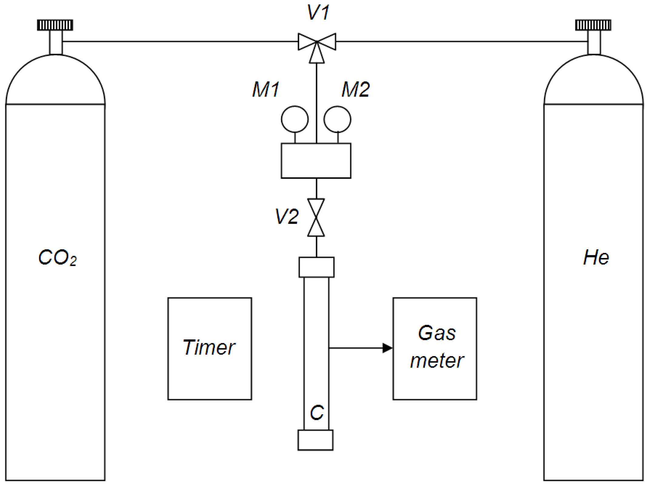
The membranes gas permeance was measured by the volumetric technique using the setup showed at Figure 4.
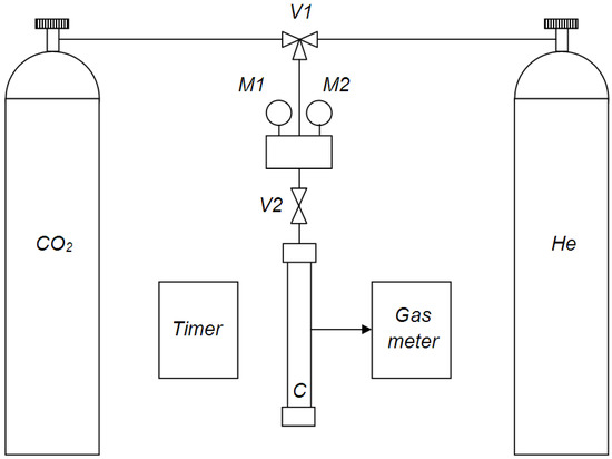
Figure 4.
Functional diagram of the laboratory setup for membranes gas permeance measurement.
Helium and carbon dioxide were used as test gases, as their molecular mass difference provides reliable way to determine Knudsen gas flow on the ideal selectivity value (permeability coefficients of individual gases ratio). Fiber specimen having length of 16 cm was fixed in the measurement cell C. Through the cross valve V1, one of the two gases (helium or carbon dioxide) got into system. Gas pressure in the tank was controlled by the M1 manometer and gas pressure in the system—by M2 manometer. Gas inlet into system was carried out by opening the V2 valve. The volumetric flux passed through the membrane was measured using gas meter and timer. The fibers gas permeance was measured under transmembrane pressure from 0.5 to 2 bar while permeate gas pressure was kept constant at 1 bar. Gas permeance measurements were carried out at room temperature (25 ± 2 °C). The membranes gas permeance values, P/l, were calculated according to the following equation:
where Q is the volumetric flux of the gas passed through the membrane, p is the transmembrane pressure and S is the membrane area.
The permeance tests results were reproducible for three membranes samples in case of each membrane type (unmodified membranes; membranes treated by air plasma; membranes treated by Piranha). Membranes performance was evaluated from the point of view of gas permeance and selectivity values. Based on these data, average pore size values were calculated by the Dusty Gas Model considering both Poiseuille and Knudsen flows contribution.
3. Results and Discussion
3.1. Scanning Electron Microscopy
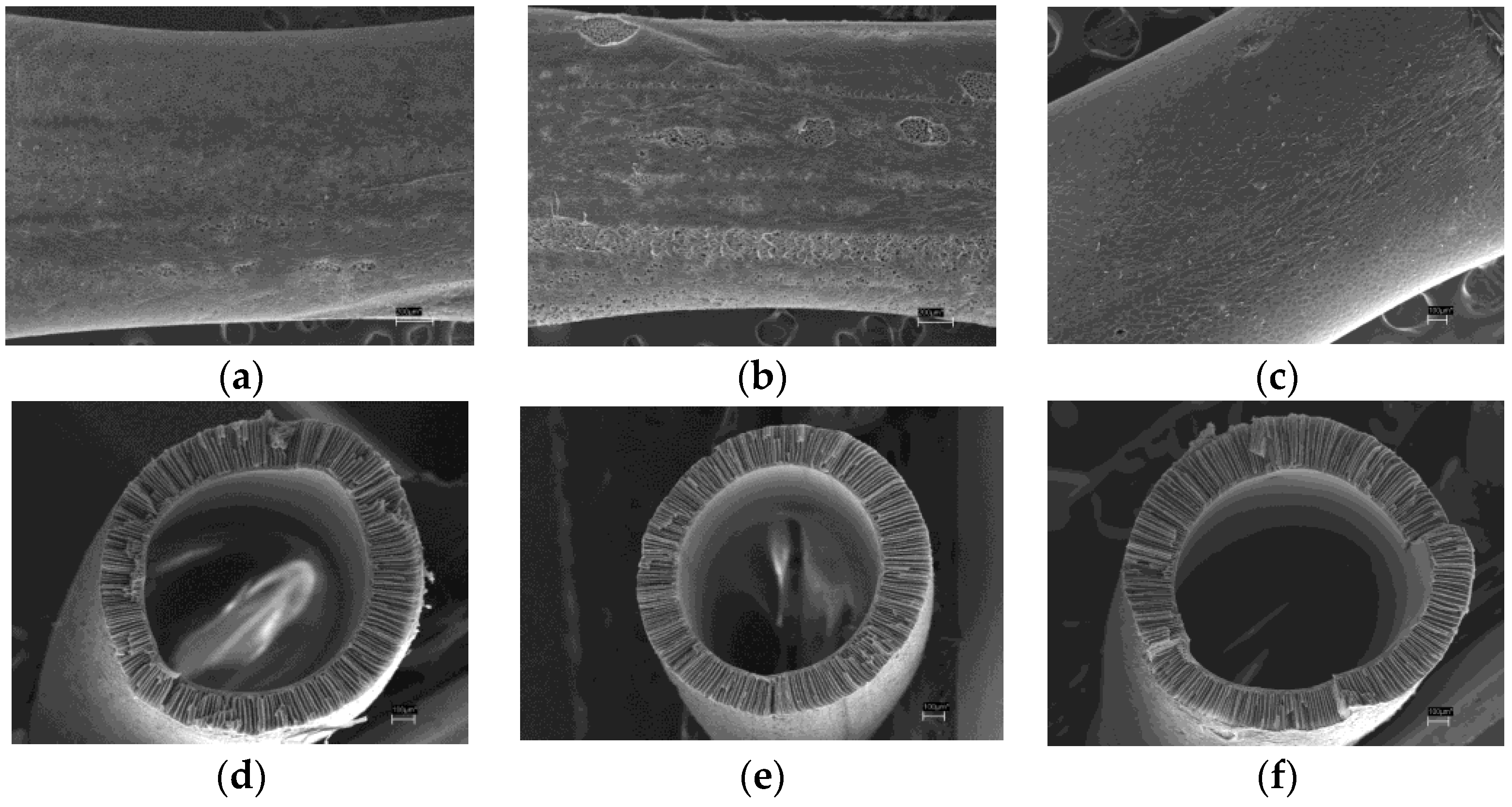
The cross section and outer surface micrographs were obtained for both virgin and treated HF membranes. Outer surface of the virgin HF membrane, as well as air plasma and piranha mixture treated membranes images are shown in Figure 5a–c, respectively. It is clear that air plasma modified fiber has macroscopic defects on the outer surface and it proves that plasma does affect the membrane material. On the other hand, the fiber modified by piranha mixture does not seem to differ from the unmodified specimen. Figure 5c,d) shows cross section images of the virgin and treated hollow fibers. It can be observed that modification does not affect the membrane internal macrostructure. The fibers have similar geometrical parameters like outer and inner diameter values and wall thickness. The outer diameter value is 1.52–1.55 mm, the inner is 1.03–1.05 mm.
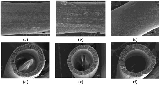
Figure 5.
Image segment of the fiber outer surface, 100× magnification: (a) virgin membrane; (b) air plasma treated membrane; (c) piranha mixture treated membrane; fiber cross section image, 130× magnification: (d) virgin membrane; (e) air plasma treated membrane; (f) piranha mixture treated membrane.
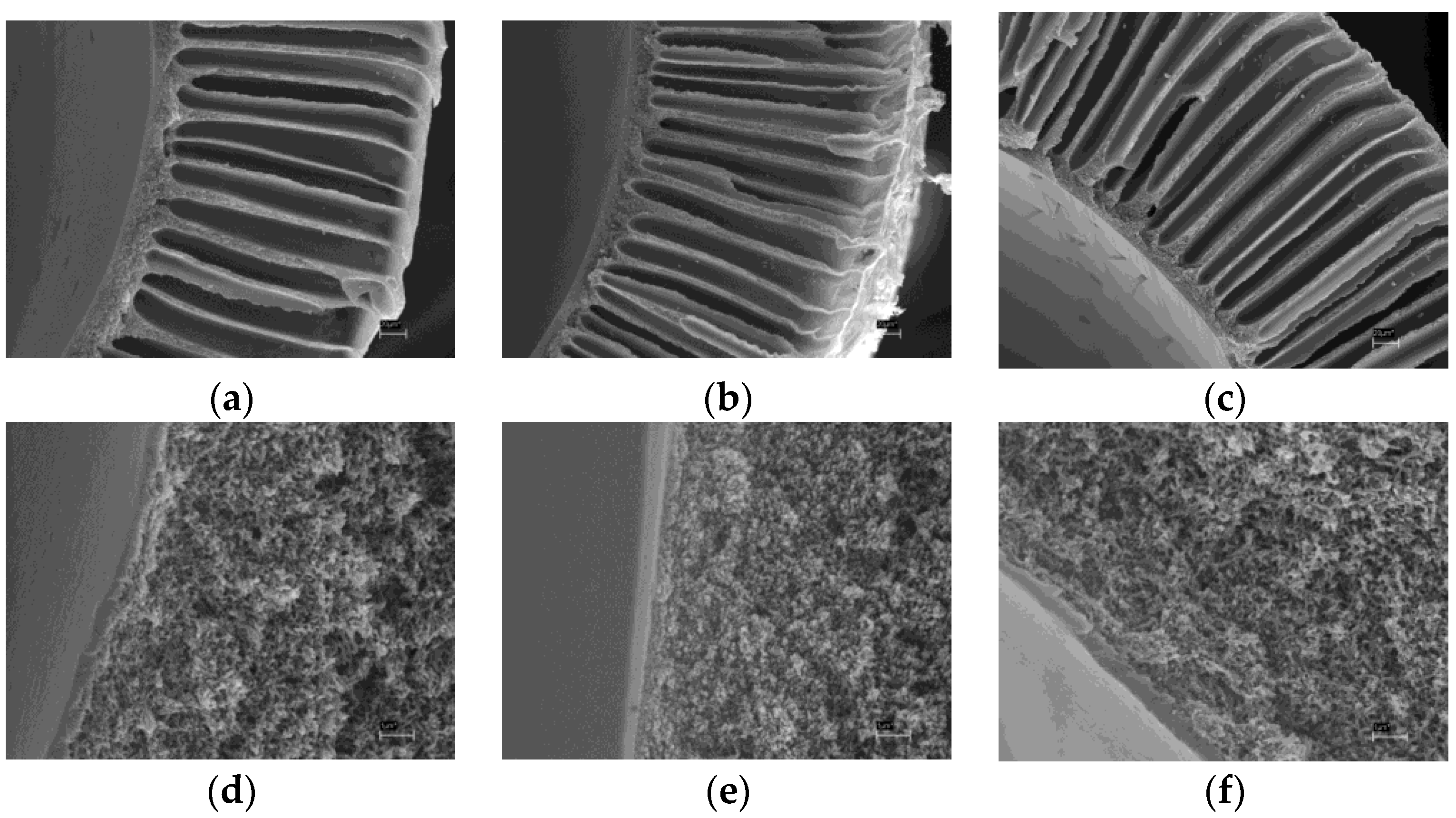
Figure 6a–c shows cross section segments of the HF membranes described above. The hollow fibers asymmetric structure can be analyzed in detail: it is evident that the three specimens have thin dense layer from the lumen side and thick layer with finger-like pores (macrovoids) from the shell side.
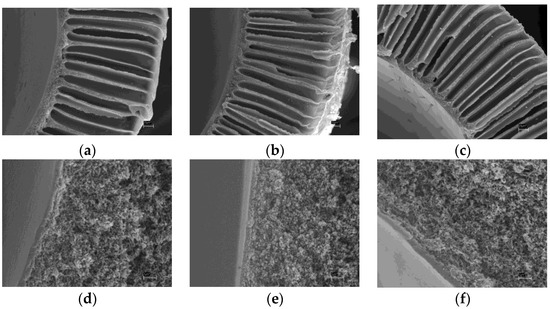
Figure 6.
Image segment of the hollow fiber cross section, 350× magnification: (a) virgin membrane; (b) air plasma treated membrane; (c) piranha mixture treated membrane; image segment of the fiber cross section: selective layer + transition layer part, 20,000× magnitude: (d) virgin membrane; (e) air plasma treated membrane; (f) piranha mixture treated membrane.
In order to examine hollow fiber asymmetric structure in detail, enlarged (20,000×) images of the membranes cross section at the inner surface were obtained for both unmodified and treated specimens (Figure 6d). It can be seen that in fiber bulk all membranes examined have sponge porous structure while at the interface of the hollow fiber lumen the dense and homogeneous skin layer of approx. 0.5 μm widths can be observed. The selective layer appears to be uniform and defect-free for both unmodified and treated membranes. Therefore, air plasma as well as piranha mixture treatment does not damage inner selective layer, which defines the HF membrane properties.
Due to the fact that micrographs resolution for polymer objects does not exceed 0.1 μm, it is not possible to deduce skin layer porous structure alteration from the SEM data. Other physical and chemical methods like IR spectroscopy, contact angle measurement, CSLM and gas permeance measurement should be used.
3.2. Fourier Transform IR Spectroscopy
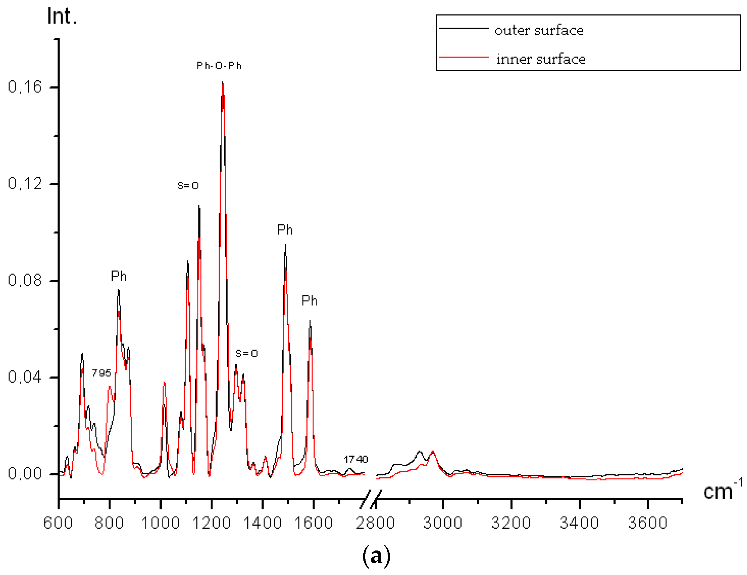
All membranes were analyzed through IR spectroscopy. Figure 7a shows inner and outer surfaces spectra for initial PSf membranes.
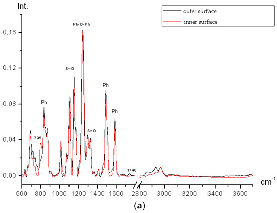
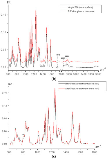
Figure 7.
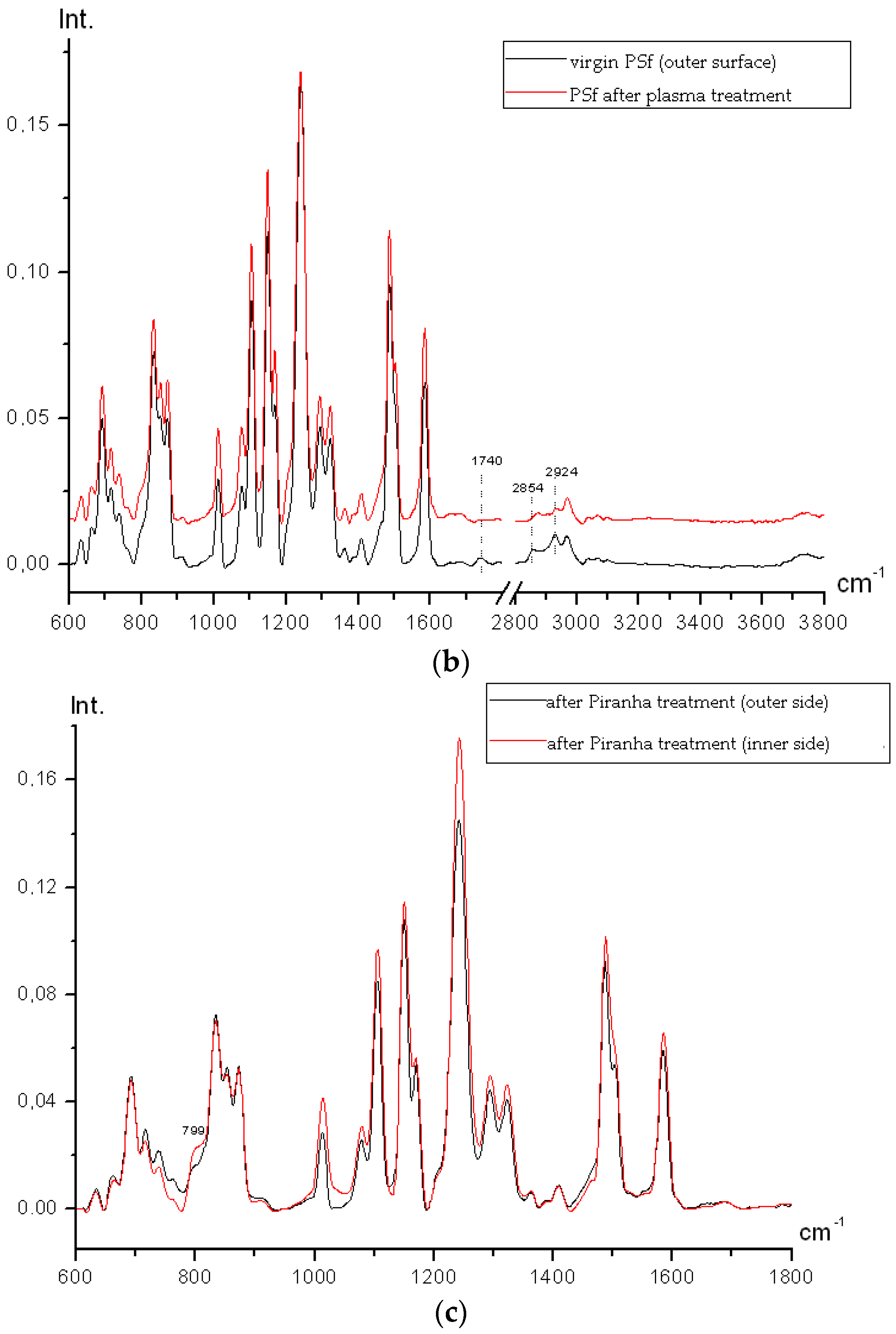
(a) spectra comparison for outer and inner sides of virgin PSf membrane; (b) the outer surface IR spectra comparison for virgin and air plasma treated PSf hollow fiber membranes; (c) IR spectra comparison for inner and outer sides of the PSf hollow fiber membrane treated by piranha mixture (hydrogen peroxide and sulfuric acid).
The spectra are almost identical; conformational difference (relative band intensities slightly vary) is present. The 1740 cm−1 bands (C=O) and 2800–2960 cm−1 (saturated CH) are present but the impurity amount is not above 0.01% which may be accounted for by the presence of residual solvent (N-methylpyrrolidone) which is used in the PSf membranes spinning.
An excess band 795 cm−1 (may be referred to C–Cl bond) is present on the inner side of the membrane. It is likely that chlorine containing groups occur on the polymer chain sides because the polymer is synthesized by interaction between bisphenol A alkali salt and 4,4′-dichlorodiphenyl sulfone. Trace amount of porogen polyethylene glycol is not observed neither inside the hollow fiber nor outside.
After plasma treatment all impurities disappear from both inner and outer sides; all bands, especially in outer spectrum, slightly increase in intensity because the majority of bands in PSf polarize (Figure 7b). It proves the fact that air plasma influences the membrane surface.
Figure 7c shows that after hydrogen peroxide and sulfuric acid mixture treatment no oxidation occurs on either side of the membrane. The inner and outer sides differ only in C–O–C bonds conformation (relative intensities vary). On the inner side the 799 cm−1 band (C–Cl) appears again, but its intensity is lower than that in the inner side spectra of the initial film, which indicates more gentle membrane treatment in comparison to the air plasma modification.
Consequently, according to the IR spectroscopy data, both chemical and plasma-chemical modification do not lead to significant changes in the polymer chemical structure; it is important for membrane stability in terms of membrane mechanical properties and chemical resistance.
To analyze the membrane surface properties change, the XPS, contact angle measurement and CSLM techniques were used.
3.3. X-ray Photoelectron Spectroscopy
Figure 8 shows base O1s, C1s, S2p and 2s lines of the virgin PSf membrane surface XPS spectrum. Trace impurities of Na, Ca, Si (Si2s and Si2p) and nitrogen are present which can be accounted for by residual solvent (N-methylpyrrolidone) and external non-solvent (tapwater) presence.

Figure 8.
XPS spectra: virgin PSf membrane (a); PSf membrane surface after air plasma treatment (b); PSf membrane surface after piranha mixture treatment (c).
As can be seen from Figure 8, for the specimen modified by air plasma the same elements were detected as for the unmodified membrane.
The surface XPS spectrum of the PSf membrane etched by piranha mixture differs from those of two another specimens (Figure 8c). Here, no observable sodium and calcium traces are present, nitrogen amount is reduced and phosphorus traces appear. Presumably, this is due to the effect of the sulfuric acid which binds metals ions to salts which, in turn, pass into solution. Phosphorus traces may be accounted for by phosphates presence in the hydrogen peroxide solution (37 wt. %).
The efficiency of plasma and chemical treatment was estimated by comparison of oxygen atoms concentration on the PSf membrane surface comparison (Table 1).

Table 1.
Oxygen atoms concentration on the PSf membrane surface after air plasma and piranha mixture etching.
Oxygen concentration ranges from 18.3 to 21.1 at % (exclusively of hydrogen which cannot be detected by this technique) which exceeds oxygen concentration in PSf (12.5 at %). Presumably, this is due to the surface adsorption of various oxygen containing compounds (N-methylpyrrolidone, water, salts, oxides etc.) during the hollow fiber membranes spinning. For the membrane modified by air plasma, surface oxygen concentration is maximum—21.1 at %. The minimum oxygen concentration is that of the membrane etched by hydrogen peroxide and sulfuric acid mixture. This contradiction may be accounted for by impurities washout from the membrane surface while treating it by the piranha mixture, which is confirmed by the fact that metal (salts) peaks disappear and nitrogen (N-methylpyrrolidone) peak intensity decreases. The reduced oxygen content after piranha treatment showed that the membrane has a composition more close to the polysulfone.
3.4. Contact Angles
Measuring the contact angle is the conventional technique for determining the membrane material hydrophobic or hydrophilic properties. The technique provides the ideal surface wetting data; in most cases, the contact angle values appear to be slightly distorted because of surface porosity, microroughness, etc. In order to estimate the air plasma and piranha mixture effects on the PSf hollow fiber membranes wettability and surface energy, contact angle values for both water and ethylene glycol were measured. Such test liquids are widely used for membranes surface energy determination because surface energy components of both liquids are well known and widely described in the literature [22]. When solid body/liquid interfaces are in contact, thermodynamic equilibrium is described by Young equation:
where , and are liquid-vapor system surface tension, polymer surface energy and solid body/liquid interface surface tension, respectively. Because solid body surface tension cannot be measured directly, second equation should be used to estimate the free surface energy value, which, in turn, can be determined by the Owens-Wendt interfacial interaction model [23]. The procedure is based on the general theory of the adhesion work between solid and liquid phases in which their interaction is described in terms of the polar and nonpolar (dispersive) components contribution [24]. The Owens-Wendt procedure allows determining the surface energy as polar and dispersive components sum using two different test liquids. The relation between surface energy and equilibrium contact angle of the liquid phase placed onto solid phase is derived from the following equation [25]:
where d and p superscripts relate to the dispersive and polar components of the liquid surface energy and the membrane surface energy .
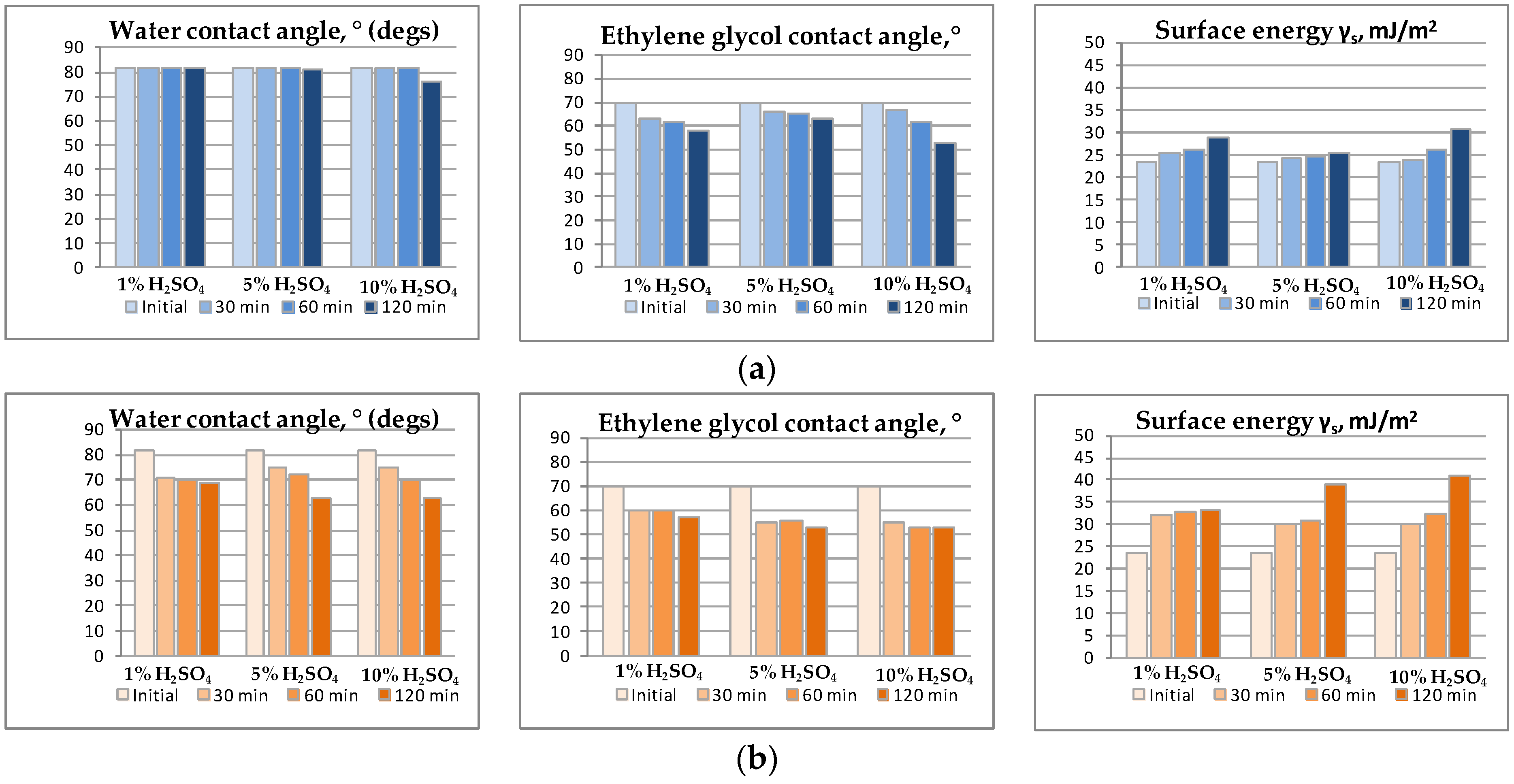
During the PSf membranes etching by hydrogen peroxide and sulfuric acid mixture such process parameters as treatment time, sulfuric acid concentration in the hydrogen peroxide solution and etching mixture temperature were varied. The results reflect the parameters effect and are shown in the form of diagram in the Figure 9a,b. It can be seen that the longer the treatment time, the stronger the membranes affinity for test liquids: when treatment time is increased from 30 min to 2 h, contact angle value decrease is observed for almost all specimens (except for treatment under room temperature 23 ± 2 °C). Moreover, the specimens surface energy increases up to 2 times which indicates the PSf membranes properties and morphology change.
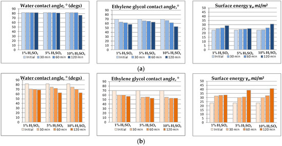
Figure 9.
Properties of the membranes etched by hydrogen peroxide and sulfuric acid mixture under 23 °C (a) and 50 ± 2 °C (b).
Increase in sulfuric acid (etching agent) concentration in an aqueous hydrogen peroxide solution has less effect on the surface wettability which can be seen from Figure 9a. The effect is more visible for the ethylene glycol (Figure 9b). Nevertheless, etching under elevated temperature (50 ± 2 °C) shows that H2SO4 concentration rise also enhances the membranes hydrophilic properties but the difference between 5 wt. % and 10 wt. % H2SO4 solutions is negligible at treatment times lower than 120 min. Therefore, from the viewpoint of practical use, 5 wt. % H2SO4 solution appears to be more reasonable.
Finally, etching solution temperature plays a key role. When comparing data shown in Figure 9a,b, it can be observed that water contact angle change is small to negligible when etching solution has room temperature, while under elevated temperature (50 ± 2 °C) contact angle values decrease drastically. Similar alteration is observable for free surface energy which, in the case of 5 wt. % sulfuric acid solution, increases from 26 to 39 mJ/m2 with temperature rise from 23 to 50 °C. Probably, increasing the temperature leads to chemical transformation accelerating on the membranes surface.
Taking into account all the results obtained for hydrophilization by piranha mixture, for further research and characterization membranes treated by 5 wt. % H2SO4 solution in hydrogen peroxide solution under 50 ± 2 °C for 120 min were chosen.
Air plasma modification also affects the membranes surface properties. In [25] it is shown that the active components generated in plasma may activate upper molecular layers of membrane surface, therefore increasing their hydrophilicity without producing changes in the membrane bulk. Under bombardment by plasma ions radicals are produced which may interact with gas molecules.
Average water and ethylene glycol contact angle values as well as free surface energy values for unmodified and plasma treated PSf membranes are given in Table 2.

Table 2.
Contact angle θ and surface energy γS values for water and ethylene glycol for virgin and air plasma treated membranes.
It can be seen that membrane wettability also increases after treatment. Surface free energy of the treated membrane is approx. 1.5 times higher than that of unmodified membrane which shows that membrane surface properties do change.
It should be remarked that the membranes modified by air plasma show best hydrophilic properties and higher surface energy value of all membranes studied: after plasma treatment, the water contact angle value was 59° and the free surface energy value was 42 mJ/m2; both values indicate better hydrophilicity than those of Piranha modified membranes (θav (H2O) = 63°, = 39 mJ/m2, as given at Figure 8b) and those of the virgin membranes (θav (H2O) = 81°, = 24 mJ/m2, as given in Table 2).
3.5. Confocal Laser Microscopy
Confocal laser microscopy is used for surface morphology analysis [26,27] as well as for polymer membranes asymmetric porous structure analysis [28].
Figure 10 shows confocal scanning laser microscopy images of membranes outer surface: a—virgin membrane, b—membrane treated by air plasma, c—membrane treated by piranha mixture.

Figure 10.
Hollow fiber membrane outer surface microrelief: (a) reference sample; (b) membrane treated by air plasma; (c) membrane treated by piranha mixture (2000× magnification).
It can be seen that images obtained substantially differ, which indicates that air plasma and piranha mixture affect the membrane surface in different ways. Modification leads to surface morphology change which is important in terms of wetting phenomena. To quantitatively estimate the modification effect on the membranes morphology, average roughness height (Rz) and arithmetic average of the roughness profile (Ra) values were used (Table 3). Data obtained show that membrane treatment by air plasma and piranha mixture leads to surface relief change. For the virgin membrane, arithmetic average of the roughness profile (Ra) is 0.15 µm and roughness height (Rz) is 0.68 µm. Air plasma treatment causes minor morphology changes and results in Ra and Rz values decrease to 0.11 and 0.49 µm, respectively. Membrane treated by piranha mixture has intermediate Ra and Rz values: 0.13 and 0.62 µm, respectively. Therefore, smoothing of surface heterogeneity is observed, and for air plasma treated membranes, their surface becomes less rough.

Table 3.
Test data for the experimental samples.
It is known that surface roughness decrease can significantly affect the surface wettability [29]. Most likely, relief change is one of the factors leading to water and ethylene glycol contact angles decrease on the hollow fibers surface.
3.6. Gas Permeance
The most important membranes characteristic is their permeance which depends on selective layer porous structure. All membranes examined were characterized by means of gas permeance technique using helium and carbon dioxide as operating fluids, as their molecular mass difference provides reliable way to estimate gas flows mode and transport pores sizes. The results are summarized in Table 4.

Table 4.
Gas permeance values for hollow fiber PSf membranes examined.
It is shown that for both unmodified and treated membranes high CO2 permeance values (2.1–3.3 × 10⁵ GPU (Gas Permeance Units)) are observed. The ideal He/CO2 selectivity value for unmodified membranes is 2.3, which corresponds to mixed gas flow mode between Poiseuille (α = 1) and Knudsen (α = 3.3) flows.
Average pore size values were estimated based on Dusty Gas Model (DGM), considering both Poiseuille and Knudsen flows contribution [30]. Average pore size values for both unmodified and treated membranes are given in Table 4.
For air plasma treated membranes, higher gas permeance values (principally for CO2) than for unmodified membranes are observed; ideal He/CO2 selectivity decreases to 1.5. Calculated pore size for such membranes is 34 nm which is 1.5 times higher than that of the virgin membrane (24 nm). Gas permeance increase and selectivity decrease after modification results from transport pores enlarging due to air plasma etching.
For membranes modified by piranha mixture, no significant gas permeance and selectivity change are observed; it is evidence that only membrane surface is modified without affecting transport pores which may be situated in the membrane bulk. It is proved by pore size calculation data based on gas permeance tests results: calculated pore size for membrane modified by piranha mixture (23 nm) corresponds to that of the virgin membrane (24 nm).
It can be concluded that porous membranes characterization by means of gas permeance measurement using gas couple He/CO2 provides an opportunity to estimate average transport pores size as well as to compare membranes modified by various techniques. The selectivity values obtained are lower than those corresponding to ideal Knudsen flow regime. However, it should be mentioned that we are considering selectivity values of the membranes employed as porous supports for composite membranes fabrication. Such supports allow to obtain high gas permeance values; as for composite membranes, their selectivity is not determined by the selectivity of the support itself, but by the top layer polymer (PTMSP) selectivity.
3.7. Composite Membranes Fabrication
The membrane treated by air plasma was chosen as a porous support for fabricating composite hollow fiber membranes with thin PTMSP dense layer. It has highest oxygen-containing functional groups concentration and highest surface energy (more phobic to hydrocarbons) and also high CO2 permeance (3.3 × 10⁵ GPU) in comparison with unmodified membranes.
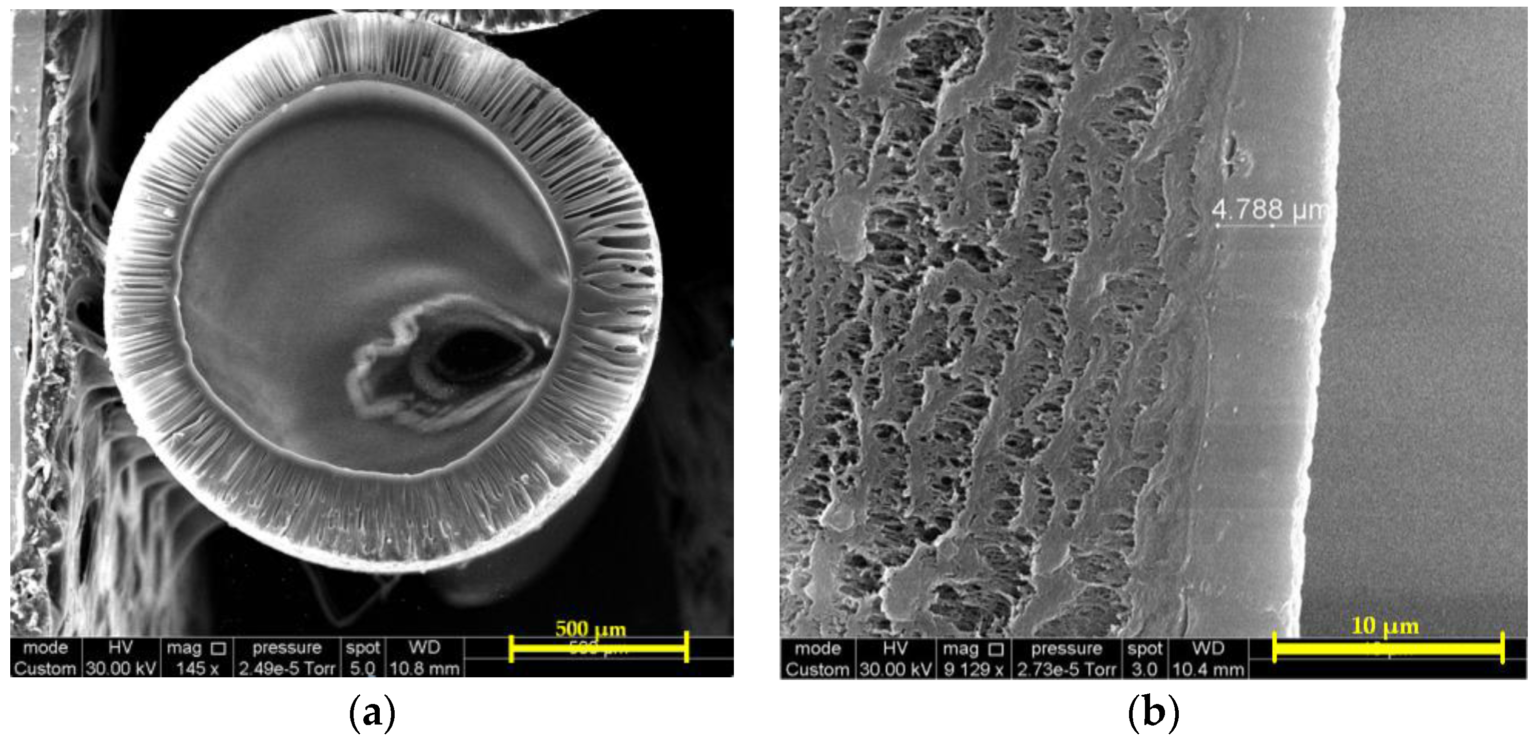
Figure 11 shows SEM micrographs of the composite PTMSP membrane on the porous PSf support modified by air plasma. It can be seen that the membrane consists of two phases: the first is PSf hollow fiber having asymmetric porous structure and the second is PTMSP selective layer of 4.8 ± 0.2 μm width.
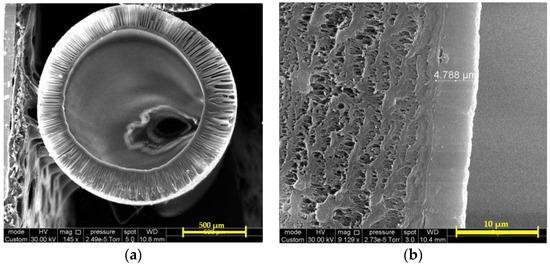
Figure 11.
SEM micrographs: (a) the hollow fiber cross section; (b) PTMSP selective layer on the porous PSf support modified by air plasma (cross section fragment).
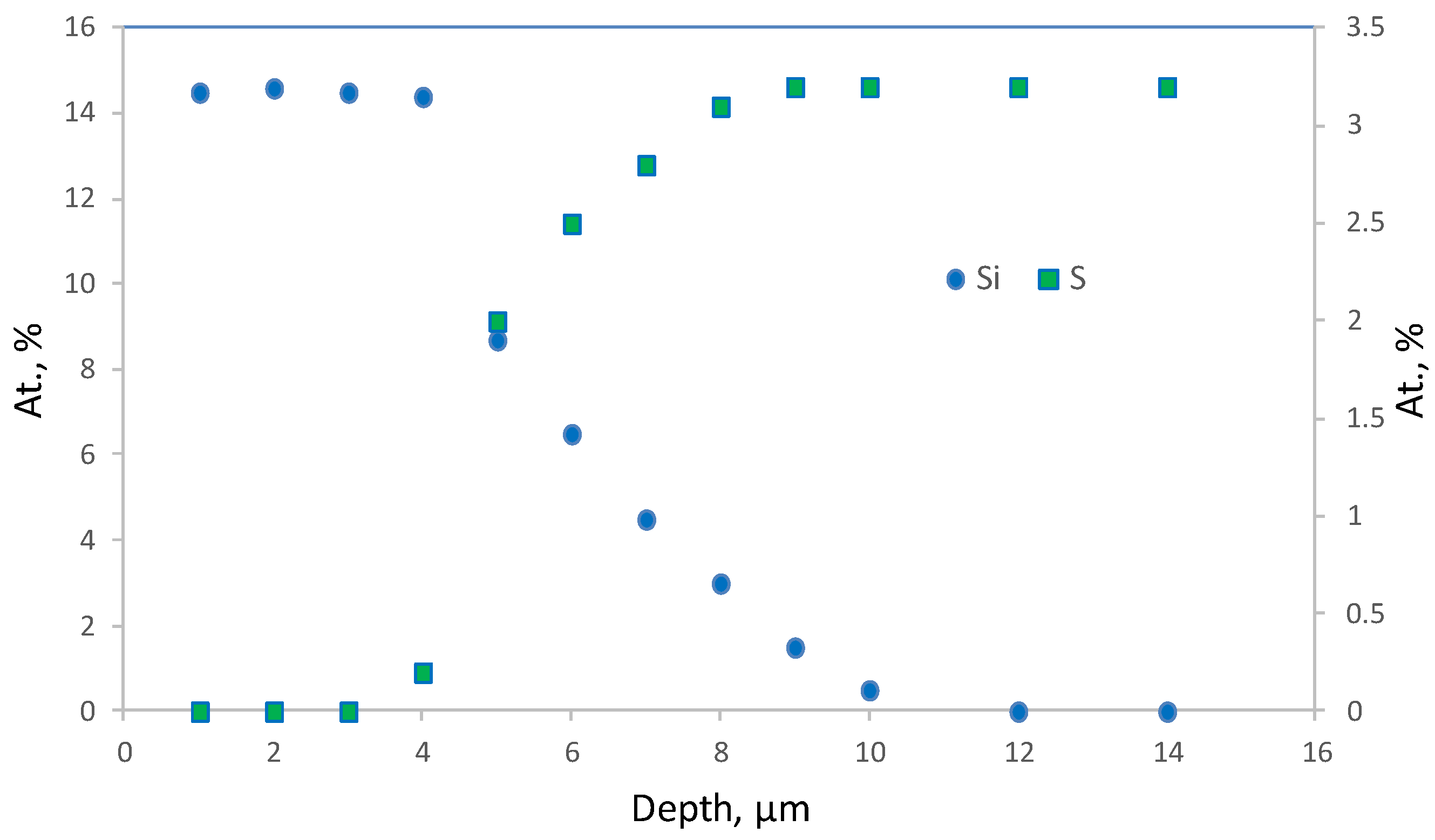
Figure 12 shows Si and S elemental profiles for selective top layer fragment (Figure 11b) obtained by the electron probe microanalysis (EPMA) technique. It can be seen that silicon concentration is maximum on the membrane surface and decreases with probing depth increase. It is demonstrated that significant amount of silicon (and therefore PTMSP) penetrates into the membrane up to 10 μm.
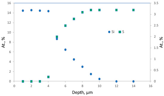
Figure 12.
Atomic Si and S fraction dependence on composite PTMSP/PSf membrane selective layer scanning depth. The curve is obtained by EPMA technique.
On the membrane surface, silicon concentration is 14.5 at % (exclusively of hydrogen, as it cannot be detected by this technique), which corresponds to silicon concentration in PTMSP. Sulfur concentration increases with probing depth and reaches 3.2 at %, the value typical for PSf. The PTMSP selective layer thickness can be defined by the inflection point of the concentration-probing depth curve. The calculated thickness value 4.5 ± 0.5 μm (measurement error is defined by scanned surface size: 1 μm) is in good agreement with noted above value obtained by SEM (4.8 ± 0.2 μm). Taking into account the error of the method, it can be concluded that PTMSP penetrates into support pores to the depth of 6.5 ± 0.5 μm. On the one hand, it has positive effect on the selective layer cohesion with the support, one the other, it may lead to gas permeance loss.
To estimate the contribution of the PTMSP selective layer, PTMSP layer in the support pores and of the support itself in the cumulative permeance value, the calculation was performed based on Henis and Tripodi [31] model:
where P/l and P3/l3 are the integral gas permeance values of the composite membrane and the support, respectively (GPU); P1 = P2—gas permeability coefficient of the selective layer material (PTMSP) (GPU); l1 and l2—thickness of the selective layer and the layer penetrated into support pores, respectively (μm); ε—surface porosity of the PSf hollow fiber lumen side, i.e., ratio of pores area to the whole membrane area.
For calculation previously published [16] CO2 permeability coefficients for PTMSP were used; other calculation parameters were as follows: PTMSP selective layer thickness l1 = 4.5 μm; PTMSP penetrated into pores layer thickness 6.5 μm (Figure 11); air plasma treated PSf support and the composite membrane CO2 permeance as given in Table 4 and Table 5. The calculated surface porosity value for hollow fiber lumen surface is 41%.

Table 5.
Gas permeance of composite hollow fiber membranes with thin PTMSP dense layer on the inner surface of air plasma treated porous PSf support.
Henis-Tripodi computation allowed to determine that 77.35% of gas transport resistance is driven by the PTMSP layer which penetrated into the support pores; the contribution of the support and the selective layer is 0.45% and 22.2%, respectively. It was shown [16] that for similar PSf membranes (not modified by air plasma) surface porosity is 0.4%. Composite PTMSP membranes on non-modified PSf supports have CO2 permeance 96 GPU with 98.6% PTMSP layer in the support pores contribution in the overall mass transport resistance. Therefore, surface modification of the PSf membranes by air plasma allows for 2 order surface porosity increase, which, in turn, provides an opportunity to obtain composite membranes having the permeance order of magnitude greater than that of the membranes with non-modified support. It can be concluded that such membranes are promising for employing them in gas-liquid membrane contactors.
4. Conclusions
In this work, the methods of hollow fiber PSf membranes modification by low temperature air plasma and piranha (H2O2 + H2SO4) mixture were developed. It was shown that modification does not lead to the membrane fine-porous selective layer destruction. The IR spectroscopy data prove that both chemical (piranha mixture) and plasma-chemical (air plasma) modification techniques do not cause noticeable change in the polymer chemical structure which is important from the point of view of the membrane performance properties stability.
The membranes modification results in the selective layer surface roughness decrease. Plasma treatment enables to reduce the arithmetic average of the roughness profile to 0.11 μm and the average roughness height to 0.49 μm. Surface roughness decrease results in water and ethylene glycol contact angle values decline on the modified hollow fibers surface. Furthermore, the fibers surface energy increases 2 times which indicates that PSf membranes properties and morphology do change.
It was shown that modified membranes have higher CO2 permeance (3.3 × 10⁵ GPU) than that of the virgin PSf membranes (2.1 × 10⁵ GPU). The ideal He/CO2 selectivity for the unmodified membranes is 2.3 which indicates mixed gas flow mode. The average pore size of the air plasma treated membranes calculated based on the gas permeability data by the Dusty Gas Model (34 nm) is 1.5 times higher than that of the virgin membrane (24 nm). The gas permeability increase and He/CO2 selectivity decrease after modification results from transport pores etching.
For membranes modified by piranha mixture no significant change in gas permeability, selectivity or calculated average pore size is observed, which indicates that only membrane surface is affected without involving transport pores in the membrane bulk.
The selective layer etching by air plasma leads to 2 order surface porosity increase which provides an opportunity to obtain PTMSP-based composite membranes having the permeability order of magnitude greater than that of the membranes with non-modified support. This, in turn, makes such membranes promising for employing them in gas-liquid membrane contactors.
Acknowledgments
This work was carried out in TIPS RAS with a financial support from Russian Science Foundation (RSF project no. 14-49-00101). Ilya. L. Borisov, Anna. A. Ovcharova, Stepan. D. Bazhenov, Alexandr. V. Bildyukevich and Vladimir. V. Volkov acknowledge the financial support of RSF.
Author Contributions
Ilya Borisov carried out PSf hollow fiber membranes chemical modification and wrote the paper, Anna Ovcharova fabricated the membranes, Danila Bakhtin provided SEM micrographs, Stepan Bazhenov performed gas permeance measurements, Alexey Volkov and Vladimir Volkov analyzed the data, Galina Bondarenko provided IR spectroscopy data, Rustem Gallyamov carried out membranes plasma treatment, Rustem Ibragimov carried out plasma treated specimens characterization, Rais Mozhchil provided X-ray photoelectron spectroscopy data, Alexandr Bildyukevich developed membranes fabrication regimes and analyzed the data.
Conflicts of Interest
The authors declare no conflict of interest.
References
- Schott, K. Handbook of Industrial Membranes, 2nd ed.; Elsevier: New York, NY, USA, 1997; pp. 187–269. [Google Scholar]
- Khulbe, K.C.; Feng, C.; Matsuura, T. The Art of Surface Modification of Synthetic Polymeric Membranes. J. Appl. Polym. Sci. 2010, 115, 855–895. [Google Scholar] [CrossRef]
- Korminouri, F.; Rahbari-Sisakht, M.; Matsuura, T.; Ismail, A.F. Surface Modification of Polysulfone Hollow Fiber Membrane Spun Under Different Air-Gap Lengths for Carbon Dioxide Absorption in Membrane Contactor System. Chem. Eng. J. 2015, 264, 453–461. [Google Scholar] [CrossRef]
- Plisko, T.V.; Bildyukevich, A.V.; Volkov, V.V.; Osipov, N.N. Formation of Hollow Fiber Membranes Doped with Multiwalled Carbon Nanotube Dispersions. Pet. Chem. 2015, 55, 318–332. [Google Scholar] [CrossRef]
- Chu, L.Y.; Wang, S.; Chen, W.M. Surface Modification of Ceramic-Supported Polyethersulfone Membranes by Interfacial Polymerization for Reduced Membrane Fouling. Macromol. Chem. Phys. 2005, 206, 1934–1940. [Google Scholar] [CrossRef]
- Liubimova, E.S.; Bildyukevich, A.V.; Melnikova, G.B.; Volkov, V.V. Modification of Hollow Fiber Ultrafiltration Membranes by Interfacial Polycondensation: Monomer Ratio Effect. Pet. Chem. 2015, 55, 795–802. [Google Scholar] [CrossRef]
- Cacho-Bailo, F.; Catalán-Aguirre, S.; Etxeberría-Benavides, M.; Karvan, O.; Sebastian, V.; Téllez, C.; Coronas, J. Metal-organic framework membranes on the inner-side of a polymeric hollow fiber by microfluidic synthesis. J. Membr. Sci. 2015, 476, 277–285. [Google Scholar] [CrossRef]
- Korikov, A.P.; Kosaraju, P.B.; Sirkar, K.K. Interfacially polymerized hydrophilic microporous thin film composite membranes on porous polypropylene hollow fibers and flat films. J. Membr. Sci. 2006, 279, 588–600. [Google Scholar] [CrossRef]
- Steen, M.L.; Jordan, A.C.; Fisher, E.R. Hydrophilic Modification of Polymeric Membranes by Low Temperature H2O Plasma Treatment. J. Membr. Sci. 2002, 204, 341–357. [Google Scholar] [CrossRef]
- Fernández-Barquín, A.; Casado-Coterillo, C.; Palomino, M.; Valencia, S.; Irabien, A. Permselectivity improvement in membranes for CO2/N2 separation. J. Membr. Sci. 2016, 157, 102–111. [Google Scholar] [CrossRef]
- Volkov, A.V.; Bakhtin, D.S.; Kulikov, L.A.; Terenina, M.V.; Golubev, G.S.; Bondarenko, G.N.; Legkov, S.A.; Shandryuk, G.A.; Volkov, V.V.; Khotimsky, V.S.; et al. Stabilization of gas transport properties of PTMSP with porous aromatic framework: Effect of annealing. J. Membr. Sci. 2016, 517, 80–90. [Google Scholar] [CrossRef]
- Bildyukevich, A.V.; Plisko, T.V.; Liubimova, A.S.; Volkov, V.V.; Usosky, V.V. Hydrophilization of polysulfone hollow fiber membranes via addition of polyvinylpyrrolidone to the bore fluid. J. Membr. Sci. 2017, 524, 537–549. [Google Scholar] [CrossRef]
- Gancarz, I.; Poźniak, G.; Bryjak, M. Modification of Polysulfone Membranes 1. CO2 Plasma Treatment. Eur. Polym. J. 1999, 35, 1419–1428. [Google Scholar] [CrossRef]
- Wavhal, D.S.; Fisher, E.R. Modification of Polysulfone Ultrafiltration Membranes by CO2 Plasma Treatment. Desalination 2005, 172, 189–205. [Google Scholar] [CrossRef]
- Gancarz, I.; Poźniak, G.; Bryjak, M. Modification of Polysulfone Membranes: 3. Effect of Nitrogen Plasma. Eur. Polym. J. 2000, 36, 1563–1569. [Google Scholar] [CrossRef]
- Castro Vidaurre, E.F.; Achete, C.A.; Gallo, F.; Garcia, D.; Simão, R.; Habert, A.C. Surface Modification of Polymeric Materials by Plasma Treatment. Mat. Res. 2002, 5, 37–41. [Google Scholar] [CrossRef]
- Kim, K.S.; Lee, K.H.; Cho, K.; Park, C.E. Surface Modification of Polysulfone Ultrafiltration Membrane by Oxygen Plasma Treatment. J. Membr. Sci. 2002, 199, 135–145. [Google Scholar] [CrossRef]
- Asfardjani, K.; Segui, Y.; Aurelle, Y.; Abidine, N. Effect of Plasma Treatments on Wettability of Polysulfone and Polyetherimide. J. Appl. Polym. Sci. 1991, 43, 271–281. [Google Scholar] [CrossRef]
- Hopkins, J.; Badyal, J.P.S. XPS and Atomic Force Microscopy of Plasma-Treated Polysulfone. J. Polym. Sci. 1996, 34, 1385–1393. [Google Scholar] [CrossRef]
- Bildyukevich, A.V.; Usosky, V.V. Prevention of the Capillary Contraction of Polysulfone based Hollow Fiber Membranes. Pet. Chem. 2014, 54, 652–658. [Google Scholar] [CrossRef]
- Volkov, V.V.; Bildukevich, A.V.; Dibrov, G.A.; Usoskiy, V.V.; Kasperchik, V.P.; Vasilevsk, V.P.; Novitsky, E.G. Elaboration of Composite Hollow Fiber Membranes with Selective Layer from Poly [1-(trimethylsylil) 1-propyne] for Regeneration of Aqueous Alkanolamine Solutions. Pet. Chem. 2013, 53, 619–626. [Google Scholar] [CrossRef]
- Volkov, V.V.; Lebedeva, V.I.; Petrova, I.V.; Bobyl, A.V.; Konnikov, S.G.; Roldughin, V.I.; Van Erkel, J.; Tereshchenko, G.F. Adlayers of Palladium Particles and Their Aggregates on Porous Polypropylene Hollow Fiber Membranes as Hydrogenization Contractors/Reactors. Adv. Colloid Interface Sci. 2011, 164, 144–155. [Google Scholar] [CrossRef] [PubMed]
- Owens, D.K.; Wendt, R.C. Estimation of the Surface Free Energy of Polymers. J. Appl. Polym. Sci. 1969, 13, 1741–1747. [Google Scholar] [CrossRef]
- Sanchis, M.R.; Calvo, O.; Fenollar, O.; Garcia, D.; Balart, R. Surface Modification of a Polyurethane Film by Low Pressure Glow Discharge Oxygen Plasma Treatment. J. Appl. Polym. Sci. 2007, 105, 1077–1085. [Google Scholar] [CrossRef]
- Zhao, C.; Xue, J.; Ran, F.; Sun, S. Modification of Polyethersulfone Membranes—A Review of Methods. Prog. Mater. Sci. 2013, 58, 76–150. [Google Scholar] [CrossRef]
- Schmidt, C.; Töpfer, O.; Langhoff, A.; Oppermann, W.; Schmidt-Naake, G. Depth Profiling of Graft Polymer Membranes via Confocal Laser Scanning Microscopy. Chem. Mater. 2007, 19, 4277–4282. [Google Scholar] [CrossRef]
- Mattsson, B.; Ericson, H.; Torell, L.M.; Sundholm, F. Micro-Raman Investigations of PVDF-Based Proton Conducting Membranes. J. Polym. Sci. 1999, 37, 3317–3327. [Google Scholar] [CrossRef]
- Marroquin, M.; Bruce, T.; Pellegrino, J.; Wickramasinghe, S.R.; Husson, S.M. Characterization of Asymmetry in Microporous Membranes by Cross-Sectional Confocal Laser Scanning Microscopy. J. Membr. Sci. 2011, 379, 504–515. [Google Scholar] [CrossRef]
- Lin, F.Y.H.; Li, D.; Neumann, A.W. Effect of Surface Roughness on the Dependence of Contact Angles on Drop Size. J. Colloid Interface Sci. 1993, 159, 86–95. [Google Scholar] [CrossRef]
- Medina-Gonzalez, Y.; Lasseuguette, E.; Rouch, J.C.; Remigy, J.C. Improving PVDF Hollow Fiber Membranes for CO2 Gas Capture. Sep. Sci. Technol. 2012, 47, 1596–1605. [Google Scholar] [CrossRef]
- Henis, J.M.; Tripodi, M.K. Composite Hollow Fiber Membranes for Gas Separation: The Resistance Model Approach. J. Membr. Sci. 1981, 8, 233–246. [Google Scholar] [CrossRef]
© 2017 by the authors. Licensee MDPI, Basel, Switzerland. This article is an open access article distributed under the terms and conditions of the Creative Commons Attribution (CC BY) license ( http://creativecommons.org/licenses/by/4.0/).

