Article

Orientation-Dependent Modeling of Recycled Steel Fiber-Reinforced Self-Compacting Concrete

by
Kasra Hosseinmostofi
1,*,
Fatemeh Soltanzadeh
2 and
Eduardo N. B. Pereira
1
1
Institute for Sustainability and Innovation in Structural Engineering, Department of Civil Engineering, School of Engineering, University of Minho, 4800-058 Guimarães, Portugal
2
DIS/CREADIS, Ørstedsvej 10, Stilling DK, 8660 Skanderborg, Denmark
*
Author to whom correspondence should be addressed.
Fibers 2026, 14(9), 109; https://doi.org/10.3390/fib14090109 (registering DOI)
Submission received: 17 August 2026 / Revised: 2 September 2026 / Accepted: 15 September 2026 / Published: 18 September 2026

Highlights

What are the main findings?
The proposed three-dimensional orientation-conditioned CDP framework accurately reproduced the peak, residual, and post-cracking tensile responses of industrial, hybrid, and recycled steel fiber-reinforced self-compacting concrete, with numerical–experimental deviations below 5% at the evaluated characteristic response points.
Orientation-specific tensile softening laws successfully captured casting-induced anisotropy: the favorable θ = 0° orientation consistently exhibited greater residual capacity than θ = 90°, in agreement with independently measured fiber orientation and effective-fiber populations.
What is the implication of the main finding?
Fiber orientation should be treated as a constitutive variable in engineering-scale analysis of steel fiber-reinforced self-compacting concrete, since assuming an isotropic tensile response can overlook substantial casting-induced directional effects.
The proposed continuum framework provides a computationally efficient way to incorporate recycled fiber bridging and orientation effects into structural finite element analysis without explicitly modeling thousands of individual fibers.

Abstract

Recycled tire steel fibers (RSFs) offer a resource-efficient alternative to manufactured industrial steel fibers (ISFs), but their irregular geometry and casting-induced orientation generate pronounced direction-dependent post-cracking behavior. This study develops and evaluates a three-dimensional orientation-conditioned finite element framework for notched splitting tensile tests of self-compacting concrete containing a constant total steel fiber dosage of 90 kg/m3 with ISF:RSF proportions of 90:0, 45:45, 30:60, and 0:90. The experimental mechanical response and independently measured fiber architecture provide the basis for constitutive identification and numerical–experimental assessment. The composite is represented in Abaqus/Standard using the concrete damage plasticity model and eight-node full-integration hexahedral elements. Fiber bridging is introduced through orientation-specific quadrilinear tensile stress-crack-opening laws derived from the measured peak and residual responses, allowing directional fiber effects to be represented without discrete fiber modeling. The simulations reproduce the measured peak, residual, and post-cracking responses for crack planes parallel and perpendicular to the casting flow direction, with deviations below 5% at the evaluated characteristic response points. Progressive RSF replacement reduces peak tensile resistance, whereas hybrid and mono-RSF mixtures retain a smoother post-peak decay. The higher residual capacity observed for the favorable orientation is consistent with the independently measured effective fiber population and orientation factor. The framework provides an efficient continuum strategy for incorporating casting-induced anisotropy into engineering-scale analyses of RSF-reinforced concrete.

1. Introduction

Steel fiber-reinforced self-compacting concrete (SFRSCC) combines the placement advantages of self-compacting concrete with the crack-bridging and energy dissipation mechanisms provided by discontinuous steel reinforcement. Its post-cracking tensile response is governed not only by fiber content, but also by fiber geometry, bond, spatial distribution, and orientation relative to the developing crack. Recent direct tension research has further demonstrated that changes in fiber orientation caused by casting and boundary effects can produce marked differences in the stress-crack-opening response [1].
The environmental and economic burden associated with manufactured industrial steel fibers (ISFs) has encouraged the use of recycled steel fibers (RSFs) recovered from end-of-life tires. Contemporary studies confirm that RSFs can provide substantial tensile and flexural reinforcement, although their variable length, diameter, curvature, and residual rubber create a more heterogeneous reinforcement system than conventional hooked-end fibers [2,3,4]. Recent work on recycled fiber ultra-high-performance concrete has also shown that fiber geometry, embedment, and hybridization directly affect pull-out resistance and the resulting tensile constitutive response [4,5,6].
It should be noted that mechanical recycling of end-of-life tires is a multi-material recovery process rather than a route for steel recovery alone. After shredding and separation, the rubber fraction can be processed as ground tire rubber or rubber granulated and valorized in applications such as rubberized asphalt, cement-based materials, and manufactured rubber products; further processing routes, including devulcanization and thermochemical conversion, are also possible [7]. Consequently, the economic viability of tire recycling depends on the combined valorization of the recovered fractions, together with separation and processing costs and the availability of markets for the resulting products [7]. The present study focuses specifically on the structural valorization and numerical representation of the recovered steel fraction; a complete techno-economic or life-cycle assessment of the end-of-life tire recycling chain is beyond the scope of this work.
For self-compacting systems, these material-scale effects are coupled with casting flow. Fiber alignment and dispersion evolve during placement; therefore, the same nominal fiber dosage may produce different crack-bridging efficiencies in different directions. A full-scale investigation published in 2025 confirmed that rheology and casting procedure materially influence fiber distribution and orientation in structural elements [8]. Similar conclusions have been obtained through direct tensile testing, computed tomography, and numerical simulation [9,10,11].
The authors previously reported a detailed experimental investigation of the same SFRSCC mixtures [5]. That study experimentally established the effects of RSF replacement and casting-induced fiber orientation on the splitting tensile response, including the progressive reduction in peak tensile resistance with increasing RSF content and the superior post-cracking response for the θ   =   0 ° orientation. Fiber distribution and orientation were independently quantified using digital image analysis and three-dimensional micro-computed tomography. These experimentally established trends are used here as a constitutive and validation basis and are not presented as new experimental findings. The contribution of the present study is instead the development and assessment of an orientation-conditioned finite element formulation that incorporates the measured directional response into a three-dimensional CDP framework, evaluates damage localization and numerical–experimental agreement, and represents casting-induced anisotropy without explicit discrete fiber modeling.
At the numerical level, fiber-reinforced concrete can be represented using discrete fiber or mesoscale formulations, in which individual fibers and interfaces are explicitly resolved, or by homogenized continuum approaches. Recent mesoscale simulations provide high physical fidelity but at considerable computational cost [12]. For engineering analyses involving many specimens or structural-scale models, damage-plasticity formulations remain attractive because cracking, compression nonlinearity, irreversible strain, and stiffness degradation can be represented within a tractable continuum framework [13,14,15]. The central challenge is to incorporate the net fiber-bridging contribution into the tensile constitutive law without falsely assuming that the material is isotropic.
Accordingly, the principal contribution of this work is an orientation-conditioned continuum formulation that embeds the experimentally observed directional fiber effect in a tractable concrete damage plasticity model. Rather than explicitly discretizing thousands of individual fibers, the model transfers the measured tensile response associated with each casting/crack plane orientation into direction-specific constitutive laws. The objectives are to (1) reconstruct the notched splitting tensile tests using a three-dimensional CDP model; (2) define reproducible compressive and orientation-dependent tensile constitutive inputs for the four ISF/RSF mixtures; (3) assess numerical accuracy against the measured stress-crack-opening response and observed damage localization; and (4) interpret the numerical trends using the independent fiber orientation measurements reported in the authors’ 2026 Buildings study [5].

2. Experimental Basis and Published Dataset

2.1. Mixtures and Mechanical Benchmark

The numerical benchmark is based on the experimental program reported in [5]. Four SFRSCC mixtures were produced with a constant total steel fiber dosage of 90 kg/m3. The reference concrete contained only hooked-end ISFs; the remaining mixtures progressively replaced the industrial fibers with tire-derived RSFs. The mixture identifiers used in both the published experimental paper and the present numerical study are retained for consistency (Table 1).
The two fiber types were not identical in geometry or production route. The ISF was a purpose-manufactured hooked-end fiber with a nominal length of 35 m m , a diameter of 0.55 m m , and an aspect ratio of 64. In contrast, the RSF was recovered from end-of-life tires through mechanical shredding and magnetic separation and exhibited irregular straight, curved, or damaged geometries. The RSF had a mean length of 33 m m ( C o V   =   38 % ), a mean diameter of 0.38 m m ( C o V   =   40 % ), and an aspect ratio of 110 [16]. Small amounts of residual rubber could also remain on some RSF surfaces. Because the available experimental dataset does not establish that the recovered tire wires and the manufactured ISFs have the same steel grade, steel grade equivalence is not assumed. Accordingly, the replacement series investigated herein should be interpreted as a practical comparison between manufactured and recycled reinforcement systems at a constant total fiber mass dosage, rather than as a comparison of fibers with identical metallurgical and geometric properties.
The 28-day mean compressive strength and elastic modulus of the mixtures were approximately 60   M P a and 30   G P a , respectively [5]. The original experimental investigation showed that progressive replacement of ISFs with RSFs reduced peak splitting tensile resistance, while the RSF-rich concretes retained a comparatively gradual post-peak decay. These measured responses form the constitutive and verification basis of the present finite element study.

2.2. Panel Casting, Core Extraction, and Splitting Test

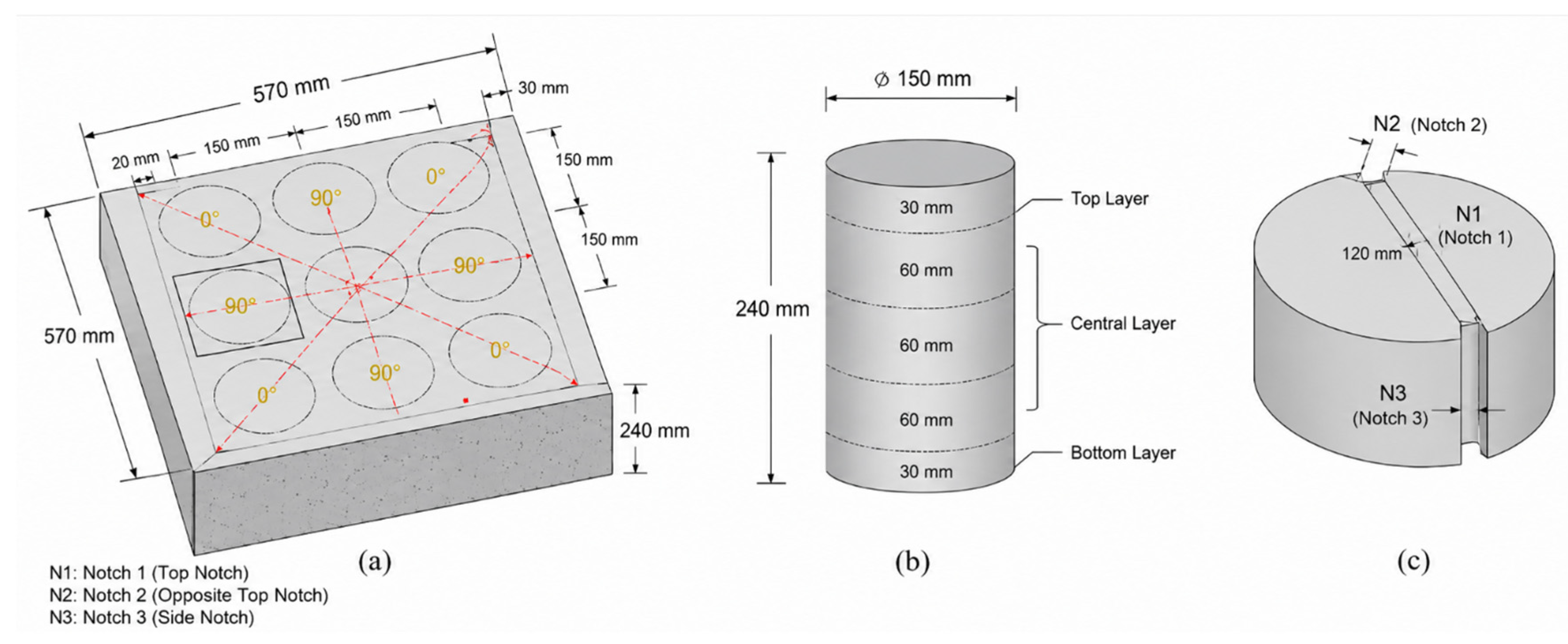
Panels measuring 570 × 570 × 240 m m were cast from the center so that the SFRSCC flowed radially toward the boundaries, Figure 1. Cylindrical cores were extracted along the flow paths and sectioned into 150 m m diameter × 60 m m thick disks. Opposing primary notches and auxiliary grooves were introduced to localize fracture. Two crack-plane orientations were considered: θ   =   0 ° , for which the notched plane was parallel to the concrete flow direction, and θ   =   90 ° , for which it was perpendicular to the flow direction, Figure 1.
Figure 1. Experimental benchmark used to construct the numerical geometry: (a) core extraction from the centrally cast panel; (b) subdivision of a cylindrical core through the panel depth; and (c) notched disk geometry. Adapted from Hosseinmostofi et al. [5].
Fibers 14 00109 g001
Splitting tests were carried out under displacement control using a testing system with a maximum load capacity of 1500 k N . Test control was achieved through an external displacement transducer mounted on the actuator. The imposed displacement rate was 1.0 µ m / s (0.001 m m / s ) up to an actuator displacement of 2.0 m m , increased to 2.0 µ m / s (0.002 m m / s ) from 2.0 to 3.0 m m , and subsequently to 4.0 µ m / s (0.004 m m / s ) until completion of the test. The first two loading stages required approximately 33.3 and 8.3 min, respectively, corresponding to approximately 41.7 min to reach an actuator displacement of 3.0 m m . Thereafter, the total test duration depended on the final displacement reached by each specimen. Crack opening was measured with five LVDTs distributed over the front and rear faces. The test was initially driven at 1.0 μ m / s , increased to 2.0 μ m / s after 2.0 m m actuator displacement, and to 4.0 μ m / s after 3.0 m m . The staged displacement-control protocol was adopted to maintain stable test control during crack initiation and the early stages of crack propagation. Accordingly, the lowest displacement rate of 1.0 µ m / s was maintained up to an actuator displacement of 2.0 m m . Once stable post-cracking propagation had been established, the rate was increased to 2.0 µ m / s from 2.0 to 3.0 m m and to 4.0 µ m / s thereafter until completion of the test. The same loading history was applied consistently to all specimens. Although the mechanical response of cementitious materials can be loading rate-dependent, rate effects were not investigated in the present experimental program; the measured responses should therefore be interpreted as corresponding to this common prescribed loading protocol. Table 2 presents the experimental quantities represented in the finite element model.
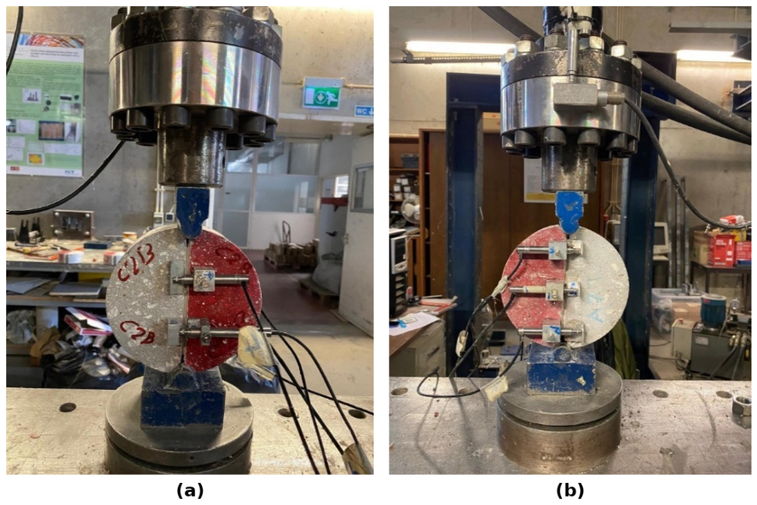
Figure 2 shows the physical test arrangement that was replicated numerically.
The nominal splitting tensile stress was evaluated using the effective load-transfer dimensions of the notched disk:
σ S P = 2 F π D L
where F is the applied load, D = 120 m m is the effective load transfer diameter after accounting for the two opposite notches, and L = 50 m m is the effective thickness across the notched section.
Table 2. Experimental quantities represented in the finite element model.
ItemValue Used for Numerical Reconstruction
Disk geometry 150   m m   diameter   ×   60   m m thickness
Primary notch 5   m m depth on opposing sides
Crack-plane orientations θ = 0 °   and   θ = 90 °
Loading modeDisplacement controlled
Crack-opening measurementFive LVDTs on front/rear faces
Material groupsFour ISF/RSF mixtures

2.3. Fiber Orientation Information Used for Interpretation

The earlier study measured fiber architecture independently of the finite element analysis. Digital image analysis showed that the number of effective fibers intersecting the fracture plane was higher for θ   =   0 ° than for θ   =   90 ° in every mixture. For C 90 I 0 R , C 45 I 45 R , C 30 I 60 R , and C 0 I 90 R , the effective fiber counts were 2.82, 3.90, 4.01, and 4.18 for θ   =   0 ° , compared with 1.78, 3.16, 3.39, and 3.47 for θ   =   90 ° , respectively. The corresponding orientation factors were also consistently higher for θ   =   0 ° . Micro-CT confirmed the casting-induced orientation trend and showed increasing orientation randomness as RSF content increased. These independent measurements are important when interpreting the orientation-conditioned constitutive response identified numerically.

2.4. Experimental Results Used for Constitutive Identification and Numerical Assessment

The complete experimental investigation, including material characterization, digital image analysis, and micro-computed-tomography assessment, was reported previously [5]. The principal mechanical results required for constitutive identification and numerical assessment are summarized here. The average splitting tensile stress-crack-opening responses show a pronounced influence of both RSF replacement and crack-plane orientation. The all-ISF reference mixture developed the highest peak tensile resistance. Replacing 50%, 67%, and 100% of the ISFs with RSFs reduced the peak splitting tensile stress by approximately 15%, 19%, and 34%, respectively. The post-peak response, however, did not decrease proportionally with peak strength: at a crack width of 1.0 m m , the reference specimens exhibited an approximately 30% stress reduction from the peak, whereas the corresponding reductions for 50%, 67%, and 100% RSF replacement were approximately 21%, 23%, and 17%, respectively. Thus, the hybrid and mono-RSF mixtures exhibited smoother post-peak decay and sustained crack-bridging action at larger crack openings.
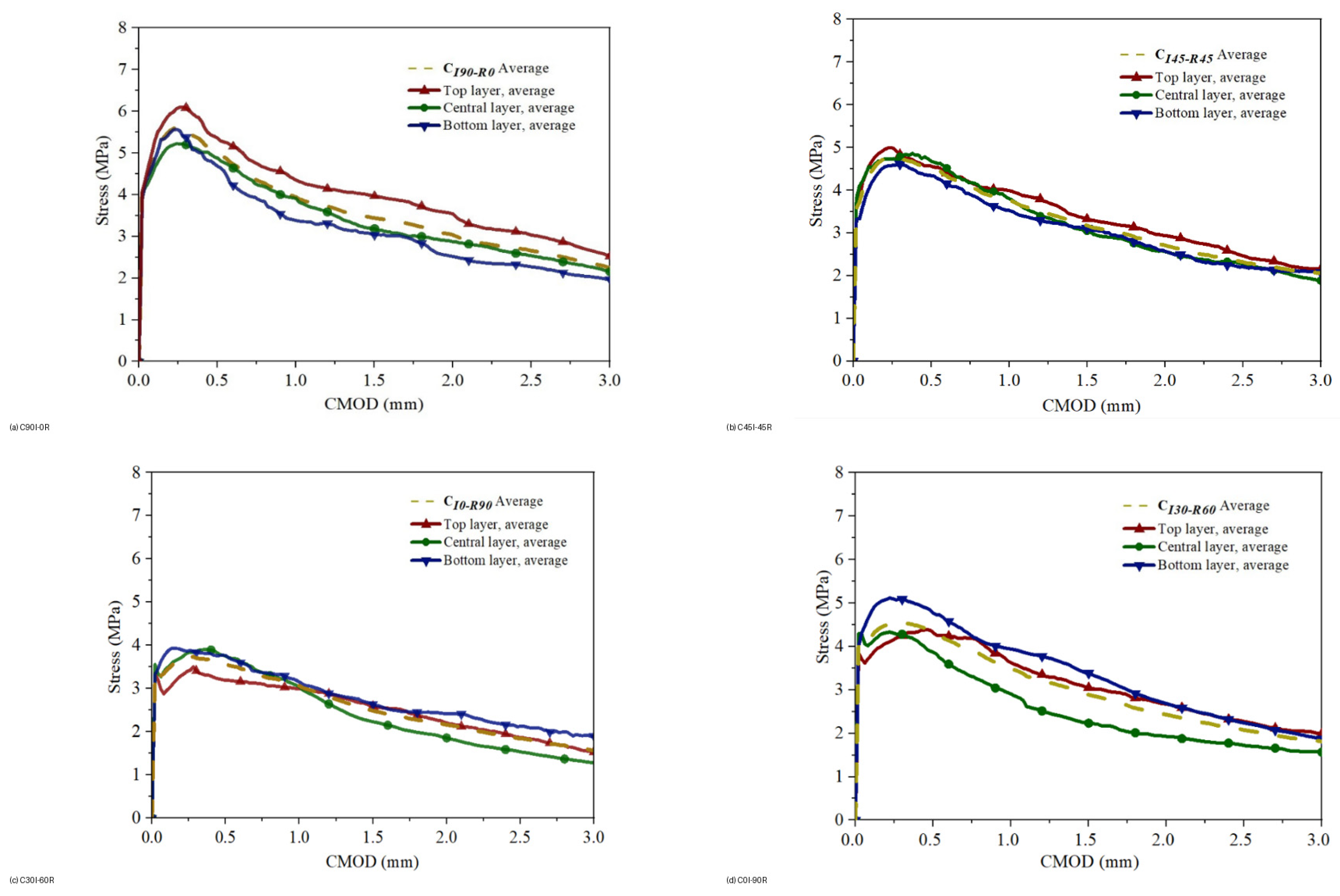
The directional effect was systematic. For every mixture, specimens with the crack plane parallel to the concrete flow direction ( θ   =   0 ° ) exhibited higher peak and residual tensile stresses than the corresponding θ   =   90 ° specimens. This response is consistent with the independently measured fiber architecture: the effective fiber population intersecting the fracture plane and the orientation factor were higher for θ   =   0 ° [5]. Differences among specimens extracted from the top, central, and bottom layers were comparatively small, indicating that significant fiber segregation through the panel depth did not occur. The experimental curves used for numerical comparison are shown in Figure 3, while Table 3 reports the average peak/residual stresses and fracture energy indices used to quantify the response.
The residual response followed the same overall trend as the peak strength, but the relative loss in post-cracking performance was less severe than the reduction in peak resistance. At a crack opening of 1.0 m m , replacing 50%, 67%, and 100% of the ISFs with RSFs reduced the average residual strength by approximately 4%, 11%, and 23%, respectively, while the corresponding reductions in absorbed energy were approximately 10%, 14%, and 28%. These results demonstrate that RSF replacement modifies the shape of the tensile softening response rather than simply scaling the peak strength; consequently, the complete post-cracking law and the casting-induced directional effect must be represented in the numerical formulation.

3. Finite Element Methodology

3.1. Geometry, Element Formulation, and Boundary Conditions

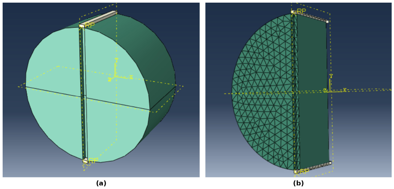
The three-dimensional model was developed in Abaqus/Standard (SIMULIA, Dassault Systèmes) [17]. Eight-node hexahedral solid elements with eight integration points were adopted, corresponding to the full-integration C3D8 formulation, Figure 4. The final mesh contained 5674 elements. The notched ligament was represented explicitly so that tensile-damage localization could develop along the experimentally prescribed fracture plane. Mesh refinement was concentrated in the ligament and around the notch tips, where the highest tensile damage gradients were expected, while a coarser discretization was retained away from the fracture zone to control computational cost. The post-cracking tensile response was defined through a displacement-based stress-crack-opening relation rather than a conventional strain-softening law, reducing the direct dependence of the dissipated fracture energy on characteristic element length. The adopted discretization was subsequently assessed through direct numerical–experimental comparison of the global stress-crack-opening response and the localized fracture pattern. Rigid loading plates were placed above and below the disk. The lower plate was restrained, while the upper plate was subjected to a prescribed vertical displacement. Normal contact was defined as hard contact, and tangential interaction at the loading plate–concrete interface was represented using Coulomb friction with μ f = 0.62 . This value was adopted as a representative steel–concrete contact coefficient based on experimentally reported values for rolled steel plate against cast-in-place concrete or grout, which range approximately from 0.57 to 0.70 [18]. The coefficient applies only to the loading plate–concrete interface and not to fiber–matrix interaction. Accordingly, its role is limited to local tangential slip and load transfer beneath the loading plates, whereas the post-cracking response in the notched ligament is represented through the orientation-conditioned tensile stress-crack-opening law. The displacement-controlled solution procedure was selected to follow the descending post-peak branch with improved numerical stability. Table 4 summarizes the principal finite element modeling choices.
Figure 4. Three-dimensional finite element model: (a) specimen geometry, loading, and constraints; and (b) C3D8 discretization with local refinement in the notched ligament.
Fibers 14 00109 g004
Table 4. Principal finite element modeling choices.
Numerical ItemAdopted Specification
SolverAbaqus/Standard, static nonlinear analysis
Concrete elementsC3D8; 8-node linear brick; full integration
Concrete element count5674
Elastic modulus, E0 30   G P a
Poisson ratio, ν0.20
LoadingPrescribed vertical displacement
Normal contactHard contact
Loading plate–concrete tangential contactCoulomb friction μ f = 0.62

3.2. Concrete Damage Plasticity Formulation

The homogenized SFRSCC was represented using the concrete damage plasticity (CDP) model. CDP combines a pressure-sensitive plasticity formulation with independent tensile and compressive damage variables and is widely used for quasi-brittle cementitious composites [13,14,15]. The adopted parameters were a dilation angle of 40°, a flow potential eccentricity of 0.10, a biaxial-to-uniaxial compressive strength ratio of 1.16, a tensile/compressive meridian ratio of 0.667, and a viscosity parameter of 0.01.Table 5 summarizes the concrete damage plasticity parameters adopted in the finite element model. The values ε   =   0.10 , f b 0 / f c 0   =   1.16 , and K c   =   0.667 correspond to the standard values of the Abaqus CDP formulation [17]. The dilation angle and viscosity parameter were adopted as fixed numerical parameters rather than being independently calibrated for each mixture; the small viscosity value was used for viscoplastic regularization in Abaqus/Standard during the nonlinear post-peak solution. The principal constitutive identification in this study concerns the experimentally derived orientation-conditioned tensile stress-crack-opening laws. Accordingly, all CDP plasticity parameters were maintained consistently for every mixture and orientation case to avoid case-specific adjustment and to isolate the influence of the directional tensile response.
Table 5. Concrete damage plasticity parameters.
ParameterSymbolValue
Dilation angleψ40°
Flow potential eccentricityε0.10
Equibiaxial/uniaxial compressive yield ratio f b 0 / f c 0 1.16
Deviatoric section shape factor K c 0.667
Viscosity parameterμ0.01
Compression was introduced into CDP as uniaxial stress versus inelastic strain. The experimental program reported an average compressive strength of approximately 60 MPa and an elastic modulus of approximately 30 GPa . Because the modified splitting test is governed primarily by tensile fracture in the notched ligament, the compressive response serves principally to represent the localized compression field beneath the loading strips. The inelastic compressive strain supplied to CDP is
ε c i n = ε c ε c e l = ε c σ c E 0
where ε c is the total compressive strain, ε c e l is the elastic compressive strain, σ c is the corresponding uniaxial compressive stress, and E 0 is the initial undamaged elastic modulus. This definition separates the irreversible compressive component required by CDP from the elastic contribution.

3.3. Orientation-Conditioned Tensile Softening

The steel fibers were not modeled individually. Their combined bridging contribution was incorporated through the tensile stress-crack-opening relation of the homogenized composite. A displacement-based formulation was selected because crack opening is the physically relevant variable for fiber pull-out and because it reduces the direct dependence of post-cracking energy dissipation on element length. The tensile law was represented by four descending linear segments defined by five points: the peak tensile stress at crack initiation, residual stress at crack openings of 0.3, 1.0, and 2.0 m m , and a terminal stress of zero at 4.0 m m . The first four coordinates were obtained from the measured splitting responses, while the 4.0 m m closure point was adopted as a numerical continuation to terminate the softening law beyond the principal 0–3 m m comparison interval.
The quadrilinear law was implemented by linear interpolation between consecutive experimental coordinates ( w i , σ i ). For each segment i, the tensile stress is
σ t ( w ) = σ i + σ i + 1 σ i w i + 1 w i ( w w i )
with w i w w i + 1 . The experimentally defined coordinates are w = 0, 0.3, 1.0, and 2.0 m m . A terminal point of σ t = 0 MPa at w = 4.0 m m is introduced only as a numerical continuation beyond the principal experimental comparison range, allowing the constitutive law to decay to zero without altering the measured coordinates used for constitutive identification and numerical comparison. Because the measured response is direction-dependent, a separate effective law was assigned to each mixture and notch orientation. This is an orientation-conditioned homogenization: the law represents the combined effect of matrix cracking, fiber pull-out, fiber count, and fiber alignment for the tested direction. It should therefore not be interpreted as an isotropic intrinsic material law. This treatment is consistent with the independent orientation measurements in [5] and with recent studies showing that fiber orientation changes the post-cracking tensile law [1,8,9]. Table 6 presents the experimental stress coordinates used to define the orientation-conditioned tensile softening laws.
Table 6. Experimental stress coordinates used to define the orientation-conditioned tensile softening laws. Each law is extended numerically to σ t = 0   M P a at w   =   4.0   m m .
Mixtureθ σ t , 0 σ 0.3 σ 1.0 σ 2.0
C 90 I 0 R 4.774.613.412.69
C 90 I 0 R 90°2.892.561.951.49
C 45 I 45 R 3.793.493.052.26
C 45 I 45 R 90°2.962.511.931.39
C 30 I 60 R 3.833.483.152.23
C 30 I 60 R 90°2.632.141.911.41
C 0 I 90 R 3.172.922.611.81
C 0 I 90 R 90°2.391.841.721.31
For compatibility with the CDP tensile formulation, the corresponding cracking-strain measure was calculated relative to the undamaged elastic response as
ε t c k = ε t ε t e l = ε t σ t E 0
where ε t is the total tensile strain, ε t e l is the elastic tensile strain, σ t is the current tensile stress, and E 0 is the initial undamaged elastic modulus.
For the tensile damage variable, a normalized scalar degradation variable was used to relate stiffness loss to the descending tensile branch:
d t = 1 σ t σ t 0
where σ t 0 is the peak tensile stress of the relevant mixture/orientation, and σ t is the current tensile stress on the softening branch. In Abaqus, tensile cracking strain was obtained by subtracting the elastic component from total tensile strain when strain-based entries were required.

3.4. Output Processing and Numerical–Experimental Comparison

The principal numerical outputs were the upper-plate reaction force, horizontal opening displacement across the notch, tensile damage, and stress distribution. Crack opening was extracted between numerical gauge points corresponding to the experimental LVDT locations. The model response was then compared directly with the experimental nominal tensile stress-crack-opening curves for all eight mixture/orientation combinations.
To reproduce the experimental deformation measure, the relative horizontal displacement between the two numerical gauge points was converted to an engineering strain according to
ε n u m = Δ u L 0
where Δ u is the relative horizontal displacement between the numerical gauge points, and L 0 is their initial separation. The same gauge locations used by the experimental LVDTs were reproduced in the finite element post-processing so that numerical and experimental responses were compared on an equivalent basis.
Numerical–experimental accuracy was quantified using the absolute relative difference in tensile stress at the characteristic response points, including the peak stress and the residual stresses at crack openings of 0.3, 1.0, and 2.0 mm. The relative error was calculated as
R e l a t i v e   e r r o r   ( % ) = σ n u m σ e x p σ e x p × 100
where σnum and σexp are the numerical and experimental tensile stresses, respectively. For the investigated mixture/orientation cases, the deviations at the evaluated characteristic response points remained below 5%.
The numerical tensile damage pattern was also examined to confirm localization through the notched ligament. Taken together, the global response and localized damage field provide complementary evidence for the adequacy of the orientation-conditioned homogenized CDP representation.

4. Numerical–Experimental Results

4.1. Crack Localization and Tensile Damage

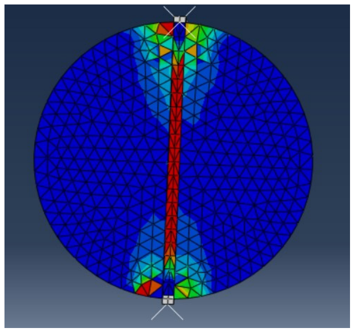
The CDP solution produced a localized tensile damage band connecting the two primary notches, Figure 5, reproducing the intended fracture path of the modified splitting test. The highest tensile damage developed first at the notch tips and then propagated through the central ligament as displacement increased. This localization confirms that the auxiliary groove system successfully suppresses uncontrolled cracking near the loading contacts and concentrates the fracture process in the region monitored experimentally.
Figure 5. Representative tensile damage localization obtained from the CDP model at an advanced loading stage.
Fibers 14 00109 g005

4.2. Crack Plane Parallel to Concrete Flow (θ = 0°)

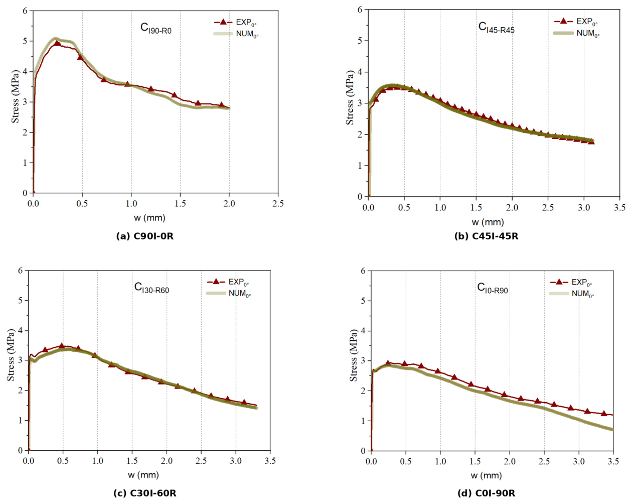
Figure 6 compares the measured and simulated responses for θ   =   0 ° . The numerical curves reproduce the abrupt transition from the predominantly elastic stage to a fiber-governed post-cracking branch and then follow the gradual decrease in residual stress. The all-ISF mixture develops the highest tensile capacity, whereas progressive RSF replacement reduces the peak resistance. Nevertheless, the RSF-containing mixtures preserve substantial residual stress over large crack openings, demonstrating that the irregular recycled fibers continue to bridge the fracture plane after matrix cracking.
The θ   =   0 ° configuration is the mechanically favorable orientation in the experimental program. This behavior is consistent with independent fiber count data: the fracture plane intersects a larger population of effectively oriented fibers when it is parallel to the concrete flow direction. The continuum model does not resolve the individual fibers; instead, this favorable architecture appears through the higher orientation-conditioned tensile softening parameters in Table 6.

4.3. Crack Plane Perpendicular to Concrete Flow (θ = 90°)

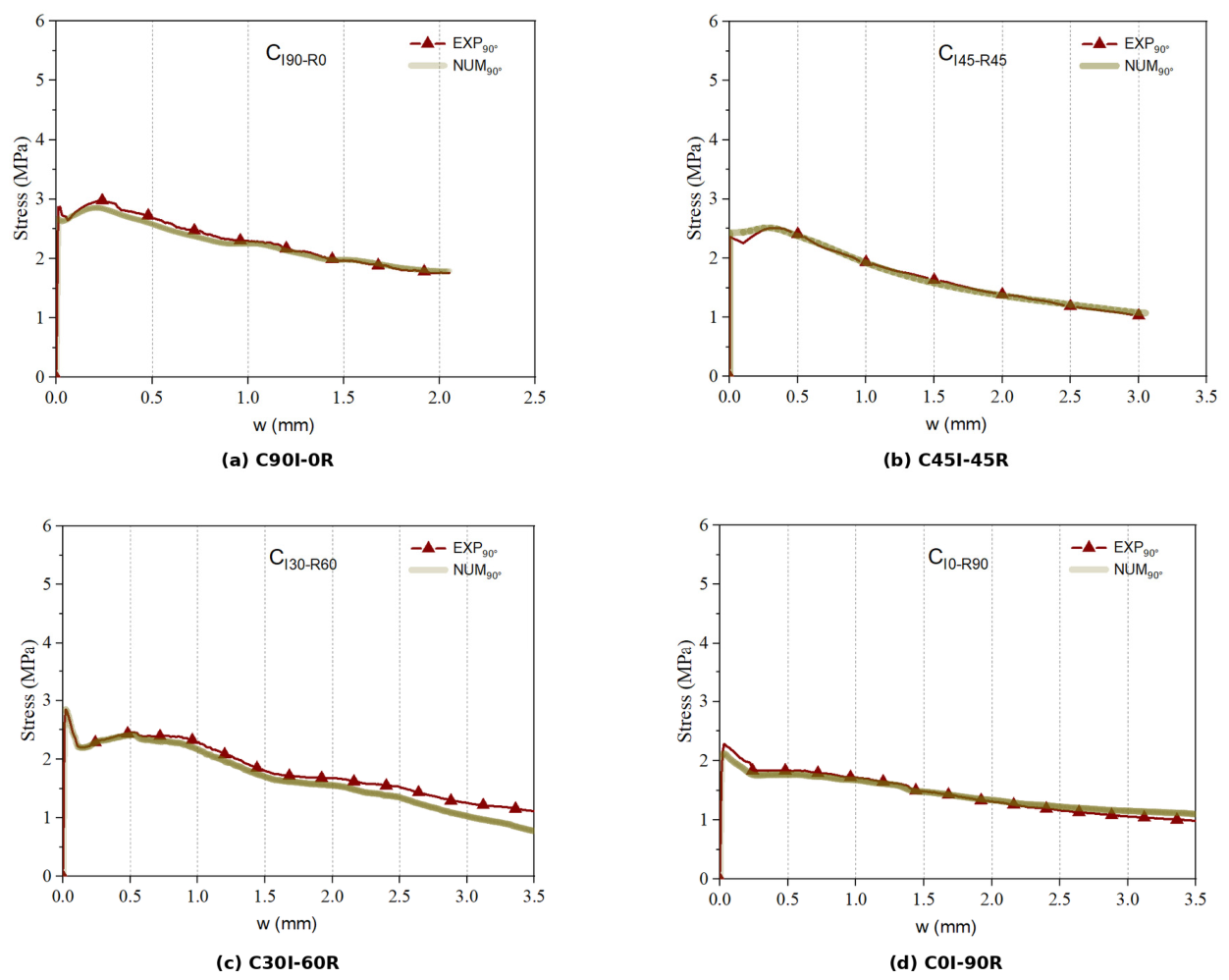
For θ = 90° (Figure 7), both peak and post-cracking stress are lower. The numerical model captures the reduced initial post-cracking resistance and the subsequent smooth decay for all four mixtures. The reduction is most pronounced for the reference C 90 I 0 R mixture, consistent with the larger difference in effective fiber count between its two orientations. In RSF-rich mixtures, the directional contrast remains clear but becomes less extreme because the irregular recycled fibers generate a broader orientation distribution.

4.4. Effect of Recycled Fiber Replacement

The reductions in tensile performance associated with progressive RSF replacement were established experimentally in the previous study [5] and are used here as the benchmark for the numerical reconstruction. The present numerical contribution is therefore not the re-identification of these experimental percentage reductions, but the ability of the orientation-conditioned CDP formulation to reconstruct the relative response of the four mixtures for both investigated crack plane orientations. As shown in Figure 6 and Figure 7, the numerical responses reproduce the progressive reduction in peak resistance with increasing RSF content and the corresponding evolution of the post-cracking response. Quantitative numerical–experimental agreement is assessed at the characteristic response points using the relative error measure defined in Section 3.4. Because the tensile constitutive laws were identified from the corresponding experimental peak and residual coordinates, these comparisons represent reconstruction accuracy within the calibrated experimental domain rather than an independent prediction of the previously reported reduction percentages.
Post-peak behavior provides a more nuanced result. Although the all-ISF concrete has the highest peak resistance, the RSF and hybrid mixtures exhibit comparatively smooth stress decay. The numerical softening branches reproduce this characteristic. The result suggests that replacing ISFs with RSFs does not simply scale the tensile curve downward; it changes the shape of the post-cracking constitutive response. This distinction is important when the material is used in analyses governed by crack width control, toughness, or redistribution rather than peak strength alone.

5. Discussion

5.1. Relationship Between Numerical Parameters and Fiber Orientation

A major outcome of the combined experimental and numerical evidence is that orientation should be treated as a constitutive variable in engineering-scale SFRSCC modeling. In the Buildings study [5], the θ   =   0 ° series exhibited consistently larger effective fiber counts and orientation factors. The numerical identification in the present work requires correspondingly higher residual tensile stresses for θ   =   0 ° . The two observations are physically consistent: a larger number of fibers crossing the crack at favorable inclinations increases the bridging force that must be represented by the homogenized tensile law. The magnitude of this directional effect can also be quantified from the characteristic tensile parameters in Table 3. Across the four mixtures, the peak tensile stresses measured for the θ   =   0 ° orientation were approximately 28–65% higher than those obtained for θ   =   90 ° . The directional contrast was even more pronounced in the post-cracking regime: at a crack opening of w   =   1.0   m m , the residual tensile stresses for θ   =   0 ° exceeded the corresponding θ   =   90 ° values by approximately 52–75%, depending on the mixture. These differences quantify the level of casting-induced anisotropy that must be represented by the orientation-conditioned tensile laws. They should be interpreted as quantitative characteristics of the experimental benchmark used for constitutive identification, while the numerical model evaluates how effectively this directional response can be reconstructed within the homogenized CDP framework.
This interpretation is supported by recent direct tensile work in which changes in manufacturing-induced fiber orientation produced significant differences in tensile stress at small crack openings [1] and by full-scale casting studies demonstrating that rheology and placement affect fiber architecture [8]. Thus, a single isotropic tensile softening curve is unlikely to be transferable between locations or loading directions when casting creates a preferential fiber field.

5.2. Appropriate Role of a Homogenized CDP Model

The proposed formulation is intended for engineering-scale analysis. Its principal advantage is computational efficiency: the crack-bridging contribution of the fiber population is represented through the calibrated tensile law, avoiding explicit discretization of thousands of individual fibers. The close reproduction of the measured splitting test curves indicates that CDP combined with orientation-conditioned stress-crack-opening laws can represent the global response of the investigated SFRSCC mixtures while retaining a conventional continuum finite element framework.
The principal limitation of the homogenized formulation is that fiber architecture is represented implicitly through the direction-specific tensile law rather than through discrete fibers. The calibrated constitutive laws are therefore most directly applicable to material, casting, and orientation conditions comparable to those investigated experimentally. For substantially different casting configurations or fiber distributions, independent orientation characterization or casting process simulation should be used to establish the relevant directional tensile response. Within this scope, the continuum approach provides a practical balance between physical interpretation and computational efficiency for structural-scale finite element analysis. The present formulation should not be interpreted as a predictive model for arbitrary fiber contents. All mixtures investigated herein contained a constant total steel fiber dosage of 90 kg/m3, while only the ISF/RSF proportion was varied. Accordingly, the tensile laws were identified for these specific mixtures and fiber dosage. Extension of the framework to lower or higher fiber contents would require corresponding experimental stress-crack-opening data so that fiber dosage could be introduced explicitly as a constitutive variable.
The adopted stress-crack-opening formulation is also closely related to nonlinear fracture mechanics, since the post-cracking law may be interpreted as an effective traction–separation relation governing fracture-process-zone dissipation. More explicit approaches, such as cohesive crack, cohesive zone, or XFEM formulations, could alternatively be used to model crack initiation and propagation. The present CDP formulation was retained to combine the experimentally measured fracture response with a computationally efficient continuum framework. Because each orientation-conditioned tensile law was identified from the experimental response of the corresponding mixture/orientation case, the present comparisons quantify reconstruction accuracy within the calibrated experimental domain rather than independent predictive accuracy for unseen material states. Transfer of the identified parameters should therefore be limited to comparable material, fiber dosage, casting, and orientation conditions. Predictive use for new casting configurations or total fiber dosages requires independently determined orientation information and/or constitutive data for those conditions. Independent validation against additional, non-calibration datasets remains an important step for future development of the framework. Although the displacement-based softening formulation and local refinement of the fracture zone reduce the direct mesh sensitivity of the post-cracking response, a formal three-level mesh convergence study was not conducted. Quantification of mesh objectivity across different discretization levels and structural scales therefore remains a subject for further investigation. A systematic sensitivity analysis of the CDP dilation angle and viscosity parameter was not undertaken; these parameters were maintained consistently across all simulations, and their influence on model transferability should be examined in future studies.

5.3. Implications for Recycled Steel Fiber Concrete

The combined experimental and numerical results have two direct implications for the structural use of recycled steel fibers. First, RSF performance should not be judged from peak tensile strength alone: the hybrid and mono-RSF mixtures retain meaningful residual stress at service-relevant crack openings despite lower peak resistance. Second, casting-induced orientation can alter the effective crack-bridging capacity at a fixed nominal fiber dosage. Consequently, constitutive laws used in structural analysis should reflect the relevant fiber orientation whenever preferential alignment is expected. The orientation-conditioned framework developed here provides a practical route for introducing this effect without explicit fiber modeling. The ISF reference used in this study already consisted of purpose-manufactured hooked-end steel fibers. Future work could extend the comparison to other engineered fiber geometries, such as ribbed, crimped, twisted, or multiple hook fibers, to quantify the influence of enhanced mechanical anchorage on pull-out resistance and post-cracking performance.

6. Conclusions

A three-dimensional orientation-conditioned CDP framework was developed and assessed against the measured splitting tensile response of self-compacting concrete reinforced with industrial and recycled tire steel fibers. The previously established experimental database provides the mechanical and fiber orientation basis, while the present study focuses on constitutive formulation, numerical reconstruction, and interpretation. The main conclusions are:
The C3D8 continuum model with displacement-controlled loading and explicit notch geometry reproduced the localized fracture mechanism and the overall stress-crack-opening response of the modified splitting test.
Orientation-conditioned quadrilinear tensile laws provided an efficient means of representing the combined effects of fiber pull-out, fiber count, and fiber alignment within a homogenized CDP framework. Numerical–experimental deviations remained below 5% at the evaluated characteristic response points.
The experimental benchmark previously reported in [5] showed peak strength reductions of approximately 15%, 19%, and 34% for 50%, 67%, and 100% RSF replacement, respectively; the present numerical framework successfully reconstructed the corresponding progressive response.
Despite the lower peak resistance, hybrid and mono-RSF mixtures retained a gradual post-cracking response, indicating that recycled fibers continued to transfer tensile stress across relatively large crack openings.
The θ   =   0 °  series consistently exhibited greater residual capacity than θ   =   90 ° . This numerical trend is consistent with the independent digital image and micro-CT measurements reported in [5], which showed a larger population of effectively oriented fibers for θ   =   0 ° .
The proposed model is suitable for efficient engineering-scale reconstruction and structural analysis when the relevant tensile law is known. Predictive transfer to new casting configurations should incorporate measured or simulated fiber orientation fields rather than assuming isotropic behavior.
The principal limitation of the present framework is its calibration dependence: the orientation-conditioned tensile laws were identified from the corresponding experimental responses, and all investigated mixtures contained a constant total steel fiber dosage of 90 kg/m3. The model should therefore be regarded as a reconstruction framework for comparable material, casting, and orientation conditions rather than as an independently predictive model for arbitrary fiber contents or configurations. Future work should include validation against independent non-calibration datasets, extension to additional fiber dosages and casting conditions, and systematic assessment of mesh objectivity and sensitivity to the principal CDP numerical parameters.

Author Contributions

K.H.: conceptualization, investigation, methodology, software, and writing—original draft. F.S.: investigation, formal analysis, validation, and visualization. E.N.B.P.: investigation, formal analysis, validation, visualization, and supervision. All authors have read and agreed to the published version of the manuscript.

Funding

This research is part of the first author’s PhD project, “Advanced prefabricated multifunctional floating dock system for offshore renewables” (reference 2020.09697), supported by Fundação para a Ciência e a Tecnologia (FCT).

Data Availability Statement

The original contributions presented in this study are included in the article. Further inquiries can be directed to the corresponding author.

Conflicts of Interest

Author Fatemeh Soltanzadeh was employed by the company DIS/CREADIS. The remaining authors declare that the research was conducted in the absence of any commercial or financial relationships that could be construed as a potential conflict of interest.

References

  1. Faustmann, S.; Kronau, M.; Fischer, O. Direct tensile tests on steel fiber reinforced concrete with focus on wall effect and fiber orientation. Mater. Struct. 2024, 57, 185. [Google Scholar] [CrossRef] [Scilit]
  2. Wang, Z.; Liang, X.; Wan, S.; Cao, Z.; Weng, S.; Wu, K. Experimental and theoretical investigation on axial tensile behavior of ultra-high performance concrete (UHPC) with recycled steel fibers from waste tires. Constr. Build. Mater. 2024, 456, 139300. [Google Scholar] [CrossRef] [Scilit]
  3. Romero, A.J.; Moustafa, M.A. Effect of recycled tires steel fibers characteristics on crack behavior and mechanical properties of scalable ultra-economical UHPC. J. Build. Eng. 2025, 99, 111582. [Google Scholar] [CrossRef] [Scilit]
  4. Zia, A.; Holly, I.; Zhang, P. Constitutive modeling and extended performance evaluation of concrete reinforced with non-hybrid waste tire steel fibers. J. Build. Eng. 2024, 96, 110522. [Google Scholar] [CrossRef] [Scilit]
  5. Hosseinmostofi, K.; Soltanzadeh, F.; Pereira, E.N.B. Differences in Distribution and Orientation of Industrial and Recycled Steel Fibers on Fiber-Reinforced Self-Compacting Concrete Using Computed Tomography. Buildings 2026, 16, 1841. [Google Scholar] [CrossRef] [Scilit]

  6. Frazão, C.; Barros, J.; Bogas, J.A.; García-Cortés, V.; Valente, T. Technical and environmental potentialities of recycled steel fiber reinforced concrete for structural applications. J. Build. Eng. 2022, 45, 103579. [Google Scholar] [CrossRef] [Scilit]
  7. Xiao, Z.; Pramanik, A.; Basak, A.K.; Prakash, C.; Shankar, S. Material recovery and recycling of waste tyres—A review. Clean. Mater. 2022, 5, 100115. [Google Scholar] [CrossRef] [Scilit]
  8. Abedi, M.; Rojas, G.; Domingo, M.; Martius-Hammer, T.A.; Kanstad, T.; Ji, G. Steel fiber distribution and orientation in full-scale walls cast from FRC with various consistencies and casting procedures: Evaluation by the inductive method. Mater. Struct. 2025, 58, 81. [Google Scholar] [CrossRef] [Scilit]
  9. González, D.C.; Mena-Alonso, Á.; Mínguez, J.; Martínez, J.A.; Vicente, M.A. Effect of Fiber Orientation on the Fatigue Behavior of Steel Fiber-Reinforced Concrete Specimens by Performing Wedge Splitting Tests and Computed Tomography Scanning. Int. J. Concr. Struct. Mater. 2024, 18, 4. [Google Scholar] [CrossRef] [Scilit]
  10. Zhao, Y.; Bi, J.; Wang, Z.; Huo, L.; Guan, J.; Zhao, Y.; Sun, Y. Numerical simulation of the casting process of steel fiber reinforced self-compacting concrete: Influence of material and casting parameters on fiber orientation and distribution. Constr. Build. Mater. 2021, 312, 125337. [Google Scholar] [CrossRef] [Scilit]
  11. Raju, R.A.; Lim, S.; Akiyama, M.; Kageyama, T. Effects of concrete flow on the distribution and orientation of fibers and flexural behavior of steel fiber-reinforced self-compacting concrete beams. Constr. Build. Mater. 2020, 262, 119963. [Google Scholar] [CrossRef] [Scilit]
  12. Zhou, W.-D.; Zhang, D.-M.; Zhang, X.; Huang, Z.-K.; Xie, X.-C. Experimental and mesoscale numerical investigation on tensile properties of steel fibre-reinforced concrete. Constr. Build. Mater. 2025, 458, 139601. [Google Scholar] [CrossRef] [Scilit]
  13. Lubliner, J.; Oliver, J.; Oller, S.; Oñate, E. A plastic-damage model for concrete. Int. J. Solids Struct. 1989, 25, 299–326. [Google Scholar] [CrossRef] [Scilit]
  14. Lee, J.; Fenves, G.L. Plastic-Damage Model for Cyclic Loading of Concrete Structures. J. Eng. Mech. 1998, 124, 892–900. [Google Scholar] [CrossRef] [Scilit]
  15. Faustmann, S.; Wolf, A.; Fischer, O. Development of an enhanced damage law for typical steel fiber reinforced concrete based on uniaxial compression and tension tests. Mater. Struct. 2024, 57, 150. [Google Scholar] [CrossRef] [Scilit]
  16. Soltanzadeh, F.; Behbahani, A.E.; Hosseinmostofi, K.; Teixeira, C.A. Assessment of the Sustainability of Fibre-Reinforced Concrete by Considering Both Environmental and Mechanical Properties. Sustainability 2022, 14, 6347. [Google Scholar] [CrossRef] [Scilit]
  17. Smith, M. ABAQUS/Standard User’s Manual, version 6.9; Dassault Systèmes Simulia Corp.: Providence, RI, USA, 2009. [Google Scholar]
  18. Rabbat, B.G.; Russell, H.G. Friction Coefficient of Steel on Concrete or Grout. J. Struct. Eng. 1985, 111, 505–515. [Google Scholar] [CrossRef] [Scilit]
Figure 2. Experimental notched splitting tensile test: (a) front-face instrumentation and (b) rear-face instrumentation.
Fibers 14 00109 g002
Figure 3. Experimental splitting tensile stress-crack-opening responses used for constitutive identification and numerical assessment: (a) C 90 I 0 R ; (b) C 45 I 45 R ; (c) C 30 I 60 R ; and (d) C 0 I 90 R . The curves show the overall average together with the responses obtained from the top, central, and bottom panel layers.
Fibers 14 00109 g003
Figure 6. Numerical–experimental comparison for θ   =   0 ° : (a) C 90 I 0 R ; (b) C 45 I 45 R ; (c) C 30 I 60 R ; and (d) C 0 I 90 R .
Fibers 14 00109 g006
Figure 7. Numerical–experimental comparison for θ = 90°: (a) C 90 I 0 R ; (b) C 45 I 45 R ; (c) C 30 I 60 R ; and (d) C 0 I 90 R .
Fibers 14 00109 g007
Table 1. Fiber contents of the SFRSCC mixtures.
MixtureISF (kg/m3)RSF (kg/m3)RSF Fraction of Total Fiber
C 90 I 0 R 9000%
C 45 I 45 R 454550%
C 30 I 60 R 306067%
C 0 I 90 R 090100%
Table 3. Average experimental splitting tensile parameters used for constitutive identification and numerical assessment. σ p e a k is the peak tensile stress; σ 0.3 , σ 1.0 , and σ 2.0 are residual stresses at crack openings of 0.3, 1.0, and 2.0 m m , respectively; and G F 1 and G F 2 are the fracture energy/toughness parameters reported in the experimental study [5].
Mixtureθ σ p e a k (MPa) σ 0.3 σ 1.0 σ 2.0 G F 1 G F 2
C 90 I 0 R 4.774.613.412.694.037.04
C 90 I 0 R 90°2.892.561.951.492.313.99
C 45 I 45 R 3.793.493.052.263.325.95
C 45 I 45 R 90°2.962.511.931.392.323.93
C 30 I 60 R 3.833.483.152.233.365.94
C 30 I 60 R 90°2.632.141.911.412.284.05
C 0 I 90 R 3.172.922.611.812.814.99
C 0 I 90 R 90°2.391.841.721.312.033.79
Disclaimer/Publisher’s Note: The statements, opinions and data contained in all publications are solely those of the individual author(s) and contributor(s) and not of MDPI and/or the editor(s). MDPI and/or the editor(s) disclaim responsibility for any injury to people or property resulting from any ideas, methods, instructions or products referred to in the content.