Article

Flexural Behavior of R-UHTCC and Recycled Concrete Composite Beams Reinforced with Steel Bars

1
School of Water Conservancy and Transportation, Zhengzhou University, Zhengzhou 450001, China
2
School of Civil Engineering, Henan University of Engineering, Zhengzhou 451191, China
*
Author to whom correspondence should be addressed.
Fibers 2025, 13(8), 110; https://doi.org/10.3390/fib13080110
Submission received: 23 June 2025 / Revised: 1 August 2025 / Accepted: 13 August 2025 / Published: 18 August 2025

Abstract

To promote the application of recycled concrete in construction engineering, the flexural behavior of ultra-high toughness cement-based composite (UHTCC) materials and recycled concrete composite beams was investigated in this study. Recycled aggregates were used in the production of both recycled UHTCC (R-UHTCC) and recycled concrete. A total of 10 beams were manufactured and tested under four-point bending load. The primary design parameters included concrete strength grade, R-UHTCC layer height, stirrup spacing in the pure bending section, and tensile reinforcement ratio. The effects of these parameters on the failure mode, crack width, load-midspan deflection response, ductility, load-tensile reinforcement strain response, and flexural capacity of the beams are discussed. The results indicate that limiting the use of R-UHTCC to a specific height range within the tensile zone of the beams can yield superior flexural properties compared to using R-UHTCC across the full section. The R-UHTCC and recycled concrete composite beams demonstrated good crack resistance, load-deflection response, and ductility. Compared to the R-UHTCC layer height and stirrup spacing, the influences of concrete strength and tensile reinforcement ratio on the flexural behavior of the composite beams are more significant. The maximum increase in flexural capacity and ductility index was 18.8% and 67.3%, respectively, as the concrete strength grade increased from C30 to C70. The flexural capacity increased by 64.6% as the longitudinal reinforcement ratio increased from 0.258% to 3.68%. Furthermore, a stiffness calculation method based on the effective moment of inertia was proposed and validated through experimental results. The research findings provide a theoretical and design basis for the application of R-UHTCC and recycled concrete composite beams in engineering.

1. Introduction

Due to the advantages of low cost, ease of formwork, and durability, reinforced concrete (RC) structures have become the most widely used type of building construction in the world. Many older buildings are nearing the end of their lifespan and are being demolished for redevelopment, leading to the generation of a large amount of construction waste [1,2]. Crushing construction waste into recycled aggregates for use in new buildings promotes sustainable development in the construction industry, which is an active area of research. However, recycled aggregates have several disadvantages, including high water absorption, high porosity, and the presence of weak interface transition zones [3,4,5], which result in inferior mechanical properties and durability of recycled aggregate concrete compared to natural aggregate concrete, thus limiting its use in load-bearing structures [6,7]. Existing research shows that the mechanical properties of recycled concrete with a 25% substitution of recycled aggregates result in a 10% reduction in strength, and higher dosages can lead to losses of up to 40% [8]. Compared to normal concrete beams, the flexural capacity of recycled concrete beams decreases by 8.8–26.5% as the recycled aggregate replacement rate increases [9]. As a result, enhancing the properties of recycled concrete is essential to promote its broader application.
Numerous studies [10,11,12] have demonstrated that adding fibers to concrete is an effective method for improving the mechanical properties of recycled concrete structures. Randomly distributed fibers can inhibit crack propagation and mitigate defects in recycled concrete caused by weak interface transition zones [13,14]. The test results conducted by Gao [15] showed that the fully recycled aggregate concrete beams reinforced with 1.0% volume fraction of steel fiber exhibited greater flexural capacity than natural aggregate concrete beams. The inclusion of steel fibers significantly improved the crack patterns and load-deflection response of the recycled concrete beams. Wang et al. [16] studied the flexural properties of recycled concrete beams incorporating modified basalt fiber and nano-silica. Their results indicated that both the cracking load, peak load, and ductility of the recycled concrete beams were significantly improved by adding modified basalt fiber and nano-silica, either separately or in combination. Ghosn’s research [17] indicated that the recycled concrete beams with a 0.75% hemp fiber volume fraction and 50% recycled coarse aggregate replacement exhibited comparable ultimate capacity to that of natural aggregate concrete beams with no fibers. Similar findings have also been reported regarding the improvement in the shear performance of recycled concrete beams through fiber addition [18,19,20]. Overall, these studies indicate that fibers can notably improve the mechanical properties of recycled concrete beams. However, the high cost of fibers, such as steel, basalt, and polypropylene fibers, presents a challenge. To reduce construction costs, researchers have proposed using a partial fiber-reinforced approach to improve beam performance.
Beams subjected to bending loads often experience cracking in the tensile zone, which not only compromises their mechanical properties but also creates pathways for the ingress of harmful substances such as chloride ions and sulfate. This leads to steel corrosion, spalling of the cover layer, and other durability issues. To mitigate these effects, incorporating fibers into the tensile zone of a beam is an effective strategy for enhancing both its mechanical and durability performance. Engineered cementitious composites (ECC), which are produced by adding polyvinyl alcohol or polyethylene fibers to a cement-based matrix, are characterized by ultra-high tensile strength [21], toughness [22], ultimate tensile strain [23], and the ability to undergo multiple cracking without failure [24]. Partially replacing the natural aggregate concrete with ECC in the tensile zones of the beams creates an ECC-RC composite structure that effectively leverages ECC’s superior properties while ensuring cost efficiency.
The ECC-RC composite beams demonstrated superior crack resistance alongside enhanced ductility performance [25,26]. Under the serviceability state, the crack width in the ECC layer remained below 0.05 mm, effectively protecting the reinforcing steel from corrosion [27,28,29]. Within a specific height range, the bearing capacity of the beams increased as the height of the ECC layer grew [26,30,31,32,33]. Increasing the thickness of the ECC layer typically enhances the bearing capacity of composite beams by approximately 10% to 40% [34]. Furthermore, ECC in the tensile zone mitigated typical failure modes, such as cover spalling and bond splitting, in RC beams during seismic events [35]. Yousef et al. [36] studied the flexural performance of functionally graded RC beams, where the normal-strength concrete in the beam was partially replaced by ultra-high-performance fiber-reinforced concrete in the compression or tension regions. The results showed that the flexural performance of the functionally graded RC beams was comparable to that of full-section ultra-high-performance fiber-reinforced concrete beams, while significantly reducing costs. Numerous studies have focused on determining the optimal height of the ECC layer and its impact on the stiffness, bearing capacity, and durability of ECC-RC composite beams. Overall, these beams exhibited excellent mechanical properties, durability, and cost-effectiveness. It is anticipated that incorporating ECC into the tensile zone of recycled concrete beams will also yield favorable results. However, research on the flexural behavior of recycled concrete beams partially replaced by ECC has been rarely reported. The effects of the ECC layer on the flexural behaviors—such as cracking, stiffness, ductility, and load capacity—of recycled concrete beams remain inadequately understood. Further experimental and theoretical studies on the flexural performance of ECC and recycled concrete composite beams are urgently needed. Furthermore, to reduce cement consumption and save natural resources, some scholars have proposed using industrial waste materials, such as crumb rubber, stone processing waste, or waste quarry dust, to produce eco-friendly ECC [37,38,39]. The results showed that the eco-friendly ECC could potentially reduce environmental impacts, including costs, energy consumption, and carbon emissions. Carbon emissions can be reduced by up to 36.22%, and material costs can be reduced by up to 30.57% [40], thereby enhancing the sustainability of ECC while maintaining or improving its performance.
Based on the above research, it can be concluded that ECC-RC composite beams improve beam performance while simultaneously reducing project costs. Both normal concrete and ECC can use recycled aggregates to replace natural aggregates, thereby enhancing their sustainability. The use of fully recycled aggregates in composite beams holds significant ecological and economic value. However, there is currently no research on the flexural behavior of ECC-RC composite beams with fully recycled aggregates. Against this background, in this study, 10 composite beams made from ultra-high toughness cement-based composite (UHTCC) materials and recycled concrete were tested under bending load. The UHTCC made entirely from recycled fine aggregate (R-UHTCC), previously developed by the author team [41], was used in this program. The effects of concrete strength, R-UHTCC layer height, stirrup spacing in the constant moment region, and reinforcement ratio on the flexural performance of the R-UHTCC and composite beams—including failure mode, crack patterns, midspan deflection, stiffness, ductility, and load capacity—are analyzed. Additionally, a stiffness calculation method for the R-UHTCC and recycled concrete composite beams is proposed and validated experimentally. The highlight of this paper lies in the use of fully recycled aggregates in both concrete and UHTCC. The cooperative performance of R-UHTCC and recycled concrete was explored, and the suitable thickness of the R-UHTCC layer for composite beams was proposed. The research findings lay a foundation for the application of fully recycled aggregate concrete in engineering.

2. Experimental Program

2.1. Materials

Portland cement was used to produce the recycled concrete and R-UHTCC, and its 28-day compressive strength was 42.5 MPa. The discarded concrete specimens from testing stations, with cube compressive strengths of 30–60 MPa, were used to crush the recycled aggregates. The aggregates used in both recycled concrete and R-UHTCC in this experiment were entirely recycled aggregates. The waste specimens were initially crushed using a jaw crusher to obtain coarse aggregates, followed by further crushing to produce finer aggregates. The aggregates were then sieved through various screens to classify them into three sizes: 5–20 mm, 0–5 mm, and 0–1.18 mm. The 0–5 mm and 5–20 mm aggregates were used as recycled fine and coarse aggregates for the recycled concrete, while the 0–1.18 mm aggregates were used to produce the R-UHTCC. Figure 1 presents the gradation curves of the aggregates, and Table 1 lists the physical and mechanical properties of the recycled aggregates.
The first-grade fly ash, which meets the Chinese standard [42], was used as a cementitious material to enhance the performance of R-UHTCC. A water reducer with a water-reducing rate of 25% was used in this study. Table 2 lists the properties of polyvinyl alcohol fiber used for R-UHTCC. Four types of hot-ribbed steel bars, including HRB400 and HRB500 with nominal yield strengths of 400 MPa and 500 MPa, respectively, were used in the composite beams. Table 3 lists the physical and mechanical properties of the steel bars.

2.2. Mix Proportion Design

The target compressive strengths of the recycled concrete were designed to be C30, C50, and C70, respectively. Table 4 lists the detailed mix proportions of the recycled concrete.
Similarly, the compressive strengths of R-UHTCC were also designed to be C30, C50, and C70, respectively. The mixed proportions of the R-UHTCC in the composite beam refer to previously published literature by the author team [41], which reports an ultimate tensile strength exceeding 2.5 MPa and an ultimate tensile strain exceeding 3%. Table 5 lists the detailed mix proportions of R-UHTCC.

2.3. Specimen Design and Reinforcement

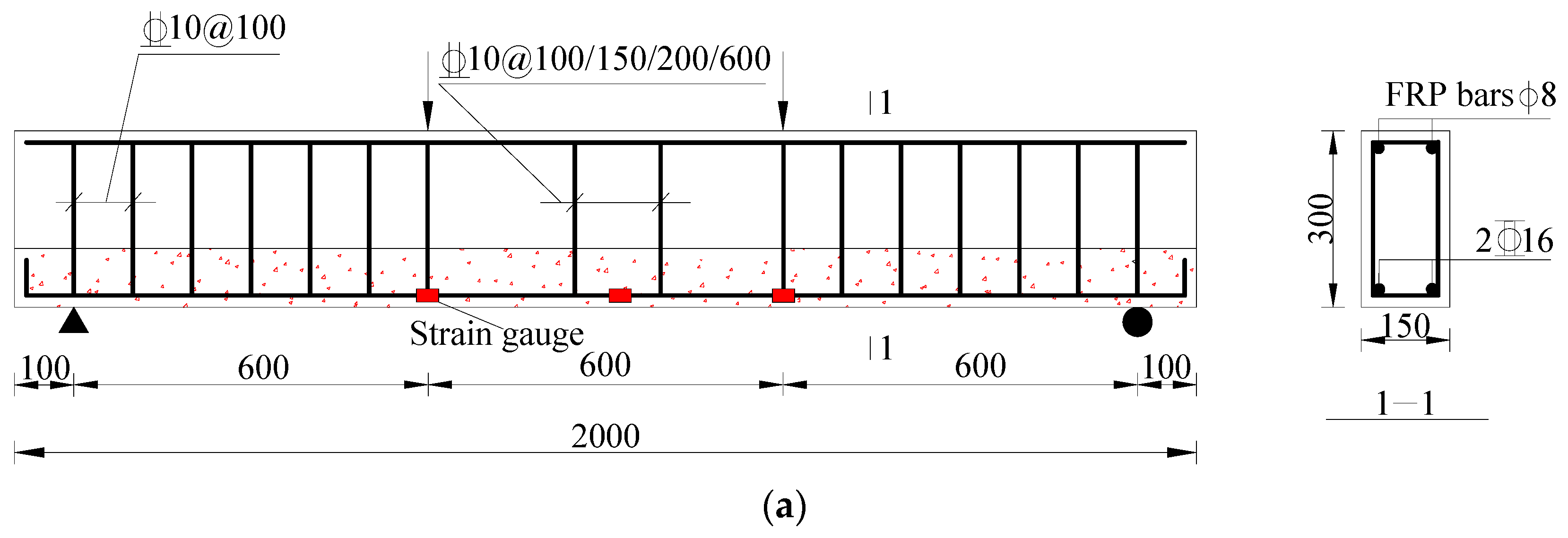
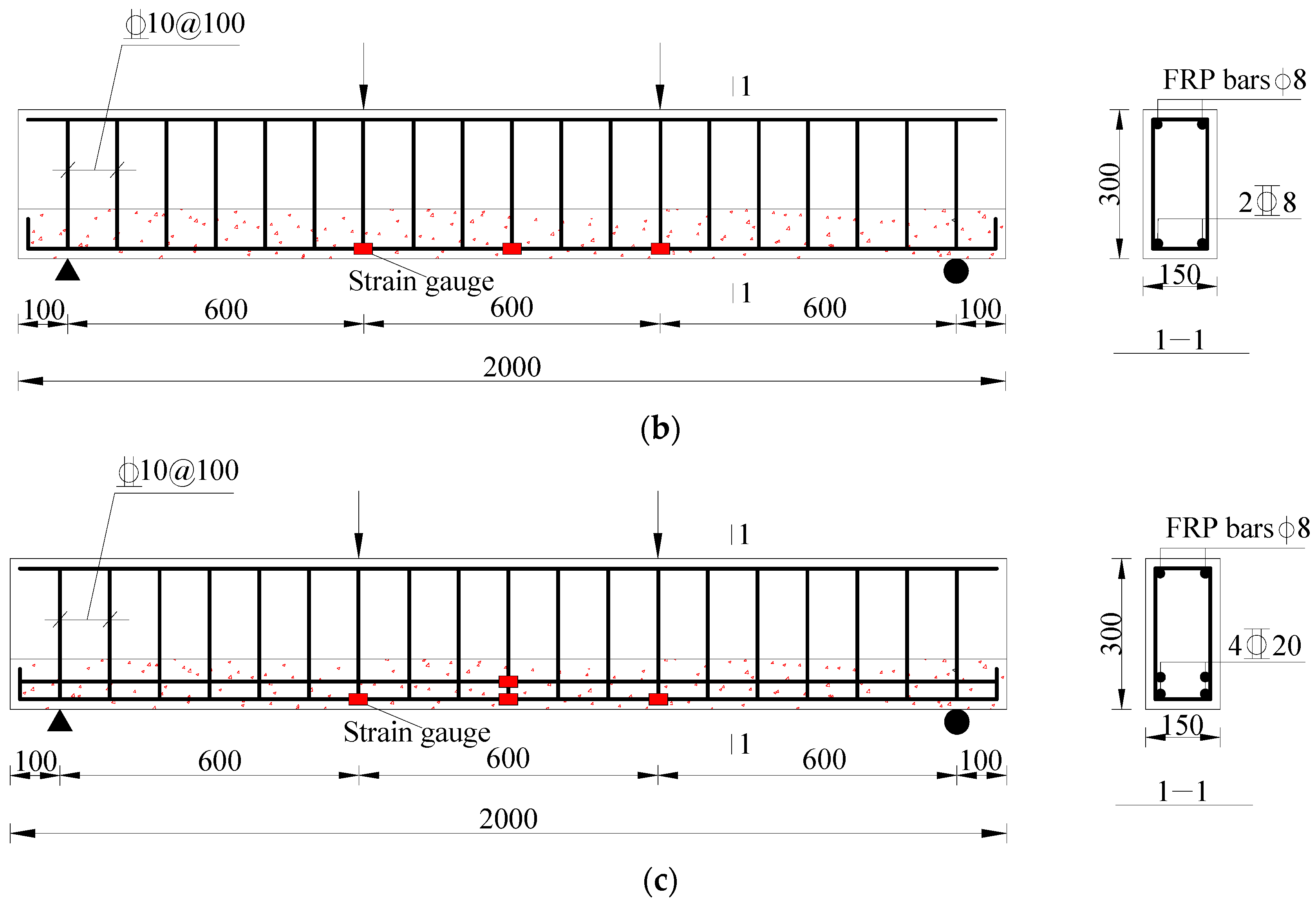
A total of 10 beams were designed in this study. All beams had a length of 2000 mm and a cross-sectional dimension of 150 mm × 300 mm. The key design parameters included concrete strength grade, R-UHTCC layer height, stirrup spacing in the constant moment region, and reinforcement ratio. The concrete strength grades were specified as C30, C50, and C70. The recycled concrete and R-UHTCC in each composite beam shared the same strength grade. The R-UHTCC layer heights were set at 100 mm, 200 mm, and 300 mm. The stirrup spacings were designed as 100 mm, 150 mm, 200 mm, and no stirrups, respectively. The reinforcement ratios were 0.258%, 1.043%, and 3.681%, corresponding to rare, balanced, and over-reinforcement, respectively. Table 6 presents the detailed design parameters for each beam. The beam identifier is a combination of letters and numbers: the uppercase ‘C’ denotes concrete strength, followed by the strength grade number; ‘H’ represents the R-UHTCC layer height, with ‘1’ indicating 100 mm, ‘2’ for 200 mm, and ‘3’ for 300 mm; ‘S’ denotes stirrup spacing, with ‘10’ for 100 mm, ‘15’ for 150 mm, ‘20’ for 200 mm, and ‘60’ indicating no stirrups in the pure bending section; ‘R’ indicates reinforcement ratio, with ‘0’ for 0.258%, ‘1’ for 1.043%, and ‘3’ for 3.681%.
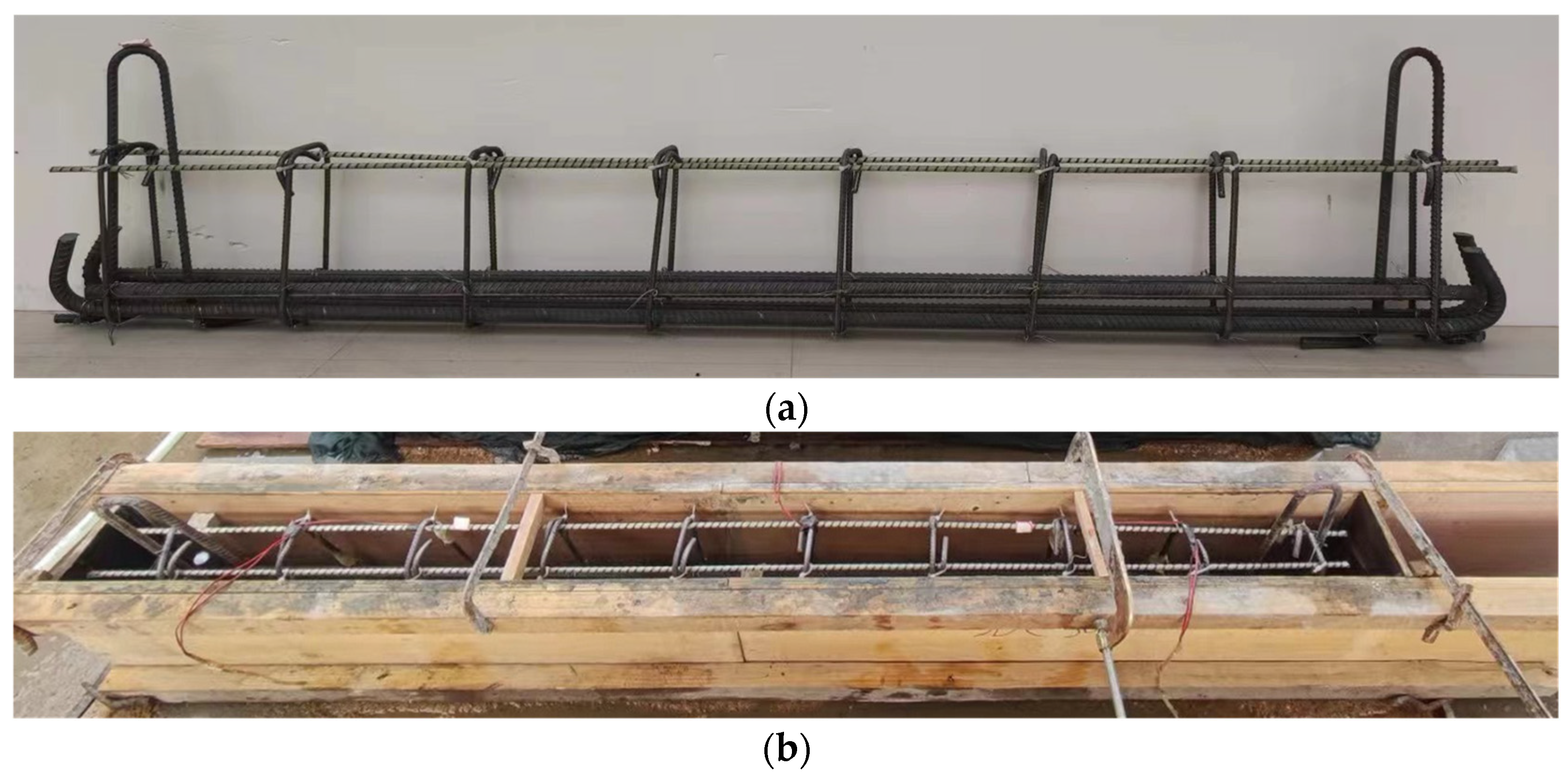
The concrete cover thickness of the beam was 20 mm. The stirrups in the beams were HRB400 steel bars with a diameter of 10 mm. The rare-reinforced beam had two 8 mm diameter HRB500 tensile steel bars, the balanced-reinforced beam had two 16 mm diameter HRB500 tensile steel bars, and the over-reinforced beam had four 20 mm diameter HRB500 tensile steel bars. Additionally, two 8 mm diameter fiber-reinforced polymer (FRP) bars were placed in the compression zone as erection bars, though their impact on the mechanical properties of the test beam was neglected. Figure 2 shows the dimensions and detailed reinforcement of the composite beams. The pictures of the reinforcement cage and pouring formwork of the composite beam are presented in Figure 3.

2.4. Specimen Testing and Basic Mechanical Properties

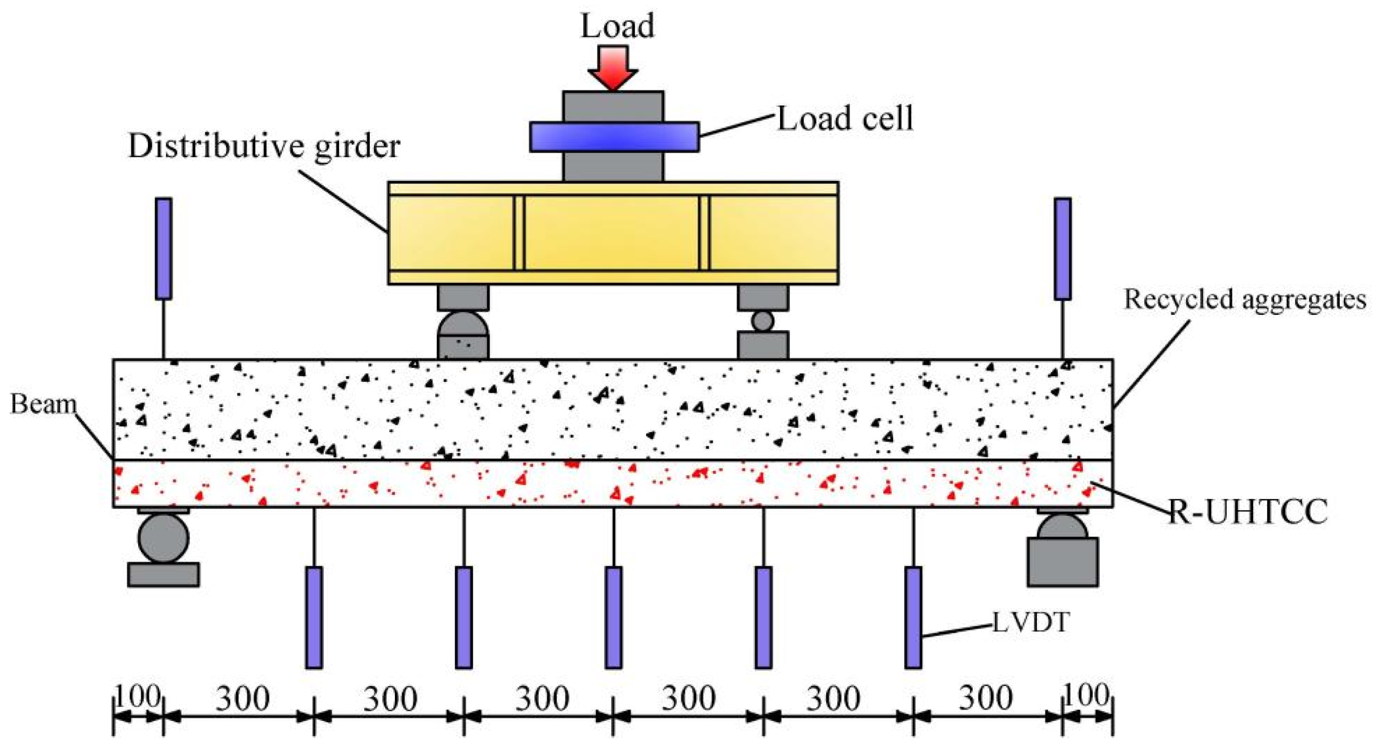
All beams were tested under four-point bending load using a 200 kN electro-hydraulic servo testing machine. Seven linear variable differential transformers were used to measure the midspan deflection of the beams. To monitor the strain evolution of the longitudinal reinforcement, three strain gauges were applied to the balanced-reinforced beam, and four to the over-reinforced beam. The arrangement of the strain gauges is depicted in Figure 2. The tests were conducted under displacement control, with a loading rate of 0.2 mm per minute. Before beam cracking, the load increment was set at 5 kN, which was increased to 10 kN after cracking. When the load increased to a certain value, the crack width of the composite beam was measured by a crack width detector, and the crack development was marked using a marker pen. The beam was considered to have failed when the load decreased to 85% of the ultimate bearing capacity. Figure 4 shows the measuring device and loading diagram of the beam. Figure 5 shows the crack width detector used in this experiment.
During the casting of the composite beams, accompanying blocks were cast simultaneously to assess the basic mechanical properties of concrete. For each mix proportion of recycled concrete, six cubic specimens with dimensions of 150 mm × 150 mm × 150 mm were cast to determine the cube compressive strength (fcu) and splitting tensile strength (fst), while six prism specimens with dimensions of 150 mm × 150 mm × 300 mm were cast to determine the axial compressive strength (fco) and elastic modulus (Ec). For R-UHTCC, six cubic specimens with dimensions of 100 mm × 100 mm × 100 mm were cast to evaluate the cube compressive strength and splitting tensile strength, and six prism specimens with dimensions of 100 mm × 100 mm × 300 mm were cast to assess the axial compressive strength and elastic modulus. All beams were demolded 24 h after pouring and then placed in an indoor environment for 28 days of curing. The indoor environment had an average temperature of 20 °C and an average relative humidity of 50%. All accompanying specimens were cured under conditions identical to those of the test beams and were tested simultaneously. Table 7 lists the test results of the recycled concrete and R-UHTCC. It should be noted that the splitting tensile strength of R-UHTCC exceeded that of recycled concrete at the same strength grade, while its elastic modulus was significantly lower. The main reason for this is that R-UHTCC does not contain coarse aggregates.

3. Experimental Results and Discussion

3.1. Failure Mode and Crack Width

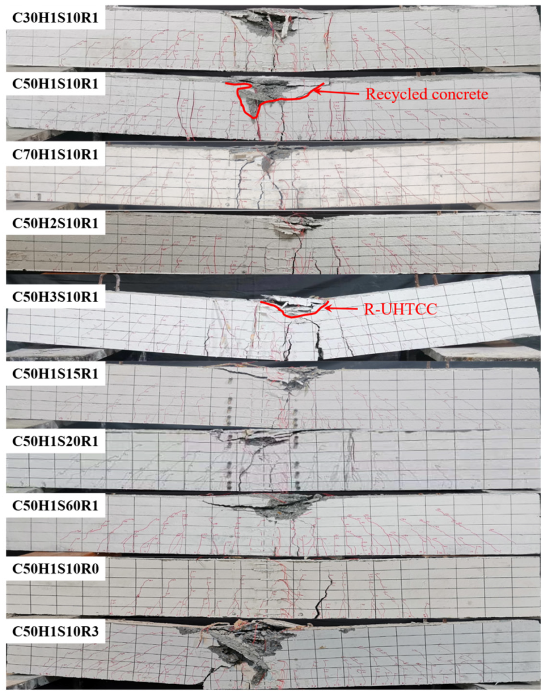
The failure modes of 10 R-UHTCC and recycled concrete composite beams are presented in Figure 6. The balanced-reinforced composite beams exhibited tensile-controlled failure and demonstrated good ductility. The failure process of the balanced-reinforced composite beams can be characterized by four distinct stages. In the first stage, the beams were uncracked and primarily in the elastic stage, with the bridging effects of polyvinyl alcohol fibers being minimal. In the second stage, cracks initially appeared in the pure bending region and progressively propagated upward as the load increased. As the load increased, shear cracks developed in the shear span. All beams displayed fine and dense cracking, as shown in Figure 6. Compared to composite beams with a 100 mm R-UHTCC layer height, those with 200 mm and 300 mm R-UHTCC layers exhibited slower crack propagation during loading. After the tensile reinforcement yielded, the beams transitioned into the third stage. At this point, horizontal microcracks began to form in the compression zone. As the load further increased, the main cracks in the constant bending moment zone expanded rapidly, and the deflection of the test beam also increased rapidly. The horizontal cracks in the compression zone continued to widen. After the beam reached its ultimate load, the main cracks in the constant moment zone connected with the horizontal cracks in the compression region, resulting in concrete crushing in the compression zone. Figure 6 shows that the concrete crushing area of the beams decreased as concrete strength increased. Furthermore, test beams with stirrups in the pure bending region exhibited a smaller concrete crushing area compared to those without stirrups, indicating that both increased concrete strength and the presence of stirrups improved the compressive performance of the concrete. In the fourth stage, the beams entered the failure stage. As loading continued, the midspan deflection and main crack rapidly increased, while the bearing capacity decreased. The polyvinyl alcohol fibers at the crack were progressively pulled out, and the test beam exhibited good ductility. When the bearing capacity of the beam decreased to 85% of its ultimate capacity, the test beam was considered invalid.
For rare-reinforced and over-reinforced composite beams, the failure modes were characterized by brittle failure. In the case of the rare-reinforced beam C50H1S10R0, failure did not occur immediately upon reaching the cracking load. Instead, multiple fine cracks developed in the constant moment zone and shear span of the beams. As the load increased, the width of the primary crack expanded rapidly. Upon reaching the ultimate load, the tensile reinforcement at the main crack ruptured. At this point, the main crack nearly penetrated the entire beam section, while the concrete in the compression zone remained intact. The rare-reinforced R-UHTCC and recycled concrete composite beam exhibited a brief load growth after cracking, although this process was relatively short-lived. In contrast, the destructive process of the over-reinforced composite beam C50H1S10R3 resembled that of a typical ordinary concrete over-reinforced beam. Upon reaching the ultimate bearing capacity, the compressed concrete suddenly crushed, resulting in a rapid loss of bearing capacity. At this stage, numerous fine cracks appeared in the tensile zone. The tensile reinforcement remained elastic, while the crushing depth of the concrete was significantly greater than that of the balanced-reinforced beam, indicating a brittle failure mode. Furthermore, for all test beams, nearly all cracks extended from the R-UHTCC layer to the recycled concrete layer, as shown in Figure 6, highlighting the strong bonding properties between the R-UHTCC and the recycled concrete.
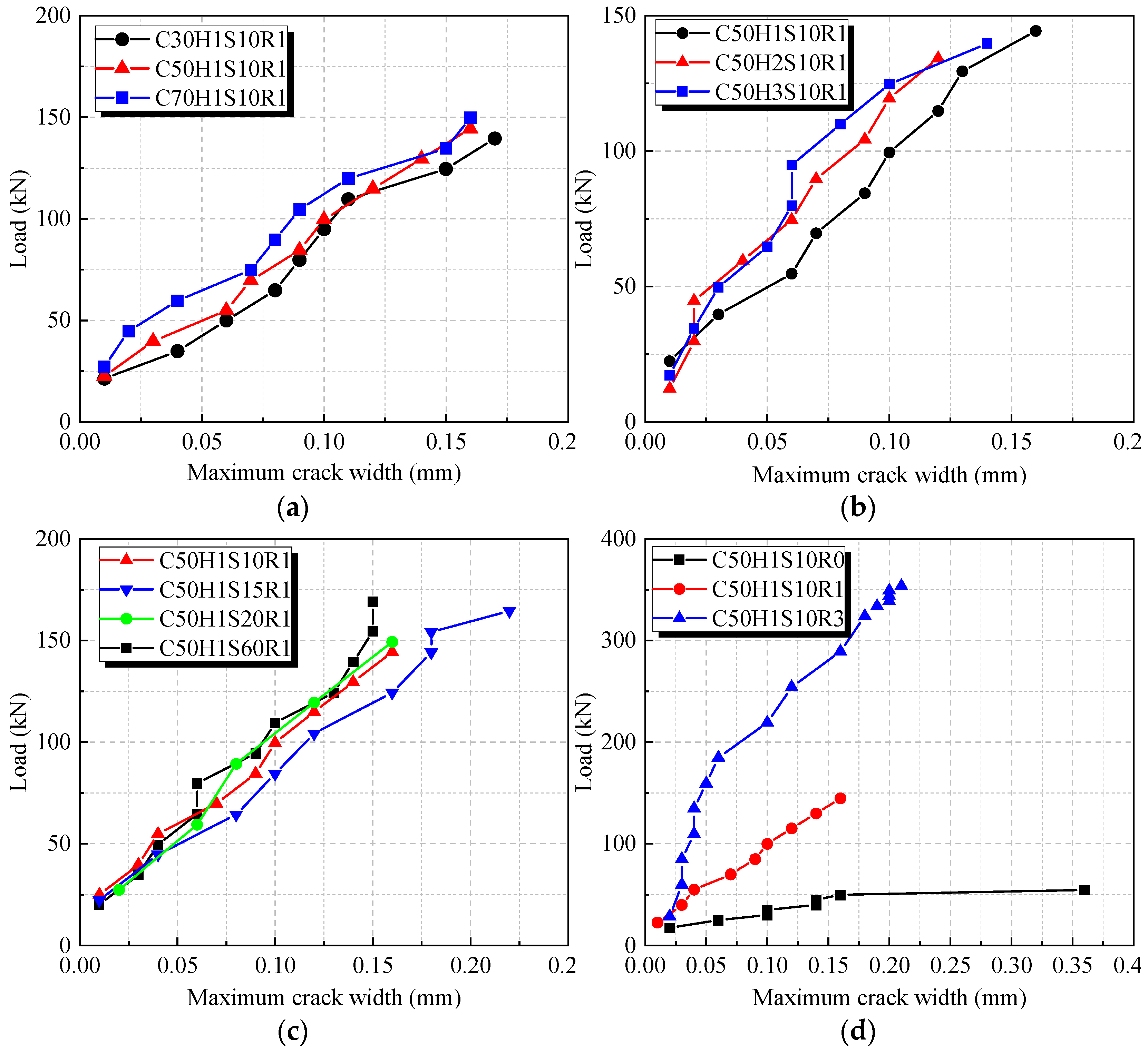
Figure 7 presents the load-maximum crack width curves of the beams. As shown, under the same load, the maximum crack width of beams decreases as the concrete strength grade increases. The main reason is that the higher concrete strength increases the stiffness of the composite beams, therefore reducing the deformation and crack width of the beams. The maximum crack width shows a decreasing trend with the increasing R-UHTCC layer height. Compared to the beams with the R-UHTCC layer height of 100 mm, the maximum crack width of the beams with the R-UHTCC layer height of 200 mm decreased by 24.3% under the load of 80 kN. However, with the further increase in R-UHTCC layer height, the maximum crack width remained basically unchanged. This can be explained by the fact that the effect of concrete in the compression zone on the crack width was not significant. Therefore, when the R-UHTCC layer reaches a certain height, its influence on crack width gradually weakens. The stirrup spacing in the pure bending region had no obvious influence on the crack width of the beam, while the maximum crack width decreased with the increasing reinforcement ratios under the same load. Furthermore, it can be observed that the maximum crack width at 70% of the ultimate bearing capacity was still less than 0.2 mm for all balanced-reinforced composite beams, which fully meets the requirements of the code for limiting the maximum crack width of RC bending members under the serviceability limit state in harsh environments [43]. Therefore, the R-UHTCC-recycled concrete composite beams can be used in harsh environments to improve the durability of the structure.

3.2. Flexural Capacity of Beams

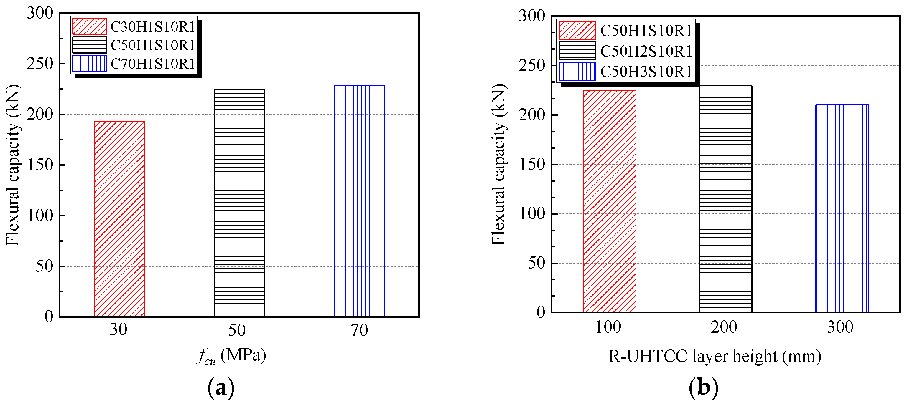
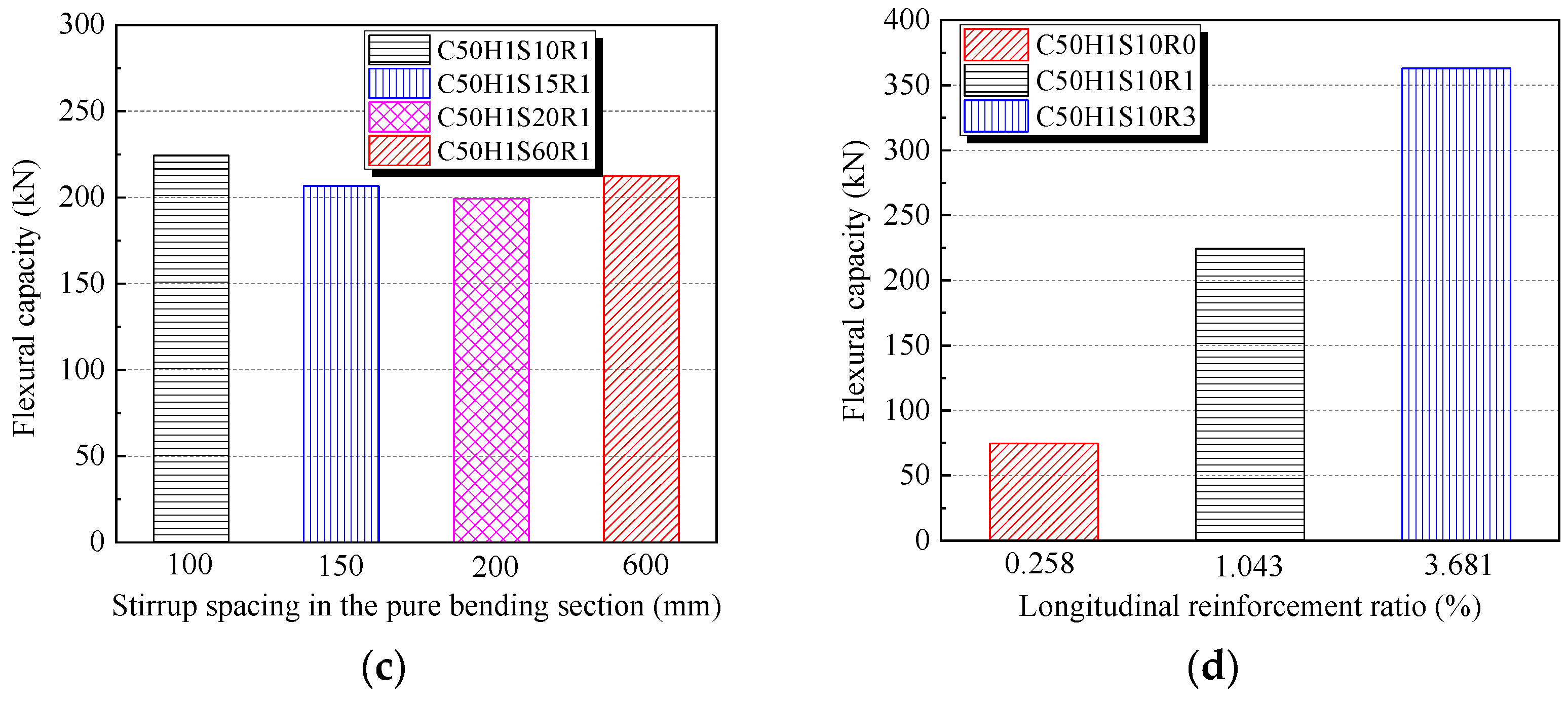
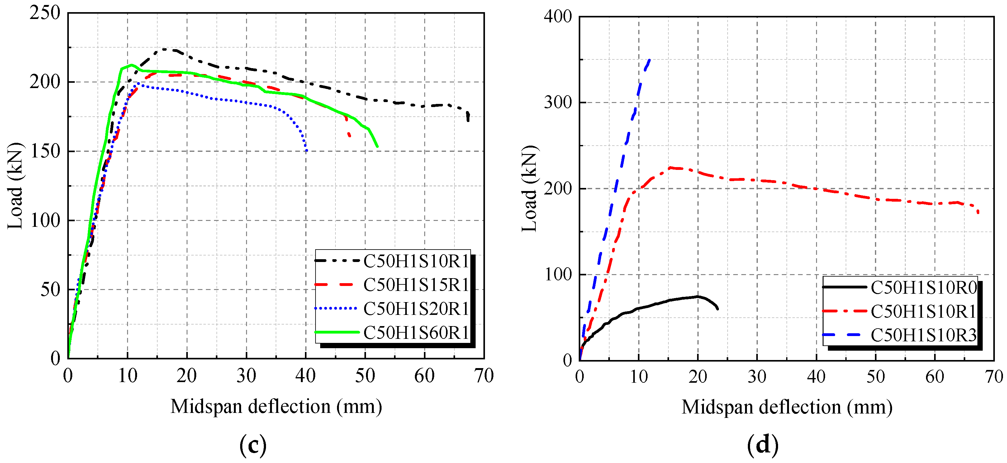
The flexural capacity of R-UHTCC and recycled concrete composite beams is presented in Figure 8. The flexural capacity increases with the concrete strength, as shown in Figure 8a. Compared to the C30 concrete-strength beam, the flexural capacities of the C50 and C70 concrete-strength beams increased by 16.5% and 18.8%, respectively. However, the height of the R-UHTCC layer showed minimal impact on the flexural capacity. For example, the beam with an R-UHTCC layer height of 200 mm exhibited only a 2.3% increase in flexural capacity compared to the beam with a 100 mm R-UHTCC layer. When the R-UHTCC was used across the entire beam section, the flexural capacity was the lowest. This can be explained by the fact that the flexural capacity of the composite beam is influenced not only by the concrete in the tensile zone and the longitudinal reinforcement but also by the concrete in the compression zone. While the high tensile strength and toughness of R-UHTCC improve the flexural capacity in the tensile zone, these properties cannot be fully utilized in the compression zone. Furthermore, the elastic modulus of R-UHTCC is considerably lower compared to the recycled concrete used in this study, leading to lower compressive stress in the compression zone of the beam. As a result, the flexural capacity of the full-section R-UHTCC beam is lower than that of composite beams that incorporate R-UHTCC only in the tensile zone. Therefore, for engineering applications, it is recommended to use R-UHTCC in the tensile zone of recycled concrete beams. It can be seen from Figure 8c that the flexural capacity also shows a decreasing trend with increasing stirrup spacing in the pure bending section. Specifically, the flexural capacities of the beams with stirrup spacings in the pure bending section of 150 mm, 200 mm, and no stirrups decreased by 7.9%, 11.2%, and 5.4%, respectively, compared to the beam with a 100 mm stirrup spacing. Furthermore, the flexural capacity improves significantly with the increase in reinforcement ratio, as shown in Figure 8d. Compared to the beam with a longitudinal reinforcement ratio of 0.258%, the flexural capacities of the beams with reinforcement ratios of 1.043% and 3.68% increased by 27.3% and 64.6%, respectively. The standard deviations and coefficients of variation of the flexural capacity for each series of beams were also calculated in this paper. The standard deviations and coefficients of variation of the flexural capacity were 16.13 and 0.075 for the different concrete strength grade series, 8.03 and 0.036 for the different R-UHTCC layer height series, 9.17 and 0.044 for the different stirrup spacing series, and 117.85 and 0.534 for the different longitudinal reinforcement ratio series. This indicates that the longitudinal reinforcement ratio has the most significant influence on the flexural capacity of the composite beams, followed by concrete strength. The influence of R-UHTCC layer height and stirrup spacing is relatively small. This phenomenon should be considered in the bearing capacity design of the composite beams.

3.3. Load Deflection Response of Beams

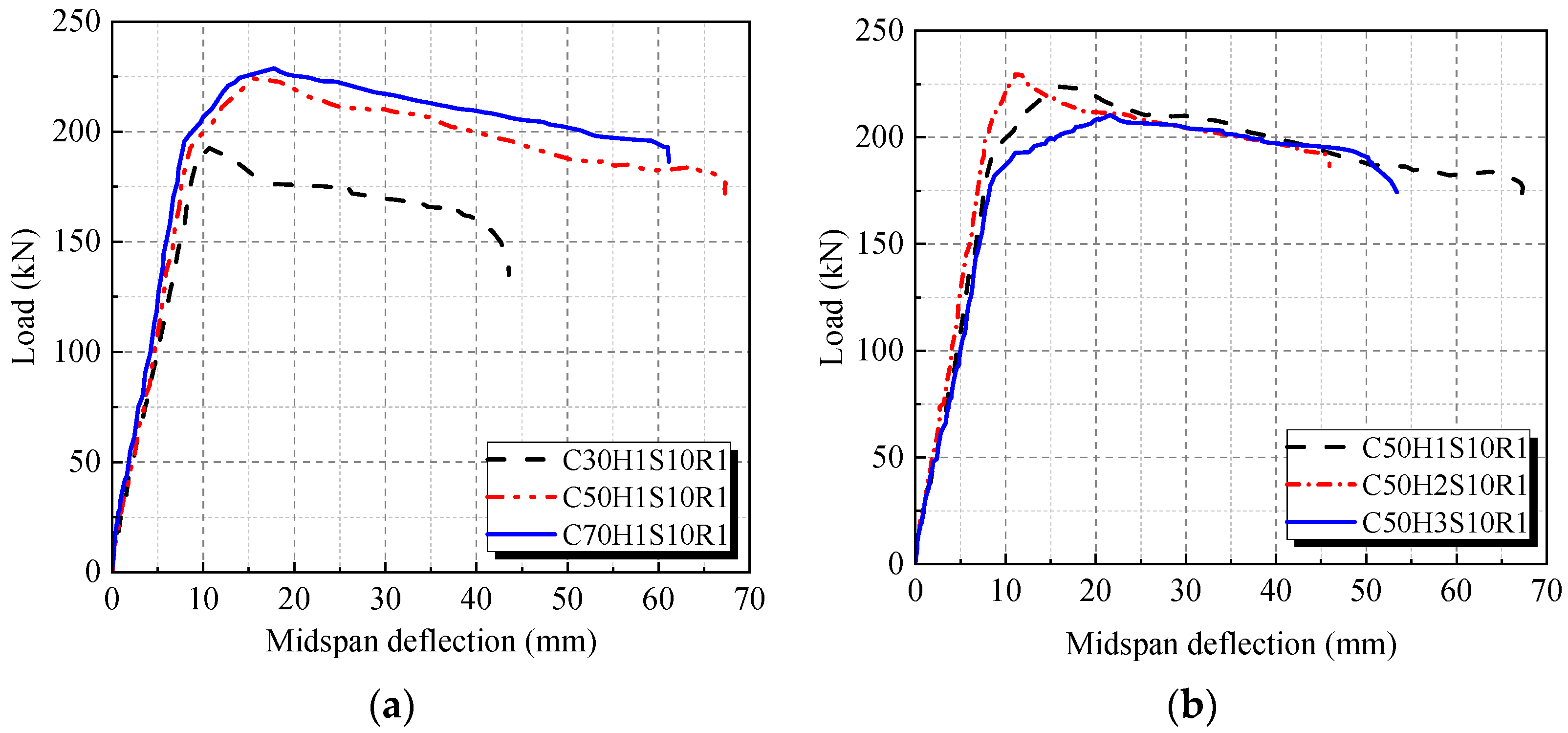
The load-deflection curves of the R-UHTCC and recycled concrete composite beams are presented in Figure 9. The development of midspan deflection can be characterized by four stages: elastic, cracking, yielding, and failure. Before cracking, the beam was in the elastic stage, and the deflection increased linearly with the applied load. Upon cracking, the stiffness decreases slightly; however, unlike conventional RC beams, the reduction in stiffness of the R-UHTCC and recycled concrete composite beams is minimal, and no substantial increase in deflection occurs at the cracking point. This is mainly attributed to the polyvinyl alcohol fibers bridging the cracks, maintaining tensile stress, as well as the multi-cracking behavior of R-UHTCC. During the cracking stage, the midspan deflection of beams continued to increase linearly with the load. As the load approaches approximately 80% of the beam’s ultimate bearing capacity, the tensile reinforcement begins to yield, causing the bearing capacity to increase slowly while deflection increases rapidly, and stiffness decreases significantly. In the failure stage, the midspan deflection of beams increased rapidly while the bearing capacity declined slowly. Notably, the R-UHTCC and recycled concrete composite beams exhibited good ductility, primarily due to the excellent elongation ability of the polyvinyl alcohol fibers, which continued to support the load even after the beam reached its maximum capacity.
The load-deflection curves of beams with different concrete strength grades are presented in Figure 9a. Prior to cracking, the load-deflection curves were almost coincident. After cracking, the stiffness of the beams gradually decreased. The midspan deflection of the beams decreased as the concrete strength increased under the same load. Compared to beams with concrete strength grades of C50 and C70, the beam with a C30 concrete grade experienced a sharp decline in load capacity after reaching its ultimate bearing capacity. This resulted from the lower tensile strength and ultimate strain of the C30 R-UHTCC [44]. Therefore, it is recommended to use higher-strength R-UHTCC in composite beams. The load-deflection curves of beams with different R-UHTCC layer heights are presented in Figure 9b. The stiffness of the beams after cracking initially increased and then decreased as the R-UHTCC layer height increased from 100 mm to 300 mm. For composite beams with R-UHTCC in the tensile zone, the bridging force of polyvinyl alcohol fibers increased with the rising R-UHTCC layer height. Consequently, the stiffness of the beam with a 200 mm R-UHTCC layer height was greater than that of the beam with a 100 mm layer height. However, when the R-UHTCC layer covered the full beam section, the stiffness was lowest. This was primarily because the elastic modulus of the R-UHTCC used in this study is significantly lower than that of recycled concrete, which aligns with findings reported by Ding [45]. Additionally, it can be seen from Figure 9b that the deflection of the beam with a 300 mm R-UHTCC layer height increased significantly from the yielding point to the maximum capacity point, with the deflection at ultimate capacity being notably higher than that of the other beams. This behavior is attributed to the strain-hardening characteristics of R-UHTCC. For beams with different stirrup spacings in the constant moment region, the effects of stirrup spacing on the load-deflection responses were minimal. The development of the load-deflection curves for these beams was largely consistent, as shown in Figure 9c. The load-deflection curves of beams with different longitudinal reinforcement ratios are presented in Figure 9d. The over-reinforced beam typically exhibited brittle failure, while the rare-reinforced beam showed a gradual rise in bearing capacity after cracking, with the ultimate load significantly exceeding the cracking load. This behavior is primarily due to the bridging effect of fibers after the beam has cracked. Therefore, it can be concluded that incorporating R-UHTCC within a specific height range in the tensile zone of a flexural beam can significantly improve its ductility.

3.4. Ductility of Beams

To evaluate the effects of R-UHTCC on the ductility of balanced-reinforced composite beams, this study used the ductility index of the beams, which is expressed as follows:
μ Δ = Δ 0.85 Δ y
where Δ0.85 is the midspan deflection of beams when the bearing capacity of the test beam decreases to 85% of the ultimate load; Δy is the midspan deflection at the yield point.
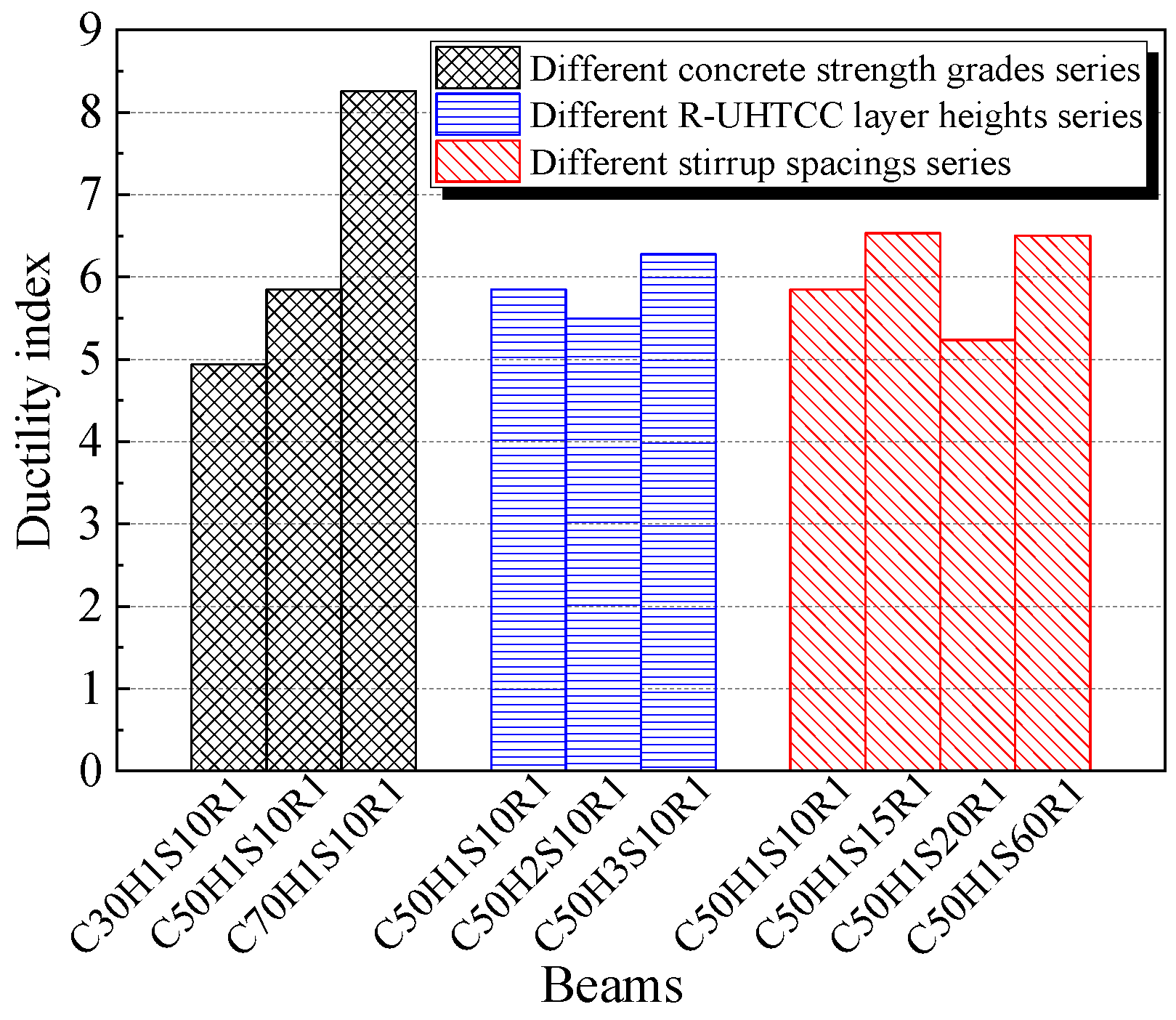
The ductility index of the balanced-reinforced composite beams is presented in Figure 10. As shown, the ductility index of all beams exceeds four. For normal RC flexural beams, the experimental values of the deflection ductility factor generally range from two to six [46]. Therefore, it can be concluded that the R-UHTCC and recycled concrete composite beams exhibited excellent ductility. Additionally, the ductility index increases with the concrete strength grade. Specifically, compared to the beam with a concrete strength grade of C30, the ductility index of the beams with C50 and C70 concrete strength grades increased by 18.5% and 67.3%, respectively. The ultimate tensile strain also increases with the R-UHTCC strength [44], indicating that higher R-UHTCC strength enhances the ductility of the composite beams. However, the ductility index of the beam with the full-section R-UHTCC was only 7.2% greater than that of the beam with a 100 mm R-UHTCC layer height, suggesting that good ductility can be achieved using R-UHTCC only within a certain height range in the tensile zone of the beam. Furthermore, it can be seen from Figure 10 that the effect of stirrup spacing on beam ductility was inconsistent, probably because of the variability in the experimental results. The standard deviations and coefficients of variation of the ductility were 1.4 and 0.221 for the different concrete strength grade series, 0.32 and 0.054 for the different R-UHTCC layer height series, and 0.53 and 0.088 for the different stirrup spacing series. This indicates that the concrete strength has the most significant influence on the ductility of the composite beams, while the R-UHTCC layer height has minimal impact on the beam’s ductility.

3.5. Load-Strain Curves

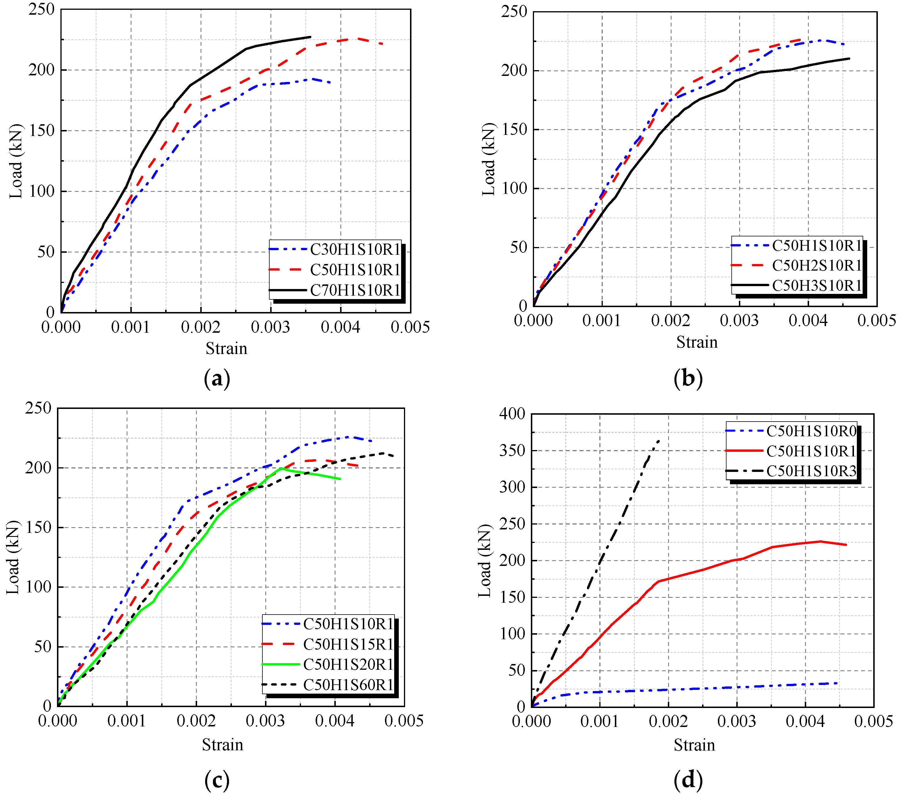
The development of the nominal strain in the longitudinal reinforcement of beams within the pure bending section is presented in Figure 11. The nominal strain was obtained by averaging the test values from strain gauges attached to the longitudinal reinforcement. Due to the failure of some strain gauges as the test beams approached or reached their peak load, the figure only presents the strain data before the beams reached their maximum load. As observed, the strain development of the longitudinal reinforcement closely followed the trend of the midspan deflection. Before cracking, the strain in the steel bar increased linearly with load. After the beam cracked, the slope of the strain curves slightly increased. Once the yield point was reached, strain increased rapidly with further loading. For beams with different concrete strengths, the strain of the steel bars decreased as the concrete strength increased under the same load. Specifically, the strain of the steel bars of beams with C50 and C70 concrete strength grades decreased by 8.8% and 21.6%, respectively, compared to the beam with C30 concrete strength, when the load reached 100 kN. The effects of R-UHTCC layer height on steel bar strain were minimal for beams with 100 mm and 200 mm layer heights. In contrast, the strain of the steel bars of the full-section R-UHTCC beam significantly increased under the same load. This increase is attributed to the lower elastic modulus of R-UHTCC, which reduces beam stiffness. As shown in Figure 11c, stirrup spacing did not significantly influence the steel bar strain. Additionally, the strain data for the over-reinforced beam in the loading process showed no yielding of the steel bars, indicating a brittle failure. In the case of the rare-reinforced beam, premature yielding of the steel bars led to the early failure of the strain gauges, meaning Figure 11d does not provide the complete load-strain curve for this beam up to its ultimate bearing capacity.

3.6. Stiffness Calculation

The experimental results indicate that R-UHTCC influences the stiffness of composite beams. However, methods for calculating the stiffness of composite beams incorporating R-UHTCC and recycled concrete are seldom reported. This study presents a stiffness calculation approach based on the effective moment of inertia.
For ordinary RC beams, the effective moment of inertia can be calculated as follows [43]:
I e = I g M a 2 / 3 M c r I c r 1 2 / 3 M c r M a 2 1 I c r I g     M a > 2 / 3 M c r
where Ig is the gross moment of inertia of the uncracked section; Ma is the bending moment borne by the beam under the normal service loading; Mcr is the cracking moment; Icr is the moment of inertia of the cracked section.
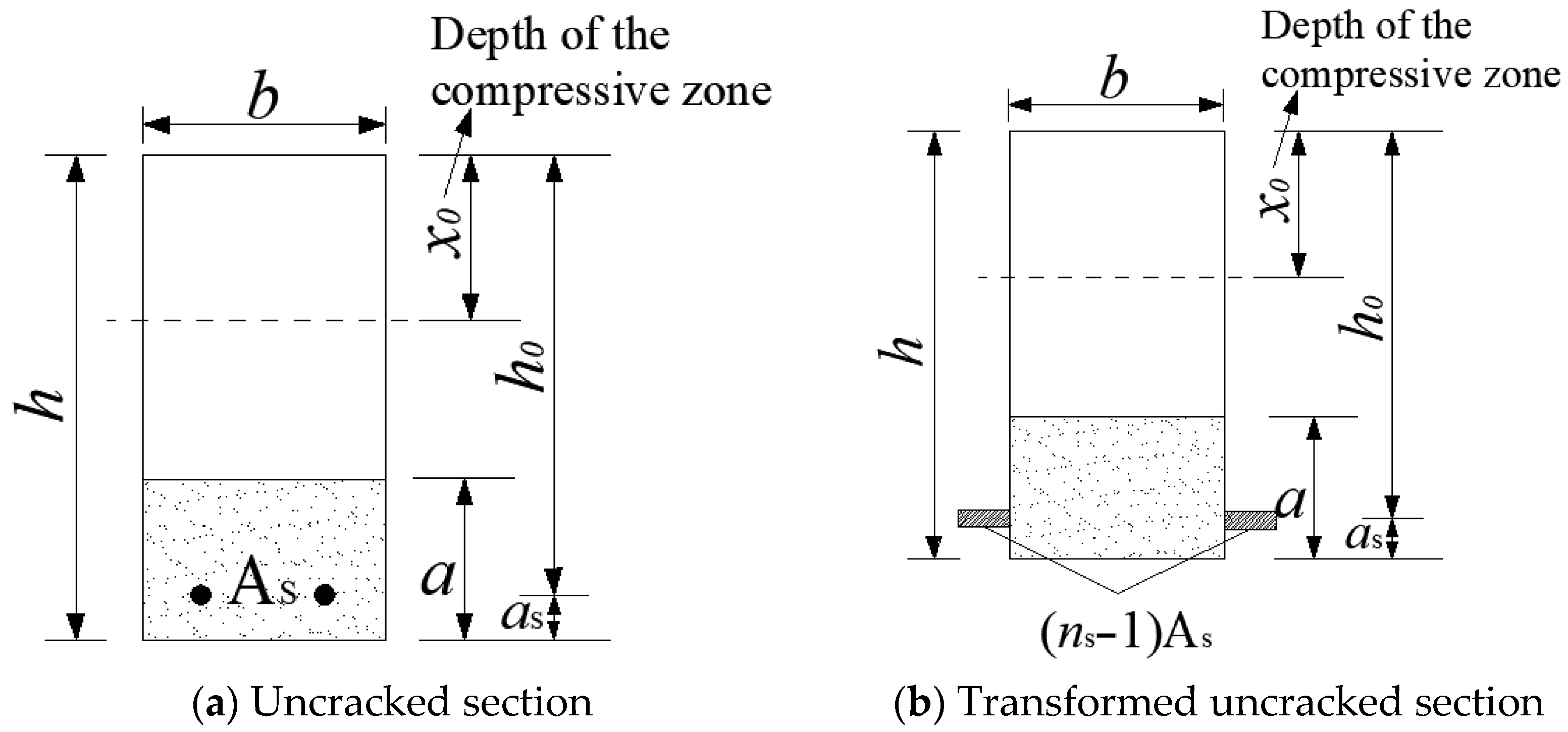
Figure 12 presents the transformation diagram of the uncracked section for R-UHTCC and recycled concrete composite beams. Due to the differing elastic moduli of R-UHTCC and recycled concrete, the R-UHTCC section in the tensile zone must also be transformed. According to the equal area moment of the neutral axis in the tensile and compressive zones, the following equation can be derived:
b ( h x 0 a ) 2 2 + n s 1 A s h 0 x 0 + n r a b h x 0 a 2 = b x 0 2 2
where b and h refer to the width and height of the beam section, respectively; x0 is the depth of the compressive zone for the uncracked section; a is the R-UHTCC layer height; ns is the elastic modulus ratio of the tensile reinforcement to the recycled concrete; nr is the elastic modulus ratio of the R-UHTCC to the recycled concrete; h0 is the effective height of the beam.
According to Equation (3), x0 and Ig of the composite beam can be obtained as follows:
x 0 = 1 2 b h 2 + 1 2 b a 2 b a h + n s 1 A s h 0 + ( h a 2 ) n r b a b h b a + n s 1 A s + n r b a
I g = b 3 x 0 3 + h x 0 a 3 + n s 1 A s h 0 x 0 2 + n r b a 3 12 + n r a b h x 0 a 2 2
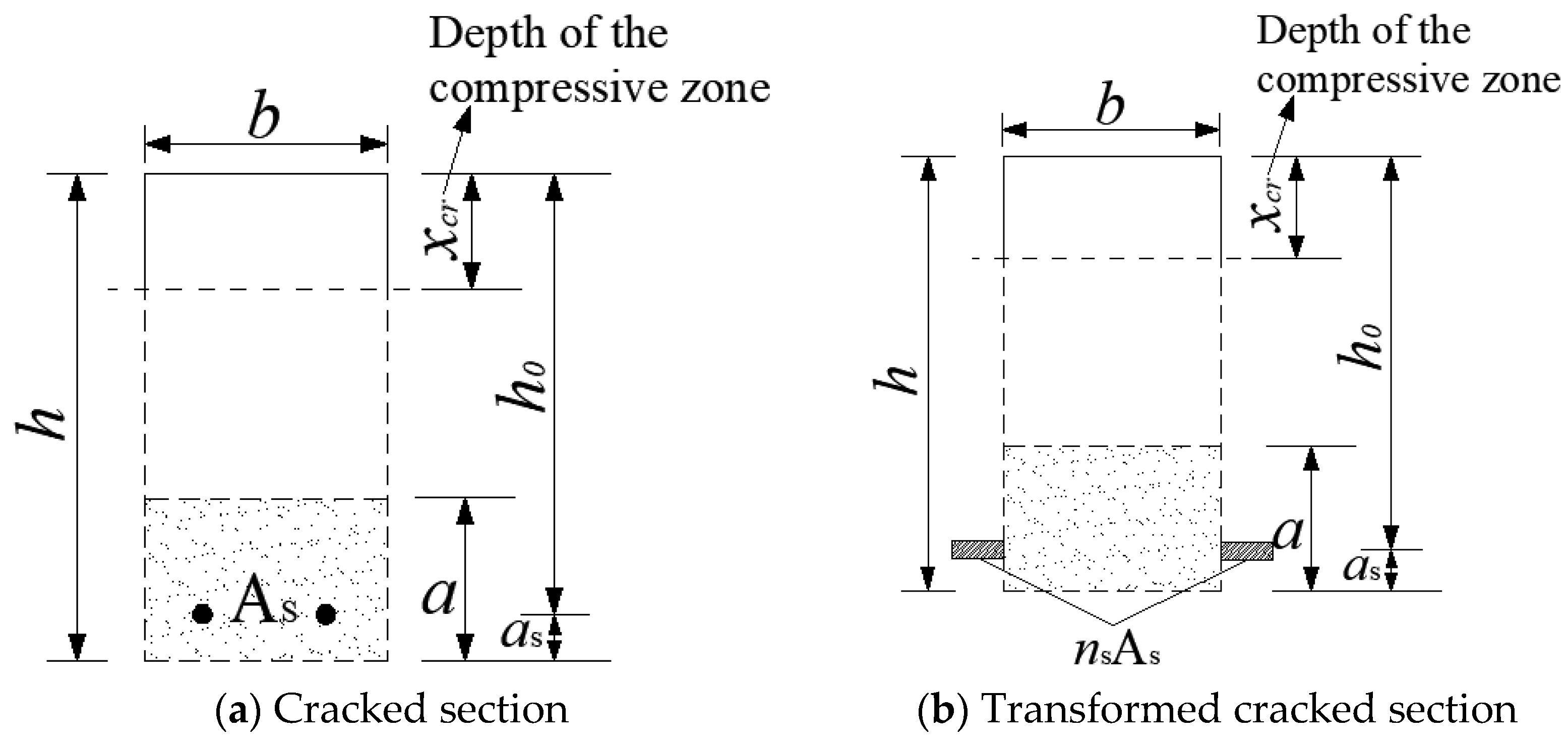
Figure 13 illustrates the transformation diagram of the cracked section for the composite beam. For normal RC beams, the concrete’s contribution to the moment of inertia in the tensile zone is neglected after cracking. According to the equal area moment of the neutral axis in the tensile and compressive zones, the depth of the compressive zone and moment of inertia for the cracked section of the normal RC beam can be calculated as follows:
x c r = n s A s + n s A s 2 + 2 b n s A s h 0 b
I c r = b ( x c r ) 3 3 + n s A s h 0 x c r 2
where xcr and Icr are the depth of the compressive zone and moment of inertia for the cracked section of the normal RC beam, respectively.
However, in the case of the R-UHTCC and recycled concrete composite beam, the R-UHTCC can still withstand tensile stress after the beam has cracked. Therefore, the influence of R-UHTCC on the moment of inertia of the cracked section must be considered. It is evident that these effects will increase with the increase in the R-UHTCC layer height. Therefore, this study assumes a linear relationship between the cracked moment of inertia and the ratio of the R-UHTCC layer height to the total section height. The moment of inertia for the cracked section of the composite beam can be calculated as follows:
I c r = ξ a h I c r = ξ a h b ( x c r ) 3 3 + n s A s h 0 x c r 2
where ξ is a factor used to correct the effects of R-UHTCC on the cracked moment of inertia of the composite beam.
Substitute Equations (5) and (8) into Equation (1), and the stiffness of the beam under normal service conditions can be calculated as follows:
B R = E c I e = E c I g M a 2 / 3 M c r E c ξ I c r a / h 1 2 / 3 M c r M a 2 1 ξ a I c r h I g M a > 2 / 3 M c r
where Ec is the elastic modulus of recycled concrete.
By analyzing the test results, it was found that the correction factor ξ is primarily related to the R-UHTCC layer height. Through regression analysis, ξ is expressed as follows:
ξ = 2.1 a / h + 2.55
Currently, research on the flexural performance of R-UHTCC and recycled concrete composite beams is relatively limited. The empirically derived correction factor ξ only considers the influence of the ratio of R-UHTCC to beam section height. Other influencing factors, such as the polyvinyl alcohol fiber volume fraction, beam geometry, and loading conditions, were not considered in this paper. Therefore, further research is encouraged in the future to expand the available test data and loading conditions to refine the factor ξ and improve its applicability and range.
Based on the material mechanical theory, the midspan deflection of the composite beam under four-point bending load in normal service conditions can be expressed as follows:
f = 6.81 P l 0 3 384 B R
where P is the load applied to the beam under the normal service condition; l0 is the beam’s clear span.
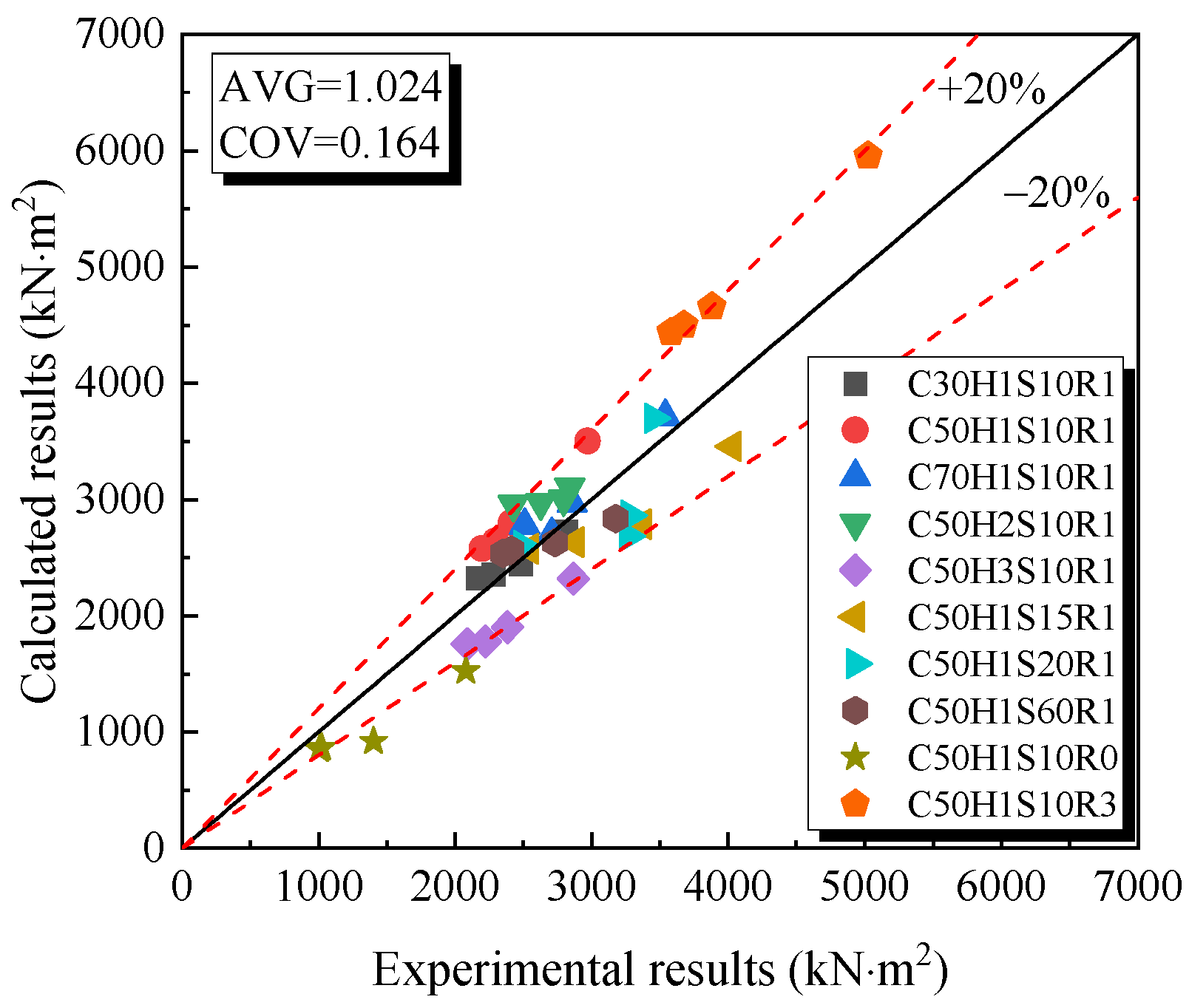
Substituting the midspan deflection test results of the 10 composite beams in this experiment into Equation (11), the experimental stiffness of the beams under normal service conditions can be obtained. Figure 14 presents a comparison between the calculated and experimental stiffness values based on Equation (9) for beams subjected to different loads. The average ratio of experimental to calculated results is 1.024, accompanied by a coefficient of variation of 0.164, indicating that the calculated values align well with the experimental results.

4. Conclusions

The flexural behavior of R-UHTCC and recycled concrete composite beams was investigated in this study. According to the experimental results and analysis, the main conclusions are as follows:
(1) The failure mode of the balanced-reinforced composite beam was dominated by tensile-controlled failure, characterized by the yielding of tensile reinforcement and concrete crushing in the compressive zone. In contrast, the rare-reinforced and over-reinforced composite beams exhibited brittle failure. Additionally, the rare-reinforced composite beam demonstrated a load increase after cracking, with the ultimate load significantly exceeding the cracking load.
(2) The maximum crack width of the composite beams decreased with the increase in concrete strength grade, R-UHTCC layer height, and reinforcement ratios. Compared to beams with an R-UHTCC layer height of 100 mm, the maximum crack width of beams with an R-UHTCC layer height of 200 mm decreased by 24.3% under a load of 80 kN. Furthermore, the maximum crack width at 70% of the ultimate bearing capacity remained below 0.2 mm for all balanced-reinforced composite beams.
(3) The flexural capacity of R-UHTCC and recycled concrete composite beams increased with increasing concrete strength and reinforcement ratio, while it decreased with the increasing stirrup spacing in the constant moment zone. The flexural capacity of the beam increased by up to 18.8% when the concrete strength grade rose from C30 to C70. Compared to the beam with a longitudinal reinforcement ratio of 0.258%, the flexural capacities of beams with reinforcement ratios of 1.043% and 3.68% increased by 27.3% and 64.6%, respectively. The height of the R-UHTCC layer had minimal impact on the flexural capacity. Beams with R-UHTCC layers of 100 mm and 200 mm exhibited similar flexural capacities, whereas beams with a full-section R-UHTCC layer had the lowest flexural capacity.
(4) The R-UHTCC and recycled concrete composite beams exhibited good ductility. The ductility index for all beams exceeded four and increased with increasing concrete strength. The maximum increase in the ductility index reached 67.3% as the concrete strength grade increased from C30 to C70. The height of the R-UHTCC layer had little impact on the ductility of the beams.
(5) Compared to the pre-cracking state, the stiffness degradation of the composite beams after cracking was not significant. A stiffness calculation method derived from the effective moment of inertia was proposed and aligns well with the experimental results.
(6) The flexural behavior, including flexural capacity, stiffness, and ductility of the composite beam with an R-UHTCC layer height of 100 mm, was similar to that of the beam with a 200 mm R-UHTCC layer and even better than that of the full section R-UHTCC beam. It is recommended to use an R-UHTCC layer that constitutes one-third of the beam section height in the tensile zone to strengthen recycled concrete beams. Furthermore, the improvement in durability of recycled concrete beams by incorporating R-UHTCC should not be overlooked, and further research into the durability of R-UHTCC and recycled concrete composite beams is encouraged.
(7) The stiffness calculation method was based on the effective moment of inertia method outlined in the design code. Only limited test data from this experiment were used to verify its accuracy. Influencing factors, such as the polyvinyl alcohol fiber volume fraction, beam geometry, and loading conditions, were not considered in this paper. Therefore, further research is encouraged to expand the available test data to improve the applicability of the proposed method.
(8) This paper only conducted a monotonic four-point bending test of the composite beams. Real structures are often subjected to repeated or cyclic loads. It is well known that UHTCC exhibits good fatigue performance. Therefore, it is encouraged that future research include fatigue testing to investigate whether the properties of R-UHTCC could enhance the fatigue or cyclic performance of the composite beams.

Author Contributions

Conceptualization, D.W.; Methodology, Z.G., D.G. and L.Y.; Software, Z.G.; Validation, G.C.; Formal analysis, D.W., Z.L. and Z.G.; Investigation, D.W. and D.G.; Resources, D.G.; Data curation, Z.L. and L.Y.; Writing—original draft, D.W. and Z.L.; Writing—review and editing, Z.G.; Visualization, Z.L.; Supervision, Z.G. and L.Y.; Project administration, D.G. and G.C.; Funding acquisition, D.W. and Z.G. All authors have read and agreed to the published version of the manuscript.

Funding

This research was funded by the National Natural Science Foundation of China (No. 52308292), Key Scientific Research Projects of Henan Colleges and Universities (No. 22A570010), Postdoctoral Science Foundation of China (Nos. 2023M743214 and 2024T170840), and Henan Institute of Science and Technology (No. 242102521013).

Conflicts of Interest

The authors declare no conflict of interest.

References

  1. Liu, X.; Asghari, V.; Lam, C.; Chien Hsu, S.; Xuan, D.; Cirelli Angulo, S.; John, V.M.; Basavaraj, A.S.; Gettu, R.; Xiao, J.; et al. Discrepancies in life cycle assessment applied to concrete waste recycling: A structured review. J. Clean. Prod. 2024, 434, 140155. [Google Scholar] [CrossRef]
  2. Hao, J.; Ma, W. Evaluating carbon emissions of construction and demolition waste in building energy retrofit projects. Energy 2023, 281, 128201. [Google Scholar] [CrossRef]
  3. Wu, L.; Sun, Z.; Yan, C. Modification of recycled aggregate and conservation and application of recycled aggregate concrete: A review. Constr. Build. Mater. 2024, 431, 136567. [Google Scholar] [CrossRef]
  4. Xiao, J.; Poon, C.; Wang, Y.; Zhao, Y.; Ding, T.; Geng Ye, T.; Li, L. Fundamental behavior of recycled aggregate concrete—Overview I: Strength and deformation. Mag. Concr. Res. 2022, 74, 999–1010. [Google Scholar] [CrossRef]
  5. Dang, J.; Zhao, J.; Dai, S.P.; Zhao, S. Durability and microstructural properties of concrete with recycled brick as fine aggregates. Constr. Build. Mater. 2020, 262, 120032. [Google Scholar] [CrossRef]
  6. Wang, B.; Yan, L.; Fu, Q.; Kasal, B. A Comprehensive Review on Recycled Aggregate and Recycled Aggregate Concrete. Resour. Conserv. Recycl. 2021, 171, 105565. [Google Scholar] [CrossRef]
  7. Abdo, A.; El-Zohairy, A.; Alashker, Y.; Badran, M.A.E.-A.; Ahmed, S. Effect of Treated/Untreated Recycled Aggregate Concrete: Structural Behavior of RC. Beams. Sustainability 2024, 16, 4039. [Google Scholar] [CrossRef]
  8. Soares, A.C.M.; Tavares, M.E.N. Shrinkage of concrete with recycled brick aggregates. Constr. Build. Mater. 2025, 491, 142485. [Google Scholar] [CrossRef]
  9. Liu, C.Y.; Qin, J.H.; Akbar, A. Study on flexural mechanical properties and size effect of recycled coarse aggregate concrete beams based on 3D mesoscopic simulation. Struct. Concr. 2025. [Google Scholar] [CrossRef]
  10. Ali, R.; El Ouni, M.H.; Liaqat, A.; Muhammad, A.; Babar, A.; Zeeshan, A.; Ben, K.N. Structural evaluation of recycled aggregate concrete circular columns having FRP rebars and synthetic fibers. Eng. Struct. 2022, 250, 113392. [Google Scholar] [CrossRef]
  11. Gu, Z.; Wang, J.; Gao, D.; Zhao, J. Effects of steel fibers on the flexural behavior of recycled concrete beam: Testing and analysis. J. Build. Eng. 2024, 85, 108718. [Google Scholar] [CrossRef]
  12. Niu, H.; Li, B.; Gao, J.; Xie, S. Effect of hybrid fibers on the flexural performance of high-strength recycled aggregate concrete beams. Struct. Concr. 2023, 25, 1. [Google Scholar] [CrossRef]
  13. Lu, Y.; Xiao, J.; Li, Y. 3D printing recycled concrete incorporating plant fibres: A comprehensive review. Constr. Build. Mater. 2024, 425, 135951. [Google Scholar] [CrossRef]
  14. Wang, C.; Xiao, J.; Liu, W.; Ma, Z. Unloading and reloading stress-strain relationship of recycled aggregate concrete reinforced with steel/polypropylene fibers under uniaxial low-cycle loadings. Cem. Concr. Compos. 2022, 131, 104597. [Google Scholar] [CrossRef]
  15. Gao, D.; Zhu, W.; Gu, Z.; Yang, L. Flexural capacity prediction of steel fiber reinforced concrete beam with recycled fine and coarse aggregate. Adv. Struct. Eng. 2023, 26, 1042–1058. [Google Scholar] [CrossRef]
  16. Wang, Y.; Cheng, J.; Wang, J. Flexural performance of recycled concrete beam reinforced with modified basalt fiber and nano-silica. Case Stud. Constr. Mater. 2023, 18, e02022. [Google Scholar] [CrossRef]
  17. Samer, G.; Bilal, H.; Elie, A. Structural and life cycle assessments of recycled aggregate concrete beams incorporating industrial hemp fibers. Struct. Concr. 2023, 24, 1. [Google Scholar] [CrossRef]
  18. Ibrahim, Y.E.; Fawzy, K.; Farouk, M.A. Effect of steel fiber on the shear behavior of reinforced recycled aggregate concrete beams. Struct. Concr. 2021, 22, 1861–1872. [Google Scholar] [CrossRef]
  19. Hossain, F.M.Z.; Pal, A.; Ahmed, K.S.; Bediwy, A.; Alam, M.S. Shear behavior of polypropylene fiber-reinforced concrete beams containing recycled aggregate and crumb rubber. J. Clean. Prod. 2023, 412, 137370. [Google Scholar] [CrossRef]
  20. Kachouh, N.; Maaddawy, T.E.; Hassan, H.E.; Ariss, B.E. Shear Behavior of Steel-Fiber-Reinforced Recycled Aggregate Concrete Deep Beams. Buildings 2021, 11, 423. [Google Scholar] [CrossRef]
  21. Nguyễn, H.H.; Choi, J.L.; Park, S.E.; Cha, S.L.; Huh, J.; Lee, B.Y. Autogenous healing of high strength engineered cementitious composites (ECC) using calcium containing binders. Constr. Build. Mater. 2020, 265, 120857. [Google Scholar] [CrossRef]
  22. Khan, M.K.I.; Lee, C.K.; Zhang, Y.X. Parametric study on high strength ECC-CES composite columns under axial compression. Columns axial Compress. J. Build. Eng. 2021, 44, 102883. [Google Scholar] [CrossRef]
  23. Luo, Q.; Zhang, J.; Lu, Z.; Wang, F.; Zhang, Y.; Liu, Z.; Jiang, J. A prediction model of the tensile properties of engineered cementitious composites (ECC) based on the continuous crack tracking algorithm. J. Build. Eng. 2023, 79, 107903. [Google Scholar] [CrossRef]
  24. Wu, F.; Zhao, B.; Cao, J.; Shen, X.; Wang, Z.; Lei, H.; Cui, Z. Experimental and theoretical investigations on flexural performance of hybrid fiber reinforced ECC-NC composite beams. Case Stud. Constr. Mat. 2024, 20, e03178. [Google Scholar] [CrossRef]
  25. Ge, W.; Ashraf, F.A.; Lu, W.; Cao, D. Flexural Performance of Steel Reinforced ECC-Concrete Composite Beams Subjected to Freeze–Thaw Cycles. Int. J. Concr. Struct. Mater. 2020, 14, 1–20. [Google Scholar] [CrossRef]
  26. Ge, W.; Ashraf, F.A.; Ji, X.; Cai, C.; Cao, D. Flexural behavior of ECC-concrete composite beams reinforced with steel bars. Constr. Build. Mater. 2018, 159, 175–188. [Google Scholar] [CrossRef]
  27. Maalej, M.; Li, V.C. Introduction of strain-hardening engineered cementitious composites in design of reinforced concrete flexural members for improved durability. ACI Struct. J. 1995, 92, 167–176. [Google Scholar] [CrossRef]
  28. Wang, N.; Xu, S. Flexural response of reinforced concrete beams strengthened with post-poured ultra high toughness cementitious composites layer. J. Cent. South Univ. 2011, 18, 932–939. [Google Scholar] [CrossRef]
  29. Yuan, F.; Pan, S.; Leung, C.K.Y. Flexural behaviors of ECC and concrete/ECC composite beams reinforced with basalt fiber-reinforced polymer. J. Compos. Constr. 2013, 17, 591–602. [Google Scholar] [CrossRef]
  30. Zhang, Y.; Ueda, N.; Nakamura, H.; Kunieda, M. Behavior investigation of reinforced concrete members with flexural strengthening using strain-hardening cementitious composite. ACI Mater. J. 2017, 114, 417–426. [Google Scholar] [CrossRef]
  31. Wu, C.; Li, V.C. CFRPECC hybrid for strengthening of the concrete structures. Compos. Struct. 2017, 178, 372–382. [Google Scholar] [CrossRef]
  32. Maalej, M.; Quek, S.T.; Ahmed, S.F.U.; Zhang, J.; Lin, V.W.J.; Leong, K.S. Review of potential structural applications of hybrid fiber engineered cementitious composites. Constr. Build. Mater. 2012, 36, 216–227. [Google Scholar] [CrossRef]
  33. Zhang, J.; Leung, C.K.Y.; Cheung, Y.N. Flexural performance of layered ECC-concrete composite beam. Compos. Sci. Technol. 2006, 66, 1501–1512. [Google Scholar] [CrossRef]
  34. Wang, X.; Yang, Q.; Peng, X.; Xia, K.; Xu, B. A Review of Mechanical Performance Studies on Composite Concrete Beams and Slabs. Materials 2025, 18, 3259. [Google Scholar] [CrossRef] [PubMed]
  35. Khan, S.W.; Ali, Y.; Khan, F.A.; Fahim, M.; Gu, A.; Ullah, Q.S. Shams-ul-Islam. Flexural Performance of Composite RC Beams Having an ECC Layer at the Tension Face. Period. Polytech. Civ. Eng. 2023, 67, 518–529. [Google Scholar] [CrossRef]
  36. Yousef, A.M.; Atef, N.H.; Tahwia, A.M. Flexural performance of functionally graded UHPFRC-NSC beams. Case Stud. Constr. Mater. 2024, 21, e03653. [Google Scholar] [CrossRef]
  37. Helal, K.A.; Tahwia, A.M.; Youssf, O. Assessment of the efficiency of hybrid basalt fibre sustainable ECC incorporating industrial waste materials. Constr. Build. Mater. 2025, 461, 139933. [Google Scholar] [CrossRef]
  38. Helal, K.A.; Tahwia, A.M.; Youssf, O. Performance of eco-friendly ECC made of pre-treated crumb rubber and waste quarry dust. J. Build. Eng. 2024, 97, 110820. [Google Scholar] [CrossRef]
  39. Tahwia, A.M.; Aldulaimi, D.S.; Abdellatief, M.; Youssf, O. Physical, Mechanical and Durability Properties of Eco-Friendly Engineered Geopolymer Composites. Infrastructures 2024, 9, 191. [Google Scholar] [CrossRef]
  40. Wan, F.H.; Guo, Y.T.; Ge, K.; Zhuang, S.Y.; Elghazouli, A.Y. Mechanical properties of sustainable engineered geopolymer composites with sodium carbonate activators. J. Build. Eng. 2025, 105, 112486. [Google Scholar] [CrossRef]
  41. Gao, D.; Lv, M.; Pang, Y.; Tang, J.; Zhang, Y. Property analysis and mixture design of high ductility cementitious composites with totally recycled fine aggregate based on target strength and strain capacity. J. Clean. Prod. 2022, 337, 130492. [Google Scholar] [CrossRef]
  42. GB/T 1596–2017; Fly Ash Used for Cement and Concrete. AQSIQ 10: Beijing, China, 2017.
  43. ACI 318–19; Building Code Requirements for Structural Concrete. American Concrete Institute: Washington, DC, USA, 2019.
  44. Gao, D.; Lv, M.; Wei, D.; Pang, Y.; Tang, J. Trilinear tensile stress–strain constitutive model for high ductility cementitious composite with totally recycle fine aggregate. Constr. Build. Mater. 2022, 319, 126149. [Google Scholar] [CrossRef]
  45. Ding, Y.; Yu, K.; Yu, J.; Xu, S. Structural behaviors of ultra-high performance engineered cementitious composites (UHP-ECC) beams subjected to bending-experimental study. Constr. Build. Mater. 2018, 177, 102–115. [Google Scholar] [CrossRef]
  46. Lopes, A.V.; Lou, T.J.; Lopes, S.M.R. On the ductility of RC beam section: A revision and up to date of conclusions. Eng. Struct. 2025, 322, 119105. [Google Scholar] [CrossRef]
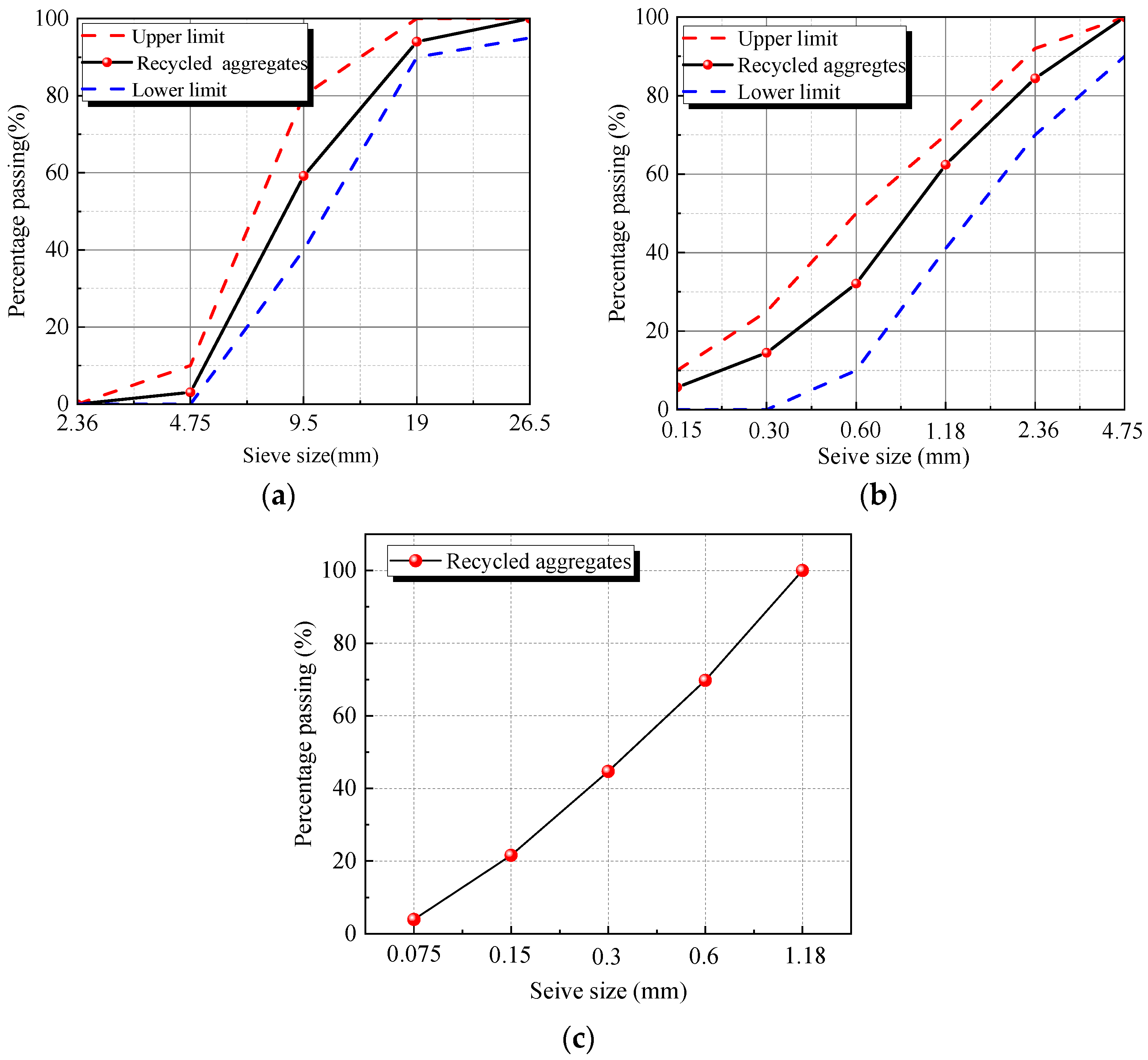
Figure 1. The gradation curves of the (a) 5–20 mm recycled aggregates, (b) 0–5 mm recycled aggregates, (c) 0–1.18 mm recycled aggregates.
Fibers 13 00110 g001
Figure 2. The dimensions and detailed reinforcement of the (a) balanced-reinforced beam, (b) Rare-reinforced beam, (c) Over-reinforced beam.
Fibers 13 00110 g002aFibers 13 00110 g002b
Figure 3. (a) Reinforcement cage, (b) Pouring formwork of for the beam.
Fibers 13 00110 g003
Figure 4. The measuring device and loading diagram.
Fibers 13 00110 g004
Figure 5. The crack width detector.
Fibers 13 00110 g005
Figure 6. Failure modes of the beams.
Fibers 13 00110 g006
Figure 7. Load-maximum crack width curves of the beams: (a) Different concrete strength grades series; (b) Different R-UHTCC layer height series; (c) Different stirrup spacing series; (d) Different reinforcement ratios series.
Fibers 13 00110 g007
Figure 8. Flexural capacities of the composite beams: (a) Different concrete strength grades series; (b) Different R-UHTCC layer heights series; (c) Different stirrup spacings series; (d) Different longitudinal reinforcement ratios.
Fibers 13 00110 g008aFibers 13 00110 g008b
Figure 9. Load-deflection curves of beams: (a) Different concrete strength grades series; (b) Different R-UHTCC layer heights series; (c) Different stirrup spacings series; (d) Different longitudinal reinforcement ratios.
Fibers 13 00110 g009aFibers 13 00110 g009b
Figure 10. Ductility index of the balanced-reinforced beams.
Fibers 13 00110 g010
Figure 11. Load-strain curves of beams: (a) Different concrete strength grades series; (b) Different R-UHTCC layer heights series; (c) Different stirrup spacings series; (d) Different longitudinal reinforcement ratios.
Fibers 13 00110 g011
Figure 12. Transformation diagram of the uncracked section for the composite beam.
Fibers 13 00110 g012
Figure 13. Transformation diagram of the cracked section for the composite beam.
Fibers 13 00110 g013
Figure 14. Comparison between the calculated and experimental stiffness of beams.
Fibers 13 00110 g014
Table 1. Physical and mechanical properties of recycled aggregates.
Particle Size (mm)Apparent
Density (kg/m3)
Bulk Density (kg/m3)Crush Index (%)Water
Absorption (%)
5–20 mm2661123313.674.29
0–5 mm2593134219.977.37
0–1.18 mm2536130918.36.72
Table 2. Properties of polyvinyl alcohol fiber.
Ultimate Tensile Strength (MPa)Length
(mm)
Diameter (mm)Elongation (%)Elastic Modulus (GPa)Linear Density (g/cm3)
160012407.8381.3
Table 3. Physical and mechanical properties of steel bars.
Reinforcement TypeDiameter (mm)Yield Strength (MPa)Tensile Strength (MPa)Elastic Modulus (GPa)
HRB40010462617200
HRB5008559724205
HRB50016554688205
HRB50020580717205
Table 4. The detailed mix proportions of recycled concrete (kg/m3).
Strength GradeCementRecycled Fine
Aggregate
Recycled Coarse
Aggregate
SuperplasticizerWater
C3039064511700215
C5041561912012.08185.2
C7052062511289.52144.4
Table 5. The detailed mix proportions of R-UHTCC (kg/m3).
Strength GradeCementFly AshRecycled Fine
Aggregate
Polyvinyl Alcohol
Fiber
SuperplasticizerWater
C30503.9503.9403.119.50453.5
C50758.9325.2433.719.51.1433.7
C70852.8365.5487.319.54.3365.5
Table 6. Detailed design parameters of each beam.
Beam IdentifierConcrete Strength GradeR-UHTCC Layer Height (mm)Stirrup Spacing (mm)Reinforcement Ratio (%)
C30H1S10R1C301001001.043
C50H1S10R1C501001001.043
C70H1S10R1C701001001.043
C50H2S10R1C502001001.043
C50H3S10R1C503001001.043
C50H1S15R1C501001501.043
C50H1S20R1C501002001.043
C50H1S60R1C501001.043
C50H1S10R0C501001000.258
C50H1S10R3C501001003.681
Table 7. Basic mechanical properties of recycled concrete and R-UHTCC.
Strength GradeRecycled Concrete (MPa)R-UHTCC (MPa)
fcufstfcoEcfcufstfcoEc
C3033.84 [0.068]2.21 [0.055]27.92 [0.058]21,053 [0.007]31.30 [0.034]2.38 [0.082]25.24 [0.024]20,466 [0.039]
C5052.35 [0.035]2.83 [0.031]40.69 [0.048]30,772 [0.045]54.69 [0.049]3.51 [0.005]47.16 [0.042]23,557 [0.085]
C7072.07 [0.008]3.37 [0.024]57.74 [0.059]36,128 [0.041]71.04 [0.013]4.22 [0.082]61.88 [0.046]24,123 [0.046]
Note: the numbers in the brackets [] represent the coefficient of variation for each batch of specimens.
Disclaimer/Publisher’s Note: The statements, opinions and data contained in all publications are solely those of the individual author(s) and contributor(s) and not of MDPI and/or the editor(s). MDPI and/or the editor(s) disclaim responsibility for any injury to people or property resulting from any ideas, methods, instructions or products referred to in the content.