1. Introduction
Li-ion batteries are the primary technology used for energy storage in a variety of applications, ranging from electric vehicles to consumer electronics. The demand for batteries with high energy and power density is increasing due to the automotive industry’s focus on extending the driving range per charge and enabling fast charging capabilities. As a result, significant efforts have been made to enhance the energy and power density of batteries [
1,
2]. Energy density can be improved by using high-capacity, high-voltage cathode active materials (CAMs) or by increasing the areal capacity (loading) of CAMs [
1,
2,
3,
4]. Meanwhile, power density can be enhanced by reducing electrode tortuosity and improving electron and ion transfer processes [
5,
6,
7,
8].
At high areal capacities and charge/discharge rates, battery performance is hindered by both the slow Li-ion transfer through the thick cathodes and the sluggish electron transfer at the cathode–current collector interface [
5,
6,
7,
8,
9]. Several strategies have been employed to improve Li-ion transfer through thick electrodes, including electrode engineering techniques such as freeze tape casting, increasing porosity, and the development of layered cathodes [
10,
11,
12,
13].
Passive layers, such as the Al
2O
3 layer formed on the Al current collector, prevent the dissolution of Al metal in the high potential range (3.0 V–4.5 V) typically used for layered cathode materials (e.g., LiNi
xCo
yMn
1−x−yO
2: NMC) [
14,
15,
16,
17,
18]. Additionally, electrolyte additives (e.g., LiPF
6) contribute to the formation of passive layers, such as AlF
3, on the Al current collector, further protecting it from corrosion in this voltage range [
14,
15,
16,
17,
18]. While these passive layers are effective at preventing Al current collector corrosion under high-voltage conditions, they—especially Al
2O
3—can increase the contact resistance at the interface between the Al current collector and the CAM (e.g., LiFePO
4) [
14,
15,
16,
17,
18]. The increased contact resistance at the current collector–CAM interface, in turn, slows down electron transfer at this interface.
Efforts have been made to reduce contact resistance at the current collector–CAM interface by applying carbon coatings on Al current collectors. Carbon coatings have been shown to improve both rate capability and long-term cyclic stability [
19,
20,
21,
22]. Various carbon materials, including graphene sheets, carbon nanotubes (CNTs), and amorphous carbon, have been tested for this purpose [
19,
20,
21,
22]. Carbon coatings can be deposited using a slurry of carbon materials and polymers in organic solvent (e.g., N-methyl pyrrolidone, NMP) via doctor blade coating [
19,
20,
21,
22]. Carbon coatings can also be made by heating the Al current collectors with CH
4 at 600 °C [
19,
20,
21,
22]. The effect of different carbon coatings on the electrochemical performance of cathodes has been compared, with the order of effectiveness being: graphene sheets > CNTs > activated carbon [
20]. It has been found that “the higher the electronic conductivity of the carbon material, the greater its impact on the electrochemical performance of the battery cell”. It has been found that the electron transfer through the “CAM to carbon to Al current collectors” is faster than the direct electron transfer from the “CAM to the Al current collectors”.
Previous studies have typically involved applying carbon coating to the Al current collector separately, which adds an extra step in cathode production. Making carbon coatings usually requires the inclusion of polymers and organic solvents, such as NMP. Since polymers are insulative, they reduce the electronic conductivity of the coatings compared to the carbon materials alone. Additionally, slurry-based coatings require a drying step and the recovery of toxic solvents, making the process highly energy-intensive. Similarly, high-temperature heating of CH4 and Al current collectors to form a carbon coating is also energy-intensive and does not allow the use of different types of carbon materials.
To date, no research has reported fabricating the carbon coating and cathode layer simultaneously in a single step. Though carbon coatings based on graphene, CNTs, and amorphous carbon have been widely reported, little attention has been given to the effect of an interlayer of continuous, un-sized carbon fibers aligned in one direction (CF interlayer) on Al current collectors. Carbon fiber (CF) is a form of graphite, produced as long continuous fibers from precursor polymer fibers such as polyacrylonitrile. CF has an electronic conductivity ≈ 10
5–10
6 S/m [
23]. Compared to its other carbon counterparts (e.g., CNTs and graphene platelets), CF is generally thicker (≈5 µm). Other carbon materials (e.g., graphene, CNTs, etc.) are small in length (50 nm–1 µm), but CFs are continuous and can be synthesized in the desired lengths (>1000 m).
Most current studies on carbon coatings for current collectors focus on LiFePO
4 (LFP) cathodes due to their low cost, thermal stability, and widespread use in electric vehicle (EV) batteries [
24,
25]. Furthermore, LFP has a very low electronic conductivity (10
−9–10
−10 S/cm) and lithium-ion diffusivity (10
−14–10
−16 cm
2/s), which has also driven carbon coating research aimed at improving the performance of LFP cathodes [
24,
25]. In contrast, studies on carbon coatings for current collectors in layered cathodes, such as LiNi
xCo
yMn
1−x−yO
2, have received less attention, despite these cathodes’ intermediate electronic conductivity (10
−5–10
−6 S/cm) and lithium-ion diffusivity (10
−8–10
−10 cm
2/s) [
26,
27].
In the present work, we investigate how an interlayer of continuous, un-sized carbon fibers aligned in one direction (CF interlayer) on Al current collectors affects the electrochemical performance of NMC811 cathodes. The CF interlayer was incorporated during the fabrication of the cathode layer and without any additional polymer additive or coating formation step. Therefore, the present study removes insulative polymers, additional steps for making carbon coating, and the use of NMP for making carbon coating. Additionally, the CF interlayer can be placed on the current collector during the production of cathode coatings using slot-die or doctor blade coating processes. We anticipate that the inclusion of the CF interlayer will require only minimal modifications to the existing coating equipment.
2. Experimental Section
2.1. CF Interlayer Preparation
A CF interlayer was prepared by forming a very thin layer of long, continuous, unsized carbon fibers (unsized M7 from Hexcel Corp, Stamford, CT, USA) on an Al current collector. The fibers were aligned in a single direction, almost parallel to each other. Care was taken to spread the fibers evenly and minimize stacking, maintaining the CF interlayer thickness close to that of a single carbon fiber (≈5 µm). After placing the carbon fibers on the Al current collector, a cathode slurry was poured over the CF interlayer. A doctor blade was then used to make the cathode coating on this CF interlayer.
2.2. Electrode Fabrication
The cathode slurry was prepared by mixing 90 wt% LiNi0.8Mn0.1Co0.1O2 (NMC811, Targray, Kirkland, QC, Canada) powder, 5 wt% carbon black (Li-100; Denka Black, Chuo-ku, Tokyo, Japan), and 5 wt% PVDF (5130; Solvay, Alpharetta, GA, USA) in NMP. Cathode coatings were coated on Al foil (MTI Corporation) using a doctor blade. The slurry was mixed using Retsch-MM 400 mixture (Retsch, Newtown, PA, USA) for 1 h at a frequency of 20/s. The final solid content of slurry was 55 wt%.
The anode slurry was prepared by combining 92 wt% graphite (SLC 1520T; Superior Graphite, Chicago, IL, USA), 2 wt% carbon black (Imerys, Paris, France; C-NERGY C65), and 6 wt% PVDF (9300; Kureha, Houston, TX, USA) in NMP. The slurry was mixed using a Retsch-MM 400 mixture for 1 h at a frequency of 25/s. The final solid content of slurry was 55 wt%. Anodes were coated using a doctor blade on copper foil. Electrodes were dried at 90 °C overnight.
Electrodes were punched for the coin cell assembly without calendaring. Punched electrodes were further dried overnight in a vacuum oven at 100 °C. Coin cells were assembled inside an argon-filled glovebox. The electrolyte was 1.2 M LiPF6 in 3:7 wt% ethylene carbonate/ethyl methyl carbonate. The cathode areal capacity for rate capability studies was 4.2 mAh/cm2 and was 3.25 mAh/cm2 for long-term cycling studies. The N:P ratio for both rate capability and long-term cycling studies was 1.1.
2.3. Electrochemical Performance Testing
For long-term cycling, 3 formation cycles (C/20 charge and C/20 discharge, 1 C = 200 mA/gNMC) were performed on all cells before subsequent testing, which included 500 cycles at a 1 C charge and 1 C discharge rate. For rate capability evaluation, 3 formation cycles (C/10 charge and C/10 discharge, 1 C = 200 mA/gNMC) were performed. The rate capability tests were performed with a constant charge rate (C/3) and various discharge rates (C/5 to 5 C). Five cycles were performed for each C-rate. All electrochemical performance studies were performed in a voltage window of 3.0 V to 4.2 V. A Maccor potentiostat was used for all electrochemical performance studies.
2.4. Electrochemical Impedance Spectroscopy (EIS) Measurements
EIS measurements were performed on a BioLogic Potentiostat with an alternating current (AC) signal amplitude of 10 mV in the frequency range from 100 kHz to 10 mHz. Full cells, with a graphite anode and an NMC811 cathode with or without a CF interlayer, were used.
2.5. Adhesion Strength Measurements
Adhesion strength was measured using a peel tester (Mecmesin-Friction Peel Tear), with a 100 N module. For performing adhesion strength measurements, 2.0 cm wide strips of cathodes were cut. A piece of 1-inch-wide double-sided tape (3M, Saint Brown, MN, USA) was affixed on the steel plate of the peel tester. The cathode piece was affixed to this double-sided tape by attaching the cathode side to the tape and the current collector side facing up. The affixed cathode was pressed for 1.0 min using a 35-pound weight. Then the metal plate along with the affixed cathode was tightened on the peel tester, followed by adhesion of a 2.0 cm wide single-sided tape to the current collector of the cathode. The single-sided tape was pulled by using a 100 N force module. Three measurements were performed on each sample.
3. Results and Discussion
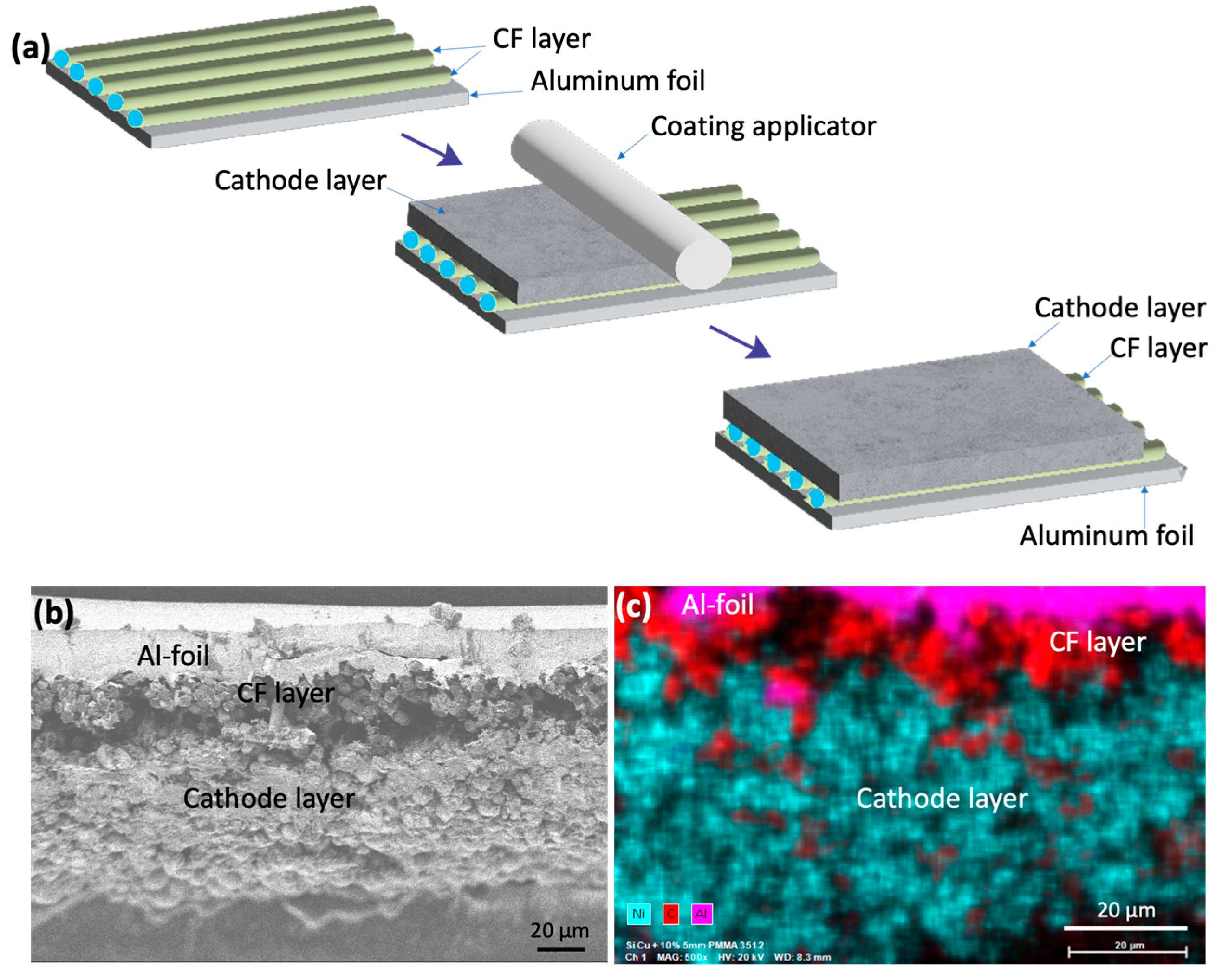
Figure 1 shows the schematic for fabricating NMC811 cathodes with a CF interlayer (
Figure 1a). The CF interlayer was made as thin as possible, typically a single layer (≈5 µm thick made of only one layer of CFs). However, depositing a single layer of CF proved challenging under current experimental conditions. As a result, some areas featured multiple CFs (two to three) stacked together. These stacked CFs are visually apparent during cathode fabrication and in the cross-sectional view of the cathode (
Figure 1b). The scanning electron microscope (SEM) image (
Figure 1b) reveals that the CF interlayer interfaces well with both the CAM layer and the aluminum current collector. This strong interface is expected, as the cathode slurry contains a PVDF polymer, which is known to bind strongly with CF. To further confirm the binding of PVDF with CF, unsized chopped CFs (7–8 mm in length) were dispersed in NMP, both with and without a small amount of PVDF. It was observed that the chopped CFs did not disperse in NMP alone, but readily dispersed when PVDF was added.
Figure 1c shows the EDAX maps of the cross-section of the NMC811 cathode with the CF interlayer, indicating that the CF interlayer is not uniformly thick, but ranges from 5 µm to 10 µm.
To validate our hypothesis that the CF interlayer improves charge transfer at the current collector–CAM interface, we performed electrochemical impedance spectroscopy (EIS) measurements.
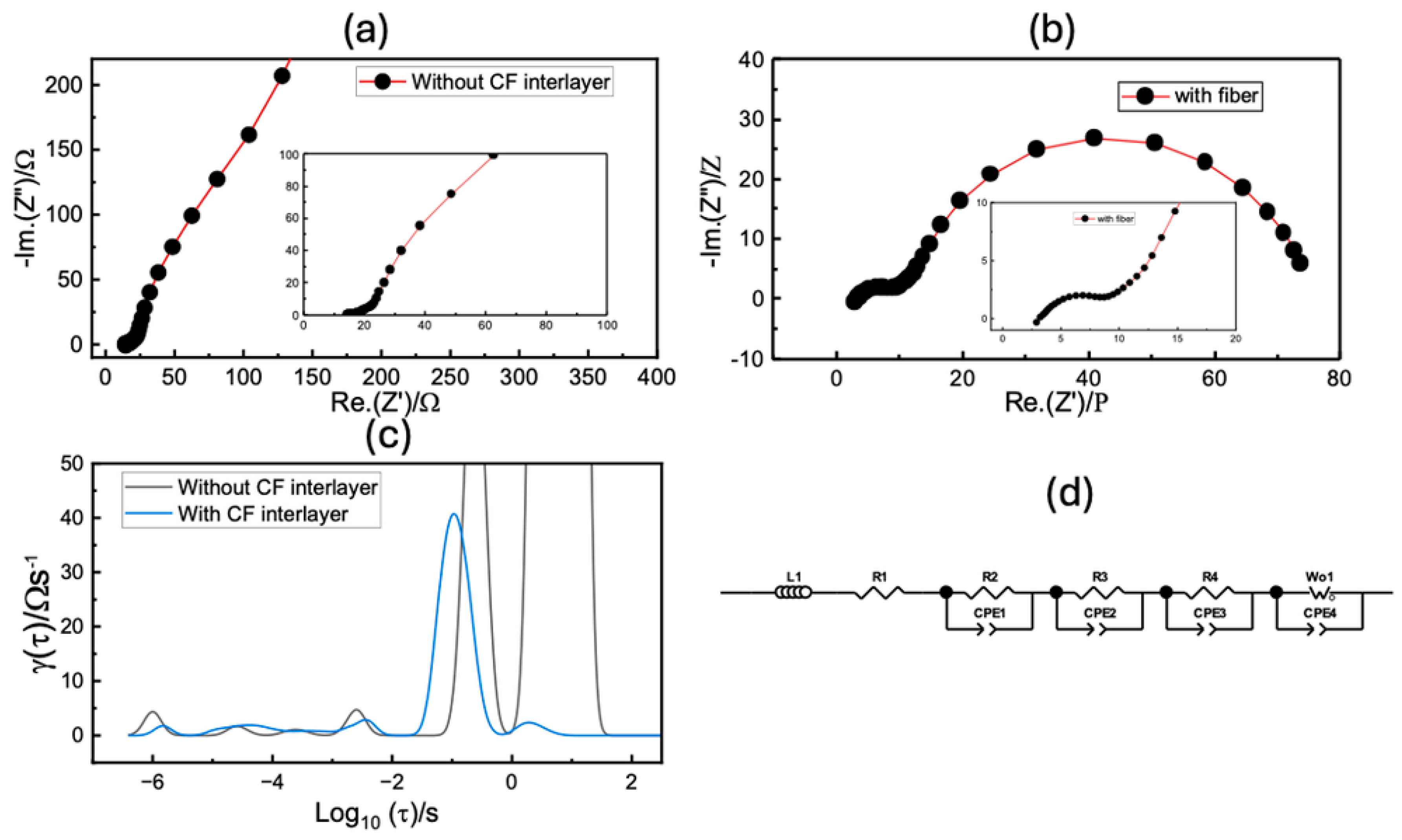
Figure 2 compares the impedance spectra of cells with control cathodes (without the CF interlayer) and cathodes with the CF interlayer, as well as the distribution of relaxation time (
Figure 2c). In
Figure 2a,b, the two cells display very different impedance patterns. The control cathode exhibits much higher resistance than the cathode with the CF interlayer. Both cells show two semicircles and a diffusion peak along with an induction tail. However, the distribution of relaxation time (DRT) reveals more than three electrochemical processes. The equivalent circuit was designed based on the DRT, and further details of the circuit can be found in References [
26,
28,
29]. The individual resistance processes were separated by fitting the impedance spectra with the equivalent circuit, and the resulting data are displayed in
Table 1.
It is evident from
Table 1 that there is a significant difference in the series and interfacial resistances between the cell with the control cathode and the cell with a cathode having CF interlayer. The addition of the CF interlayer likely improves the electronic contact between the active material and the current collector, reducing interfacial resistance. EIS studies show that charge transfer resistance is significantly lower for cells having cathodes with a CF interlayer.
The activation energy of the conductance (
G = 1/R) that is associated with the charge transfer mechanism was derived from the measured charge transfer resistance (R) values at different temperatures. The temperature dependences of the conductance (G) for the cathodes with a CF interlayer and cathodes without a CF interlayer are shown in the Arrhenius plot in
Figure 3 The activation energies were calculated from the best linear fit of the measured values with the Arrhenius equation,
where ‘
E’ is the activation energy,
k is the Boltzmann’s constant, and
G0 is a pre-exponential factor denoting the high-temperature limit of the conductance values [
30].
The activation energy was higher (39.66 kJ/mole) for cells with cathodes with a CF interlayer when compared to that (33.10 kJ/mole) of cells with cathodes without a CF interlayer (
Figure 3). It appears that the CF interlayer facilitates fast electron transfer from the cathode particles to the current collector and vice versa. The improved charge transfer through the carbon intermediates is a known phenomenon and has been investigated before [
19,
20,
21,
22]. The improved electron transfer in turn helps in improving the intercalation-deintercalation of the Li-ions in and out of the cathode layer. It must be noted that for every Li-ion transfer, there should be a corresponding electron transfer; therefore, the electron transfer speed impacts the intercalation speed of Li-ions in and out of cathode particles.
Adhesion strength measurements based on the peel test (details in the Experimental Section) showed that the presence of a CF interlayer does not significantly impact the adhesion strength between the cathode and the current collector (
Figure 3b).
Figure 3c,d show photos of peel tests performed on cathodes without a CF interlayer and with a CF interlayer, respectively. The cathodes with the CF interlayer had an adhesion strength of 45 ± 5 N/m, while those without the CF interlayer had an adhesion strength of 48 ± 5 N/m. The cathode slurry penetrates the spaces between the CF interlayer, allowing the PVDF binder to bind with the Al current collector. As a result, a considerable amount of PVDF binder attaches to the current collector surface, even when the CF interlayer is present. Additionally, adhesion strength tests showed that the CF interlayer remained attached to the cathode, while the current collector was cleanly separated (
Figure 3d). This suggests that the CF interlayer forms a tight bond with the cathode layer, which likely facilitates faster charge transfer from the cathode to the CF interlayer and then to the current collector. Tight bonding between the CF interlayer and the cathode layer has also been revealed by SEM cross-section studies (as explained above in
Figure 1b,c).
Rate capability studies (
Figure 4a) showed that at low C-rates (<1C), the discharge capacities were similar for the cells with cathodes with or without a CF interlayer. However, cells with cathodes with a CF interlayer exhibited higher discharge capacities at higher C-rates (1C, 2C, 3C, and 5C) than those of the cells without a CF interlayer (
Figure 4a). The charge/discharge profiles at different C-rates are shown in
Figure 4b,c. Discharge capacities for cells with the CF interlayer were 168, 137, 90, and 42 mAh/g at 1C, 2C, 3C, and 5C, respectively. For cells without the CF interlayer, the discharge capacities were 152, 100, 48, and 15 mAh/g at the same rates. At low C-rates (<1C), the discharge capacities and voltage plateaus were similar for both sets of cells, as expected, since the current is too low to show any significant polarization differences. However, at higher C-rates (>1C), cells with the CF interlayer exhibited significantly higher discharge capacities, and the voltage profiles clearly reflected this difference. Additionally, at higher C-rates (>1C), the polarization of both charge and discharge plateaus was less for cells with the CF interlayer compared to those of the cells having no CF interlayer. This indicates that the CF interlayer effectively reduces polarization, suggesting improved electron transport from the active material to the current collector, which in turn helps in improving discharge capacities at higher C-rates. Long-term cycling studies were conducted at 1C/−1C charge/discharge rates. These studies demonstrated that the cyclic stability of cells with or without the CF interlayer was similar, with both showing comparable capacity retention after 500 cycles (
Figure 4d). An initial drop (up to ≈ 30 cycles) in capacity during long-term cyclic stability studies was observed due to incomplete wetting of electrodes by the electrolyte. The capacity of cells recovered by the 50th cycle. Up to the 250th cycle, cells having cathodes with a CF interlayer had slightly higher capacities than those of the cells having cathodes with no CF interlayer. From the 250th cycle to the 500th cycle, a slightly faster loss of capacity was observed for cells having cathodes with a CF interlayer. We assume that this may have resulted from the delamination of some fibers from the current collector, resulting in an increased resistance after cycling. Follow-up studies are in progress to understand the cyclic stability of cells at higher C-rates (≥2C), and to understand any changes in the cathode–current collector interface after cycling.
4. Conclusions
The effect of an interlayer of continuous, un-sized carbon fibers aligned in one direction (CF interlayer) between the Al current collector and CAM layer has been investigated. The study found that the CF interlayer reduces the contact resistance at the current collector and cathode interface, enhancing charge transfer at this interface. This improvement leads to enhanced rate capability and discharge capacities at higher C-rates, although the impact is less visible at lower C-rates. The CF interlayer, being directionally aligned and continuous, can enhance electron transport in pouch cells, where electrons flow through tabs attached to one end of the current collector. Importantly, introducing the CF interlayer during cathode layer fabrication eliminates the need for an additional carbon coating step on the current collector, streamlining the electrode production process. Conventional carbon coatings typically require the use of insulative polymers, which reduce their electronic conductivity. In contrast, the CF interlayer does not require such polymers, maintaining higher conductivity. Additionally, CFs are significantly less expensive (≈USD30/kg) compared to CNTs (≈USD150/kg), which could further reduce the manufacturing costs of carbon-coated current collectors. Though, we only investigated the effect of CF interlayers on NMC811 cathodes, we anticipate that CF interlayers will show a similar effect when investigated in other cathode materials such as LFP and LiNi0.5Mn1.5O4 (LMNO). We envisage that this work will not only be useful for improving the performance of cathodes but can also be employed in developing Janus separators or electrolytes in lithium sulfur batteries.


 ,
, 


