Article

Constitutive Model for Plain and Steel-Fibre-Reinforced Lightweight Aggregate Concrete Under Direct Tension and Pull-Out

Department of Engineering and Construction, School of Architecture, Computing and Engineering, University of East London, Docklands Campus, London E16 2RD, UK
*
Author to whom correspondence should be addressed.
Fibers 2025, 13(7), 84; https://doi.org/10.3390/fib13070084
Submission received: 21 March 2025 / Revised: 28 April 2025 / Accepted: 12 June 2025 / Published: 23 June 2025

Abstract

In the present study, a programme of experimental investigations was carried out to examine the direct uniaxial tensile (and pull-out) behaviour of plain and fibre-reinforced lightweight aggregate concrete. The lightweight aggregates were recycled from fly ash waste, also known as Pulverised Fuel Ash (PFA), which is a by-product of coal-fired electricity power stations. Steel fibres were used with different aspect ratios and hooked ends with single, double and triple bends corresponding to 3D, 4D and 5D types of DRAMIX steel fibres, respectively. Key parameters such as the concrete compressive strength flck, fibre volume fraction Vf, number of bends nb, embedded length LE and inclination angle ϴf were considered. The fibres were added at volume fractions Vf of 1% and 2% to cover the practical range, and a direct tensile test was carried out using a purpose-built pull-out test developed as part of the present study. Thus, the tensile mechanical properties were established, and a generic constitutive tensile stress–crack width σ-ω model for both plain and fibrous lightweight concrete was created and validated against experimental data from the present study and from previous research found in the literature (including RILEM uniaxial tests) involving different types of lightweight aggregates, concrete strengths and steel fibres. It was concluded that the higher the number of bends nb and the higher the volume fraction Vf and concrete strength flck, the stronger the fibre–matrix interfacial bond and thus the more pronounced the enhancement provided by the fibres to the uniaxial tensile residual strength and ductility in the form of work and fracture energy. A fibre optimisation study was also carried out, and design recommendations are provided.

1. Background Review

1.1. Lightweight Aggregate Concrete

Recently, there has been a rapid growth in concrete technology that is particularly directed towards sustainability and upgrading the strength-to-weight ratio [1]. Achieving the latter results in a reduction in the building mass, which leads to savings in materials, construction time and—crucially—a reduction in costs and adverse effects of carbon emissions (including in the transportation of fewer materials). Therefore, the use of structural lightweight aggregate concrete (LWAC) as a replacement to the conventional heavier normal weight concrete (NWC) counterpart helps achieve such goals. In addition, the lightweight aggregate used in this work is made from recycled waste and thus offers the advantage of a further reduction in CO2 emissions, and it is an alternative to depleting quarried natural resources [2]. Recycled aggregates are made from fly ash waste (commonly known as LYTAG), which is a by-product of coal-fired electricity power stations [3]. Fly ash, also termed Pulverised Fuel Ash (PFA), is ash resulting from the burning of pulverised coal in these power stations. Several studies support the environmental benefits provided by this PFA-based material and its effectiveness in reducing carbon emissions [4]. Additionally, it should be noted that LWAC brings other advantages such as increased thermal insulation, noise absorption and fire resistance [5,6]. Thus, the use of lightweight concrete can allow for taller and longer span structures and is also beneficial in situations when a reduction in inertial loads is needed, such as in seismic zones [7,8,9,10]. Nonetheless, despite these benefits, some disadvantages have been highlighted with the use of LWAC. One of the key shortcomings is the increased brittleness of lightweight concrete in comparison to its normal weight counterpart, which is likely due to the porous concrete matrix and its poor aggregate interlock mechanism. This leads to a complete absence of the strain softening mechanism post-cracking [2]. Therefore, for plain LWAC, instantaneous failure is observed both in compression and tension at the material level once peak stress is reached. Similarly, a drastic reduction in shear capacity, excessive deflection and cracking due to the lower modulus of elasticity is expected at the structural level [11,12,13,14]. Despite the fact that modern structural LWAC has been available for over several decades, its mechanical properties have not been comprehensively researched, and the material and structural equations defining its behaviour have been traditionally adapted from dated studies on NWC [12,14,15,16,17,18].

1.2. Steel Fibres

To address the increased brittleness of LWAC, steel fibre reinforcement has emerged as a potential solution whose effectiveness has been proven in increasing the ductility of other fibrous composites in the past [19,20,21,22,23]. This is because one of the key benefits to steel fibres is enhancement to ductility. Their key advantage over conventional bar reinforcement is the reduction in construction time as they can conveniently be added to the concrete ready mix delivered, hence leading to economic and environmental benefits. Steel-fibre-reinforced concrete (SFRC) is also particularly useful for smaller cross-sectional elements and for sprayed concrete, e.g., shotcrete, which is commonly used in tunnel lining. Another potential method is to relax the shear reinforcement spacing at beam ends [24] and in critical elements in seismic-resistant design, such as beam-column joints [21], which can get congested with conventional bar reinforcement, leading to practical construction difficulties. Hooked-end steel fibres are the most commonly used type and are usually made by cutting steel wire into short lengths and then cold-drawing them to create a hook shape at one end. This type of steel fibre is mainly used in structural applications due to its improved bond properties with concrete (compared to straight fibres without end hooks). The bond can be further enhanced by increasing the number of end hooks. The present study examines the performance of single and multiple end hook arrangements. Straight steel fibres, on the other hand, have a smooth surface that reduces friction (and bond with concrete as a consequence). They are usually used in thin concrete structures such as precast concrete panels and overlays, and in applications with less demanding structural performance.
Although somewhat limited, research studies on fibrous lightweight concrete have been reported for several years [25]. However, at present, there are hardly any international standards specific to steel-fibre-reinforced lightweight concrete (SFRLC), with current guidelines usually being adapted from fibrous normal weight concrete (SFRC). The practical application of steel fibre reinforcement in lightweight concrete is still in its infancy, and it is largely carried out at the structural level only in the form of case studies that largely involve lightweight aggregates (such as pumice stone and oil palm aggregates) different to the ones investigated in the present research work [22,23,26,27,28]. The recycled PFA-based aggregates used in this study are well established for structural use by the construction industry, so they represent a good benchmark to test the addition of fibres, meaning that the ensuing findings and recommendations will be useful to current practice. It should also be borne in mind that coal-fired power generation remains the largest contributor of energy in the world [29]; even with the decommissioning of coal plants, there is still a large amount of historical waste. Therefore, the present comprehensive study on fibrous recycled PFA-based lightweight aggregate concrete is particularly beneficial in providing sustainable design solutions for the rapidly developing fibrous concrete technology. The present study is part of a large experimental programme which examined the structural behaviour of steel-fibre-reinforced recycled PFA-based lightweight concrete at both the material and structural levels [30]. The compression structural responses of SFRLC were examined in an earlier publication [31]. The present article is focused on the series of tests that were carried out to investigate the uniaxial tensile and pull-out behaviour of lightweight concrete reinforced with different hooked-end steel fibres at fibre volume fractions Vf of 1% and 2%.

1.3. Tensile Behaviour and Limitations of Existing Research

Under tensile loading, as the principal tensile stress applied exceeds the ultimate tensile resistance of plain concrete, microcracks start to form and morph into a single larger macrocrack, which eventually leads to concrete failing in tension, thus releasing the stored energy of the system [32]. When fibres are added, a crack-arresting action takes place once cracks have formed, and then fibres create a bridge between the ends of the crack to resist its extension. However, as the principal tensile stress grows, and due to sliding friction, the fibres may end up being pulled out or ruptured depending on the number of fibres crossing the crack (which, provided that a good mixing process is used, usually correlates with the fibre volume fraction Vf) and the fibre-matrix interfacial bond strength. The latter is largely governed by the geometry of fibre, its tensile strength, mechanical anchorage, embedment length, inclination angle and concrete strength. These factors govern the post-crack behaviour of fibrous concrete. Researchers such as Löfgren [33] and Lee et al. [34] detailed this behaviour for fibrous normal weight concrete, which benefits from the combined effect of fibre reinforcement and the residual effect of aggregate interlock mechanism once crack develops. Given that the aggregate interlock mechanism is expected to be negligible for lightweight concrete, this effect might be different for fibrous lightweight concrete in the post-cracking phase.
Indirect tensile tests to investigate the flexural tensile behaviour of fibrous concrete can be found in the literature [7,19,26,35,36,37,38]. It is established that the addition of steel fibres upgrades the flexural behaviour of lightweight concrete. However, the uniaxial tensile behaviour of fibrous lightweight concrete has not been thoroughly investigated to establish analytical models. This important aspect is addressed in the present research work because, unlike flexural testing, direct uniaxial tensile testing offers the ideal results required to understand the tensile pre- and post-cracking behaviour of concrete and the interaction of LWAC with fibres. Currently, limited comprehensive studies were found in the literature that are focused on the investigation of the uniaxial tensile stress–strain (σ-ε) or stress–crack width (σ-ω) behaviour and pull-out behaviour of SFRLC. Amongst all the available research examined, it seems that only Grabois et al. [23] and Mo et al. [39] carried out direct uniaxial tensile tests on lightweight concrete using the dog bone test [40] and the RILEM TC 162-TDF uniaxial test [41], respectively. They reported an increase in uniaxial tensile residual strength with hooked-end steel fibre reinforcement with Vf ≤ 0.5% and Vf < 1% compared to plain LWAC, respectively. Grabois et al. [23] showed a stress–strain relationship, while Mo et al. [39] only estimated the tensile strength. Moreover, there seems to be a lack of thorough investigations on the pull-out tensile behaviour of fibrous PFA-based lightweight aggregate concrete, especially with modern multi-bend fibres like the ones used in the present study.
Therefore, the present research work aims to offer more clarity on and a greater understanding of the uniaxial tensile and pull-out behaviour of steel-fibre-reinforced lightweight concrete and presents valuable additional experimental data to enrich the current available literature. This study involved determining the tensile properties, including tensile σ-ω constitutive models for SFRLC, the fracture energy Gf and bond strength. It also led to the development of a fibre optimisation study based on different hooked-end steel fibre types, geometries and contents and different compressive strengths of plain lightweight concrete.

2. Experimental Procedure

The mixing process, materials, grading, vibration, curing and specimen preparation process were all detailed in a preceding paper, which was focused on the compression behaviour of SFRLC [31] as part of a comprehensive experimental research programme [30]. For the sake of completeness and to avoid repetition, only new data are presented in this study.

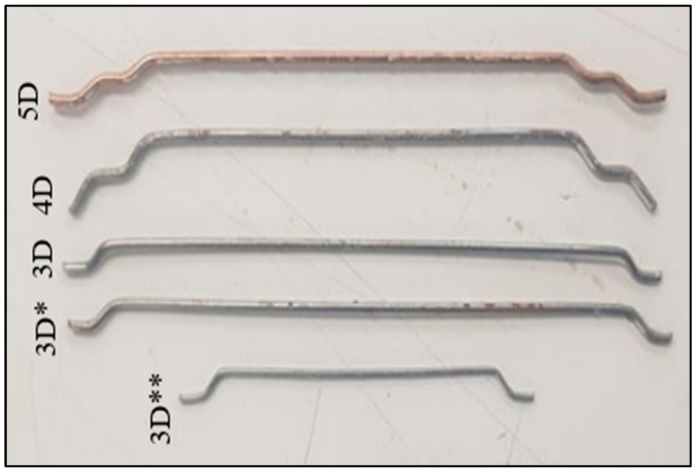
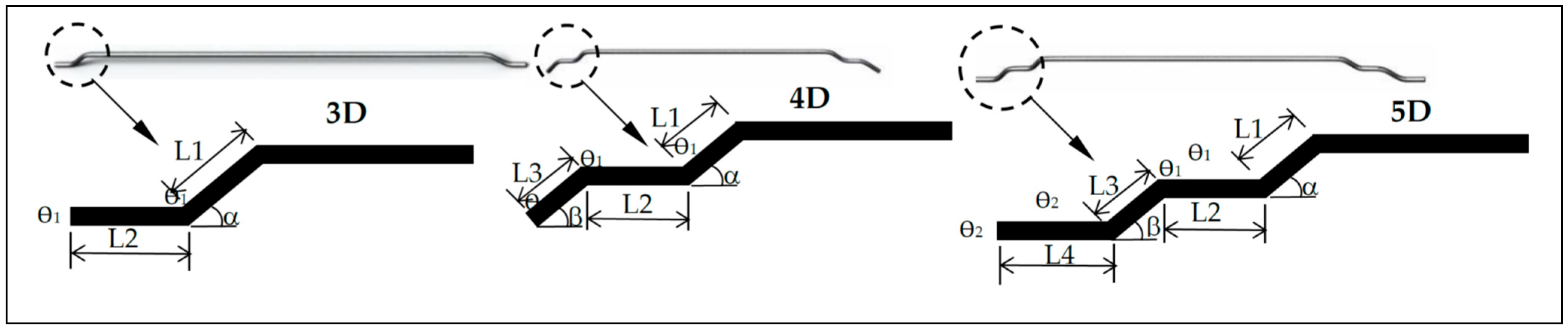
2.1. Material Properties

The chemical and geometrical properties of cement, natural sand and PFA-based coarse aggregates used in the experiments are detailed elsewhere [30,31].
Recycled sintered pulverised fly ash aggregates were used as the coarse aggregates for the lightweight concrete in the present experimental study. Fly ash is a by-product of coal-fired electricity power stations [3]. The aggregates (4–14 mm) are brown, roughly spherical with a honeycomb structure of interconnected voids. They have a specific gravity of about 1.8 and a water absorption capacity of up to 15%. Natural sharp sand with a maximum aggregate size of 4.75 mm was used as the fine aggregate of the concrete. In the present study, Dramix hooked-end (single-bend) 3D fibres with different aspect ratios were incorporated as reinforcement for the pull-out specimens. The fibres tested in this work are shown in Figure 1, while their geometrical properties, which were adapted from Abdallah et al. [42,43], are shown in Table 1. A schematic representation of the parameters shown in Table 1 is depicted in Figure 2. It should be noted that hooked-end 3D fibres were regarded as the control fibres during the experimental programme. The rest of the fibres were used in order to evaluate the effects of different fibre geometries, bends, lengths and diameters on the behaviour of lightweight concrete.

2.2. Properties of Mixes

In addition to the 4 mixes cast in the preceding study on compressive behaviour [30,31], mixes 1-3D* and 1-3D** were added with fibres 3D* and 3D**, respectively (as summarised in Table 2).

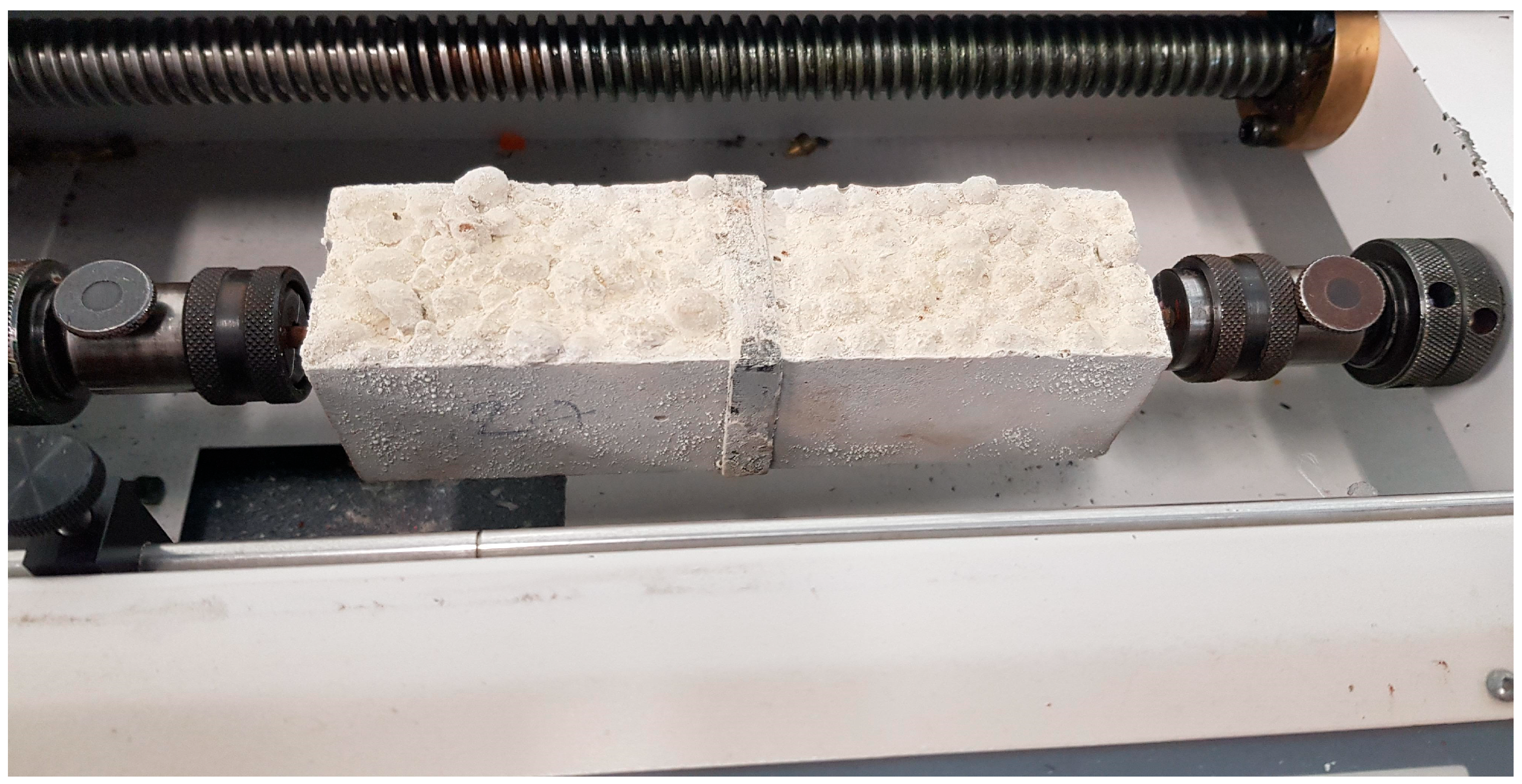
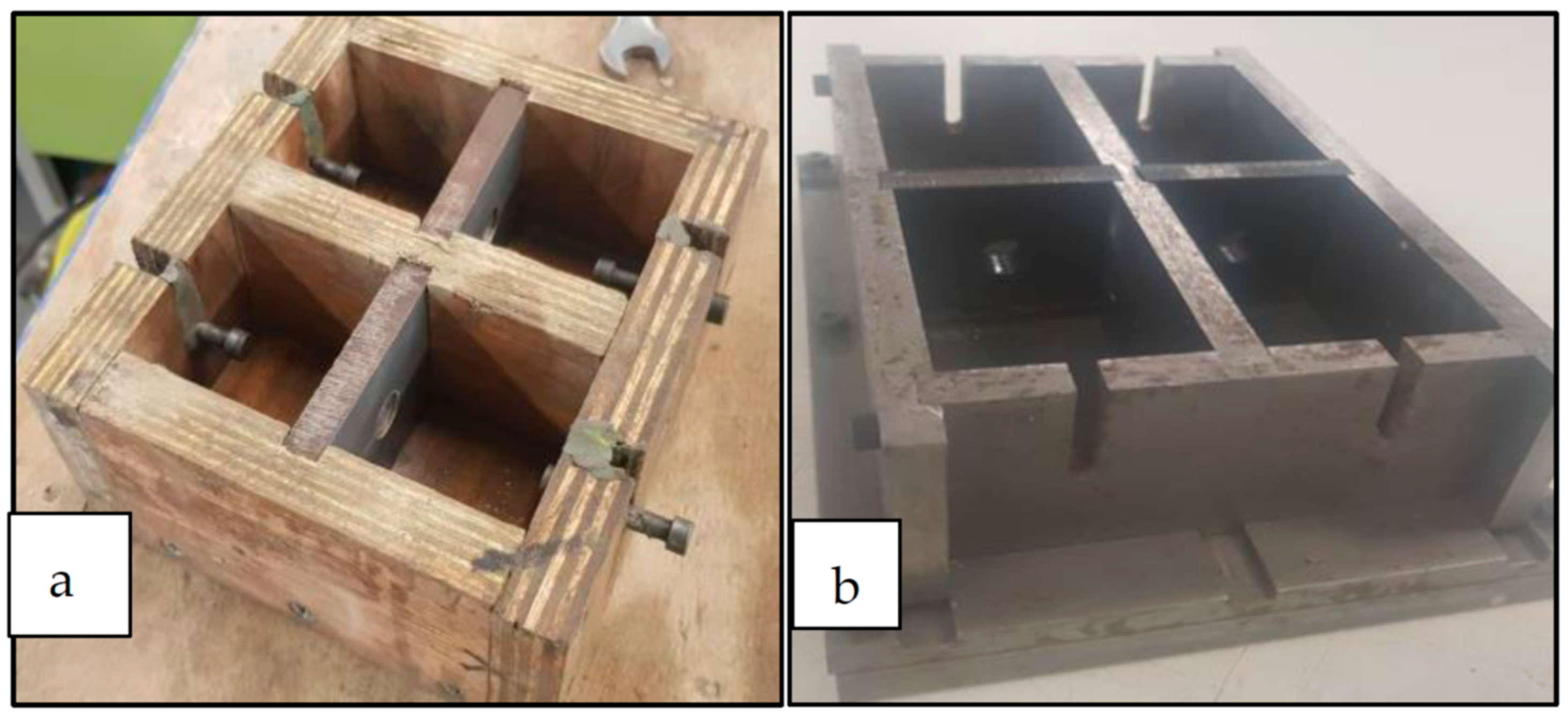
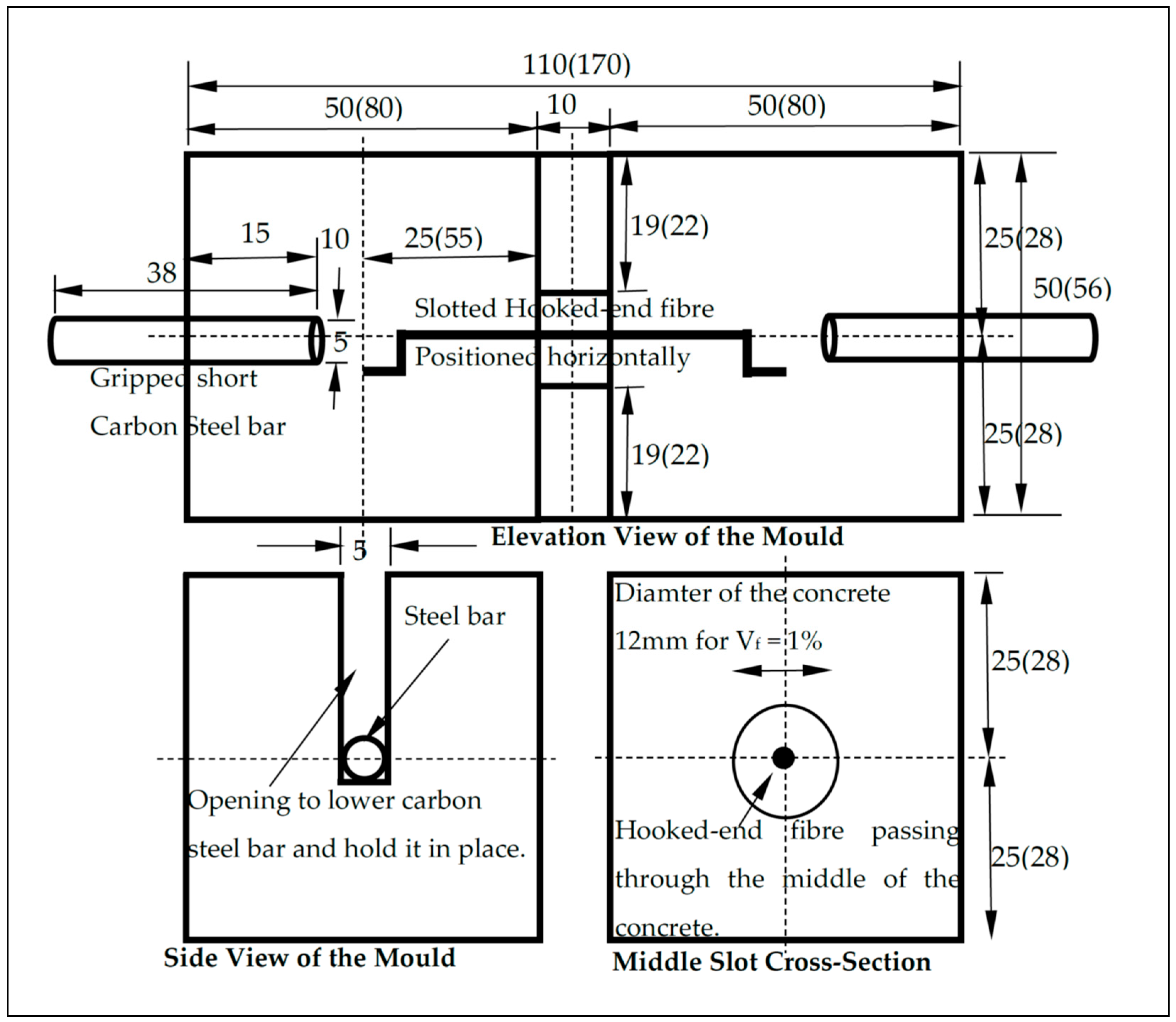
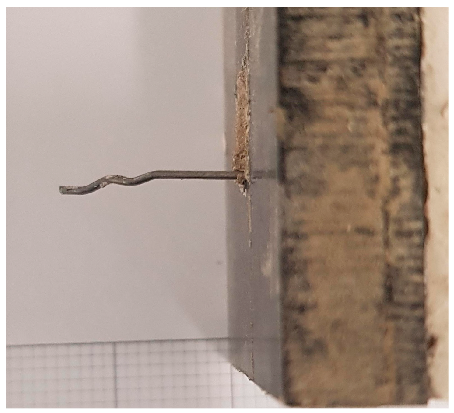
2.3. Test Method for Pull-Out Test

In this section, the details of the design and method of uniaxial tensile pull-out tests on notched prisms are provided. Uniaxial compression cube and cylinder tests with their setups and instrumentations are detailed in an accompanying paper [30,31]. For the pull-out tests, each mix included two repeated notched prism specimens per volume fraction Vf dosage. Building on the previous experimental study by Robins et al. [45], a direct uniaxial tensile pull-out test was designed in the present study, which can be used for both plain and fibrous concrete. The aim was to investigate the effect of the embedded fibres on the uniaxial tensile stress–crack width response of lightweight concrete. The main difference between the test setup proposed in this study and the one by Robins et al. [45] is that for the latter, the steel fibre is embedded in concrete on one end and in a high strength mortar on the other end to grip the fibres and practically prevent their movement on that side, while the fibre in the test setup proposed in this study is embedded in the lightweight concrete matrix on both ends. Hence, Robins et al.’s test [45] is practically similar to the conventional single fibre pull-out test shown in other studies [42,46,47,48].
The designed uniaxial tensile pull-out test adopted in this work (depicted in Figure 3) carries several advantages. First, it provides, to a large extent, a truer representation of the behaviour of steel fibres bridging a crack in a real structural element as compared to the classic pull-out tests explained earlier since fibres are completely embedded in lightweight concrete, while the crack is not predefined but induced by a reduced section (notch) spanning 10 mm in the middle of the specimen. The reason for designing this notch is to allow the continuity of lightweight concrete constituents of the specimen (sand, PFA-based aggregates and cement) through the notch at which breakage is ensured. Also, the notch allows for the introduction of the embedment length LE as a variable and enables the specimen to be monitored in the middle section in terms of load–slip behaviour. Since the crack is not predefined, it was possible to derive the peak tensile cracking load of LWAC and SFRLC when their behaviour was elastic. Secondly, by taking into consideration Vf in the effective area of the cylinder around the embedded fibre, this test can be regarded as both a fibre pull-out test and a uniaxial tensile test. Similarly to the previous experimental study by Robins et al. [45], the effective area of the notched cylinder through which the fibre is embedded was determined using numerical and statistical models, which depend mainly on fibre geometry and fibre volume fraction [49,50,51]. Therefore, the diameter of the notch was calculated to be 12 mm and corresponds to Vf = 1% for DRAMIX hooked-end fibres of df = 0.9 mm (3D, 4D and 5D). It should be noted that to test the concrete for Vf = 2%, simply another fibre was added. The fibre spacing was equal in the notch.
Based on the concrete fibre–matrix interfacial properties which are directly affected by the densification of the matrix and the water/cement (w/c) ratio of concrete (which influence the compressive strength), fibre content Vf, aspect ratio af, mechanical anchorage (number of bends or hooks), embedment length LE, orientation angle, dispersion and tensile strength [45,48,52,53], the stress–crack width relationship was derived. The aforementioned factors govern the bond-slip behaviour between concrete and fibres, which in turn influences the tensile behaviour both at the material and structural levels of SFRLC. Hence, the evaluation of the results of this test explicitly enables the prediction of the behaviour of SFRLC members, such as beams and slabs. It should be noted that 2 moulds with different dimensions were designed to test 2 different types of pull-out notched prism specimens for each mix (shown in Figure 4). The pull-out notched prism specimens were produced using both moulds A and B.
Each mould contained 2 identical chambers. The differences in dimensions between moulds A and B are shown in Figure 5. The reason behind testing 2 different types of notched prisms in the pull-out test was to ensure the development of an accurate and realistic stress–crack width relationship of fibrous lightweight concrete independent of the size effects of the specimen used, and thus, it can be applied to any structural member. Preliminary trials showed that both moulds yielded similar results for identical specimens in terms of the pull-out load–slip behaviour and failure patterns. Therefore, the stress–crack width relationship derived based on these tests can be applied directly to FE models unlike the more common stress–strain relationship, which usually requires calibration or the study of the structural characteristic length lcs, which is used to derive strain ε with ε = ω/lcs. To prepare the pull-out specimen before casting, the fibre was positioned at the notch for the chosen LE and the required inclination angle to the load, using fixed fine suspended cables mechanically attached to the fibre. These were removed once concrete was cast to avoid any potential interference with the results.
During the pull-out test photographed in Figure 3, as the 2 short rigid carbon steel bars (embedded at the ends of the specimen) were being pulled in opposite directions using machine grips, the cylindrical concrete volume through which the fibre was embedded became subjected to pure unidirectional tension. The embedded carbon steel bars had enlarged ends and were further prevented from potential slip with steel washers attached to their heads. Although possible slip of small steel bars might occur before concrete cracking, both concrete blocks embedding the two hooked ends of the fibre were assumed to be rigid following concrete cracking. Since the bond of the carbon steel bar with the lightweight concrete matrix is higher than that of hooked-end steel fibres, the pull-out response of the fibrous lightweight concrete specimen was designed to only occur along the fibre and the surrounding concrete. These assumptions were found to be correct, as shown in the Results Section. The tensile machine was calibrated and fitted with a sensitive displacement transducer capable of accurately measuring the slip once the crack was initiated. The pull-out specimen was carefully placed in the tensile testing machine with a maximum load cell capacity of 20 kN, where the two carbon steel bars from each end were securely gripped in a way to disallow any superfluous slip. While one end was fixed, the other end was gradually pulled in tension at a displacement-controlled loading rate of 1 mm/min with 2 readings recorded every 1 s.
Cao and Yu [54] found that the embedment length plays a dominant role in the behaviour of fibre pull-out as a short embedment length at an inclination angle of 30° degrees for ultra-high-performance concrete caused matrix fracture failure. Robins et al. [45] also suggested that unless the embedment length is higher than the hooked-end length, the pull-out load is reduced. Abdallah et al. [48] concluded that the embedment length had no influence on the pull-out strength but merely increased the slip and ductility. Hence, it is important to investigate the effect of LE on SFRLC. For instance, although a 30 mm embedment length maximises the frictional fibre pull-out for 3D fibres used (df = 60 mm), it is thought that an embedment length LE = 30 mm can lead to an unrealistically favourable case of uniaxial tensile tests, as in the cracking of a real structural member can manifest anywhere along the fibre and is more likely to occur at a shorter embedment length. Thus, the embedment length was initially fixed at 30 mm, 20 mm and 10 mm for different specimens based on a crack that is expected to take place in the middle of the 10 mm notch.
An angle of 0° to the load is considered as the most unfavourable in a hooked-end fibre pull-out test due to the lowest possible frictional resistance and the shortest required length for fibre straightening (only hooks will be straightened) before being pulled out. Consequently, the fibre stress developed during pull-out will be lower than the maximum stress capacity of the fibre. If the angle is too large, concrete matrix fracture failure could also develop due to matrix spalling caused by the snubbing effect along the bent part of the steel fibre [54]. Depending on the fibre tensile strength, in theory, as the angle to the load is increased, frictional resistance is increased, which results in an increase in the uniaxial tensile strength of SFRLC until the maximum tensile strength of the fibre is reached, leading to rupture, so long as the concrete matrix does not break due to the concentrated normal force from the fibre and given that the embedment length does not reduce to the point where the hook is not well bonded. Recent research on ultra-high-strength concrete conducted by Cao and Yu [54] revealed that the inclination angle for the maximum pull-out load can be around 20–30° to the horizontal (and 10–20° for Robins et al. [45]) provided that the fibre tensile strength is high enough to prevent fibre rupture and the matrix is strong and dense enough to prevent matrix fracture. Since the lightweight concrete used is not as dense as ultra-high-strength or normal weight concrete, since LWAC is known to have air pores, and for design purposes [55], it was decided that an angle of 0° was to be adopted as the base for design in the pull-out tests, while a few specimens with other angles were tested for completeness.
Finally, the aspect ratio which is defined as Lf/df can also impact the pull-out behaviour. It was found that the longer the fibre, the more efficient the crack bridging [42]. Based on all of the above observations, the testing programme comprised an extensive fibre pull-out investigation which considered the following parameters: Vf = 0, 1 and 2%; flck = 30, 35 and 40 MPa; Lf/df = 65 and 80; df = 0.55, 0.75 and 0.9 mm; Lf = 35 and 60 mm; number of fibre hooks or bends nb = 1(3D), 2(4D) and 3(5D); and inclination angles of 20° and 45°. Also, 3D and 5D fibres with the hooks cut off were tested to check the viability of mixing straight fibres of different tensile strengths with lightweight concrete and to quantify the contribution of the hooks on the pull-out behaviour.

3. Results and Discussion

The workability, density and uniaxial compressive cube strength results were detailed in an accompanying paper for mixes 1-3D, 1-4D, 2 and 3 [30,31]. The additional mixes 1-3D* and 1-3D** showed similar workability, density properties and compressive strength results to mix 1-3D, and these results are summarised in Table 3 (data for convenience mixes 1–3 are also included). To avoid repetition, the interpretation of the results and trends can be directly adopted from accompanying studies [30,31]. In summary, it was found that the mechanical properties were improved with the addition of fibres, and the density was largely unaffected, which is important for LWAC applications. On the other hand, the workability was significantly reduced with the addition of more than a 2% volume fraction of fibres. This further emphasises that for fibrous mixes, the fibre dosage should not exceed Vf = 1.5–2% based on workability challenges if no superplasticisers or water-reducing agents are used. It also appears that the mixes having fibres with more extensive hooks held the slump together more tightly, which led to lower slump values than the mixes having fibres with less extensive hooks. It should be noted that mix 1-3D** with the shortest fibres 3D** exhibited the highest slumps and highest densities amongst all mixes.

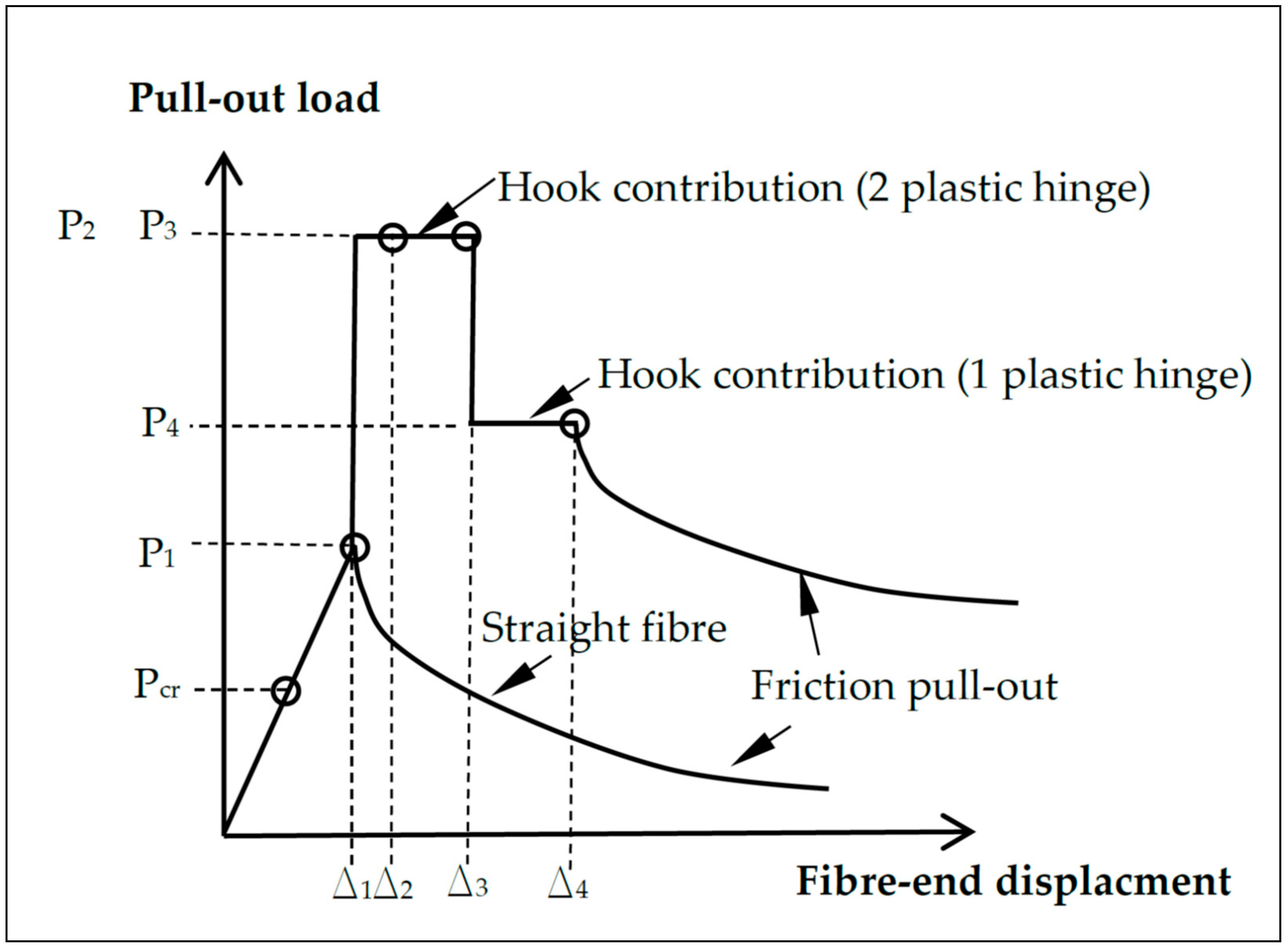
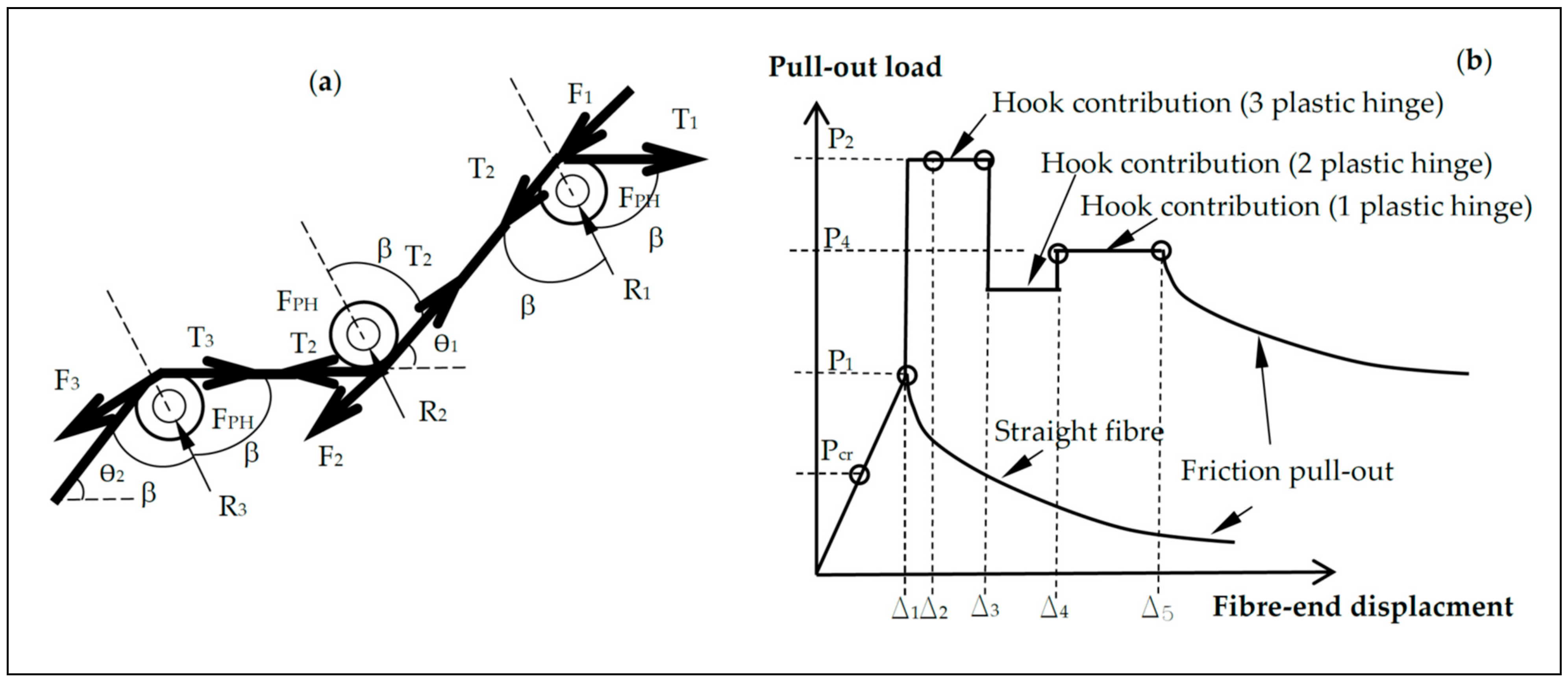
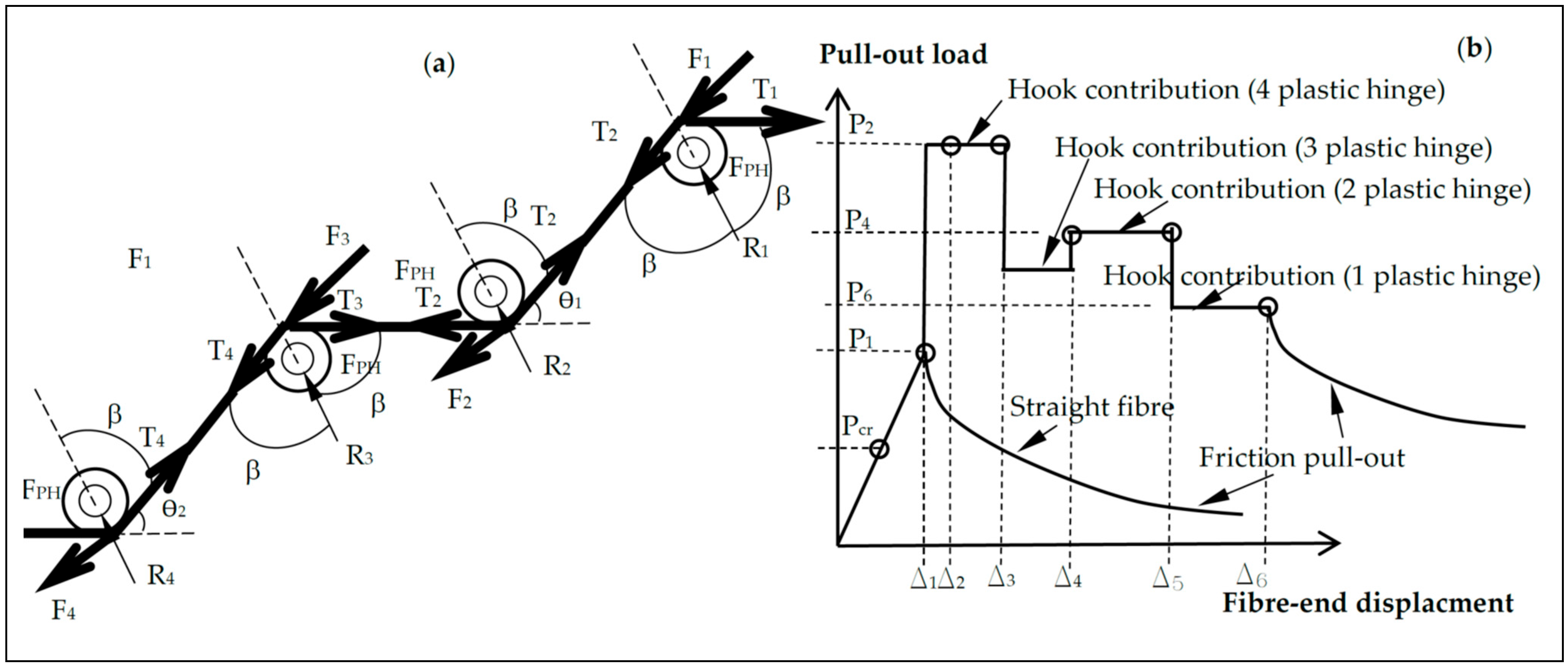
3.1. Pull-Out Load–Slip Behaviour

A fully straightened hooked-end 3D fibre photographed at the end of testing is shown in Figure 6. It can be seen that the effective cylinder through which the fibre was embedded contained aggregates as well as cement and sand at the notch through which the fibre was centred. This proves that the mould used and the testing design adopted were adequate at mimicking the realistic behaviour of SFRLC at the crack.
Figure 7 depicts the pull-out load–slip behaviour of some key specimens tested (with the salient features summarised in Table 4). Overall, the behaviour of the SFRLC specimens in the pull-out test can be summarised in the following stages: Initially, an elastic stage takes place until the point of cracking. This point approximately coincides with the load at which plain concrete would fail in uniaxial tension and is roughly the case for all the specimens of similar concrete grade tested regardless of the type of fibre or fibre volume fraction. This shows that fibres have an insignificant effect on the elastic uniaxial tensile behaviour of SFRLC and only become active once the concrete cracks. In the absence of any innate tension stiffening mechanism, such as in the case of brittle plain lightweight concrete, a sudden drop in load to 0 is seen (which is the case for the plain concrete specimen, i.e., Vf = 0%, shown in Figure 7).
With the incorporation of steel fibres, however, the plain lightweight concrete peak tensile strength where the principal crack is fully formed is followed by a drop and then an increase in load. This behaviour largely agrees with that observed in the uniaxial tensile tests on SFRC carried out by Barragán et al. [56] and Abdallah et al. [42] and the pull-out tests performed by Robins et al. [45]. This marks the fibre bridging phase, which is initially characterised by an elastic behaviour followed by fibre debonding where a gradual loss of the frictional bond between the fibre and matrix is seen. Afterwards, the activation of mechanical hooking is initiated. This behaviour was also reported by Qi et al. [55]. This results in an increase in the peak residual tensile load due to fibre reinforcement only. This load is mainly affected by concrete strength, fibre mechanical anchorage (number of hooks), fibre diameter, fibre tensile strength and inclination angle. Also, if the embedment length is not adequate to cater for hook straightening and thus the mobilisation of the maximum possible fibre stress for the composite, the peak load can be drastically reduced due to the possibility of matrix cracking at hook ends. Maintaining this load solely relies on the bond between the steel fibres and concrete. During this stage, the fibre undergoes plastic deformation at hooks, and plastic hinges are developed. The maximum number of plastic hinges at the maximum load become active (two for 3D, three for 4D and four for 5D). This stage is followed by stress relaxation, which is characterised by full hook straightening and the deactivation of the plastic hinges. Finally, frictional fibre–matrix pull-out occurs, and the test ends with the fibre being completely pulled out.

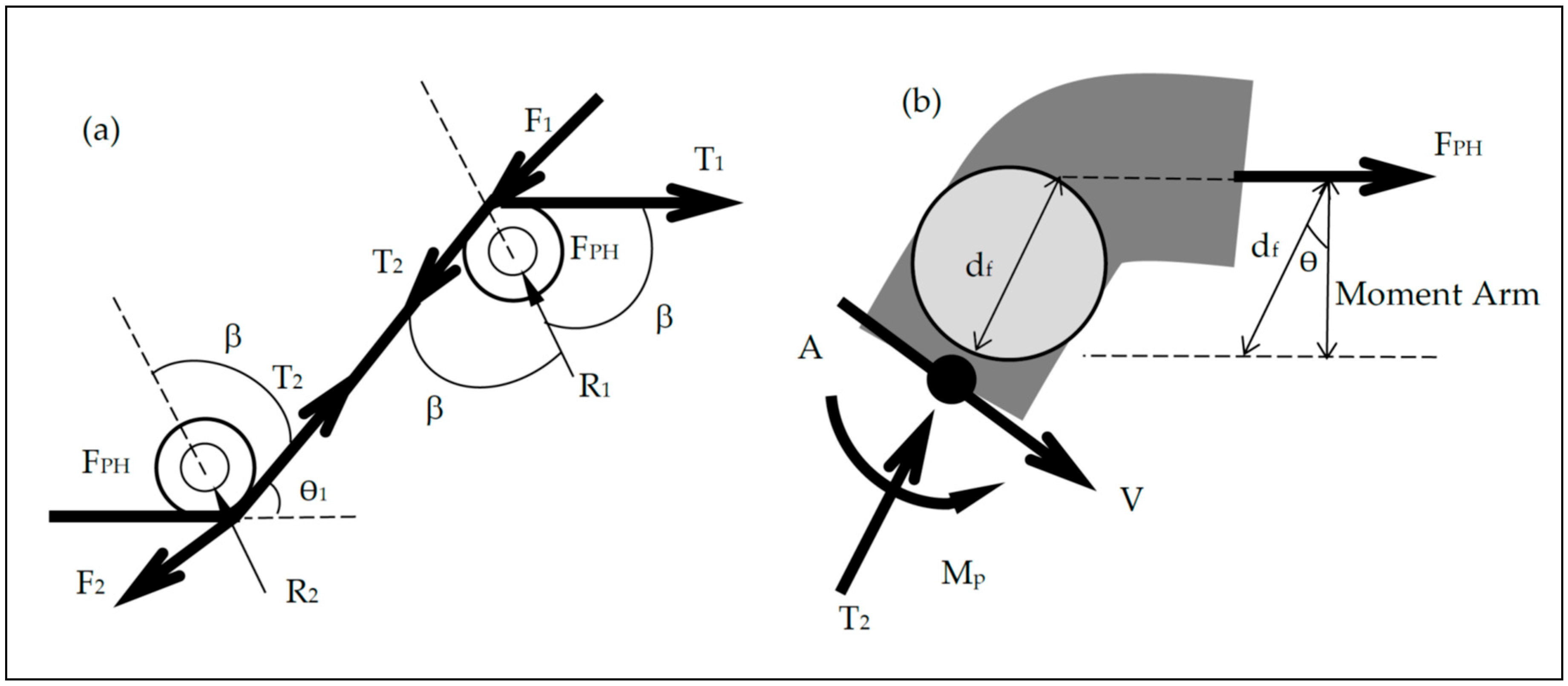
3.1.1. Effect of Number of Bends nb

To investigate the effect of the number of fibre bends or hooks, specimens with 3D, 4D and 5D fibres with Vf = 1% were all compared. All fibres had an embedded length of approximately LE = 25 mm (which was established before the test), an identical aspect ratio (Lf/df = 65) and similar compressive strengths. A maximum pull-out strength of Pmax = 267 N was recorded for the 3D sample, while Pmax = 615 N and Pmax = 662 N were recorded for both the 4D and 5D samples, respectively. Although not only the number of bends differed between the three fibres but also the maximum fibre tensile strength, the 3D and 4D samples failed after the complete straightening of bends, while the 5D samples showed a partial straightening of bends, and then all fibres were pulled out without fibre rupture taking place. This suggests that the number of bends or hooks is the most influential factor in the behaviour of fibrous lightweight concrete (with the same fibre aspect ratio) and shows that a higher number of bends or hooks may lead to higher pull-out strength since more plastic hinges are developed and more bend straightening is required due to a better concrete–fibre bond being developed. Also, it can be observed that the post-cracking ductility increases with the increase in the number of bends as the load can be maintained at a high stress level for a longer duration of the test. It should be noted, however, that most 5D hooks appeared to not be completely straightened after pull-out (Figure 8). The reasons behind the partial hook straightening of the 5D fibre will be further investigated in Section 3.3.

3.1.2. Effect of Fibre Aspect Ratio af

To investigate the effect of the fibre aspect ratio af (defined as Lf/df), the 3D* fibre with af = 80 (Lf = 60 mm, df = 0.75 mm) was tested. The 3D* fibre had nearly identical properties, including the maximum fibre tensile strength, length and geometrical hooks to those of the control 3D fibre with af = 65 (Lf = 60 mm, df = 0.9 mm). However, the 3D* fibre developed a maximum pull-out strength of P = 316 N, which is 15% higher than that of the control 3D fibre. This shows that a higher aspect ratio leads to the development of a higher tensile strength.

3.1.3. Effect of Fibre Length Lf

To study the effect of the fibre length, the 3D** fibre with aspect ratio af = 65 (Lf = 35 mm, df = 0.55 mm) was tested. The 3D** fibre has an almost identical hook length to the 3D fibre and a slightly higher maximum fibre tensile strength. This fibre proved to be somewhat the weakest as it generated a pull-out force of only P = 92 N. Hence, the longer the fibre, the more efficient the crack arresting mechanism. This agrees well with Abdallah et al.’s [42] findings.

3.1.4. Effect of Fibre Dosage Vf

To study the effect of increasing the fibre dosage, mixes of similar fibre types are compared for different fibre volume fractions (Vf = 1% and 2%). For 3D fibres, the pull-out strength was recorded to be P = 570 N at Vf = 2%, which is 53% higher than the corresponding pull-out strength at Vf = 1%. However, for 4D and 5D fibres, the increases in strength (when Vf was raised from 1% to 2%) were calculated to be 44% and 50%, respectively. This enhancement was expected since the fibre dosage was doubled.

3.1.5. Effect of Compressive Strength flck

To examine the effect of lowering the concrete grade, specimens with compressive strength flck = 40 MPa reinforced with 5D fibres were tested. When their pull-out behaviour was compared to that of concrete specimens with flck = 30 MPa (also reinforced with 5D fibres), the pull-out tensile strength developed was 7% higher for the higher concrete grade. Hence, increasing the concrete grade by increasing the cement content and reducing the w/c ratio leads to a reduction in air pores around the embedded hooks, which increases the mechanical bond strength. This behaviour was also reported by Abdallah et al. [48].

3.1.6. Effect of Embedded Length LE

To examine the effect of varying the embedment length LE on the tensile strength, mixes sharing the same properties (flck = 30 MPa, Vf = 1%, 3D) but with different embedded lengths (LE,1 = 18.4 mm and LE,2 = 23.5 mm) were compared. For both specimens, a similar pull-out load (Pmax ≈ 265 N) was measured, albeit the specimen with a higher embedded length provided higher ductility. The latter will be inspected by calculating the pull-out work performed in Section 3.2.2. It is interesting to observe that some specimens experienced concrete fracture and then pull-out at the hook’s location, such as the specimen with the following properties: flck = 30 MPa, Vf = 1% and 5D fibre. Figure 9 shows a concrete specimen fracturing outside the notch. For this particular sample, the embedded length was only 12 mm, while the hook length is approximately 10.1 mm for 5D fibres. Therefore, the embedment length LE was deemed insufficient. Another identical specimen with LE = 14.45 mm was seen to be capable of undergoing complete hook straightening before being pulled out. Therefore, altering the embedment length of the hooked-end fibres for lightweight concrete has no practical effect on the maximum pull-out strength but merely increases the ductility via frictional pull-out as long as LE provides enough hook bond (i.e., when LE ~ Lh + 4.5 mm with Lh being the hook length). This phenomenon was also observed with 3D and 4D fibres. Hence, if the fibre diameter df is to be factored into the previous equation, then LE = Le ~ Lh + 5df, with Le being the length required to develop the maximum pull-out strength of the fibre based on pull-out tests. This finding also agrees with Abdallah et al.’s [48] observations, who recommended LE = Lh + 5 mm to obtain the maximum pull-out load, Pmax.

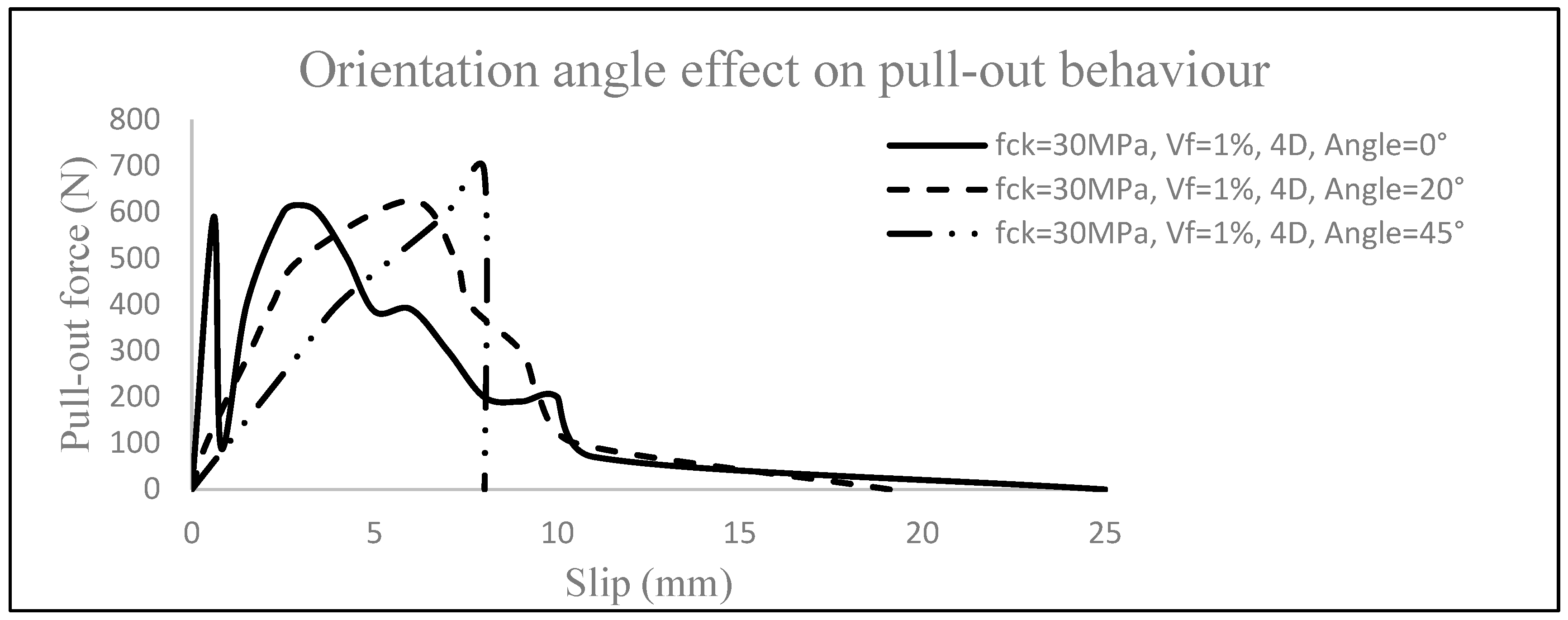
3.1.7. Effect of Fibre Inclination Angle ϴf

To study the effect of the orientation angle, which is the angle between the tensile load applied and the fibre, 4D fibres at angles 20° and 45° were tested and plotted (Figure 10). It can be seen that the specimen whose fibre was oriented at 45° failed in concrete fracture similar to the specimens with an inadequate embedded length, although it developed a higher pull-out tensile strength (P = 690 N) than its counterparts. By contrast, a pull-out strength of only P = 626 N was recorded for the specimen with an orientation angle of 20°. However, the latter failed in ductile fibre pull-out mode. This pull-out strength is 11 N higher than that developed by the control specimen of flck = 30 MPa, Vf = 1% and 4D fibre with an orientation angle of 0°. Hence, it can be deduced that by increasing the orientation angle, the load increases and takes place at a larger slip. If the angle is too high and the concrete is not dense enough, the concrete can fracture and fail in a brittle manner. These findings agree with Robins et al.’s [45] study, with the exception that the fibres used in that work ruptured at a higher inclination angle. However, in the present work, the concrete fractured. This could be attributed to the enhanced tensile strength of the 4D fibres as compared to the fibres mixed in the experiments carried out by Robins et al. [45] coupled with the porous nature of LWAC, which could induce cracking and fracturing much more readily.
It is important to note that for some specimens, such as the one shown in Figure 10 with an orientation angle of 0°, the load increased to an unexpected value (in this example 590 N) before any activation of fibre pull-out. This value is thought to be overly high for concrete with a tension of flck = 30 MPa, which usually has a pull-out strength of Pmax = 244 N. Upon the inspection of the pulled-out specimen after the test, it was observed that a lightweight aggregate positioned at the notch was split, which led to a drastic increase in the load. It was also interesting to measure that the aggregate had a diameter of almost 5 mm (Figure 11), i.e., 7 mm smaller than that of the notch, which should not force the crack to go through it. However, this can be justified, since for other material tests such as compression tests—detailed in earlier studies [30,31]—some of the aggregates were sheared through in a similar manner. In the same test, this was followed by a sudden drop in the load before fibre activation took place.

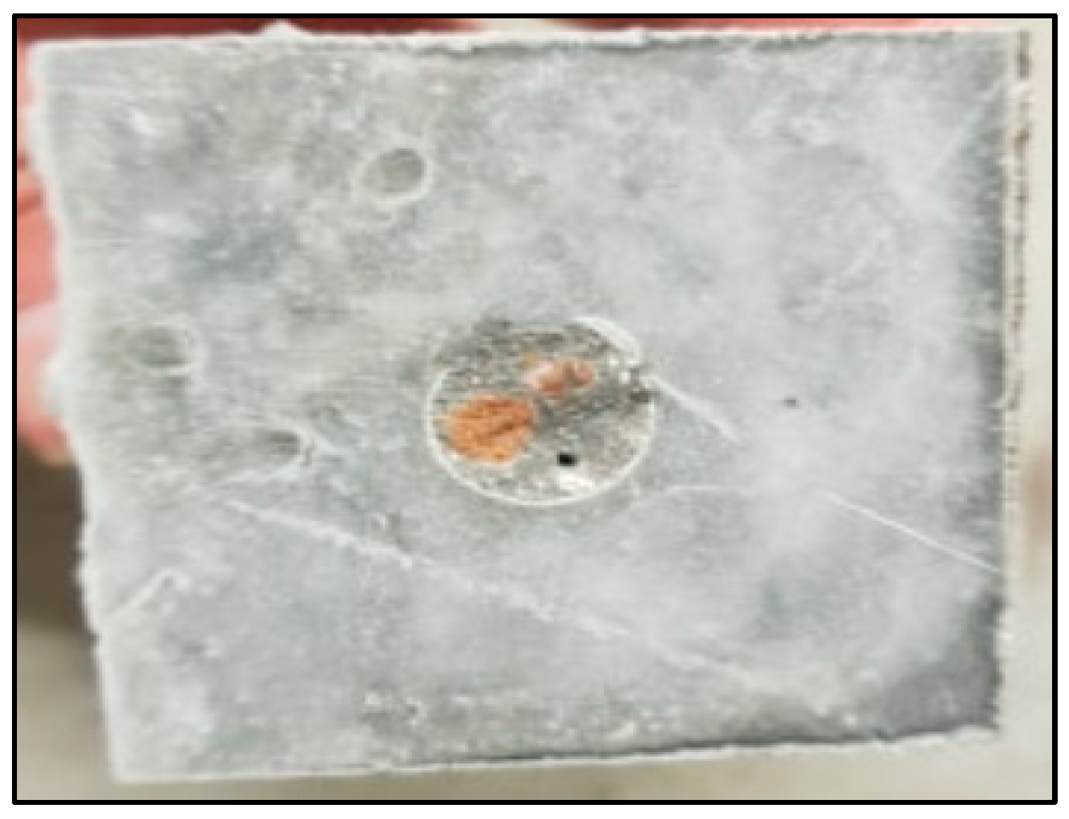
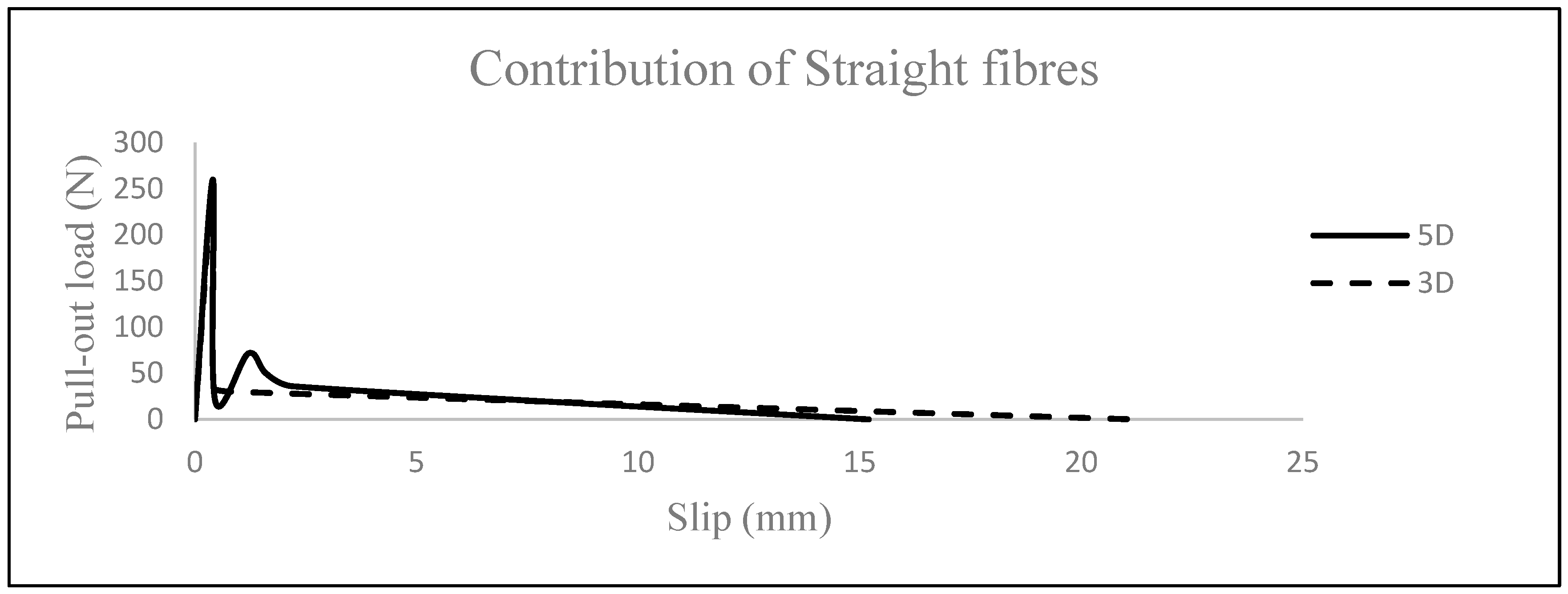
3.1.8. Adequacy of Smooth Fibres

In order to investigate the possibility of mixing lightweight concrete with straight smooth round fibres, 3D and 5D fibres with hooks being cut off were tested, and the results are depicted in Figure 12. The difference in the embedded length is due to the longer 5D hooks (about 10 mm for each hook, which resulted in 40 mm of fibre remaining in a straight length) compared to the 3D hooks (about 5 mm for each hook, which resulted in a 50 mm fibre length). For both fibres, the load dropped right after cracking at about 35–50 N, and a decay curve ensued with hardly any upgrade in load. These values agree with Alwan et al.’s [46] pull-out loads from tests with shorter straight and smooth DRAMIX fibres embedded in concretes with low strengths. Also, Abdallah and Rees [57] tested straight DRAMIX fibres embedded in concrete with a compressive strength of 33 MPa and recorded similar values. The tests in the present study demonstrate the importance of hooks in the structural responses of fibrous lightweight concrete since the hook-less 5D and 3D fibres only maintained the load until the eventual pull-out. Thus, it can be concluded that the usage of straight fibres is not recommended for lightweight concrete due to its low densification, resulting in a weak fibre–matrix interfacial bond strength, which causes smooth straight fibres to be pulled out easily.
It is important to note that for all of the preceding specimens examined according to the pull-out test, any observed upgrade in the uniaxial tensile or pull-out strength (due to the addition of fibres) might not occur in a different structural element where fewer fibres than those designed for this study are actually present in the vicinity of the crack. Other reasons include an insufficient embedded length and unfavourable fibre orientation angle (for example, an angle vertical to the tensile load or an angle which causes concrete fracture above 45–50°). All of these reasons can lead to lowering of the uniaxial tensile strength developed due to fibre reinforcement. By contrast, a favourable inclination angle (about 20°) and an optimum embedment length (LE = Lf/2) would enhance the pull-out behaviour and energy dissipation. For this reason, fibre orientation factor η will be discussed later on to examine its effect on the post-cracking uniaxial tensile stress.

3.2. Key Characteristics of the Uniaxial Tensile Behaviour of SFRLC

Table 5 summarises the key parameters defining the uniaxial tensile behaviour of fibrous composite. Each of these parameters will be discussed next.

3.2.1. Maximum Uniaxial Tensile Stress flctm,m

The maximum uniaxial tensile stress flctm,m is the larger value of the uniaxial tensile stress due to plain concrete flctm,p or post-cracking residual tensile stress due to fibre concrete flctm,f1. flctm,p can be calculated using the pull-out response by dividing the Pmax value for plain specimens by the area of the notch. To calculate the contribution of steel fibres to the tensile strength of concrete at any instant, the rule of composites is used. Thus, the actual composite stress is
f l c t m , f i = σ a v , f + σ c
σav,f and σc are the average stresses of the fibre and concrete, respectively.
From [26,58,59,60], the fibre contribution can be calculated using the following expression:
σ a v , f = σ f V f η 0
where Vf is the fibre volume fraction, and η0 is the fibre orientation factor taken as 0.41.
Hence, Equation (1) becomes
f l c t m , f i = σ f V f η 0 + σ c 1 V f
The classical contribution of both concrete and steel fibres in an SFRC composite remains true for SFRLC with σf ≈ 0 before cracking and σc = 0 after cracking since it was demonstrated from the experiments that practically only steel fibre reinforcement contributes to tension stiffening for lightweight concrete immediately after matrix cracking. Following cracking, once the maximum pull-out strength Pmax for a single fibre is known, the fibre stress σ f can be readily derived using Pmax/Af with Af as the area of a single fibre. Hence, at post-peak, the maximum residual stress (or first residual stress flctm,f1) of SFRLC can be calculated using the following equation:
f l c t m , f 1 = σ f p e a k V f η 0 = P m a x / A c V f η 0
flctm,m is increased by the addition of fibres, an increase in Vf and an increase in the number of bends. It should be noted that the post-cracking residual tensile stress flctm,f1 used to derive flctm,m for fibrous specimens in Table 5 is unfactored. To account for the random distribution of fibres in a 3D real fibrous concrete structural element, an orientation factor of η0 = 0.41 is introduced [26]. The orientation factor can be defined differently in the literature (η0 = 0.5 [61] and variable according to size effect [34]).
Figure 13 shows the uniaxial tensile strength flctm,f1 of the SFRLC specimens tested, normalised to the corresponding plain concrete strength of the same grade flctm,p. From Figure 13, the maximum SFRLC post-cracking residual uniaxial tensile strengths flctm,f1 reinforced with Vf = 1% were 54%, 126%, 135%, 92%, 46%, 7% and 15% of the plain concrete strength of the same grade flctm,p when 3D, 4D, 5D, 3D**, 3D*, hook-less 3D and hook-less 5D fibres were added, respectively. This discrepancy in enhancing the residual fibrous tensile resistance of SFRLC between these mixes was essentially due to the effectiveness of the bond between concrete and steel fibres. In Figure 13, it can be seen that with the addition of Vf = 1%, all fibres showed a residual tension softening behaviour with the exception of 4D and 5D fibres, which exhibited a residual tension hardening behaviour. However, with the increase in Vf to 2%, 3D fibres were also able to induce a tension hardening effect based on the flctm,m/flctm,p ratio being larger than 1.

3.2.2. Pull-Out Work

Work performed is a measurement of ductility and is estimated by calculating the area under the pull-out load–slip curve. The work performed is governed by three parameters, the fibre type, fibre volume fraction and embedment length. From Table 5, it appears that the fibre type is the most influential of the three parameters. For instance, 5D fibres with Vf = 1% brought about a higher total work than 4D fibres with Vf = 2% for similar LE and concrete strength. Hence, 5D fibres are seen to provide the highest work performed followed by 4D, 3D, 3D* then 3D**. Also, the higher the volume fraction Vf, the higher the total work performed. Moreover, clearly the larger LE, the more the energy dissipation through fibre frictional pull-out, which in turn translates to a more ductile response of the pull-out load–slip curve.

3.2.3. Bond Strength

Several equations were developed in the past to quantify and assess the bond behaviour between fibres and concrete. The most important ones are summarised in Table 5. The average bond stress τav [53] is defined as the maximum pull-out strength divided by the initial bond area between the concrete and embedded fibre:
τ a v = P m a x / π d f L E
where τav (MPa) is the average fibre–matrix interfacial bond shear stress, df (mm) is the fibre diameter and LE (mm) is the initial embedment length defined as the shorter length of the embedded fibre after the crack takes place at the notch in the pull-out specimen. Since the experiments conducted showed that the embedment length plays no practical role in altering the maximum pull-out strength but merely affects the frictional pull-out, the average bond strength gives a poor estimate of the bond if the latter is to be directly linked to the peak strength. The equivalent bond strength τeq [62] is defined as the fibre–matrix interfacial bond stress during the entire fibre pull-out process using the total work due to fibre pull-out:
τ e q = 2 W p / π d f L E 2  
where Wp (N.mm) is the total work performed by the fibre, which is equivalent to the area under the stress–slip once concrete cracking develops. The equivalent bond strength governs the effectiveness of concrete crack control and can therefore be regarded as a direct measure to evaluate the structural performance, including the ductility and ultimate loading capacity of fibrous concrete. Since Pmax is affected only by the fibre hook contribution, then the embedded length must be at least LE = Le = Lh + 5df for complete fibre hook straightening. It should be noted that a higher value of the embedded length LE > Le = Lh + 5df will not increase the pull-out strength, as shown previously. Equation (4) is rearranged to become
P m a x = τ u l t π d f L h + 5 d f
Hence, the ultimate bond strength of the SFRLC composite with hooked-end fibres can be written as
τ u l t = P m a x / π d f ( L h + 5 d f )
The ultimate bond strengths for the fibres mixed with different lightweight concrete grades are summarised in Table 5. It should be noted that for the hook-less 3D and 5D fibres, Lh was taken as the total embedded length.
It can be seen from the experimental data that 4D fibres resulted in the highest ultimate bond strength, therefore exceeding both 3D and 5D ultimate bond strengths for the same concrete grade of flck = 30 MPa. On the other hand, 3D** developed the lowest bond strength amongst hooked-end fibres. Also, it should be noted that by increasing the concrete grade, the ultimate bond strength increased as well. This was seen for the 5D and 3D specimens tested with flck = 30 and 40 MPa. In addition, 3D* fibres with an Lf/df = 80 aspect ratio developed an average bond strength 55% higher than that of 3D fibres with Lf/df = 65. Hence, for DRAMIX hooked-end fibres, the high aspect ratio brings about a higher bond strength. Lastly, the lowest bond strength was calculated for the smooth straight fibres (i.e., hook-less fibres).

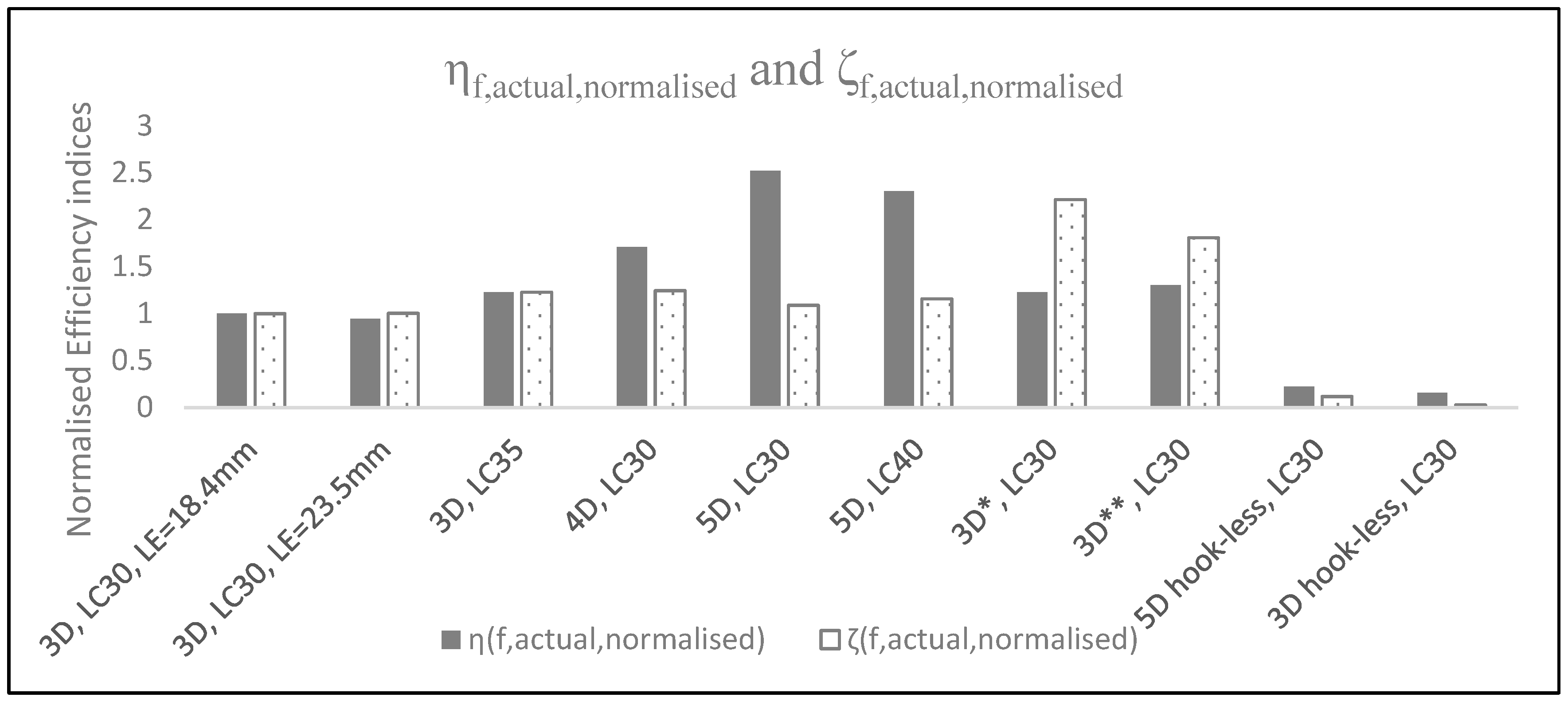
3.3. Fibre Optimisation

In order to determine the fibres that are best suited for reinforcing the lightweight concrete tested, a brief optimisation study was carried out and is discussed next.

3.3.1. Fibre Stress Efficiency

The fibre stress efficiency values are summarised in Table 5. Fibre efficiency is a direct measure of the effectiveness of fibre reinforcement for a particular concrete. A very low value indicates an under-performance of fibre reinforcement, while a very high value may indicate over-performance of fibre reinforcement, which may lead to fibre rupture. Also, fibre efficiency can be a direct measure for the calculation of the formation of plastic hinges and the straightening of fibres. Fibre stress efficiency ξ is calculated by dividing the maximum stress by the ultimate stress of the fibre. Amongst all the fibres tested, the 4D and 3D* fibres showed the highest fibre stress efficiency, followed by the 5D, 3D, 3D**, hook-less 3D and 5D fibres. Since the 3D, 3D* and 3D** fibres have roughly identical hook shapes and sizes, the higher aspect ratio and fibre length are therefore the most responsible parameters for developing fibre stress efficiency given that the concrete strength is kept constant. Increasing the inclination angle led to a greater fibre efficiency, as seen with the 4D fibres; however, this could cause concrete fracture for the porous lightweight concrete matrix. A higher concrete grade, which means a lower w/c ratio and a denser concrete matrix, would bring about a better bond, which in turn would result in a higher fibre stress efficiency. Lastly, LE played no factor in increasing the fibre stress efficiency.

3.3.2. Fibre Energy and Bond Indices

In order to further investigate the behaviour of SFRLC for fibre optimisation, an assessment of energy dissipation and bond strength is vital. Qi et al. [55] aimed to choose the fibre type that is the most suitable for the concrete tested by defining both the energy dissipation index ηf and bond strength index ζf using a single fibre pull-out test.
η f = W p / A f L f
ζ f = τ a v / A f L f
However, these two equations need adjustment of the accuracy of their mechanical meaning based on the pull-out tests carried out previously. This is the case because it was shown that the fibre length Lf plays no role in enhancing the bond strength and plays a minimal role in energy dissipation when compared to LE. Therefore, Equations (9) and (10) become
η f , a c t u a l = W p / A f L E
ζ f , a c t u a l = τ u l t / A f ( L h + 5 d f )
Figure 14 shows the normalised actual efficiency indices, which are calculated by dividing the actual efficiency indices by the control 3D specimen actual efficiency indices. It can be seen that the more extensive the hooks, the higher the energy dissipation efficiency index. Consequently, the 5D and 4D fibres showed the highest energy efficiency indices due to longer hooks, which increase energy dissipation. Also, the higher the aspect ratio for a similar fibre length, the higher the energy dissipation efficiency index, as can be seen with the 3D* fibre (af = 80) compared to the 3D and 3D** fibres, which have a similar aspect ratio (af = 65). The fibre bond strength efficiency index varies, with the 3D* fibre having the highest value and the 3D and 5D fibres showing the lowest values.

3.3.3. Fibre Plasticity Study

As shown in Figure 8, all fibres appeared to be straightened and then pulled out of the lightweight concrete notched prisms with the exception of some 5D specimens. When the 5D fibres were not fully straightened, a local fracturing of the matrix followed, which is an unfavourable mode of failure. When fibres are not fully straightened, a lack of full plastic hinges are developed, which is why the 5D fibre stress efficiency was low. To this end, the fibre tensile stress was thought to play a secondary role in the behaviour of the pull-out specimens; however, the high yield stress of the 5D fibres combined with the hook geometry and angles (summarised in Table 1) are thought to play a negative role in preventing steel yielding of fibre and thus increase the possibility of fracture. To investigate the latter, Alwan et al.’s [46] pulley model, depicted in Figure 15, was adopted to determine the magnitude of the load causing the plastic hinges to form before hook straightening. This theoretical pull-out load was then compared to the corresponding experimental one.
In Figure 15, FPH corresponds to the cold work needed to straighten the steel fibre at the location of the plastic hinge, Mp is the plastic moment of the steel fibre and T2 is the chord tension in the fibre. Since the purpose of this section is to determine the force required to develop a plastic hinge and straighten the fibre, FPH was calculated for 3D, 4D and 5D fibres.
For point A,
F P H = M p / d f cos θ
The plastic moment Mp is suggested by Alwan et al. [46], who carried out pull-out experiments on 3D DRAMIX fibres embedded in concrete with w/c ratios ranging from 0.5 to 1.0. In Alwan et al.’s study [46], the pull-out loads were around 150–180 N for 3D fibres with an aspect ratio of 0.6 (df = 0.5 mm, Lf = 30 mm), which are comparatively higher than the pull-out loads recorded in this work for the 3D** fibre with df = 0.55 mm and Lf = 35 mm, whose pull-out loads were around 90–105 N. The plastic moment in [46] is
M P = f y · π r f 2 / 2 · d f / 3
where rf is the radius of the fibre. It should be noted that Equation (14) was thought to be suitable for concrete where an elastic–plastic condition is sufficient for fibre pull-out. Abdallah et al. [47] suggested the following plastic moment and criticised that Equation (14) underestimates the pull-out for ultra-high-strength concrete:
M P = f y · π r f 2 / 2 · d f / 3 · π / 4
Based on Alwan et al.’s [46] theoretical hooked-end 3D fibre pull-out process depicted in Figure 16 (which agrees with the current experimental study), the maximum pull-out load is
P m a x = P 2 = P 1 + P = P 1 + T 1
where P or T1 is the contribution of plastic hinges to the pull-out load and P1 is the pull-out load at the onset of complete debonding. Pmax or P2 can be found in Table 4. The total number of possible plastic hinges is 2, 3 and 4 for 3D, 4D and 5D fibres, respectively. Since hooked-end and straight fibres’ pull-out behaviour shares only the pull-out load up to complete debonding P1 [47], then according to the tests carried out on DRAMIX hooked-end fibres, P1 = 30–55 N. P1 could also be calculated according to the analytical study by Naaman et al. [63], but this is outside the scope of this work.
The pull-out load due to plastic hinges T1 can be calculated for 3D fibres [46] as follows:
T 1 ( 3 D ) = 2 F P H 1 + μ × cos β 1 μ × cos β / 1 μ × cos β
μ is the coefficient of friction between concrete and steel, taken as 0.5, and β was measured, and the results are shown in Table 1. Using Equation (17), FPH can be calculated and compared to that calculated using Equation (13). If the experimental FPH value from Equation (17) is higher than the theoretical one calculated using Equation (13), then the fibre was straightened following the formation of two plastic hinges for 3D fibres.
Abdallah et al. [47] adapted this model to 4D and 5D fibres.
Equation (16) remains valid for both 4D and 5D fibres since the P1 load was similar. By applying the pulley model in a similar manner to Equation (17), as depicted in Figure 17 and Figure 18, the pull-out load due to plastic hinges T1 can be calculated for 4D and 5D fibres as follows:
T 1 ( 4 D ) = F P H 3 + 2 μ × cos β 1 μ × cos β 2 1 + μ × cos β 1 μ × cos β + 1 / 1 μ × cos β
T 1 5 D = F P H 4 + 2 μ × cos β 1 μ × cos β 3 + 2 μ cos β 2 1 + μ × cos β 1 μ × cos β + 1 + 2 1 + μ × cos β 1 μ × cos β + 1 / 1 μ × cos β
Table 6 shows that the theoretical model used to calculate Mp in Equation (14) suggested by Alwan et al. [46] seems to overestimate the behaviour of pull-out since FPH,theoretical > FPH,test for all fibres, which translates into fibres not becoming straightened at the end of the test. Given that all fibres with the exception of the 5D fibre were straightened by the end of the test, a new Equation (20) was proposed to calculate Mp, which considers the comparatively weak lightweight concrete and its porous nature. This equation assumes that the effective distance between the centroids of tension and compression forces in a plastic stress distribution diagram for a steel fibre circular section is 2 r f π 15 ( 2 r f 3 for Alwan et al.’s [46] model, and a true distance of 8 r f 3 π for Abdallah et al.’s [47] model). Thus, for porous lightweight concrete, the fibres were assumed to not undergo heavy straining after developing plastic hinges before becoming straightened and eventually being pulled out.
M P = f y · π r f 2 / 2 · d f / 3 · π / 5
As seen in Table 6, the new model marginally underestimates the value of FPH by a maximum of 3% for 3D, 3D** and 4D fibres while predicting that they become straightened (FPH,theoretical < FPH,test). On the other hand, the 5D fibre clearly does not become straightened according to this model. It should be noted that while the majority of 5D specimens appeared to be completely unstraightened, some 5D specimens looked partially straightened.
Considering the preceding discussion, it is safe to assume that unless the concrete is of high strength and therefore capable of providing a strong fibre–matrix interfacial bond, such as the ultra-high-strength concrete tested by Abdallah et al. [42,47,48], it is recommended that multiple-bend fibres with a high tensile strength (such as 5D fibres) should not be employed as reinforcement for concrete with a low concrete grade since they might cause local fracturing during the fibre straightening process. Given that there exists a possibility of matrix fracture due to 5D fibres not fully developing plastic hinges and becoming straightened, 4D and 3D* fibres appear to be the most efficient fibres for use in the LWAC sample tested depending on their structural usage, with the aspect ratio af playing a significant role in bond strength efficiency and the number of hooks having a greater impact on the energy dissipation efficiency. Finally, it could be argued that 4D fibres with a higher af value would further increase the efficiency indices and thus enhance the behaviour of SFRLC.

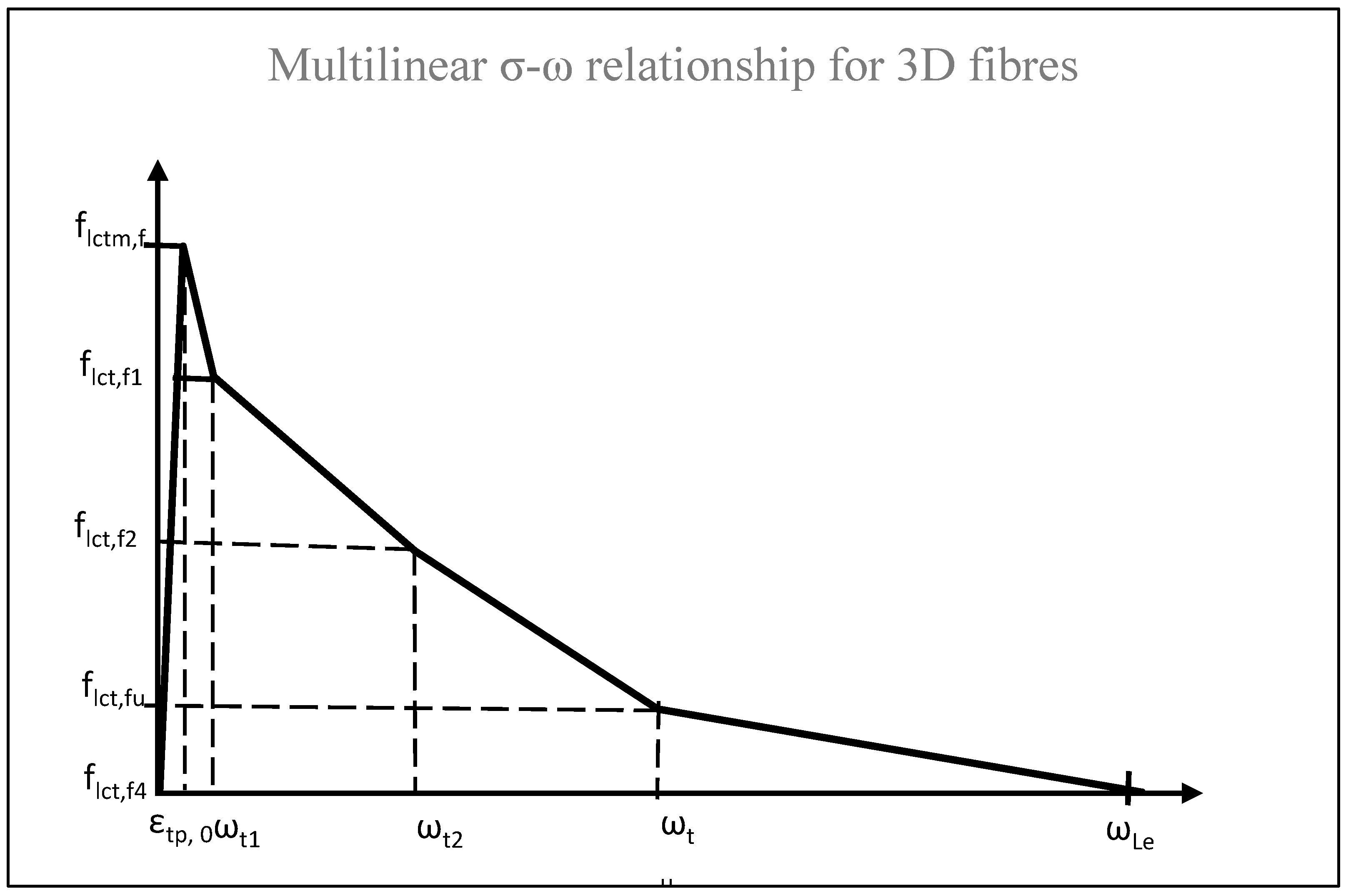
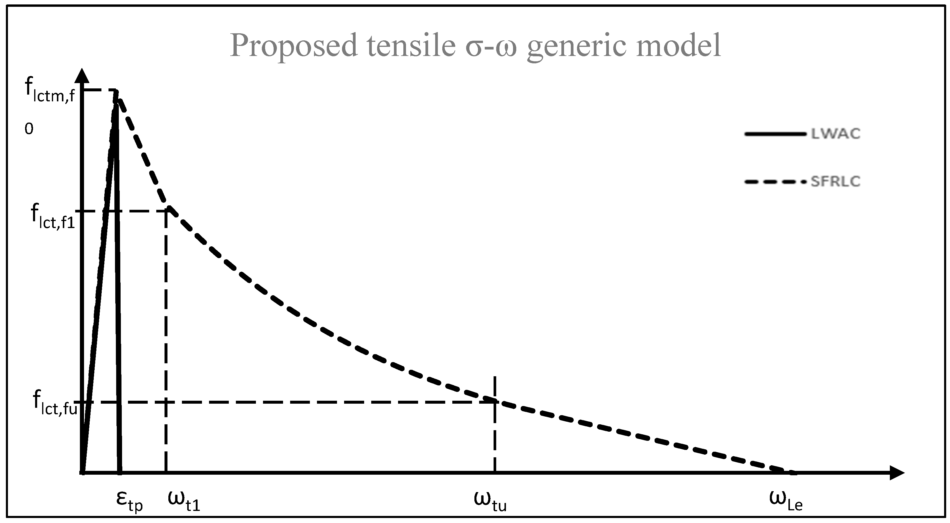
3.4. Proposed Constitutive Tensile σ-ω Model

Although it cannot be used directly for engineering calculations such as beam section analysis, the tensile stress–crack width (σ-ω) relationship is preferred to the stress–strain (σ-ε) relationship because it represents the actual behaviour of the fibrous material, especially after cracking. It is derived from analysing the output results of the uniaxial tensile test, is independent of the member size effect, and can be directly applied from the pull-out tests used for FEM [64]. Also, the σ-ω relationship can provide the information needed to design the serviceability limit state, including fatigue and shrinkage. To be able to use the σ-ε relationship for section analysis based on pull-out tests, the strain values are derived using the crack width and the structural characteristic length lcs (using the relation ε = ω/lcs), which varies depending on the specimen size, Vf, fibre type, reinforcement, loading level and matrix strength. No agreement has been achieved to determine lcs; however, for beams, lcs can be chosen as the minimum of srm and hsp, where srm is the mean distance between cracks and hsp is the unnotched depth [64,65]. It should be noted that the proposed model ignores the slight drop in load following matrix cracking, which lasted in the range of 0.05 to 0.1 mm slip before the load was increased. This was deemed to have a negligible practical impact on the accuracy of the σ-ω relationship. Figure 19 depicts the idealised proposed multilinear stress–crack width relationship based on the uniaxial tensile pull-out tests for 3D fibres.
Due to the sensitivity of the pull-out machine, the accuracy of measuring the early slip pre-peak was somewhat limited. Hence, the rule of fibrous composites was adopted to determine the strain at peak before cracking for plain concrete εtp. The Young’s modulus of elasticity of the concrete in tension is as follows:
E c t = E m t V m + η l η o E f V f
where Emt and Ef are the plain concrete matrix and the fibre’s Young’s moduli of elasticity in tension, respectively; Vm and Vf are the volume fractions of the matrix and fibres, respectively; ηl is the fibre length efficiency; and η0 is the fibre orientation factor.
Similarly to Lok and Xiao [59], it is assumed that the initial modulus of elasticity in tension is equal to that in compression. Hence,
E m t = E c
Also, based on the pull-out tests, it was evident that σf was low since a relatively negligible increase or decrease in the uniaxial tensile strength of the concrete was recorded pre-crack for fibrous concrete specimens. Once cracking took place, the load abruptly degraded, followed by mobilisation of the fibre crack arresting effect. Therefore, before cracking takes place, Equation (21) with Vm ~ 1 becomes
E c t E c
The strain at peak can now be calculated as shown below, where flctm,p is the stress of the plain concrete.
ε t p = f l c t m , p / E c t
As previously shown in the pull-out tests, the uniaxial tensile stress at which the crack took place for SFRLC was similar to that of the plain lightweight concrete. The stress due to fibres immediately before cracking can be estimated using the following equation:
f l c t m , f 0 = f l c t m , p
Plain lightweight concrete uniaxial tensile stress can be written as
f l c t m , p = 0.26 f l c m 2 / 3 × 0.4 + 0.6 ρ / 2200
Equation (26) was adapted from Eurocode 2 [66], where flcm (MPa) is the mean compressive strength of lightweight concrete based on the cylinder compression tests, and ρ is the oven density of concrete (kg/m3). Using the above equation, R2 was found to be 0.96.
From Figure 19, the first residual uniaxial tensile stress flct,f1 of SFRLC, which takes place after cracking as peak of either tension hardening or softening, can be derived using Equation (4) from the pull-out test or regression Equation (27) (R2 = 0.95). The crack width ωt1 at flct,f1 varied for all the SFRLC specimens, with specimens having stronger fibres showing the highest ωt1 values. For the majority of specimens, the ωt1 value ranged from 0.4 to 0.5 mm for 3D fibres, 0.5 to 0.8 mm for 4D fibres and 1.1 to 1.4 mm for 5D fibres. This largely agrees with Abdallah et al.’s [57] results of pull-out tests on normal strength concrete of 33 MPa. The residual slip ωt1 can also be calculated based on the following regression Equation (28) (R2 = 0.89). The fibre reinforcing factor ρ f = V f ( L f + L e ) / d f ( δ · κ ) is detailed elsewhere, and ρ′f = ρf (for Vf = 1%).
f l c t , f 1 = η 0 V f f l c t m , p ρ f 172.1 + 35.5 f l c t m , p ρ f
ω t 1 = 0.2124 ρ f 2 + 0.3775 ρ f
Using the idealised stress–crack width relationship in Figure 19, the load drops at a further slip of 2 mm to 3 mm. This was denoted as ωt2. After thorough inspection of the pull-out tests, ωt2 was deemed to be approximately equal to the hook arm L2 shown in Figure 2. The observation that ωt2 = L2 is also supported by the work carried out on hooked end fibres in [46] and recent revisions from Abdallah et al.’s [57] pulley model on DRAMIX hooked-end 3D, 4D and 5D fibres. In the latter study, after fibre debonding, two plastic hinges were developed for 3D fibres (three plastic hinges for 4D fibres and four plastic hinges for 5D fibres). At this stage, the second residual pull-out stress due to fibre contribution was recorded. Once the slip reaches L2, the mechanical anchorage mechanism becomes supported by only one plastic hinge for 3D fibres, two hinges for 4D fibres and three hinges for 5D fibres, which results in a significant drop in the pull-out load. From the pull-out tests, the second residual pull-out stress flct,f2 recorded at ωt2 = L2 was 30 to 40% lower than flct,f1 for the 3D, 4D and 5D specimens. Thus, for design purposes,
f l c t , f 2 = 0.60 × f l c t , f 1
When the crack width ωtu = Lh (the full length of the hook), the load drops significantly, and only frictional pull-out becomes responsible for the SFRLC behaviour, while one plastic hinge and two plastic hinges remain responsible for the behaviours of 4D and 5D fibres, respectively. Hence, at ωtu = Lh, the load drops to about 10 to 25% for all the specimens tested and frictional pull-out starts to take place. Thus, the stress flct,fu can be written as
f l c t , f u = 0.10 × f l c t , f 1
It is vital that the hook of the fibre is fully embedded in concrete for the fibrous mix to develop the maximum residual stress flct,f1; hence, the final crack width can be written as
ω L e = L e = L h + 5 d f
where ωLe is the effective length crack width in mm. For design purposes the ultimate tensile strength flct,f4 can be assumed to be 0.
A similar semi-empirical approach can be adopted to derive the tensile behaviour of 4D and 5D fibres. The proposed multilinear uniaxial tensile σ-ω relationships suggested are specific to the type of fibre used and depend on experimental strength reduction factors fully based on pull-out tests. Hence, these reasons render the models laborious and reliant on uniaxial tensile tests. In order to make the model more generic (covering hooked-end, crimped or straight fibres embedded in concrete matrices with different strengths) and easy to use, and to avoid any reliability on the pull-out or uniaxial tensile tests, the generic model shown in Figure 20 is suggested.
The tensile stress in Figure 20 is explained in the equations below.
f l c t = E c t · ε t                                                               if     ε t ε t p f l c t m , f 0 + f l c t , f 1 f l c t m , f 0 ω t / ω t 1     if   0 < ω t ω t 1 f l c t , f 1 e ζ                             if   ω t 1 < ω t ω t u
ζ = ω t ω t 1 / ω t u · n b / ρ f
The tensile stress should be 0 at ωLe. ωtu is the Lh value for hooked-end fibres, and the length of one wave or the turn of crimped fibres and the length of a straight fibre is 10. nb is the number of bends in one hook (one for 3D, two for 4D and three for 5D). nb is taken as half the total number of waves for crimped fibres (usually four or three), and there are five waves for straight fibres.

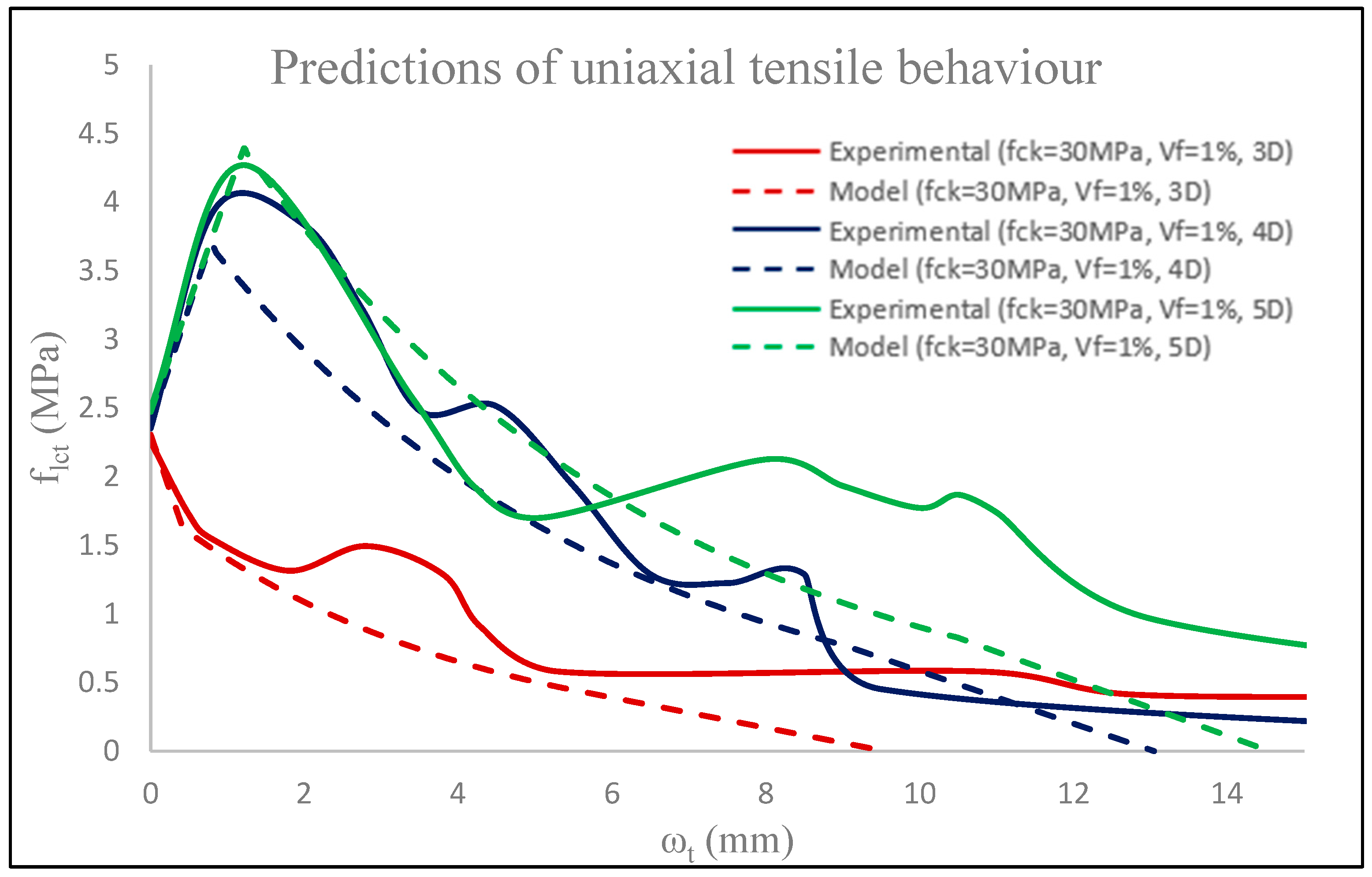
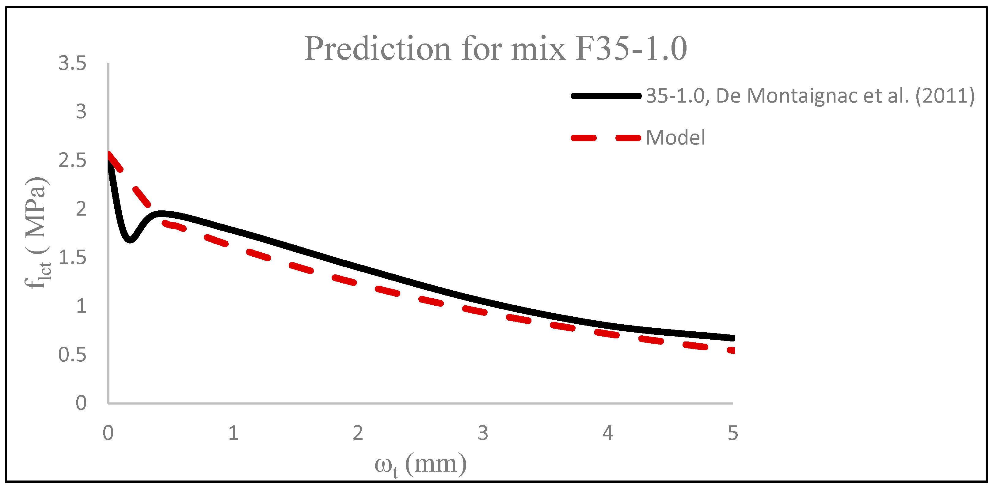
3.5. Validation of Tensile σ-ω Model

In order to validate the proposed model shown above, the average experimental uniaxial tensile behaviours of 3D, 4D and 5D fibrous specimens are shown against the predictions of the proposed model presented in Figure 21.
It can be seen that the proposed tensile σ-ω model predicted the uniaxial tensile behaviour of different fibrous specimens with good accuracy. For 3D and 4D specimens, the first residual tensile stress flct,f1 was underestimated by 4% and 6%, respectively, while for the 5D specimen, an overestimation of 2% was noted. The predicted slip ωt1 was within 20% of the actual one. However, this inaccuracy in slip predictions was on the conservative side and can be blamed on the high variability in slip results stemmed from the nature of the pull-out test. This observation was also reported by Barragán et al. [56], who conducted uniaxial tensile tests on SFRC (3D fibres) cylinders with comparable strengths of 30 MPa to the notched prisms tested. The proposed constitutive model assumes that the ultimate crack width is the minimum required for the adequate embedment of hooks (equivalent to the effective embedment length ωLe = Le = Lh + 5df), which enables the development of the bond required to fully straighten the fibres. For this reason, the final slip predictions were conservative as the experimental uniaxial tensile behaviour was based on pull-out specimens with an embedment length LE of around 25 mm, which is larger than Le. Hence, although conservative at post-peak, the suggested model is seen to be successful in predicting the tensile σ-ω behaviour of the tested specimens.
As previously discussed in Section 2, only a handful of studies on the uniaxial tensile stress–strain or stress–crack width behaviour of SFRLC exist. De Montaignac et al.’s [64] work on the tensile behaviour of SFRC notched cylinders was investigated. De Montaignac et al. [64] carried out uniaxial tensile notched cylinders tests according to RILEM TC 162-TDF [41] on normal weight concrete with a strength ranging from 45 to 63 MPa reinforced with 3D** and 3D* fibres and generated uniaxial tensile σ-ω curves. Although, the concrete was not lightweight, it is interesting to check the reliability of the proposed uniaxial tensile σ-ω law since it mainly depends on the type of fibre and the plain concrete strength, which were outlined by De Montaignac et al. [64].
Figure 22 shows the proposed constitutive model prediction of the experimental notched cylinders’ uniaxial tensile σ-ω behaviour for concrete reinforced with 3D* fibres and Vf = 1% from the study by De Montaignac et al. (2011). It is evident that the proposed model was successful in predicting the uniaxial tensile behaviour of SFRC. The model underestimated the peak post-cracking tensile stress by only 3% and overestimated the residual stresses by an average of 5–10% with a crack width of 1.9 mm.
Figure 23 shows the proposed constitutive model prediction of the experimental notched cylinders’ uniaxial tensile σ-ω behaviour for concrete reinforced with 3D** fibres and Vf = 1% from the study by De Montaignac et al. [64]. As previously noted, the proposed model ignored the dip in stress, which takes place at a 0.1 mm slip after cracking, commonly observed in uniaxial tests such as this one and that in [56]. This should have little to no effect on the prediction of the behaviour of the load deflection of structural elements using the structural characteristic length lcs to derive the strain (such as in [65]). The proposed constitutive σ-ω model predicted the uniaxial tensile behaviour of SFRC with good accuracy and was conservative by an average of 8–12% at all levels.

3.6. Fracture Energy Gf

Using the proposed tensile constitutive σ-ω relationship based on the pull-out experiments, the fracture energy of the fibrous mixes can be calculated as follows:
G F = ω c = 0 ω L E f l c t ω d w
The GF values for each of the mixes are summarised in Table 7 for concrete with flck = 30 MPa. It could be observed that the main reasons behind the differences in GF values are the number of bends nb, fibre hook length and fibre volume fraction. The larger the nb, hook length and Vf, the more energy is absorbed to deform and straighten the fibre, and hence, the higher the fracture energy GF produced per unit width of crack. From Table 7, it can be seen that the highest GF value is generated by samples with 4D and 5D fibres, while those with 3D** fibres generated the lowest GF values. It was not possible to calculate the fracture energy for plain lightweight concrete as the machine was not stiff enough to record the insignificant crack width recorded following concrete cracking using the uniaxial tensile pull-out test.

3.7. Conclusions

In the present experimental investigation, a direct tensile test was designed to examine the pull-out load–slip and uniaxial tensile behaviour of recycled lightweight aggregate concrete. Several parameters were included in the study, such as fibre geometry (nb, af, and Lf), volume fraction Vf and compressive strengths flck. It can be concluded that
  • The designed pull-out test showed a truer representation of a tensile crack being bridged by fibres on the macro level in a structural member. Also, using the area of the notch in which the fibre(s) was embedded, it was possible to regard the pull-out test as a uniaxial tensile test of plain and fibrous lightweight concrete.
  • Due to the absence of a natural tension-stiffening mechanism, plain lightweight concrete was found to fail in a sudden brittle manner once it reached its peak tensile strength. The addition of fibres to lightweight concrete was seen to drastically enhance both the tensile strength and ductility, including work and fracture energy, once the main tensile crack was initiated. Before the latter took place, a negligible increase in strength was seen. The higher the number of fibre bends nb and the higher the fibre aspect ratio af, fibre length Lf, fibre dosage Vf and plain concrete compressive strength flck, the higher the post-cracking tensile strength and ductility of the fibrous composite. The embedded length LE was found to only enhance the ductility of SFRLC. It was found that a minimum value of LE = Lh +5df is required for hooked-end fibres to bond adequately and achieve a maximum pull-out load Pmax. Also, although the increase in the fibre inclination angle ϴf was found to increase the post-cracking tensile strength as compared to ϴf = 0°, in some instances where ϴf = 45°, the concrete fractured. An inclination angle of about 20° was found to add tensile strength without compromising ductility. It was found that smooth fibres were ineffective at increasing the strength of SFRLC and merely enhanced ductility via frictional pull-out.
  • A new ultimate bond strength equation to quantify the behaviour of hooked-end steel fibres in lightweight concrete was suggested based on the pull-out tests. It was found that 4D fibres showed the highest bond strength, while 3D** fibres showed the lowest bond strength. Also, the maximum uniaxial tensile stress for SFRLC specimens was determined while taking into consideration the random distribution of fibres in a practical situation.
  • A fibre optimisation study was carried out, and it was concluded that incorporating multiple-bend fibres such as 5D fibres, which also have a high tensile strength of 2300 MPa, with a concrete of strength of 30 MPa can cause local fracturing of a lightweight concrete matrix. This is attributed to the difficulty of concrete to allow plastic hinge formation and straightening of the fibre during the pull-out process. Hence, it is advised that 5D fibres should not be employed as reinforcements for concrete of low grade. Also, 3D* and 4D fibres appeared to be the most efficient and optimum fibres for reinforcing lightweight concrete with tested strengths of 30–45 MPa, with the aspect ratio af playing a significant role in bond strength efficiency and the number of bends nb having a greater impact on the energy dissipation efficiency.
  • A semi-empirical constitutive tensile stress–crack width (σ-ω) model for fibrous lightweight concrete based on experimental testing was derived. The equations defining the residual tensile strengths flct,f1 and crack widths ωt1 were based on a regression analysis. The model showed its success in predicting the uniaxial tensile behaviour of SFRLC specimens. Since the model relies on the fibre reinforcing factor ρf (which is based on the fibre geometry and fibre volume fraction) and plain compressive or tensile strength, the model was also capable of validating the uniaxial tensile behaviour of steel-fibre-reinforced normal weight concrete from previous studies in the literature.
  • The benefits of steel fibres in addressing the brittleness of lightweight concrete is of particular interest to designers and practitioners. This is in addition to the construction time savings from using fibres (which are simply added to the mix as opposed to steel laying). Using recycled-waste-based aggregates alongside fibres also adds to these practical benefits. The proposed constitutive model will allow designers to carry out more detailed analysis and design simulations in order to better understand the structural responses.
  • In terms of future work, more research on SFRLC needs to be carried out at the structural level to include a comprehensive experimental testing programme of structural beams of different boundary and loading conditions, cross-sections, spans, and shear configurations. Numerical modelling can also be performed using the proposed material model. Some structural testing and finite-element analyses have been already undertaken, which will be reported in follow-up articles. The long-term behaviour of fibrous concrete remains largely unquantified by current standards, so this will benefit from further examination.

Author Contributions

Conceptualization, A.A.A.; methodology, A.A.A. and H.K.A.-N.; validation, H.K.A.-N.; formal analysis, H.K.A.-N.; investigation, A.A.A. and H.K.A.-N.; resources, A.A.A.; data curation, H.K.A.-N.; writing—original draft preparation, H.K.A.-N.; writing—review and editing, A.A.A.; visualization, H.K.A.-N.; supervision, A.A.A.; project administration, A.A.A. All authors have read and agreed to the published version of the manuscript.

Funding

This research received no external funding.

Data Availability Statement

The data presented in this study are available on request from the corresponding author due to technical/time limitations.

Conflicts of Interest

The authors declare no conflict of interest.

Notation

flck,cubecharacteristic cube compressive stress
flckcharacteristic cylinder compressive stress
flccylinder compressive stress
flcmmean compressive cylinder stress
flcm,pmean compressive cylinder stress of plain concrete
flcm,cubemean cube compressive stress
flctm,mmaximum uniaxial tensile stress
Afarea of a single fibre
dffibre diameter
Elcmmean value of Young’s modulus of elasticity
Elcm,fpeak elastic modulus of SFRLC
nbnumber of bends
dfdiameter of fibre
Leeffective fibre anchorage length
LEembedded length of fibre
Lflength of fibre
κfibre material factor
ρffibre reinforcing factor
δfibre shape factor
Pmaxmaximum pull-out strength for a single fibre
Vffibre volume fraction
Wptotal work performed by fibre
μlcPoisson’s ratio
εstrain
εlc1strain at peak compressive stress of LWAC
εlcfstrain at peak compressive stress of SFRLC
εt1strain at post-cracking first residual tensile stress
εlcustrain at ultimate compressive stress of LWAC
εlcf,ultstrain at ultimate compressive stress of SFRLC
η0fibre orientation factor
σffibre stress
τavfibre–matrix interfacial bond shear stress
τultultimate bond strength of SFRLC matrix
σstress
σav,faverage stress of fibre
σcaverage stress of concrete
σyfibre yield stress
σufibre ultimate stress
EfYoung’s modulus of elasticity fibre
SFRLCsteel-fibre-reinforced lightweight concrete
LWAClightweight aggregate concrete

References

  1. Al-Khaiat, H.; Haque, Μ.Ν. Effect of initial curing on early strength and physical properties of lightweight concrete. Cem. Concr. Res. 1998, 28, 859–866. [Google Scholar] [CrossRef]
  2. Gerritse, A. Design considerations for reinforced lightweight concrete. Int. J. Cem. Compos. Lightweight Concr. 1981, 3, 57–69. [Google Scholar] [CrossRef]
  3. Lyag. Technical Manual; Lytag Ltd.: London, UK, 2011. [Google Scholar]
  4. Lytag. Ramboll Frame Comparison Study. 2014. Available online: https://www.aggregate.com/our-businesses/lytag (accessed on 31 December 2019).
  5. Chandra, S.; Berntsson, L. Lightweight Aggregate Concrete Science; Technology and Applications; Standard Publishers Distributors: Delhi, India, 2003; ISBN 81-8014-052-0. [Google Scholar]
  6. Ahn, Y.B.; Jang, J.G.; Lee, H.K. Mechanical properties of lightweight concrete made with coal ashes after exposure to elevated temperatures. Cem. Concr. Compos. 2016, 72, 27–38. [Google Scholar] [CrossRef]
  7. Libre, N.A.; Shekarchi, M.; Mahoutian, M.; Soroushian, P. Mechanical properties of hybrid fiber reinforced lightweight aggregate concrete made with natural pumice. Constr. Build. Mater. 2011, 25, 2458–2464. [Google Scholar] [CrossRef]
  8. Campione, G. Flexural and Shear Resistance of Steel Fiber–Reinforced Lightweight Concrete Beams. J. Struct. Eng. 2014, 140, 04013103. [Google Scholar] [CrossRef]
  9. Dias-da-Costa, D.; Carmo, R.N.F.; Graça-e-Costa, R.; Valença, J.; Alfaiate, J. Longitudinal reinforcement ratio in lightweight aggregate concrete beams. Eng. Struct. 2014, 81, 219–229. [Google Scholar] [CrossRef]
  10. Mo, K.M.; Goh, S.; Alengaram, U.; Visintin, P.; Jumaat, M. Mechanical, toughness, bond and durability-related properties of lightweight concrete reinforced with steel fibres. Mater. Struct. 2017, 50, 46. [Google Scholar] [CrossRef]
  11. Lim, W.; Mansur, K. Flexural behavior of reinforced lightweight aggregate concrete beams. In Asia-Pacific Structural Engineering and Construction Conference; APSEC: Kuala Lumpur, Malaysia, 2006; pp. 68–82. [Google Scholar]
  12. Chen, H.; Huang, C.; Tang, C. Dynamic Properties of Lightweight Concrete Beams Made by Sedimentary Lightweight Aggregate. J. Mater. Civ. Eng. 2010, 22, 599–606. [Google Scholar] [CrossRef]
  13. Wu, C.; Kan, Y.; Huang, C.; Yen, T.; Chen, L. Flexural behavior and size effect of full scale reinforced lightweight concrete beam. J. Mar. Sci. Technol. 2011, 19, 132–140. [Google Scholar] [CrossRef]
  14. Badogiannis, E.; Kotsovos, M. Monotonic and cyclic flexural tests on lightweight aggregate concrete beams. Earthq. Struct. 2014, 6, 317–334. [Google Scholar] [CrossRef]
  15. Lambert, G. Properties and Behaviour of Structural Lightweight (Lytag—Sand) Concrete. Ph.D. Thesis, University of Sheffield, Sheffield, UK, 1982. [Google Scholar]
  16. Lo, T.Y.; Cui, H.; Memon, S.A.; Noguchi, T. Manufacturing of sintered lightweight aggregate using high-carbon fly ash and its effect on the mechanical properties and microstructure of concrete. J. Clean. Prod. 2016, 112, 753–762. [Google Scholar] [CrossRef]
  17. Bilodeau, A.; Kodur, V.; Hoff, G. Optimization of the type and amount of polypropylene fibres for preventing the spalling of lightweight concrete subjected to hydrocarbon fire. Cem. Concr. Compos. 2004, 26, 163–174. [Google Scholar] [CrossRef]
  18. Collins, R.; Sherwood, P. Use of Waste and Recycled Materials as Aggregates; H.M.S.O.: London, UK, 1995.
  19. Gao, J.; Sun, W.; Morino, K. Mechanical properties of steel fiber-reinforced, high-strength, lightweight concrete. Cem. Concr. Compos. 1997, 19, 307–313. [Google Scholar] [CrossRef]
  20. Campione, G.; La Mendola, L. Behavior in compression of lightweight fiber reinforced concrete confined with transverse steel reinforcement. Cem. Concr. Compos. 2004, 26, 645–656. [Google Scholar] [CrossRef]
  21. Abbas, A.A.; Syed Mohsin, S.M.; Cotsovos, D.M. Seismic response of steel fibre reinforced concrete beam–column joints. Eng. Struct. 2014, 59, 261–283. [Google Scholar] [CrossRef]
  22. Di Prisco, M.; Colombo, M.; Dozio, D. Fibre-reinforced concrete in fib Model Code 2010: Principles, models and test validation. Struct. Concr. 2013, 14, 342–361. [Google Scholar] [CrossRef]
  23. Grabois, T.M.; Cordeiro, G.C.; Filho, R.D.T. Fresh and hardened-state properties of self-compacting lightweight concrete reinforced with steel fibers. Constr. Build. Mater. 2016, 104, 284–292. [Google Scholar] [CrossRef]
  24. Abbas, A.A.; Syed Mohsin, S.M.; Cotsovos, D.M.; Ruiz-Teran, A.M. Shear behaviour of SFRC simply-supported beams, ICE Proc. Struct. Build. 2014, 167, 544–558. [Google Scholar] [CrossRef]
  25. Ritchie, A.; Kayali, O. The effects of fiber reinforcement on lightweight aggregate concrete. In Proceedings of RILEM Symposium on Fiber Reinforced Cement and Concrete; Neville, A., Ed.; The Construction Press Ltd.: Hong Kong, China, 1975; pp. 247–256. [Google Scholar]
  26. Swamy, N.; Jones, R.; Chiam, A. Influence of Steel fibers on the Shear Resistance of Lightweight Concrete I-Beams. ACI Struct. J. 1993, 90, 103–114. [Google Scholar]
  27. Kang, T.; Kim, W. Shear Strength of Steel Fiber-Reinforced Lightweight Concrete Beams; Korea Concrete Institute: Oklahoma, TX, USA, 2010; pp. 1386–1392. [Google Scholar]
  28. Iqbal, S.; Ali, A.; Holschemacher, K.; Bier, T. Mechanical properties of steel fiber reinforced high strength lightweight self-compacting concrete (SHLSCC). Constr. Build. Mater. 2015, 98, 325–333. [Google Scholar] [CrossRef]
  29. IEA. World Energy Outlook 2019; IEA: Paris, France, 2019; Available online: https://www.iea.org/reports/world-energy-outlook-2019/coal#abstract (accessed on 1 October 2020).
  30. Al-Naimi, H. Structural Behaviour of Steel Fibre Reinforced Lightweight Concrete. Ph.D. Thesis, Univeraity of East London, London, UK, 2020. [Google Scholar]
  31. Al-Naimi, H.K.; Abbas, A.A. Constitutive model for plain and steel-fibre-reinforced lightweight concrete under compression. Struct. Concr. 2023, 24, 7625–7647. [Google Scholar] [CrossRef]
  32. Kotsovos, M.D.; Pavlović, M.N. Structural Concrete, Finite-Element Analysis for Limit-State Design; Thomas Telford: London, UK, 1995. [Google Scholar]
  33. Löfgren, I. Fibre-reinforced Concrete for Industrial Construction: A fracture mechanics approach to material testing and structural analysis. Ph.D. Thesis, Chalmers University Of Technology, Göteborg, Sweden, 2005. [Google Scholar]
  34. Lee, S.-C.; Cho, J.-Y.; Vecchio, F.J. Diverse Embedment Model for Steel Fiber-Reinforced Concrete in Tension: Model Development. ACI Mater. J. 2011, 108, 516–525. [Google Scholar]
  35. Kayali, O.; Haque, M.; Zhu, B. Some characteristics of high strength fiber reinforced lightweight aggregate concrete. Cem. Concr. Compos. 2003, 25, 207–213. [Google Scholar] [CrossRef]
  36. Zhao, M.; Zhao, M.; Chen, M.; Li, J.; Law, D. An experimental study on strength and toughness of steel fiber reinforced expanded-shale lightweight concrete. Constr. Build. Mater. 2018, 183, 493–501. [Google Scholar] [CrossRef]
  37. Badogiannis, E.G.; Christidis, Κ.I.; Tzanetatos, G.E. Evaluation of the mechanical behavior of pumice lightweight concrete reinforced with steel and polypropylene fibers. Constr. Build. Mater. 2019, 196, 443–456. [Google Scholar] [CrossRef]
  38. Liu, X.; Wu, T.; Liu, Y. Stress-strain relationship for plain and fibre-reinforced lightweight aggregate concrete. Constr. Build. Mater. 2019, 225, 256–272. [Google Scholar] [CrossRef]
  39. Mo, K.M.; Yap, K.K.Q.; Alengaram, U.J.; Jumaat, M.Z. The effect of steel fibres on the enhancement of flexural and compressive toughness and fracture characteristics of oil palm shell concrete. Constr. Build. Mater. 2014, 55, 20–28. [Google Scholar] [CrossRef]
  40. ASTM D638-10; Standard Test Method for Tensile Properties of Plastics. ASTM International: West Conshohocken, PA, USA, 2014.
  41. RILEM TC 162-TDF: Test and Design Methods for Steel Fibre Reinforced Concrete. Recommendations for uni-axial tension test. Mater. Struct. 2001, 34, 3–6. [CrossRef]
  42. Abdallah, S.; Rees, D.W.A.; Hamidreza, S.; Fan, M. Understanding the effects of hooked-end steel fibre geometry on the uniaxial tensile behaviour of self-compacting concrete. Constr. Build. Mater. 2018, 178, 484–494. [Google Scholar] [CrossRef]
  43. Abdallah, S.; Fan, M.; Zhou, X. Effect of Hooked-End Steel Fibres Geometry on Pull-Out Behaviour of Ultra-High Performance Concrete. Int. J. Civ. Environ. Struct. Constr. Archit. Eng. 2016, 10, 1594–1599. [Google Scholar]
  44. Bekaert. 2020. Available online: https://www.bekaert.com/en/ (accessed on 20 June 2020).
  45. Robins, P.; Austin, S.; Jones, P. Pull-out Behaviour of Hooked Steel Fibres. Mater. Struct. 2002, 35, 434–442. [Google Scholar] [CrossRef]
  46. Alwan, J.; Naaman, A.; Guerrero, P. Effect of mechanical clamping on the pull-out response of hooked steel fibers embedded in cementitious matrices. Concr. Sci. Eng. 1999, 1, 15–25. [Google Scholar]
  47. Abdallah, S.; Fan, M.; Rees, D.W.A. Analysis and modelling of mechanical anchorage of 4D/5D hooked end steel fibres. Mater. Des. 2016, 112, 539–552. [Google Scholar] [CrossRef]
  48. Abdallah, S.; Fan, M.; Zhou, X. Pull-Out Behaviour of Hooked End Steel Fibres Embedded in Ultra-high Performance Mortar with Various W/B Ratios. Int. J. Concr. Struct. Mater. 2017, 11, 301–313. [Google Scholar] [CrossRef]
  49. Romualdi, J.P.; Mandel, J.A. Tensile Strength of Concrete Affected by Uniformly Distributed and Closely Spaced Short Length of Wire Reinforcement. ACI J. Proc. 1964, 61, 657–671. [Google Scholar]
  50. Krenchel, H. Fibre Spacing and Specific Fibre Surface. In Testing and Test Methods of Fibre Cement Composites; Proceedings of the RILEM Symposium; Construction Press Ltd.: Lancaster, UK, 1978; pp. 69–79. [Google Scholar]
  51. Soroushian, P.; Lee, C.-D. Tensile Strength of Steel Fiber Reinforced Concrete: Correlation with Some Measures of Fiber Spacing. ACI Mater. J. 1990, 87, 541–546. [Google Scholar]
  52. Wille, K.; Naaman, A.E. Pullout behavior of highstrength steel fibers embedded in ultra-high-performance concrete. ACI Mater. J. 2012, 109, 479–588. [Google Scholar]
  53. Wille, K.; Naaman, A.E. Effect of ultra-high-performance concrete on pullout behavior of high-strength brass-coated straight steel fibers. ACI Mater. J. 2013, 110, 451–462. [Google Scholar]
  54. Cao, Y.Y.Y.; Yu, Q.L. Effect on inclination angle on hooked end steel fiber pull out behavior in ultra-high performance concrete. Compos. Struct. 2018, 201, 151–160. [Google Scholar] [CrossRef]
  55. Qi, J.; Wu, Z.; Ma, Z.J.; Wang, J. Pullout behaviour of straight and hooked-end steel fibers in UHPC matrix with various embedded angles. Constr. Build. Mater. 2018, 191, 764–774. [Google Scholar] [CrossRef]
  56. Barragán, B.E.; Gettu, R.; Martín, M.A.; Zerbino, R.L. Uniaxial tension test for steel fibre reinforced concrete––A parametric study. Cem. Concr. Compos 2003, 25, 767–777. [Google Scholar] [CrossRef]
  57. Abdallah, S.; Rees, D.W.A. Comparisons Between Pull-Out Behaviour of Various Hooked-End Fibres in Normal–High Strength Concretes. Int. J. Concr. Struct. Mater. 2019, 13, 27. [Google Scholar] [CrossRef]
  58. Lim, T.Y.; Paramasivam, P.; Lee, S.L. Analytical Model for Tensile Behaviour of Steel-Fibre Concrete. ACI Mater. J. Tech. Pap. 1987, 84, 286–298. [Google Scholar]
  59. Lok, T.; Xiao, J. Tensile behaviour and moment–curvature relationship of steel fibre reinforced concrete. Mag. Concr. Res. 1998, 50, 359–368. [Google Scholar] [CrossRef]
  60. Lok, T.-S.; Xiao, J.R. Flexural Strength Assessment of Steel Fiber Reinforced Concrete. J. Mater. Civ. Eng. 1999, 11, 188–196. [Google Scholar] [CrossRef]
  61. Hannant, D.J. Fibre Cements and Fibre Concrètes; John Wiley & Sons, Ltd.: Hoboken, NJ, USA, 1978. [Google Scholar]
  62. Joo Kim, D. Strain Rate Effect on High Performance Fiber Reinforced Cementitious Composites Using Slip Hardening High Strength Deformed Steel Fibers; University of Michigan: Ann Arbor, MI, USA, 2009. [Google Scholar]
  63. Naaman, A.E.; Namur, G.G.; Alwan, J.M.; Najm, H. Fiber pull-out and bond slip, Part I: Analytical study. ASCE J. Struct. Eng. 1991, 117, 2769–2790. [Google Scholar] [CrossRef]
  64. De Montaignac, R.; Massicotte, B.; Charron, J.-P.; Nour, A. Design of SFRC structural elements: Post-cracking tensile strength measurement. Mater. Struct. 2011, 45, 609–622. [Google Scholar] [CrossRef]
  65. Fédération Internationale du béton. fib Model Code for Concrete Structures 2010; Ernst and Sohn: Berlin, Germany, 2013; pp. 147–150. [Google Scholar]
  66. BS EN 1992:1:1; Eurocode 2: Design of Concrete Structures—Part 1: General Rules and Rules for Buildings. Comité Européen De Normalisation: Bruxelles, Belgium, 2004.
Figure 1. Fibres used in this work.
Fibers 13 00084 g001
Figure 2. Schematic representation of parameters shown in Table 1 (adapted from [42]).
Fibers 13 00084 g002
Figure 3. Proposed notched prism being tested in the direct uniaxial tensile pull-out machine.
Fibers 13 00084 g003
Figure 4. Mould A (a) and mould B (b).
Fibers 13 00084 g004
Figure 5. Dimensions of 1 chamber in pull-out moulds A and B. Values between brackets are for mould B dimensions only. All dimensions are in mm.
Fibers 13 00084 g005
Figure 6. The pull-out specimen at the end of testing.
Fibers 13 00084 g006
Figure 7. Mean pull-out load–slip behaviour of key specimens tested.
Fibers 13 00084 g007
Figure 8. The 5D hook not being fully straightened following the pull-out test.
Fibers 13 00084 g008
Figure 9. Concrete fracture outside the notch.
Fibers 13 00084 g009
Figure 10. Pull-out load–slip behaviour with different orientation angles for 4D specimens.
Fibers 13 00084 g010
Figure 11. A pull-out specimen with a split 5 mm aggregate at the notch.
Fibers 13 00084 g011
Figure 12. Pull-out load–slip behaviour of straight fibres.
Fibers 13 00084 g012
Figure 13. Normalised uniaxial tensile stress of tested specimens.
Fibers 13 00084 g013
Figure 14. Normalised actual efficiency indices for pull-out specimens tested.
Fibers 13 00084 g014
Figure 15. (a) Pulley model for 3D fibres and (b) FBD for plastic hinge at fibre hook (adapted from [46,47]).
Fibers 13 00084 g015
Figure 16. Sketch of theoretical hooked-end 3D fibre pull-out method adapted from [46].
Fibers 13 00084 g016
Figure 17. (a) Pulley model for 4D fibres; (b) theoretical hooked-end 4D fibre pull-out load–slip, adapted from [47].
Fibers 13 00084 g017
Figure 18. (a) Pulley model for 5D fibres. (b) Theoretical hooked-end 5D fibre pull-out load–slip, adapted from [47].
Fibers 13 00084 g018
Figure 19. Multilinear σ-ω relationship for 3D fibres.
Fibers 13 00084 g019
Figure 20. Proposed generic constitutive σ-ω model for plain and fibrous lightweight concrete.
Fibers 13 00084 g020
Figure 21. Predicted behaviour of uniaxial tension for 3 different specimens.
Fibers 13 00084 g021
Figure 22. Prediction of [64] uniaxial stress–crack width behaviour of SFRC notched cylinders reinforced with 3D* fibres with Vf = 1%.
Fibers 13 00084 g022
Figure 23. Prediction of [64] uniaxial stress–crack width behaviour of SFRC notched cylinders reinforced with 3D** fibres of Vf = 1%.
Fibers 13 00084 g023
Table 1. Properties of hooked-end fibres used [44]. Geometrical properties of hooks are adapted from [42,43].
Fibre Typeσu (MPa)eu
(%)
E
(GPa)
σy
(MPa)
Lf (mm)df (mm)L1 (mm)L2 (mm)L3 (mm)L4 (mm)ϴ1 (°)ϴ2 (°)β (°)
3D11600.8210775–985600.92.122.95--45.7-67.5
3D*12250.8210775–985600.75-------
3D**13450.8210775–985350.552.552.22--38.3-70.9
4D15000.82101020–1166600.92.982.623.05-30.130.875
5D230062101177–1455600.92.572.382.572.5627.928.276
Table 2. Mix design.
MixVf (%)Fibreflck/flck,cubeCement (kg/m3)Sand (kg/m3)PFA-Based Aggregates (kg/m3)Effective Water (kg/m3)
1-3D1–2 (80–160 kg/m3)3DLC30/33370592635.6175
1-3D*3D*
1-3D**3D**
1-4D4D
23DLC35/38420546
35DLC40/44480485
Table 3. Mean values of slump, water-saturated density (oven-dry density with *) and average cube compressive strength for mixes 1–3. Standard deviation is shown between brackets.
Mixflck (MPa)FibreSlump (mm)Density (kg/m3)flcm,cube (MPa)
PlainVf = 1%Vf = 2%PlainVf = 1%Vf = 2%PlainVf = 1%Vf = 2%
1-3D303D91 (7.6)66 (3.1)32 (5.2)1981 (124) *1723 (159)1992 (182)1979 (133)37 (3.1)37 (4.1)38 (3.2)
1-3D*303D*96 (8.1)57 (3.1)31 (2.8)1968 (144) *1693 (163)1963 (161)1979 (189)39 (2.2)41 (3.8)40 (3.1)
1-3D**303D**103 (10.2)87 (4.4)42 (4.6)2001 (137)
*1731 (122)
1991 (149)1986 (173)37 (5.1)38 (2.9)37 (6.3)
1-4D304D98 (11.2)49 (3.3)26 (4.1)1998 (166)
*1777 (172)
1962 (171)1951 (111)36 (4.3)37 (3.8)34 (4.2)
2353D86 (7.2)46 (6.1)28 (2.1)2000 (178)
*1786 (153)
1988 (182)1963 (121)45 (5.6)42 (3.8)44 (3.2)
3405D88 (4.9)42 (1.3)20 (2.6)1954 (121)
*1712 (142)
1936 (168)1917 (167)50 (6.8)49 (4.2)51 (3.1)
Table 4. Average deformation histories of uniaxial tensile pull-out test. 1 Fibre at angle of 20°; 2 fibre at angle of 45°; 3 fractured concrete; 4 hook-less 5D fibre; 5 hook-less 3D fibre; 6 slip at maximum pullout; 7 ultimate slip where fibre has been pulled out.
flcm (MPa)Vf (%)Fibre TypeLE (mm)Pmax (N)Δmax 6 (mm)Contribution of Fibre [Interval] (mm)Δu 7 (mm)
HookPull-Out
30.10 2440.8 0.8
36.50 2670.73 0.73
44.10 3200.68 0.68
33.313D18.412651.6[1, 6][6, 19.2]19.2
32.813D23.52661.2[0.6, 6.6][6.6, 24]24
35.023D245701.6 24.5
34.914D24.46153.1[0.6, 9.3][9.3, 25]25
34.624D23.410203.4 23.8
34.314D 118.76256[0.42, 9.2][9.2, 19.1]19.1
34.114D 2196908.1[1.1, 8.1] 8.1
36.213D12.93261.8[1.4, 6.4][6.4, 13.9]13.9
34.615D256624.5[2.5, 12.5][12.5, 26]26
44.115D14.457052.8[1.1, 11.1][11.1, 15.1]15
44.115D 3115203.2[1, 5] 12
31.50.73D*21.73161.6[1.35, 6.3][6.3, 23]23
31.00.43D**14929.4[7.2, 12.4][12.4, 14.4]14.4
38.21.23D**13.62362.2 14
32.415D 414.830–561.2 [0.4, 15.2]15.2
32.413D 520.834–520.42 [0.4, 23]21.4
Table 5. Assessment of pull-out behaviour. 1 Maximum tensile stress unfactored (orientation factor (η0) = 1) of plain or fibrous concrete; 2 work performed; 3 average bond stress; 4 equivalent bond stress; 5 ultimate bond stress; 6 fibre efficiency. Standard deviations for flcm and flctm,m are shown between brackets.
flcm (MPa)Vf %Fibre Typeflctm,m 1
(MPa)
Wtotal 2 (N.mm)τav 3 (MPa)τeq 4 (MPa)τult 5 (MPa)ξ 6
30.1 (3.8)0 2.16 (0.13)
36.5 (4.2)0 2.36 (0.17)
44.1 (5.7)0 2.83 (0.37)
33.3 (4.1)13D4.17 (0.39)1801.65.13.89.830.36
32.8 (3.3)13D4.18 (0.41)2167.84.012.89.850.36
35.0 (4.4)23D8.96 (0.72)4655.1
34.9 (4.1)14D9.67 (1.02)4085.88.94.916.60.65
34.6 (3.2)24D16.03 (1.38)6073
34.3 (4.7)14D9.82 (1.11)4547.5 0.65
34.1 (4.1)14D10.85 (0.82)2898.5 0.72
36.2 (6.2) 13D5.12 (0.35)1551.26.936.612.10.44
34.6 (4.9)15D10.41 (1.33)6170.59.37716.10.45
44.1 (5.9)15D8.17 (0.37)2216 0.36
44.1 (6.7)15D11.08 (1.21)3257.817.311.0417.10.48
31.5 (2.1)0.73D*5.01 (0.59)1812.86.23.315.20.58
31.0 (8.1)0.43D**1.55 (0.13)667.83.83.96.80.29
38.2 (4.9)1.23D**3.97 (0.41)903.7
32.4 (2.1)15D0.49 (0.08)3251.71.051.260.08
32.4 (6.2)13D0.53 (0.04)3180.60.50.480.04
Table 6. Summary of experimental and theoretical FPH values.
Type of FibreFPH,test (N)FPH,theoretical (N)
Alwan et al. (1999)
FPH,theoretical (N)
Proposed
3D73.8117.672.1
3D**31.542.831.1
4D131.2214.2129.7
5D90.5265.4166.7
Table 7. Fracture energy based on proposed constitutive uniaxial tensile model.
Fibre TypeVfGF (N/mm)
3D1%5393
2%13,253
4D1%17,433
2%44,892
5D1%23,563
2%60,589
3D*1%9389
2%22,045
3D**1%4872
2%11,654
Disclaimer/Publisher’s Note: The statements, opinions and data contained in all publications are solely those of the individual author(s) and contributor(s) and not of MDPI and/or the editor(s). MDPI and/or the editor(s) disclaim responsibility for any injury to people or property resulting from any ideas, methods, instructions or products referred to in the content.

