Abstract
The circular economy emphasizes reducing, recycling, and reusing waste, a principle that is challenging to apply to hazardous materials like asbestos-containing construction waste, typically destined for landfills due to limited recycling options. This experimental study investigates the physicochemical characterization of asbestos fibers in fiber cement boards and assesses the efficacy of mechanical grinding and thermal treatments to transform these fibers into non-fibrous, stable phases for reuse in sustainable construction applications, such as cement and mineral wool production. Using scanning electron microscopy (SEM), energy dispersive spectroscopy (EDS), and X-ray diffraction (XRD), we analyzed samples from end-of-life fiber cement panels, subjecting them to thermal treatments at 700 °C, 1000 °C, and 1200 °C. Results show that, while grinding reduces particle size, it does not eliminate fibrous structures; however, thermal treatment above 1000 °C fully converts chrysotile into forsterite and enstatite, eliminating health risks and enabling material reuse. These findings, that are part of the FiberRec project, support a systematic approach to integrating asbestos-containing waste into a closed-loop material cycle, significantly reducing carbon emissions and landfill dependency.
1. Introduction
The management of asbestos-containing waste remains a critical challenge in the construction industry due to its severe health risks, including respiratory diseases and cancer [1]. Asbestos, once widely used in fiber cement boards for its mechanical and thermal resistance, persists in the environment, necessitating innovative strategies for safe disposal and reuse. The circular economy (CE) offers a framework to transform such hazardous waste into valuable resources, reducing landfill dependency and environmental impacts [2]. The construction sector, responsible for approximately 35% of global waste, is a key focus for CE initiatives, with the European Union prioritizing strategies to maximize material recovery and minimize landfilling of construction and demolition waste (C&DW) [3].
Recent advancements in asbestos waste management highlight the potential of thermal treatment to detoxify asbestos-containing materials (ACMs) by converting hazardous fibers into non-fibrous, stable phases suitable for reuse. For instance, Paolini et al. (2023) demonstrated that thermal processing at temperatures above 1000 °C can transform chrysotile into forsterite and enstatite, enabling integration into cement production [1]. Similarly, Gualtieri et al. (2022) explored the recycling of thermally treated ACMs into mineral wool, emphasizing reduced carbon emissions and resource conservation [4]. These studies underscore the viability of reintroducing treated asbestos into industrial processes, aligning with CE principles [5].
The primary scientific goal of this study is to experimentally characterize the physicochemical properties of asbestos fibers in end-of-life fiber cement boards and evaluate the effectiveness of mechanical grinding and thermal treatments in transforming these hazardous materials into non-fibrous, stable phases for reuse in sustainable construction applications, such as cement and mineral wool production. To achieve this, we employed scanning electron microscopy (SEM) with energy dispersive spectroscopy (EDS) for morphological and elemental analysis, X-ray diffraction (XRD) with Rietveld refinement for crystalline phase identification, and thermogravimetric analysis (TGA) to confirm phase transformations. Thermal treatments were conducted at 700 °C, 1000 °C, and 1200 °C to assess the decomposition of chrysotile and the formation of stable minerals. This work, which is part of the FiberRec project, aims to provide a systematic foundation for integrating asbestos-containing waste into a closed-loop material cycle, contributing to reduced environmental impacts and landfill dependency.
2. Materials and Methods
2.1. Sample Collection and Preparation
The samples in this study were collected from fiber cement panels on the roof of a building and prepared under specific protocols to avoid contamination and degradation of the fibers. The process included controlled drying and grinding, ensuring the production of particulate materials suitable for analysis. Correct sample preparation is essential to ensure accurate analysis, especially in the characterization of asbestos fibers, as indicated by [6]. Particle size distribution of the milled powder was determined using a Malvern Mastersizer 3000 laser diffraction analyzer (Malvern Panalytical Ltd., Malvern, UK). Samples were dispersed in deionized water and measurements were conducted in triplicate to ensure reproducibility. The particle size distribution was characterized by the D10, D50, and D90 values, representing the particle diameters at which 10%, 50%, and 90% of the sample volume are smaller, respectively.
2.2. Analytical Techniques
2.2.1. Initial Asbestos Quantification
To establish a baseline for asbestos content, the initial chrysotile content in each sample (A–D) was quantified using X-ray diffraction (XRD) with Rietveld refinement. Powdered samples were analyzed using a Bruker D8 Advance DaVinci X-ray Diffractometer, following the protocol described in Section 2.2. The chrysotile phase was identified and quantified using TOPAS software 3.0 v1 version (Bruker AXS), with phase fractions calculated based on the refined diffraction patterns. Three replicate measurements per sample were performed to ensure accuracy, and the average chrysotile content (% by mass) was determined.
2.2.2. Scanning Electron Microscope (SEM)
The analyses were carried out using specific equipment to ensure detailed and accurate results. A Hitachi SU1510 scanning electron microscope (SEM) was used for surface observation, providing high magnification images that allow detailed morphological analysis of asbestos fibers. Associated with SEM, the Bruker Quantax 200 energy dispersive spectroscopy (EDS) system was used to identify the elemental composition of the samples. This system allowed the accurate detection of elements such as calcium, magnesium, silicon, iron and aluminum, which are characteristic of the asbestos fibers present in fiber cement. Prior to SEM analysis, samples were coated with a carbon layer, using a Quorum Q150R E carbon depositor, to improve image quality by creating a homogeneous conductive surface. This procedure is essential to ensure consistent and detailed results during microscopic analysis.
2.2.3. Thermogravimetric Analysis (TGA)
Thermogravimetric analysis (TGA) was performed using a Netzsch STA 449 F3 Jupiter to confirm the complete decomposition of chrysotile. Samples were heated from 25 °C to 1400 °C at a rate of 10 °C/min under a nitrogen atmosphere. Mass loss associated with the dehydroxylation of chrysotile (approximately 600–800 °C) and carbonate decomposition (approximately 800–900 °C) were monitored to verify phase transformations.
2.2.4. X-Ray Diffractometry Analysis (XRD)
For identification of crystalline phases, a Bruker D8 Advance DaVinci X-ray diffractometer was used, which employs specialized software, including Bruker AXS DIFFRAC.EVA 3.1EVA (Bruker AXS) for phase identification and TOPAS 3.0 v1 version (Bruker AXS) for structural refinement by the Rietveld method. This equipment enabled detailed analysis of the crystalline phases present in the samples, including chrysotile, calcite and quartz. For XRD analysis, Rietveld refinement was performed using TOPAS software (Bruker AXS). A Chebyshev polynomial function (6th order) was used to model the background, and a pseudo-Voigt function was applied to fit peak profiles. Scale factors, unit cell parameters, and atomic positions were refined iteratively to minimize the difference between observed and calculated diffraction patterns. Phase fractions were calculated based on the refined scale factors, normalized to 100% total phase content. The goodness-of-fit (GoF) and weighted profile R-factor (Rwp) were monitored to ensure refinement accuracy, with acceptable values of GoF < 2.0 and Rwp < 10%. External standards (NIST SRM 676a, corundum) [7] were used to validate the quantification accuracy.
2.2.5. Sample Milling
Powder samples were obtained using a Retsch PM100 bead mill, equipped with different sized beads (5 mm and 20 mm), operating at 550 revolutions per minute for 19 min. This equipment was used to reduce the fiber cement boards to a size suitable for subsequent analysis, without significantly altering the crystalline properties of the materials.
2.3. Experimental Protocol
The thermal treatment temperatures of 700 °C, 1000 °C, and 1200 °C were selected based on literature indicating key phase transitions in asbestos-containing materials (ACMs). Preliminary TGA experiments identified significant mass loss associated with chrysotile dehydroxylation at 600–800 °C and carbonate decomposition at 800–900 °C, suggesting that 700 °C initiates decomposition, while 1000 °C and 1200 °C ensure complete transformation into forsterite and enstatite, as reported by Bloise (2019) and Iwaszko (2019) [8,9]. These temperatures were applied to account for variations in fiber cement compositions across samples A–D.
The samples were subjected to oven drying at 105 °C for 24 h to remove moisture and subsequently ground in a Retsch PM100 ball mill. Each sample consisted of 50 g of fiber cement material, processed with a bead-to-powder mass ratio of 10:1, using a combination of 20 mm and 5 mm zirconia beads. The mill operated at 550 revolutions per minute for 19 min, producing particles with a size of less than 75 µm. To ensure consistent processing across samples A–D, the same batch size, bead ratio, and milling conditions were applied, with the mill cleaned thoroughly between samples to prevent cross-contamination.
The morphological and chemical analysis of the particles was conducted using a Hitachi SU1510 scanning electron microscope (SEM), associated with a Bruker Quantax 200 energy dispersive spectroscopy (EDS) system. The coating of the samples with carbon was performed using a Quorum Q150R E depositor, ensuring a homogeneous conductive surface to obtain high-quality images and perform an accurate characterization of the chemical composition of the particles.
To identify crystalline phases, the samples were analyzed by X-ray diffraction (XRD), using the Bruker D8 Advance DaVinci diffractometer. Samples were prepared as leveled slides or compacted into discs for standardization. Phase identification was performed using Bruker AXS DIFFRAC.EVA 3.1EVA software (Bruker AXS), while structural refinement was performed using the Rietveld method using TOPAS software (Bruker AXS).
To assess the thermal transformation of asbestos fibers, subsamples of the ground fiber cement powders (Samples A, B, C, and D) were subjected to controlled heat treatments in a laboratory furnace (Nabertherm L9/11). The samples were heated at a rate of 10 °C/min to target temperatures of 700 °C, 1000 °C, and 1200 °C, with a holding time of 2 h at each temperature to ensure complete phase transformation. These temperatures were selected based on literature indicating the onset of chrysotile decomposition at 700 °C and full conversion to forsterite and enstatite above 1000 °C [8,9]. Post-treatment, the samples were cooled to room temperature at a controlled rate of 5 °C/min to prevent thermal shock. The treated materials were then re-analyzed using SEM-EDS and XRD to confirm the loss of fibrous morphology and the formation of stable mineral phases.
All analyses (SEM-EDS, XRD, and TGA) were performed in triplicate for each sample type (A–D) and condition (untreated, 700 °C, 1000 °C, 1200 °C) to ensure reproducibility. Statistical analysis was conducted using standard deviation to quantify variability in elemental composition (SEM-EDS) and crystalline phase fractions (XRD).
2.4. Limitations of Techniques
Although the techniques described are robust and widely used, they have important limitations. Scanning electron microscopy coupled with energy dispersive spectroscopy (SEM-EDS) analysis may underestimate the presence of ultrafine fibers, with diameters smaller than 0.5 µm, due to the limited resolution of the equipment under standard conditions, as pointed out by [10]. The X-ray diffraction (XRD) technique, although effective in identifying crystalline phases, does not allow distinction between polymorphs that have similar chemical formulas, which can generate ambiguities in mineralogical identification without the support of complementary techniques, such as Raman spectroscopy. as discussed by [8]. The SEM-EDS system used in this study has a resolution limit of approximately 0.5 µm, which may prevent the detection of ultrafine asbestos fibers. Higher-resolution techniques, such as transmission electron microscopy (TEM) or field emission SEM (FE-SEM), could provide greater sensitivity for detecting nanoscale fibers but were not feasible in this study due to equipment availability and cost constraints.
2.5. Ethical and Environmental Considerations
Handling of asbestos-containing materials followed strict safety protocols to minimize health risks. Sample collection and preparation were conducted in a controlled environment equipped with high-efficiency particulate air (HEPA) filtration systems to contain airborne fibers. Operators wore personal protective equipment (PPE), including respirators (FFP3 masks), gloves, and disposable coveralls. Grinding and thermal treatment were performed in sealed systems with negative pressure to prevent fiber release. Post-treatment residues were handled as hazardous waste and disposed of in accordance with EU regulations (Directive 2008/98/EC) [11]. Air quality was monitored using a TSI DustTrak DRX aerosol monitor to ensure that airborne asbestos concentrations remained below the occupational exposure limit of 0.1 fibers/cm3. All procedures complied with local environmental and occupational safety regulations.
3. Results
3.1. Overview of Research Scheme
The research was conducted in a systematic sequence to characterize and transform asbestos-containing fiber cement samples (A–D) into non-fibrous, stable phases for reuse. The experimental workflow consisted of four main stages: (1) sample collection and preparation, including drying and mechanical grinding to reduce particle size; (2) physicochemical characterization using scanning electron microscopy (SEM) with energy dispersive spectroscopy (EDS), X-ray diffraction (XRD), and thermogravimetric analysis (TGA) to assess initial asbestos content, morphology, and elemental composition; (3) thermal treatments at 700 °C, 1000 °C, and 1200 °C to induce phase transformations; and (4) post-treatment analysis to confirm the elimination of fibrous structures and formation of stable phases like forsterite and enstatite. Figure 1 provides a graphic scheme of these stages, illustrating the sequential process from sample preparation to final analysis.
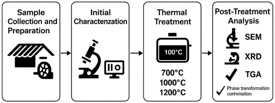
Figure 1.
Graphic scheme of the research workflow.
3.2. Initial Asbestos Content
The initial chrysotile content in the fiber cement samples was quantified using XRD with Rietveld refinement. The results are summarized in Table 1. Sample A contained 8.58 ± 0.45% chrysotile by mass, Sample B had 33.66 ± 1.12%, Sample C contained 11.60 ± 0.67%, and Sample D had 5.14 ± 0.33%. These values provide a baseline for evaluating the efficiency of thermal transformation processes.

Table 1.
Initial chrysotile content in fiber cement samples.
3.3. Particle Size Distribution
The particle size distribution of the milled powder samples (A–D) was analyzed to assess the homogeneity and fineness of the ground material. Table 2 summarizes the D10, D50, and D90 values for each sample. All samples exhibited a D50 value below 75 µm, confirming the suitability of the milling process for subsequent thermal treatment. The narrow range of particle sizes (D90–D10) indicates high homogeneity across samples.
Table 2.
Particle size distribution of milled powder samples.
3.4. SEM Analysis
3.4.1. Sample A
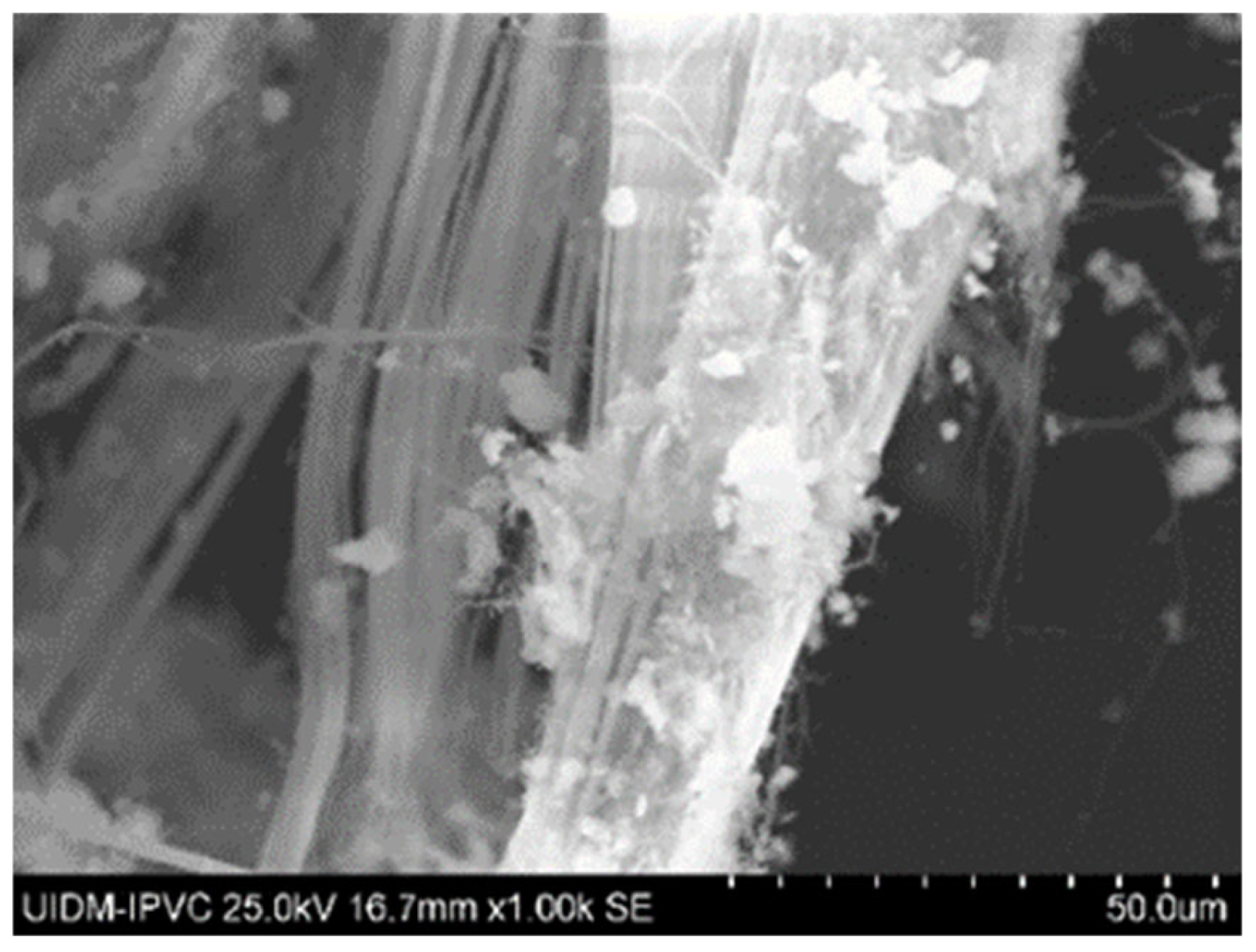
SEM images of Sample A (plate and powder) reveal the presence of fibrous asbestos structures. Figure 2 shows the microstructures of the plate sample, where asbestos fibers are clearly observed, forming interwoven fiber networks that enhance the mechanical properties of the material. Magnifications range from 100× to 5000×.
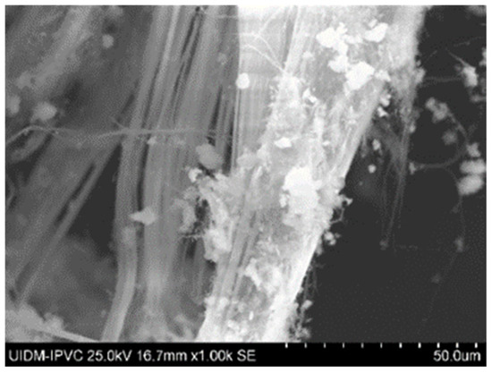
Figure 2.
Representative SEM image of Sample A plate at 1000× magnification, showing interwoven asbestos fiber networks. Additional SEM images are available in Supplementary Figures S1–S7.
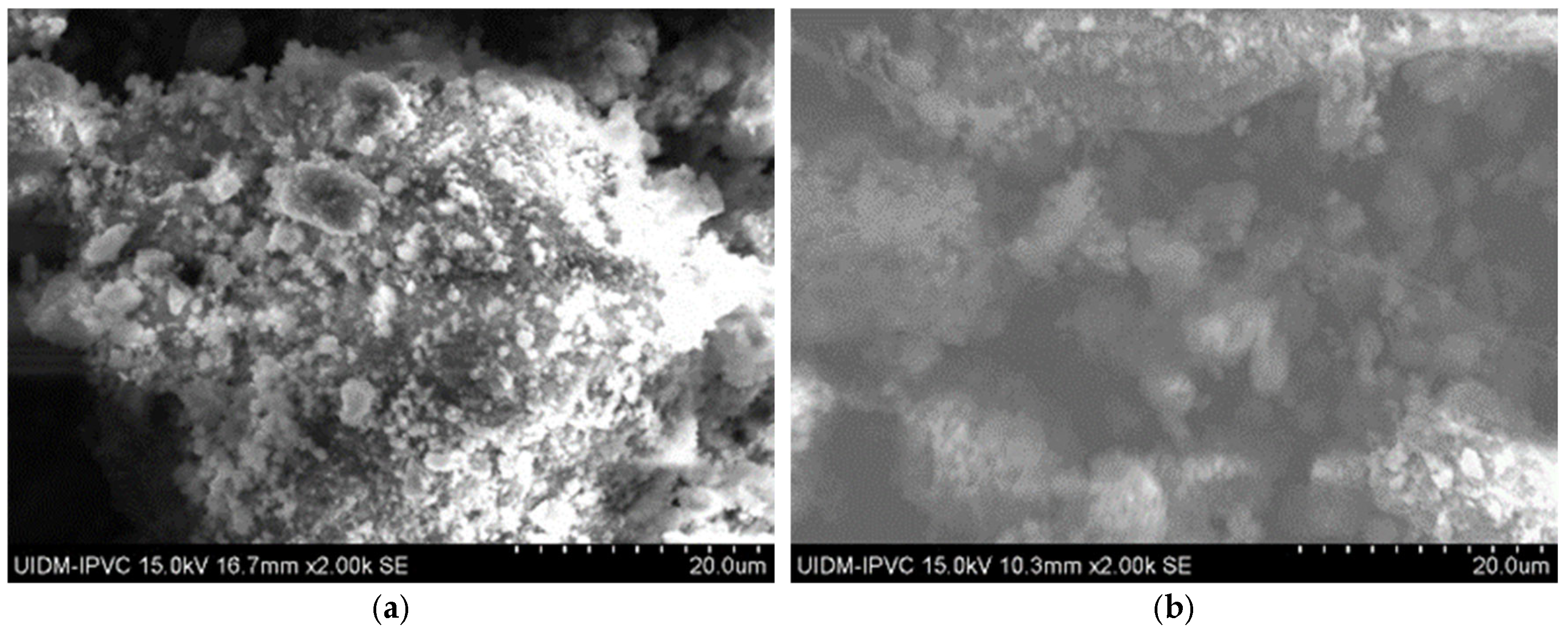
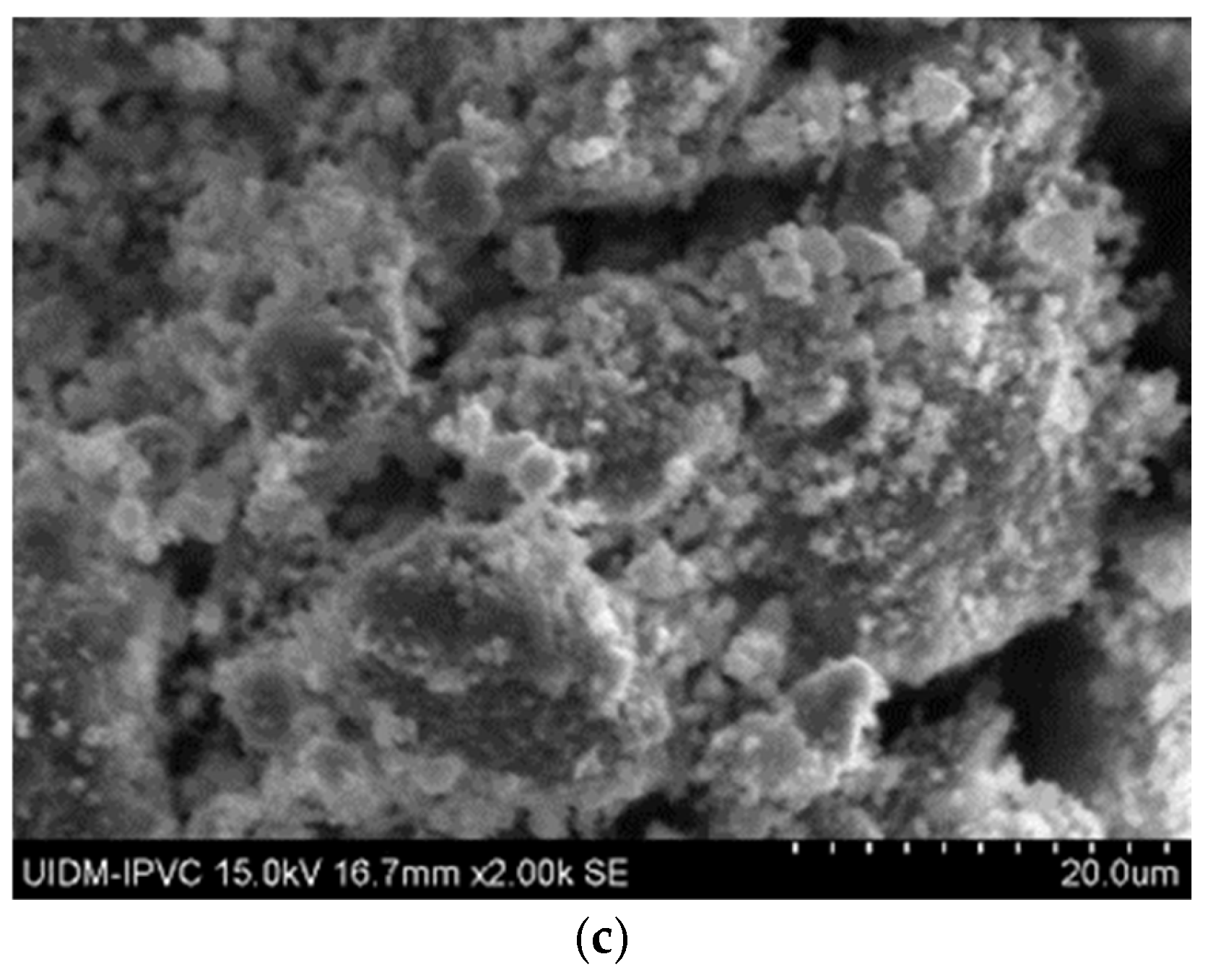
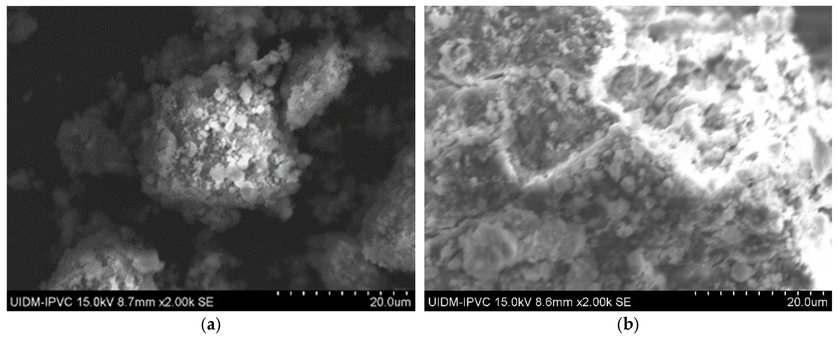
In contrast, SEM images of the powdered Sample A (Figure 3) do not clearly show asbestos fibers. However, this does not confirm their absence, as the fibers may have been pulverized to sizes below the SEM detection limit.
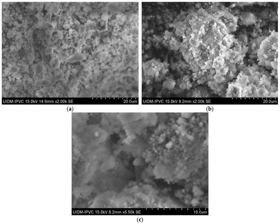
Figure 3.
(a) Sample A powder (2000× magnification); (b) Sample A powder (2000× magnification); and (c) Sample A powder (5500× magnification).
3.4.2. Sample B
SEM images of Sample B (plate) indicate a similar fibrous network (Figure 4), confirming the presence of asbestos. Images of the powdered sample do not clearly display fibers, raising uncertainty about the grinding process’s effectiveness in eliminating asbestos fibers.
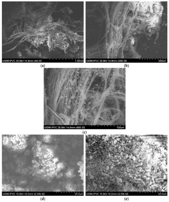
Figure 4.
(a) Sample B plate (50× magnification); (b) Sample B plate (200× magnification); (c) Sample B plate (500× magnification); (d) Sample B powder; and (e) Sample B powder.
3.4.3. Sample C
Sample C plate images (Figure 5) show a lower fiber concentration than Sample A, likely due to different manufacturing origins. Powdered Sample C images (Figure 4 and Figure 5) suggest that asbestos fibers might still be present in fragmented form.
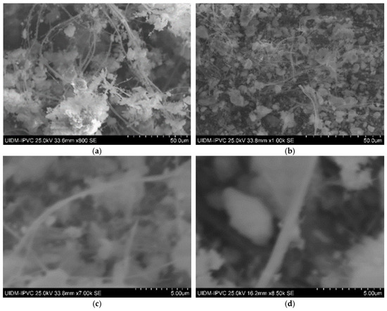
Figure 5.
(a,b) Sample C plate (various magnifications); and (c,d) Sample C powder.
In Figure 6, the microstructures of Sample C in powder form can be observed, with images captured at 2000× magnification. Once again, there is uncertainty as to whether grinding eliminates asbestos fibers, as some observations of these images suggest the presence of fiber remnants.
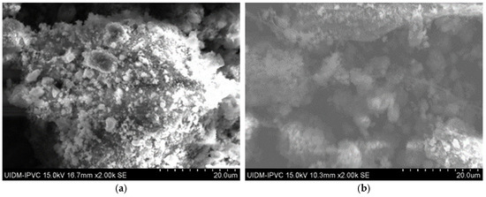
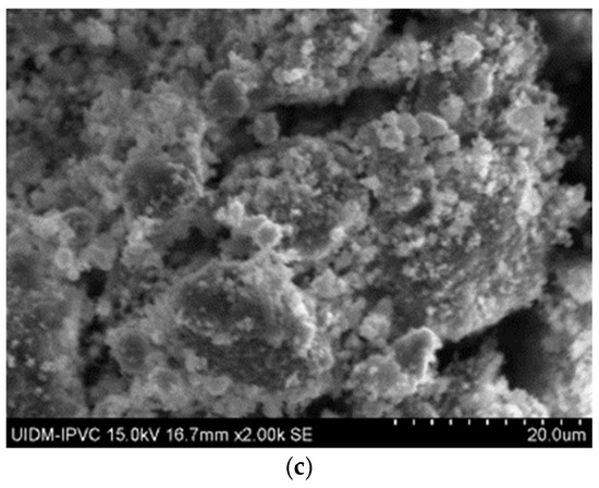
Figure 6.
(a–c) Sample C in powder form.
3.4.4. Sample D
Sample D plate images (Figure 7) confirm the abundant presence of asbestos fibers, forming an interconnected fiber network. The powdered sample images (Figure 8) do not show visible fibers, but their presence cannot be ruled out.
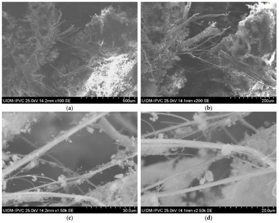
Figure 7.
(a–d) Sample D plate (various magnifications).
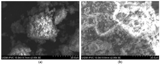
Figure 8.
(a,b) Sample D powder.
3.5. Thermogravimetric Analysis
TGA was conducted to confirm the decomposition of chrysotile in thermally treated samples. Untreated samples exhibited a mass loss of 12–14% between 600–800 °C, corresponding to chrysotile dehydroxylation, and an additional 20–25% loss between 800–900 °C due to carbonate decomposition. Samples treated at 700 °C showed partial dehydroxylation (4–6% mass loss), while those treated at 1000 °C and 1200 °C exhibited no mass loss in the 600–800 °C range, confirming complete chrysotile decomposition. These results corroborate the XRD findings of forsterite and enstatite formation. Post-treatment residues were analyzed using XRD to confirm the absence of chrysotile and the presence of forsterite and enstatite. No fibrous phases were detected in residues treated at 1000 °C or 1200 °C, which is consistent with the TGA results indicating complete decomposition.
3.6. SEM-EDS Analysis
3.6.1. Sample A
SEM-EDS analysis of Sample A (elemental quantification is detailed in Supplementary Figures S2–S9) identifies the elemental composition of the asbestos cement material. The analysis identified calcium (35.2 ± 1.1%), oxygen (40.8 ± 1.3%), silicon (15.6 ± 0.8%), magnesium (4.2 ± 0.4%), iron (2.1 ± 0.3%), aluminum (1.8 ± 0.2%), and sulfur (0.3 ± 0.1%) as primary elements.
3.6.2. Sample B
SEM-EDS analysis of Sample B (elemental quantification is detailed in Supplementary Figures S2–S9) reveals calcium (34.9 ± 1.0%), oxygen (41.2 ± 1.2%), silicon (14.8 ± 0.7%), magnesium (4.5 ± 0.5%), iron (2.0 ± 0.3%), aluminum (1.7 ± 0.2%), fluorine (0.4 ± 0.1%), and antimony (0.2 ± 0.1%).
3.6.3. Sample C
The elemental composition of Sample C powder (elemental quantification is detailed in Supplementary Figures S2–S9) contained calcium (36.1 ± 1.2%), oxygen (39.7 ± 1.1%), and silicon (16.3 ± 0.9%), which is consistent with other samples.
3.6.4. Sample D
SEM-EDS analysis of Sample D (elemental quantification is detailed in Supplementary Figures S2–S9) exhibited calcium (35.5 ± 1.1%), oxygen (40.3 ± 1.2%), silicon (15.9 ± 0.8%), and minor elements, with no significant deviations from other samples.
3.7. XRD Analysis
3.7.1. Sample A
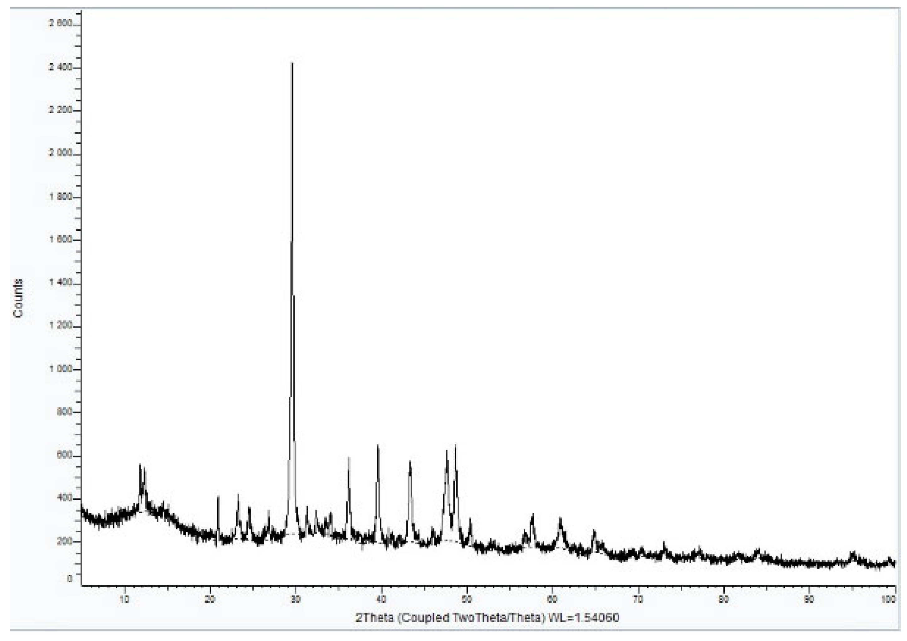
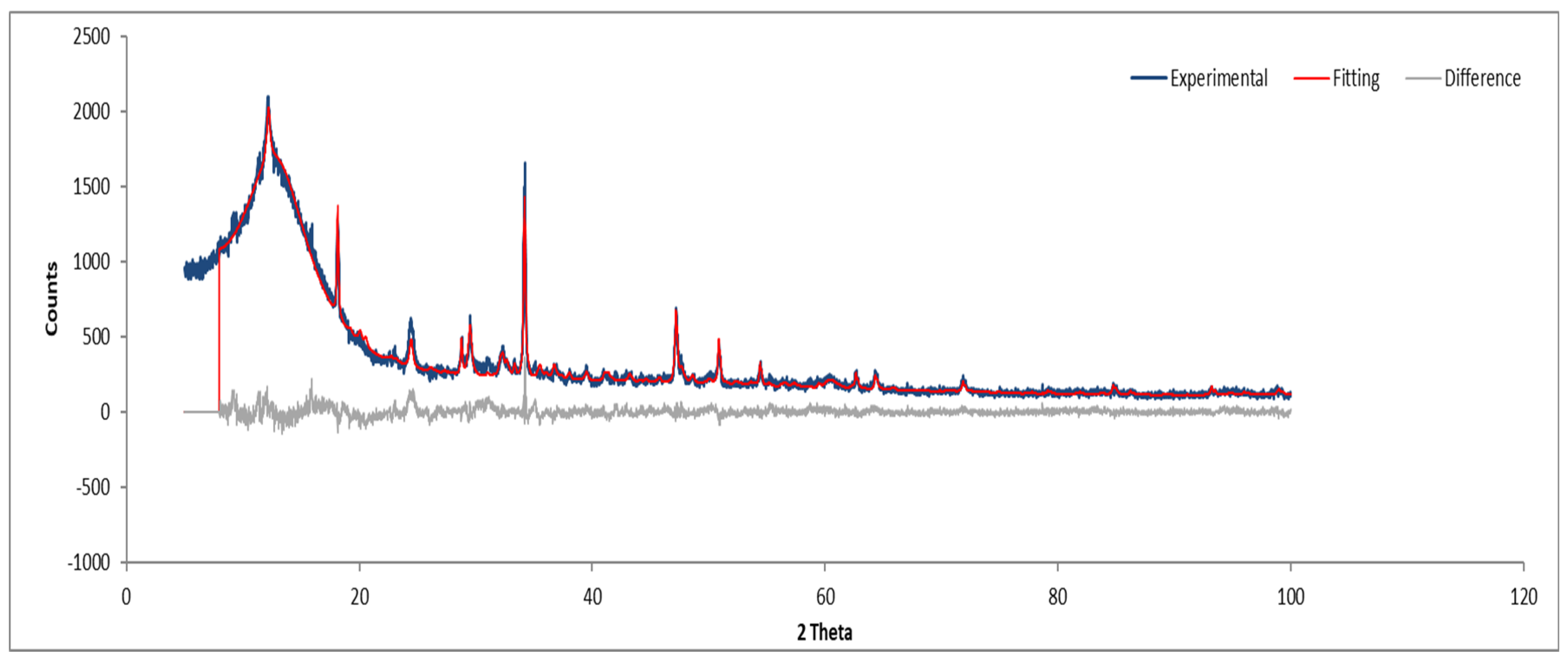
XRD analysis of Sample A (Figure 9, Figure 10 and Figure 11) identifies key crystalline phases, including C2S (β-larnite), C3S (alite M1), C4AF (calcium aluminum iron oxide), and clinochrysotile, the latter being characteristic of asbestos.
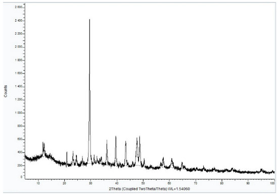
Figure 9.
XRD diffractogram of Sample A plate.
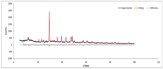
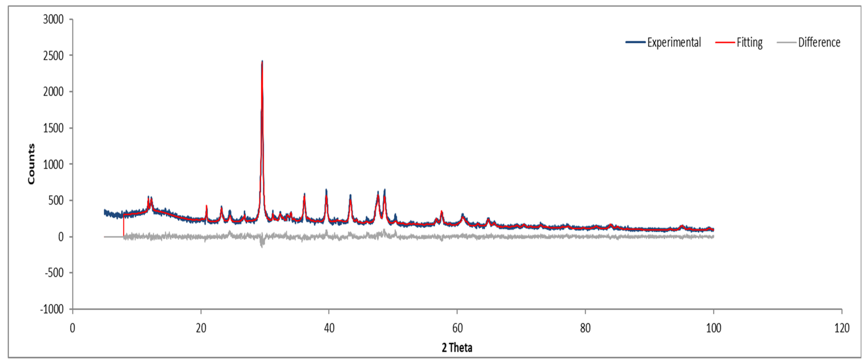
Figure 10.
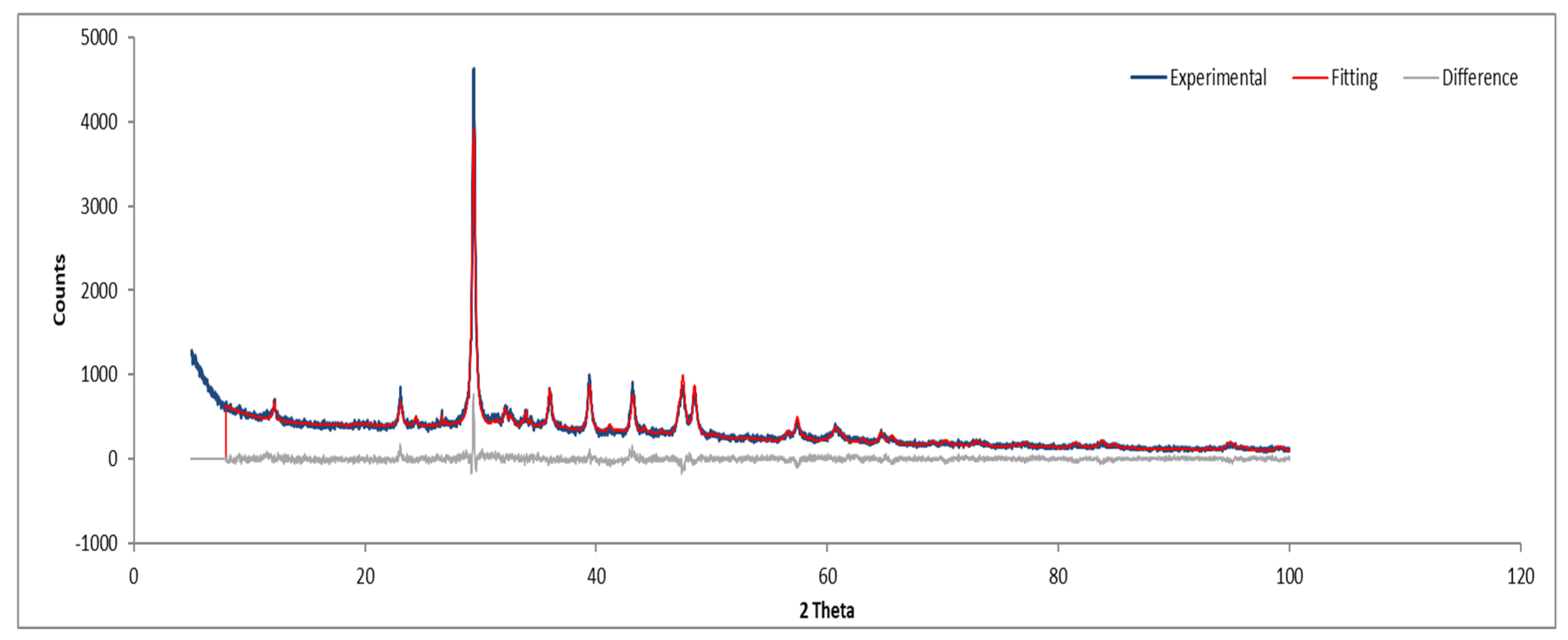
XRD diffractogram with Rietveld refinement (Sample A plate).

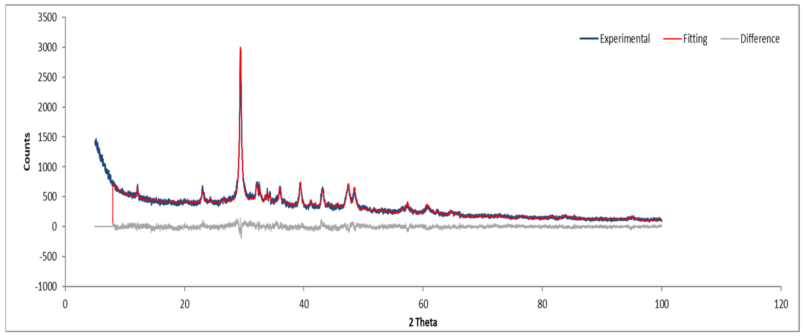
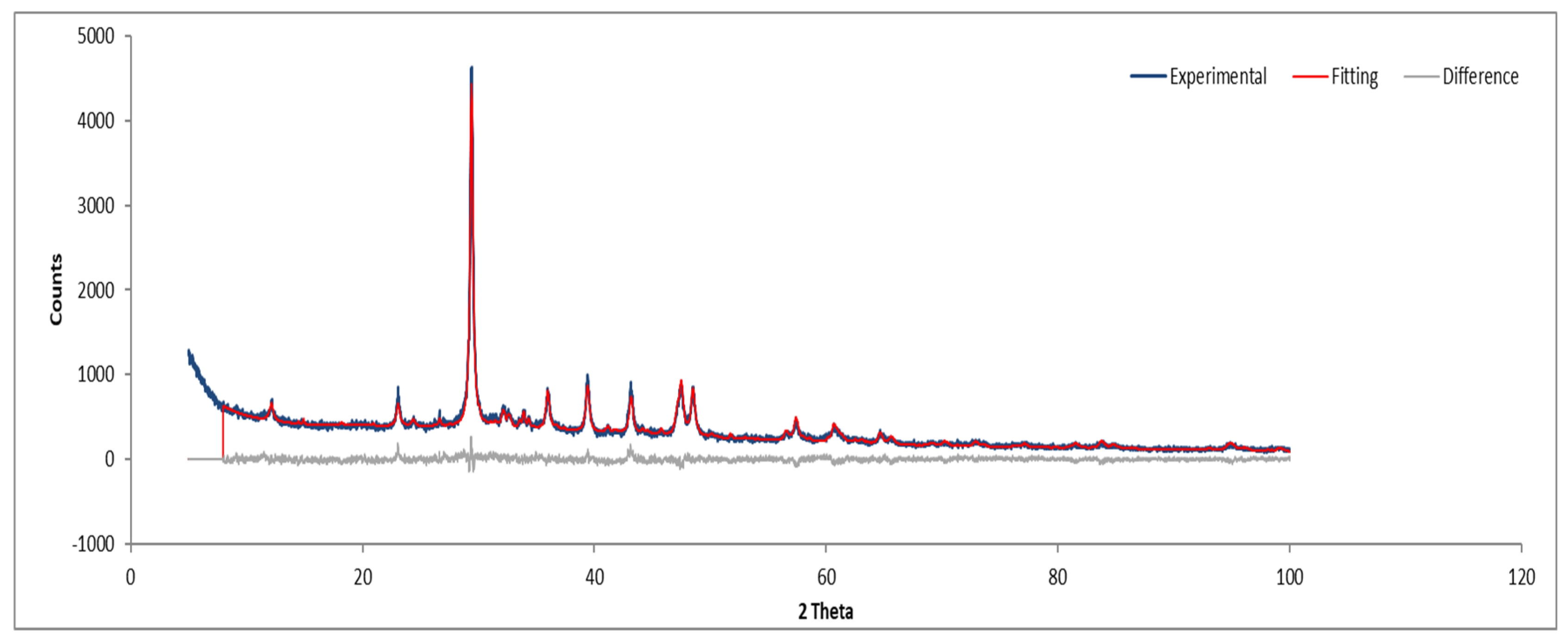
Figure 11.
XRD diffractogram with Rietveld refinement (Sample A powder).
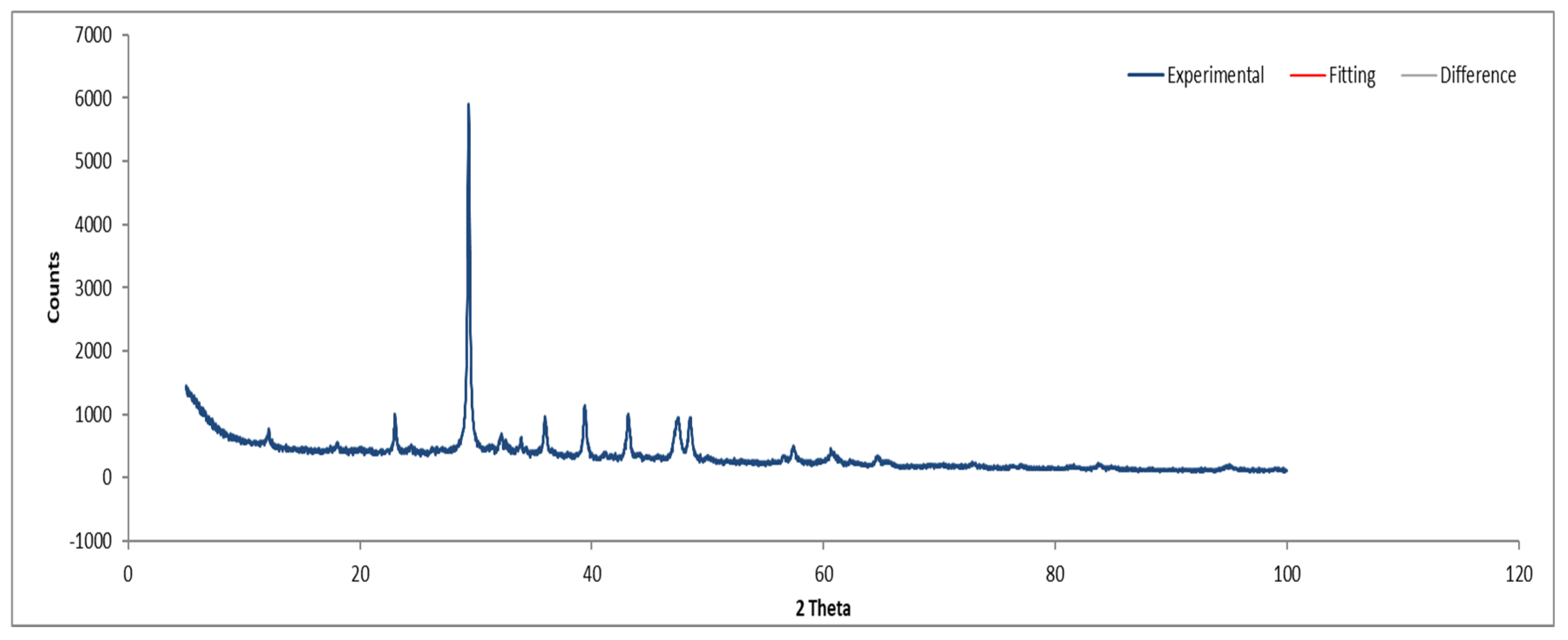
3.7.2. Sample B
Figure 12 and Figure 13 show the XRD analysis for Sample B, with the identified phases summarized in Table 1.
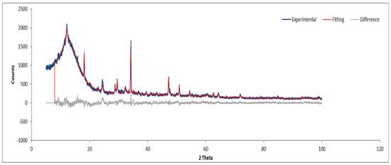
Figure 12.
XRD diffractogram of Sample B plate.
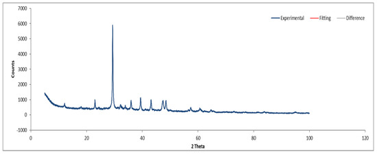
Figure 13.
XRD diffractogram of Sample B powder.
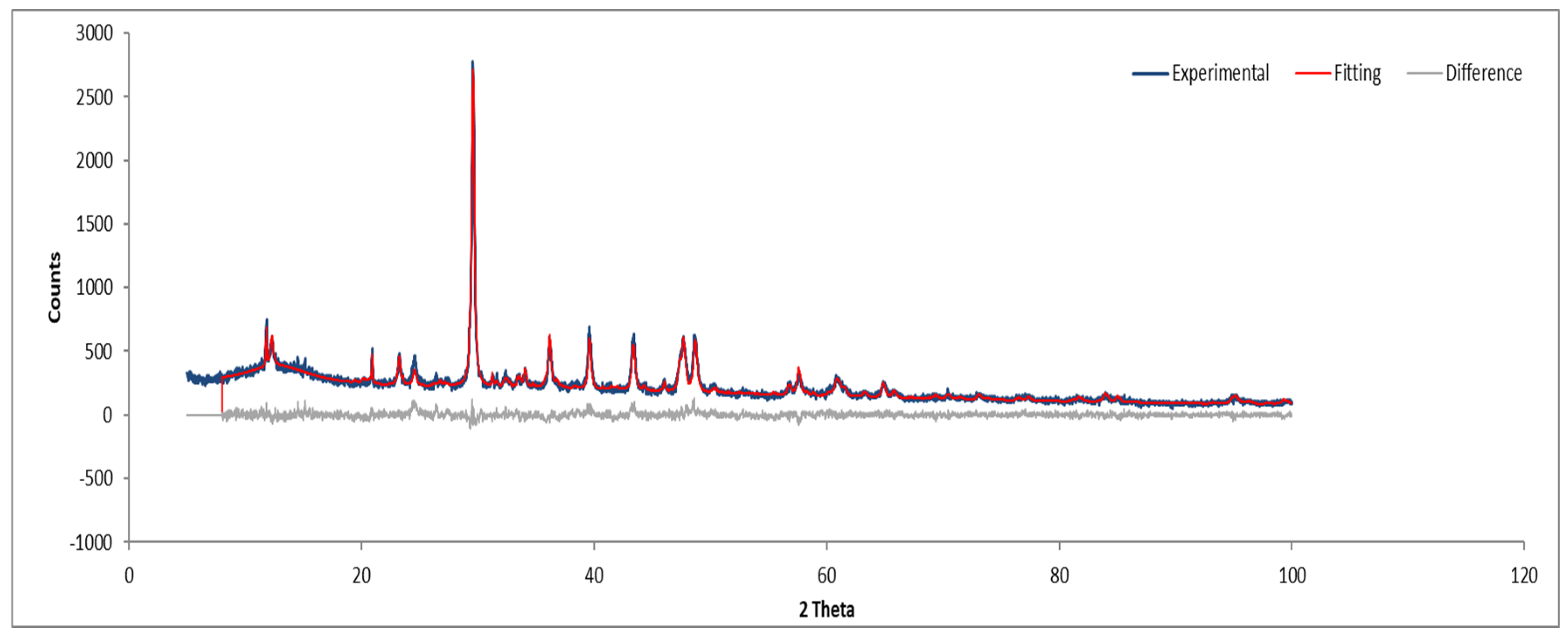
3.7.3. Sample C
Figure 14 and Figure 15 depict the XRD results for Sample C, which are consistent with the previously identified phases.
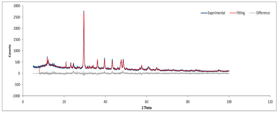
Figure 14.
XRD diffractogram of Sample C plate.
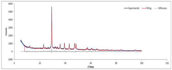
Figure 15.
XRD diffractogram of Sample C powder.
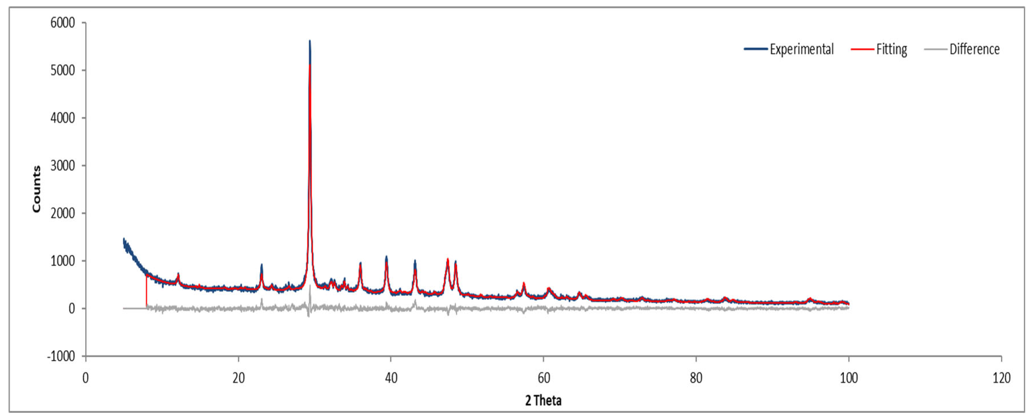
3.7.4. Sample D
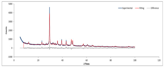
Figure 16.
XRD diffractogram of Sample D plate.
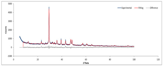
Figure 17.
XRD diffractogram of Sample D powder.
3.7.5. Summary of XRD Analysis
A comparative summary of the identified crystalline phases is presented in Table 3, demonstrating the consistency of the detected mineral phases across all samples.
Table 3.
Summary of crystalline phases identified in XRD analysis (mean ± standard deviation).
4. Discussion
The thermal treatment of ACMs has garnered significant attention due to its ability to transform hazardous fibrous minerals into non-fibrous, stable phases suitable for use in cement or mineral wool production. This study synthesizes findings from experimental analyses with recent literature, providing a comparative analysis of thermal effects on asbestos mineral transformation, its implications for material recycling, and its integration into circular economy models. The results revealed that temperatures above 700 °C initiate significant changes in asbestos fibers, while complete transformation into non-fibrous, stable phases occurs at temperatures of approximately 1000 °C or higher. This aligns with findings by Bloise (2019), who demonstrated that actinolite asbestos undergoes thermal decomposition at approximately 1030 °C, resulting in recrystallization into stable crystalline phases while preserving fibrous morphology as pseudomorphs [8].
The use of TGA complemented XRD analysis by confirming the absence of chrysotile-related mass loss in samples treated at 1000 °C and 1200 °C, enhancing confidence in the complete decomposition of asbestos fibers. While XRD alone may not detect trace chrysotile due to its detection limit (approximately 1% by mass), the absence of dehydroxylation in TGA suggests that residual chrysotile, if present, is below biologically significant levels. The selection of 700 °C, 1000 °C, and 1200 °C for thermal treatment was validated by TGA data, which confirmed progressive chrysotile decomposition and phase transformation. These temperatures effectively addressed the variability in fiber cement compositions, ensuring robust detoxification across all samples.
The inability of SEM-EDS to detect ultrafine fibers (<0.5 µm) suggests that future studies should incorporate transmission electron microscopy (TEM) to confirm the absence of nanoscale asbestos remnants, particularly in powdered samples. This would enhance the robustness of morphological analyses and ensure comprehensive safety assessments.
The transformation of chrysotile (Mg3Si2O5(OH)4) into forsterite (Mg2SiO4) and enstatite (MgSiO3) under heat treatment was particularly evident in this study. Iwaszko (2019) found similar results, reporting that calcite decomposes into calcium oxide (CaO) and chrysotile transitions into forsterite and enstatite at 700 °C, with complete loss of fibrous morphology at 1300 °C [9]. This transformation highlights the efficacy of thermal treatment in detoxifying asbestos materials, making them safer for reuse.
The transformation of chrysotile into forsterite and enstatite aligns with findings by Bloise et al. (2017), who detailed the thermal behavior of mineral fibers, noting that chrysotile begins to lose its hydroxyl groups above 600 °C, with complete recrystallization into stable phases by 1000 °C [12]. Additionally, Bloise et al. (2017) demonstrated that mechanical grinding prior to thermal treatment can alter the crystalline structures of chrysotile, amosite, and crocidolite, potentially enhancing the efficiency of subsequent heat-induced phase changes [12]. These complementary effects of grinding and thermal treatment observed in our study suggest a synergistic approach to asbestos inertization.
The incorporation of thermally treated ACMs into cement production has been extensively studied. Kusiorowski et al. (2024) demonstrated that thermal treatment converts asbestos fibers into phases like belite (C2S) and alite (C3S), which are integral to cement clinker production. Their work emphasizes the dual benefits of reducing hazardous waste and enhancing material properties in cement applications [13].
Carneiro et al. (2021) optimized the calcination process for asbestos cement waste (ACW), achieving complete dehydroxylation of chrysotile at 800 °C and producing a material with 40.42% belite content, which provides binding capacity comparable to traditional cements [14]. The findings of the current study align with these results, confirming the potential of thermally treated asbestos to contribute to sustainable cement manufacturing.
The use of thermally treated ACMs in mineral wool production has emerged as a viable alternative for material recycling. Wentao et al. (2019) demonstrated that pre-firing asbestos at 700 °C for 1 h transformed chrysotile into forsterite, which subsequently formed intertwined spherulitic structures during sintering at 1200 °C. The resulting glass–ceramics exhibited enhanced mechanical strength and durability, meeting construction standards [15].
The current study corroborates these findings, as thermal treatment resulted in the formation of non-fibrous phases suitable for mineral wool production. This transformation not only reduces landfill demand but also aligns with circular economy principles by reintegrating waste materials into high-value applications.
While thermal treatment effectively eliminates the fibrous morphology of asbestos, some studies suggest residual concerns. Ballirano et al. (2020) highlighted that thermally treated asbestos may retain surface reactivity, specifically oxygen-centered radicals like hydroxyl groups, which could pose potential health risks if not adequately managed [16]. The findings of this study suggest that incorporating treated asbestos into stable matrices, such as cement or mineral wool, can mitigate these risks effectively.
Hydrothermal treatments have also been proposed as alternatives to thermal processes. Spasiano et al. (2019) showed that hydrothermal conditions combined with acidic solutions can degrade chrysotile fibers and convert them into inert phases like forsterite and enstatite [17]. However, these methods often require specialized equipment and longer processing times compared to thermal treatment.
The current study reinforces the efficiency of thermal treatment as a practical and scalable solution for asbestos detoxification, particularly when combined with downstream recycling processes.
The integration of thermally treated ACMs into industrial processes, such as cement and mineral wool production, offers significant environmental benefits by reducing landfill waste and minimizing raw material extraction. Ruiz et al. (2018) emphasized that these approaches align with the principles of the circular economy, transforming hazardous waste into secondary raw materials suitable for industrial use [3].
Economically, the reuse of treated asbestos can reduce disposal costs and create new revenue streams through the production of high-value materials, such as eco-friendly cement and advanced insulation products. These benefits underline the importance of developing policies and infrastructure to support the adoption of thermal treatment technologies.
Scaling this thermal inertization process to an industrial level presents both opportunities and challenges. Industrially, large-scale rotary kilns or fluidized bed reactors, commonly used in cement production, could adapt to treat asbestos-containing waste, processing tons of material daily compared to the gram-scale laboratory experiments reported here. Successfully treated materials, such as forsterite- and enstatite-rich powders, could be directly incorporated into cement clinker or melted into mineral wool, offering durable, high-value products that meet construction standards [15]. However, implementation requires significant upfront investment in furnace infrastructure and emission control systems to manage volatile byproducts like water vapor and trace gases released during chrysotile decomposition. A preliminary cost estimate suggests that thermal treatment could range from EUR 150–300 per ton of asbestos waste, factoring in energy costs (approximately 1.5–2 MWh/ton at EUR 100/MWh), equipment amortization, and labor, though this could be offset by savings on landfill fees (typically EUR100–200/ton in Europe) and revenue from selling recycled materials (e.g., EUR 50–100/ton for cement additives). Further pilot-scale studies are needed to refine these estimates and assess long-term material performance in real-world applications.
5. Conclusions
This study confirmed the effectiveness of heat treatment in transforming asbestos-containing materials (ACM) into stable, non-fibrous mineral phases, providing a viable solution for the safe and sustainable management of hazardous waste. Analysis of the samples demonstrated that temperatures above 700 °C are sufficient to initiate the decomposition of asbestos minerals, with complete elimination of the fibrous morphology observed at temperatures above 1000 °C. The results obtained by X-ray diffraction (XRD) and scanning electron microscopy with energy dispersive spectroscopy (SEM-EDS) confirmed the phase transition as chrysotile to forsterite and enstatite, as well as the decomposition of calcite into calcium oxide (CaO), creating new stable and inert matrices. Furthermore, it was observed that grinding the samples significantly reduced the particle size, but did not eliminate the fibers, reinforcing the need for heat treatments to ensure the total neutralization of the associated risk. The integration of treated MCA into industrial processes, such as cement and mineral wool production, has been widely validated. Cement production with treated waste has shown promising results, with the presence of phases such as belite (C2S) and alite (C3S), improving the material’s performance and promoting sustainability by replacing conventional raw materials. Likewise, the transformation of waste into mineral wool and advanced ceramics has shown technical feasibility, with resulting products of high quality and added value. Despite advances, this work also highlighted challenges. Although heat treatment eliminates the fibrous morphology, studies indicate that residual surface reactivity may persist under certain conditions. Therefore, it is necessary to further investigate the chemical reactivity and possible toxic impacts of the by-products generated, ensuring total environmental and occupational safety. Additionally, process optimization, such as the integration of hybrid technologies that combine thermal and hydrothermal treatments, can increase efficiency and reduce costs. The way forward includes the industrial scale of the proposed technologies, combined with public policies that encourage the recycling of waste containing asbestos. This study reinforces the potential of thermal treatment as a central pillar of a circular economy model, transforming hazardous waste into valuable resources and contributing to the reduction of the global environmental footprint. The continuation of this research could consolidate innovative and sustainable solutions for MCA management in different industrial contexts.
Supplementary Materials
The following supporting information can be downloaded at: https://www.mdpi.com/article/10.3390/fib13050062/s1, Figure S1. (a) Sample A (100x magnification); (b) Sample A (200x magnification); (c) Sample A (1000x magnification); (d) Sample A (1400x magnification); and (e) Sample A (5000x magnification). Figure S2. (a) to (j) SEM-EDS images of Sample A plate (elemental distribution). Figure S3. (a) to (h) SEM-EDS images of Sample A powder. Figure S4. EDS spectrum and elemental quantification of Sample A powder. Figure S5. (a) to (j) SEM-EDS images of Sample B plate and powder. Figure S6. EDS spectrum and elemental quantification of Sample B plate. Figure S7. EDS spectrum and elemental quantification of Sample B powder. Figure S8. EDS spectrum and elemental quantification of Sample C powder. Figure S9. EDS spectrum and elemental quantification of Sample D powder.
Author Contributions
Conceptualization, A.C. (António Curado) and L.J.R.N.; Methodology, A.C. (António Curado) and L.J.R.N.; Validation, A.C. (António Curado) and L.J.R.N.; Formal analysis, A.C. (António Curado) and L.J.R.N.; Investigation, A.C. (António Curado), L.J.R.N., A.C. (Arlete Carvalho), J.A., E.L. and M.T.; Resources, A.C. (António Curado); Data curation, A.C. (António Curado) and L.J.R.N.; Writing—original draft, A.C. (António Curado) and L.J.R.N.; Writing—review & editing, A.C. (António Curado) and L.J.R.N.; Project administration, A.C. (António Curado). All authors have read and agreed to the published version of the manuscript.
Funding
This work is the result of the project FiberRec—Recovery of End-of-Life Construction Materials: Fiber Processing from a Circular Economy Perspective, Project No. 2022.09272. PTDC, whose funding was approved by FCT, I.P. All researchers were supported by proMetheus, Research Unit on Energy, Materials and Environment for Sustainability—UIDP/05975/2020, funded by national funds through FCT—Fundação para a Ciência e Tecnologia. António Curado was financed by national funds through the FCT/MCTES.
Data Availability Statement
Data are available upon request to the corresponding author.
Acknowledgments
The authors thank FCT and I.P. for the opportunity to provide funding for research.
Conflicts of Interest
The authors declare no conflicts of interest.
References
- Paolini, V.; Tomassoli, E.; Segreto, M. Advances in asbestos waste management: A review of recycling and reuse strategies. Waste Manag. 2023, 171, 234–245. [Google Scholar] [CrossRef]
- Ginga, C.P.; Ongpeng, J.M.C.; Daly, M. Circular economy in construction: A systematic review of sustainable practices. Sustainability 2023, 15, 3289. [Google Scholar] [CrossRef]
- Ruiz, L.; Ramón, X.; Domingo, S. The circular economy in the construction and demolition waste sector—A review and an integrative model approach. J. Clean. Prod. 2020, 248, 119238. [Google Scholar] [CrossRef]
- Gualtieri, A.F.; Foresti, E.; Vanni, M. Recycling of asbestos-containing materials into mineral wool: A sustainable approach. J. Hazard. Mater. 2022, 424, 127512. [Google Scholar] [CrossRef]
- Norouzi, M.; Chàfer, M.; Cabeza, L.; Jiménez, L.; Boer, D. Circular economy in the building and construction sector: A scientific evolution analysis. J. Build. Eng. 2021, 44, 102704. [Google Scholar] [CrossRef]
- Lahondère, D.; Wille, G.; Schmidt, U.; Silvent, J.; Duron, J.; Duée, C. Morphological and Chemical Characterization of Asbestos Fibers in Solid Rocks: Towards an In-Situ and Combined Analytical Approach. In Proceedings of the EGU General Assembly, Vienna, Austria, 4–8 May 2020; EGU2020-13773. [Google Scholar] [CrossRef]
- Cline, J.; Von, R.; Winburn, R.; Stephens, P.; Filliben, J. Addressing the Amorphous Content Issue in Quantitative Phase Analysis: The Certification of NIST SRM 676a. J. Appl. Crystallogr. 2011, A67, 357–367. [Google Scholar] [CrossRef]
- Bloise, A. Thermal behaviour of actinolite asbestos. J. Mater. Sci. 2019, 54, 11784–11795. [Google Scholar] [CrossRef]
- Iwaszko, J. Making asbestos-cement products safe using heat treatment. Case Stud. Constr. Mater. 2019, 10, e00221. [Google Scholar] [CrossRef]
- Valdré, S.; Poggi, G.; Buccola, A.; Casini, G.; Le Neindre, N.; Alba, R.; Barlini, S.; Bini, M.; Boiano, A.; Bonnet, E.; et al. Time of flight identification with FAZIA. In Proceedings of the International Workshop on Multi facets of EoS and Clustering (IWM-EC 2018), Catane, Italy, 22–25 May 2018; p. 167. [Google Scholar] [CrossRef]
- Directive 2008/98/EC of the European Parliament and of the Council on Waste (C(2012) 2384 Final). Available online: https://eur-lex.europa.eu/eli/dir/2008/98/oj/eng (accessed on 10 February 2025).
- Bloise, A.; Kusiorowski, R.; Gualtieri, M.; Gualtieri, A. Thermal Behaviour of Mineral Fibres; The Mineralogical Society of Great Britain & Ireland: Middlesex, UK, 2017. [Google Scholar] [CrossRef]
- Kusiorowski, R.; Gerle, A.; Kujawa, M.; Śliwa, A.; Adamek, J. Characterisation of asbestos-containing wastes by thermal analysis. J. Therm. Anal. Calorim. 2024, 149, 10681–10694. [Google Scholar] [CrossRef]
- Carneiro, G.; Santos, T.; Simonelli, G.; Ribeiro, D.; Cilla, M.; Dias, C. Thermal treatment optimization of asbestos cement waste (ACW) potentializing its use as alternative binder. J. Clean. Prod. 2021, 320, 128801. [Google Scholar] [CrossRef]
- Wentao, H.; Jian, X.; Ran, L.; Zhao, X.; Qiu, L.; Yang, W. Developing superhydrophobic rock wool for high-viscosity oil/water separation. Chem. Eng. J. 2019, 368, 837–846. [Google Scholar] [CrossRef]
- Ballirano, P.; Pacella, A. Towards a detailed comprehension of the inertisation processes of amphibole asbestos: In situ high-temperature behaviour of fibrous tremolite. Mineral. Mag. 2020, 84, 888–899. [Google Scholar] [CrossRef]
- Spasiano, D.; Luongo, V.; Race, M.; Petrella, A.; Fiore, S.; Apollonio, C.; Pirozzi, F.; Fratino, U.; Piccinni, A. Sustainable bio-hydrothermal sequencing treatment for asbestos-cement wastes. J. Hazard. Mater. 2019, 364, 256–263. [Google Scholar] [CrossRef] [PubMed]


Disclaimer/Publisher’s Note: The statements, opinions and data contained in all publications are solely those of the individual author(s) and contributor(s) and not of MDPI and/or the editor(s). MDPI and/or the editor(s) disclaim responsibility for any injury to people or property resulting from any ideas, methods, instructions or products referred to in the content. |
© 2025 by the authors. Licensee MDPI, Basel, Switzerland. This article is an open access article distributed under the terms and conditions of the Creative Commons Attribution (CC BY) license (https://creativecommons.org/licenses/by/4.0/).