Article

Durable Hydrophilic PVDF Hollow Fiber Membrane for Dissolved Organics Separation from High-Salinity Produced Water

1
Department of Civil and Environmental Engineering, New Mexico Institute of Mining and Technology, Socorro, NM 87801, USA
2
Petroleum Recovery Research Center, New Mexico Institute of Mining and Technology, Socorro, NM 87801, USA
3
Department of Materials Engineering, New Mexico Institute of Mining and Technology, Socorro, NM 87801, USA
4
Department of Chemical Engineering, New Mexico Institute of Mining and Technology, Socorro, NM 87801, USA
*
Author to whom correspondence should be addressed.
Fibers 2025, 13(3), 31; https://doi.org/10.3390/fib13030031
Submission received: 1 February 2025 / Revised: 24 February 2025 / Accepted: 10 March 2025 / Published: 11 March 2025

Abstract

:

Highlights

What are the main findings?
  • Durable hydrophilic PVDF hollow fiber membranes were formulated and fabricated with lithium chloride (LiCl) and polyvinylpyrrolidone (PVP) as synergistic pore agents.
  • The hydrophilic PVDF hollow fiber membrane showed a double-skinned macrovoids-free structure.
What is the implication of the main finding?
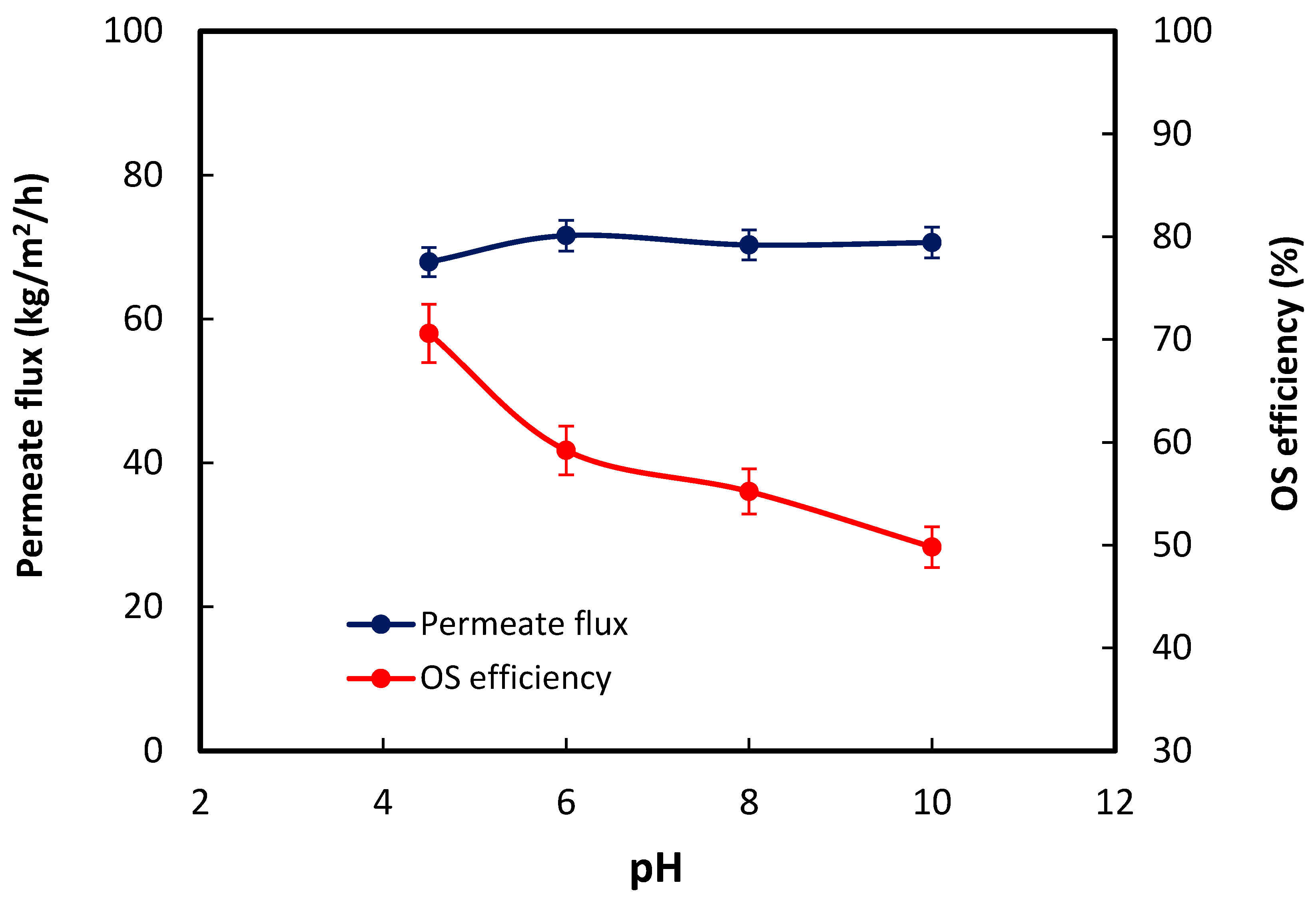
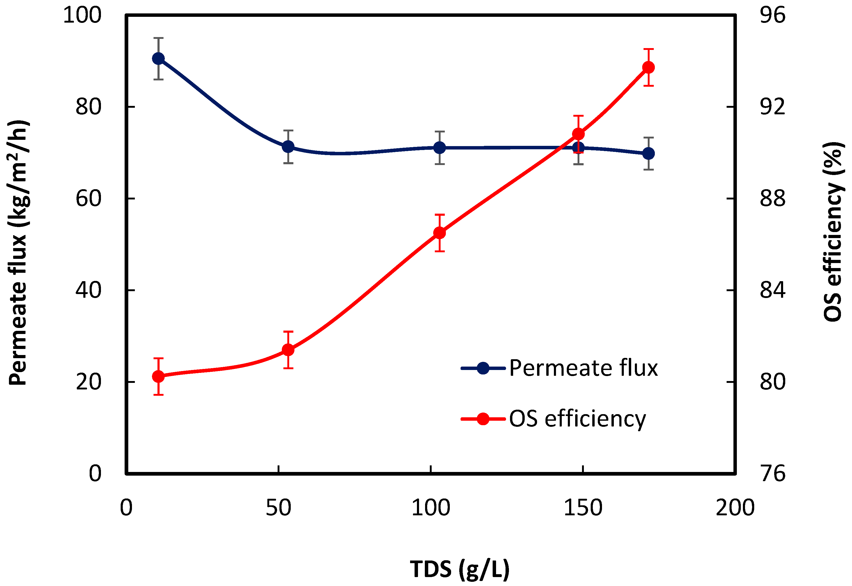
  • Both produced water salinity and pH affected the organics removal efficiency.
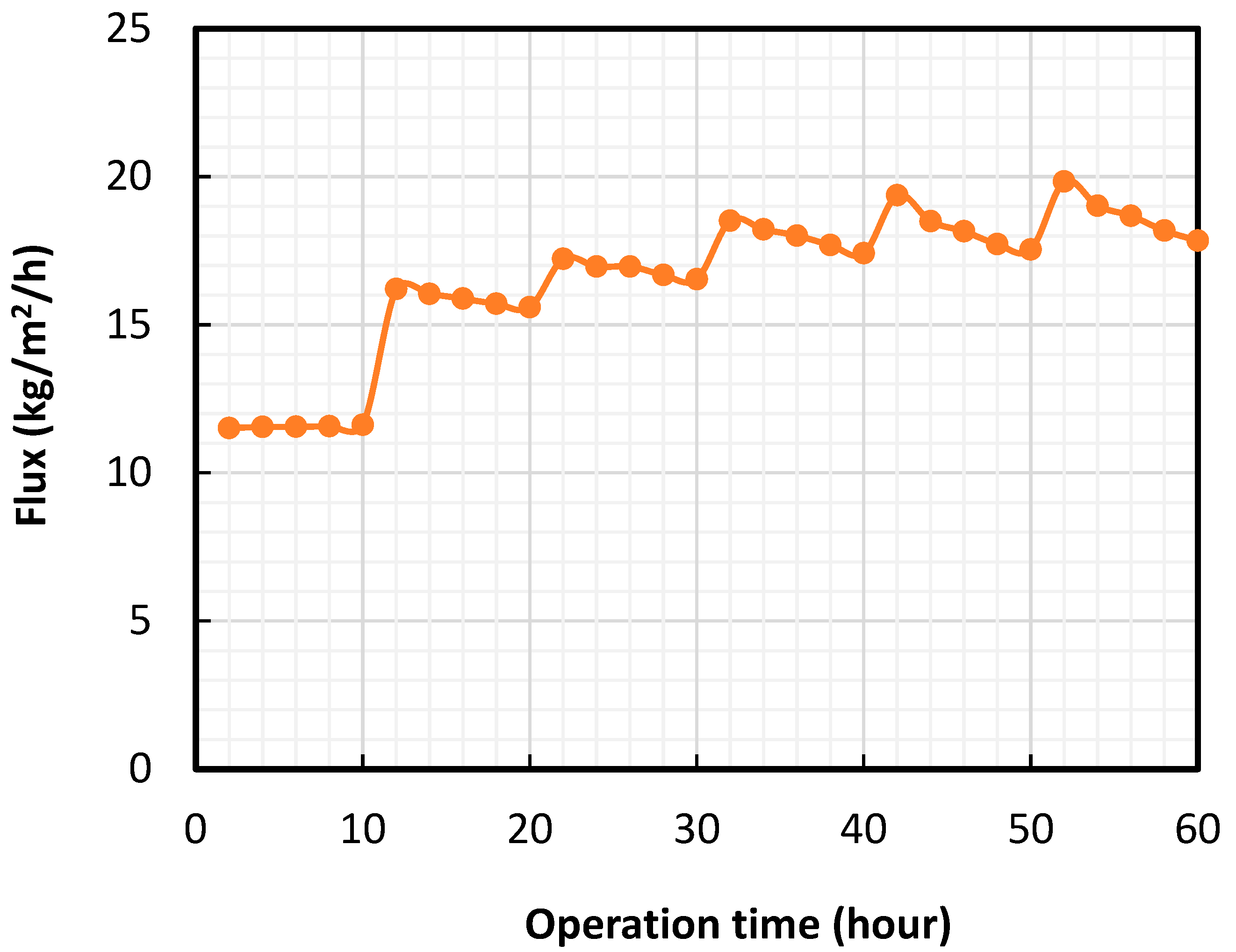
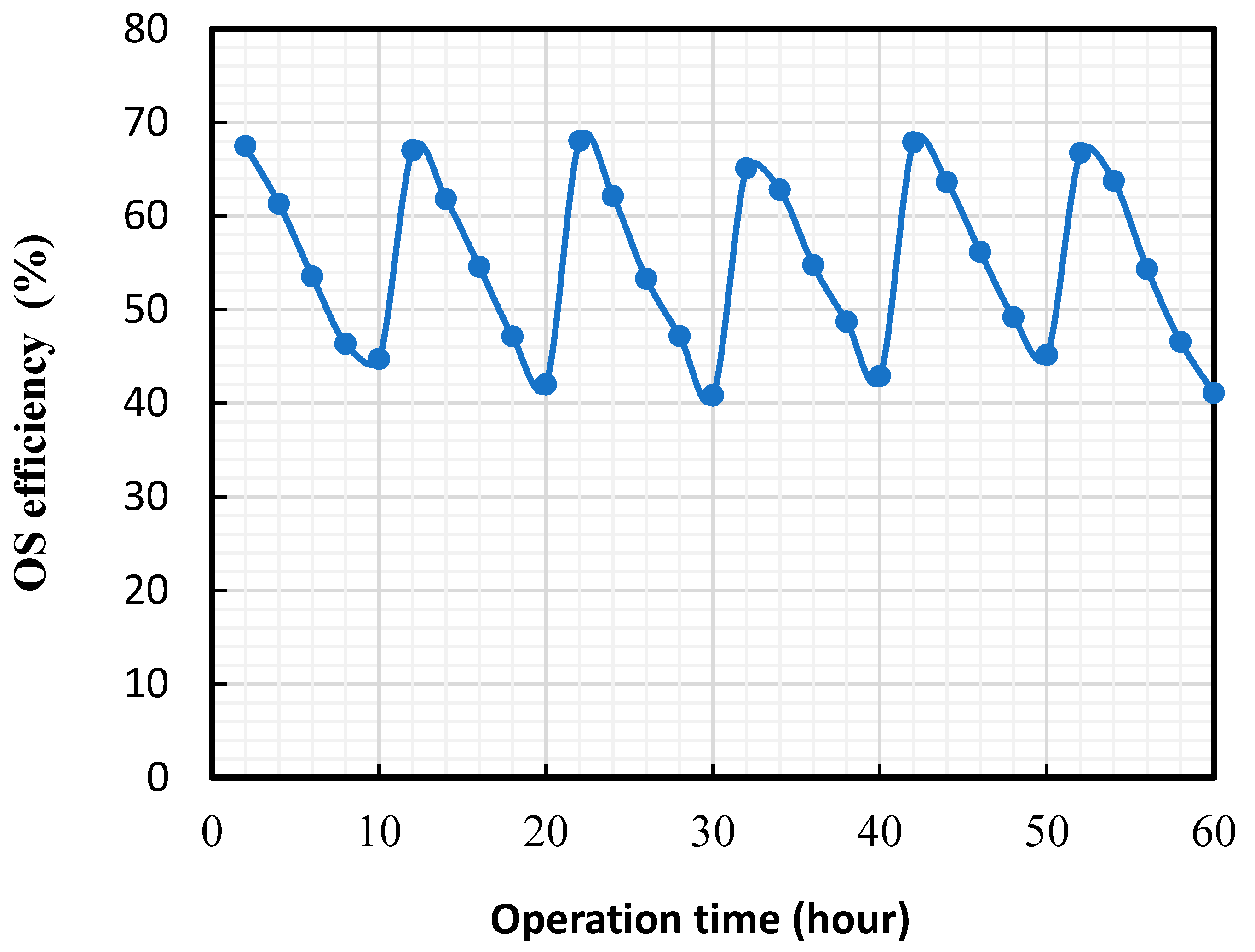
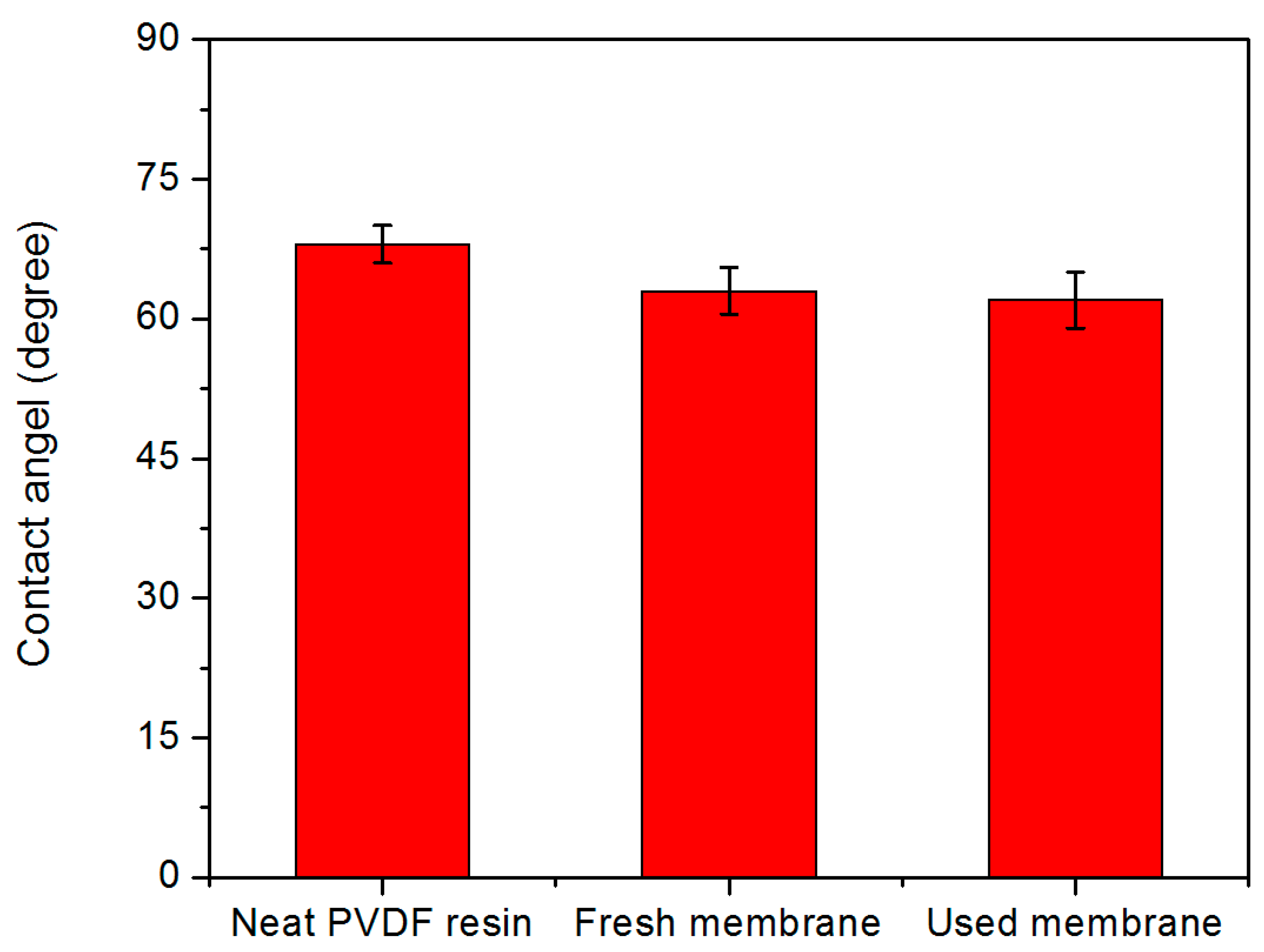
  • The membrane showed a near-100% recovery of organics separation efficiency due to consistent membrane hydrophilicity.
  • The results provided a portable and durable strategy for organic separation from high-salinity produced water.

Abstract

Organic compounds are major constituents in produced water that have gained increasing attention due to their negative impacts on operations and the environment. In this study, a novel hydrophilic polyvinylidene fluoride (PVDF) hollow fiber (HF) membrane was formulated and fabricated for organics separation (OS) from oilfield-produced water. The PVDF dope solution was formulated with lithium chloride (LiCl) and polyvinylpyrrolidone (PVP) as synergistic pore agents, and the obtained PVDF HF membranes showed a defect-free asymmetric structure with a stable hydrophilicity. The OS performance was studied in terms of permeate water flux, OS efficiency, and long-term membrane stability using both decanoic acid and real produced water as feed solutions. Specifically, the effects of operating parameters, such as pressure, total organic carbon (TOC), pH, and salinity, on the OS performance were examined in decanoic acid solution. The long-term membrane stability was evaluated through a 60 h continuous OS experiment using real produced water as the feed solution. The used membrane was thoroughly characterized to understand both scaling and fouling phenomena during the OS operation. The results indicated that the membranes showed promising permeate water flux (>500 kg/m2/h at 350 kPa) and OS efficiency (>92%). It also exhibited a near-100% recovery of organics separation efficiency during six cyclic OS experiments due to consistent membrane hydrophilicity.

1. Introduction

The global population increase and industrialization have led to high energy demands from oil and gas. Oil and gas operations generate large volumes of water (called produced water). During conventional oil production, the co-produced water could reach 10 barrels per each barrel of oil depending on conditions such as geological characteristics, type, and age of the formation (older reservoirs generate higher volumes) [1]. The cost of produced water discharge per barrel of oil and gas, and the negative environmental impacts (due to the presence of toxic constituents) have made it very important to identify treatment options for produced water. The high global demand for clean water (water scarcity) has made it even more prudent to manage produced water for alternative usage (such as well reinjection, irrigation, and other industrial processes) to reduce stress on the scarce portable water.
Organic compounds are significant constituents in produced water. The concentration of organics, in terms of non-purgeable organic carbon (NPOC), is between 2.4 mg/L and 248.1 mg/L, depending on the location of production. The discharge or leakage of organics-laden produced water to the surface or groundwater can cause significant risk to drinking water and public health [2]. Aside from the negative health and environmental impacts, organic compounds in produced water can be a growth source for sulfate-reducing bacteria (SRB), which is an anaerobic organism that can corrode pumping machinery (including pipelines) and storage tanks, and reduce sulfate to hydrogen sulfide, making it difficult to store produced water for a long time.
The available technologies for removing organic matters from produced water include chemical processes [2,3,4,5], physical adsorption process [6,7], and biological processes [6,8,9]. However, most of the above processes have demerits such as large space requirements; high cost of operation; co-generation of sludge, which requires further disposal; co-generation of toxic by-products, mostly from the chemical usage; and relatively low separation efficiency [10,11,12].
The membrane-based separation process is an effective technology capable of removing dissolved organics, including oils and grease, from produced water because of ease of operation, cost effectiveness, reduced sludge production, high-quality permeates, little or no chemical addition, and small space requirements [13,14,15,16]. For example, membrane pervaporation (PV) has been reported to remove organic molecules from water, in which organics rather than water are diffused through the membrane by transferring the organic components from the liquid phase to the gas phase [10,12]. The separation of organic matters and water is achieved by the difference in relative volatilities of feed solution components [12]. However, membrane PV is only effective for the separation of volatile organics with low boiling points, and not effective for the removal of some frequently found fatty acids, such as hexanoic and octanoic acid, which have boiling points above 200 °C.
Ultrafiltration (UF) is a low-pressure driven membrane process that can effectively separate macromolecules, suspended solids, and high-molecular-weight organics from water while maintaining low energy consumption and high flux rates. However, due to the hydrophobic nature of the most commercially polymeric membranes, the organic components show high adsorption and adhesion propensity on the membrane surface. The accumulated organics on the hydrophobic membrane surface could cause severe pore narrowing and pore plugging [11], resulting in dramatically reduced permeate water flux and organics separation efficiency.
Hydrophilic membranes have been widely developed to mitigate the challenges associated with organics separation through ultrafiltration. Specifically, various hydrophilic additives have been reported to enhance the membrane’s hydrophilicity, including polyvinylpyrrolidone (PVP) [17,18], poly (methyl methacrylate) (PMMA) [17], lithium chloride (LiCl) [19,20], glycerol [19], ethylene glycol (EG) [21], and PEG [18]. Among these, PVP is considered as the most commonly used hydrophilicity modifier due to its excellent solubility in water and other polar solvents. It has been reported that the PVP-based membranes exhibit the lowest water contact angle compared to other additives, attributed to their relatively higher surface energy [17]. However, PVP can also promote the formation of macrovoids during membrane fabrication due to its thermodynamic enhancement of phase separation, which may lead to significant reductions in mechanical strength and separation efficiency [22].
In contrast, LiCl interacts differently with the solvents, such as NMP and DMAc, by forming complexes and creating a fluctuating network between Li+ and the membrane matrix, particularly in polyvinylidene fluoride (PVDF). The interaction increases the dope viscosity, slows the phase inversion process (kinetic effect), and significantly suppresses macrovoid formation [19,20]. Despite extensive studies that have explored membranes fabricated with either PVP or LiCl as individual additives [23], the simultaneous use of PVP and LiCl as co-additives still represents a largely unexplored approach.
In this study, PVP was employed as the primary hydrophilicity modifier, while LiCl was used as a co-additive to develop macrovoid-free hydrophilic PVDF membranes. For the first time, the membrane was designed specifically for removing trace dissolved organics removal from produced water. Their synergic effects, structure, properties, and long-term stability were all thoroughly evaluated.

2. Experimental

2.1. Materials

Powdered poly (vinylidene fluoride) (PVDF) with hydrophilic segments was supplied from Arkema Inc. N-methyl-2-pyrrolidone (NMP, >98%) was purchased from Sigma-Aldrich and used as a solvent. Lithium chloride (LiCl) and polyvinylpyrrolidone (PVP, MW~10,000) were purchased from Sigma-Aldrich as additives for membrane fabrication. Decanoic acid (99%) in a crystalline solid form was purchased from Alfa-Aesar for the preparation of feed solution. Sodium chloride (NaCl) was bought from EMD Millipore™ for feed solution preparation. High purity kerosene was purchased from Sigma-Aldrich for measuring the membrane’s porosity.

2.2. Dope Solution Preparation

To prepare dope solution for the hydrophilic PVDF HF membrane fabrication, certain amounts of PVDF polymer reins, PVP (additive), and lithium chloride (additive) were added to the solvent, NMP. The mixture was stirred continuously at 50 °C with a magnetic stirrer at 550 rpm for 5 h until obtaining a homogeneous dope solution. The dope was stored in an oven at a temperature of 75 °C for 48 h to form a transparent, bubble-free solution.

2.3. Hollow Fiber Membrane Fabrication

The hydrophilic PVDF HF membranes were fabricated by formulating the PVDF/NMP/PVP/LiCl dope solution. The so-called dry-jet wet spinning method was used to prepare the membrane [24]. The spinning parameters are listed in Table 1. The spun membranes were soaked in water for three days in order to remove the traces of NMP. The membranes were then immersed in methanol and hexane in sequence before drying at room temperature (20 °C to 23 °C).

2.4. Membrane Characterization

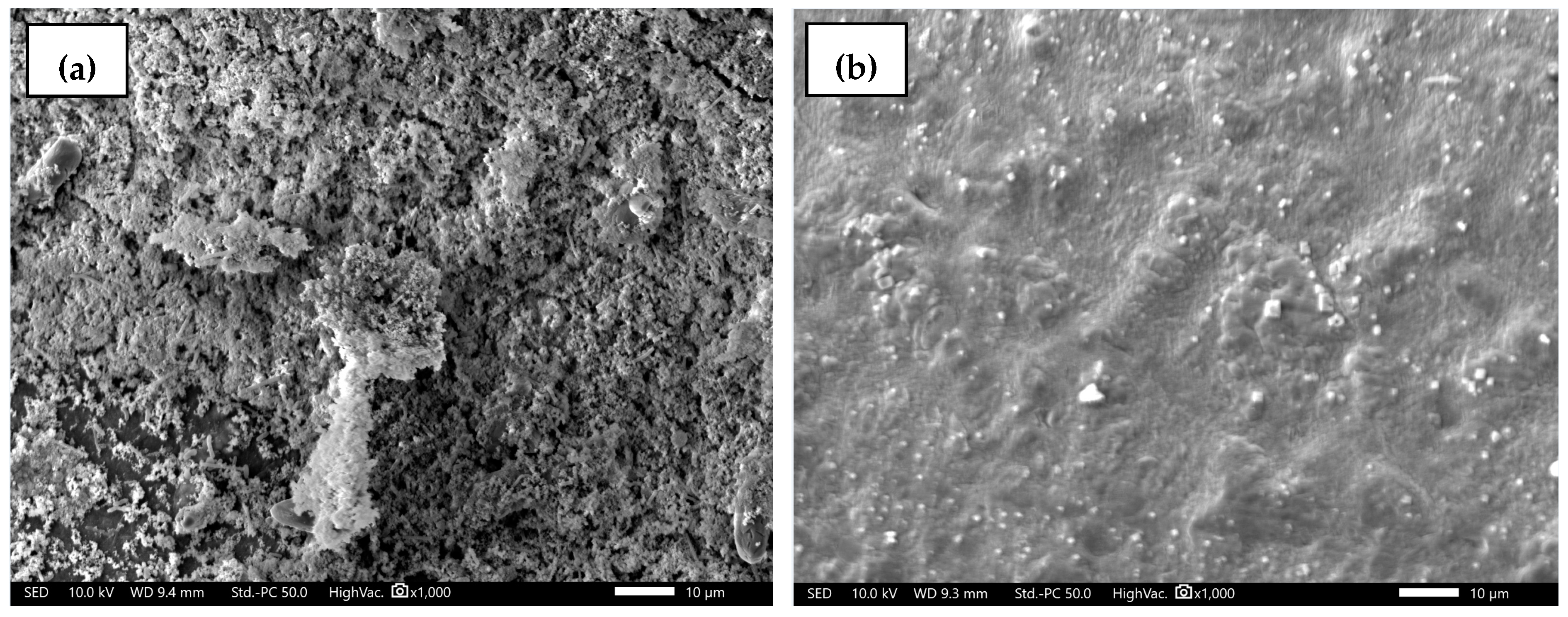
2.4.1. Membrane Morphology

The morphology of the obtained membranes was characterized with a high-resolution field emission scanning electron microscope (FESEM, JEOL JSM-IT700HR, USA). The membrane sample was first frozen and fractured in liquid nitrogen for cross-sectional observation of the hollow fiber membrane.

2.4.2. Contact Angle

The water contact angle (WCA) of the membrane was measured by a Contact Angle Measurement System equipped with SCA20 software (DataPhysics, USA) at room temperature. The membrane was cut open with a surgery knife. Then, 5 µL of DI water was dropped on the membrane surface, and the contact angle was measured in at least 5 different locations, and the average was recorded as the final result.

2.4.3. Porosity and Pore Size

The membrane porosity was determined by the kerosene immersion method [24]. The membranes were pre-dried in a vacuum chamber to remove residual water or solvent from the pores. Four pieces of each membrane, varying in length, were prepared, weighed, and immersed in high-purity kerosene. The membrane samples were immersed to ensure all the pores were filled with kerosene. On the fifth day, the membrane samples were weighed again, and porosity was determined using Equation (1) below. It was ensured that kerosene in the inner and outer surface of the wet membranes was removed and cleaned, respectively.
ε = 4 ( w o w f ) π l O D 2 I D 2 × 0.8
where ε is the membrane porosity; w o is the original weight of the membrane sample; w f is the final weight of the membrane after it is removed from the kerosene; l is the membrane sample’s length; and ID and OD are inside diameter and outside diameter, respectively.
The gas permeation test was used to measure the mean pore size of the hollow fiber membranes. The membrane modules were prepared with vacuum-dried membranes. The membrane’s lumen side was connected to a nitrogen gas-filled cylinder. The gas flow rate at different pressure was measured using a mass flow meter (Alicat Scientific, Phoenix, USA). Based on the relationship between pressure and the gas flow rate, the mean pore size of the membrane was calculated using Equation (2) below.
J = π n r 2 D k Δ p A m R T τ l
D k = 2 3 r 8 R T π M W
where J is the nitrogen gas flux (mol/m2s); n is the number of pores, r is the pore radius (m); Dk is the Knudsen diffusivity (m2/s); Δp is the gas pressure difference across the membrane; Am is the membrane area (m2); R is the gas constant (J/mol K); T is the temperature (K); τ is the tortuosity; l is the membrane thickness (m); and M W is the molecular weight of nitrogen gas.

2.5. Experimental Setup for Organics Separation (OS)

Figure 1 shows the schematic process flow chart of the UF experiment for organics separation from produced water. The membrane modules were assembled using an epoxy potting method. Briefly, three hollow fibers were placed into a stainless-steel tube, and both ends were sealed with epoxy such that the effective length of the hollow fibers was 20 cm. Each module was submerged in DI water for at least 48 h to ensure the fibers were fully wetted.
The experimental setup consists of a feed tank, a feed pump (D-series Teledyne ISCO pump), a permeate tank, a retentate/concentrate tank, a back pressure regulator, and the membrane module, as shown in Figure 1. Prior to the main filtration test, each module was pre-pressurized with DI water at 350 kPa to ensure that membrane pores were clean. The filtration experiment was performed in a cross-flow configuration by injecting decanoic acid (150 mg/L) and produced water through the membrane’s lumen at a predetermined pressure (50–350 kPa) and flow rate (0.018 to 0.059 m/s). The ultrafiltration experiments were carried out under different pressure, pH, and total dissolved solids. The pH of the feed solution made of sodium chloride (NaCl) was adjusted by hydrochloric acid (0.1 M HCl) and sodium hydroxide (0.1 M NaOH). During the ultrafiltration experiment, the trans-membrane pressure was controlled and maintained with the back pressure regulator. The permeate water was collected and weighed with an electronic balance. Both feed and permeate concentrations were measured with a Shimadzu TOC analyzer. The permeate water flux and rejection efficiency were calculated from Equations (4) and (5), respectively [25].
J p = m A × t
R   ( % ) = C f C p C f × 100
where J p is the water flux (kg/m2/h); m is the mass of permeate (kg); A is the cross-sectional area of the membrane (m2); and t is the total filtration time (hour). R is solute rejection (%); C f and C p are solute concentrations (mg/L) in feed and permeate, respectively.

2.6. Long-Term OS Experiments

Long-term membrane stability is a critical parameter for justifying the membrane’s potential for long-term and large-scale application. The flux recovery ratio (FRR) is used to determine the membrane’s long-term stability. To determine the FRR, continuous cyclic UF experiments were performed using real produced water as the feed solution. The non-purgeable organic carbon concentration is 10.2 mg/L. The total dissolved solid (TDS) of the produced water is 162,157.69 mg/L. Prior to the UF test, the pure water flux of the fresh membrane was measured. The operating pressure and flow rate are 100 kPa and 3 mL/min (0.018 m/s), respectively. After continuously injecting produced water for eight hours, the membrane was forward flushed with DI water. The pure water flux was measured after each DI water flushing. The membrane’s regeneration ability was determined by calculating the FRR after each cycle, using Equation (6) below.
F R R = J 2 J 1 × 100
where J 1 is the permeate water flux of the fresh membrane, and J 2 is the permeate water flux of the used membrane after regeneration with DI water.

3. Results and Discussion

3.1. Membrane Characterization

Table 2 illustrates the properties of the fabricated PVDF HF membrane. The molecular weight cut-off (MWCO) and mean pore size are 600 kPa and 62.7 nm, respectively, and the membrane’s porosity is 76%.
The membrane’s morphology is shown in Figure 2. It exhibits a highly porous, macrovoids-free structure along the cross-section that can be attributed to the synergistic effects of the additives PVP and LiCl, where PVP increases the membrane’s porosity, while LiCl reduces the membrane’s average pore size by strongly reacting with NMP to increase the dope viscosity and suppress the formation of large pores [19,26]. Figure 2d–h illustrate the morphologies of both inner and outer surfaces and edges of the membrane. Both sides show a thin skin surface, with a pore size around 60 nm, which is consistent with the pore size in Table 2 from the gas permeation measurement. Figure 2i shows that the water contact angle on the outer surface is 63.1°, indicating a hydrophilic membrane surface. Compared to the highly porous inner edge, the outer edge is dense with a thickness of 2 µm.

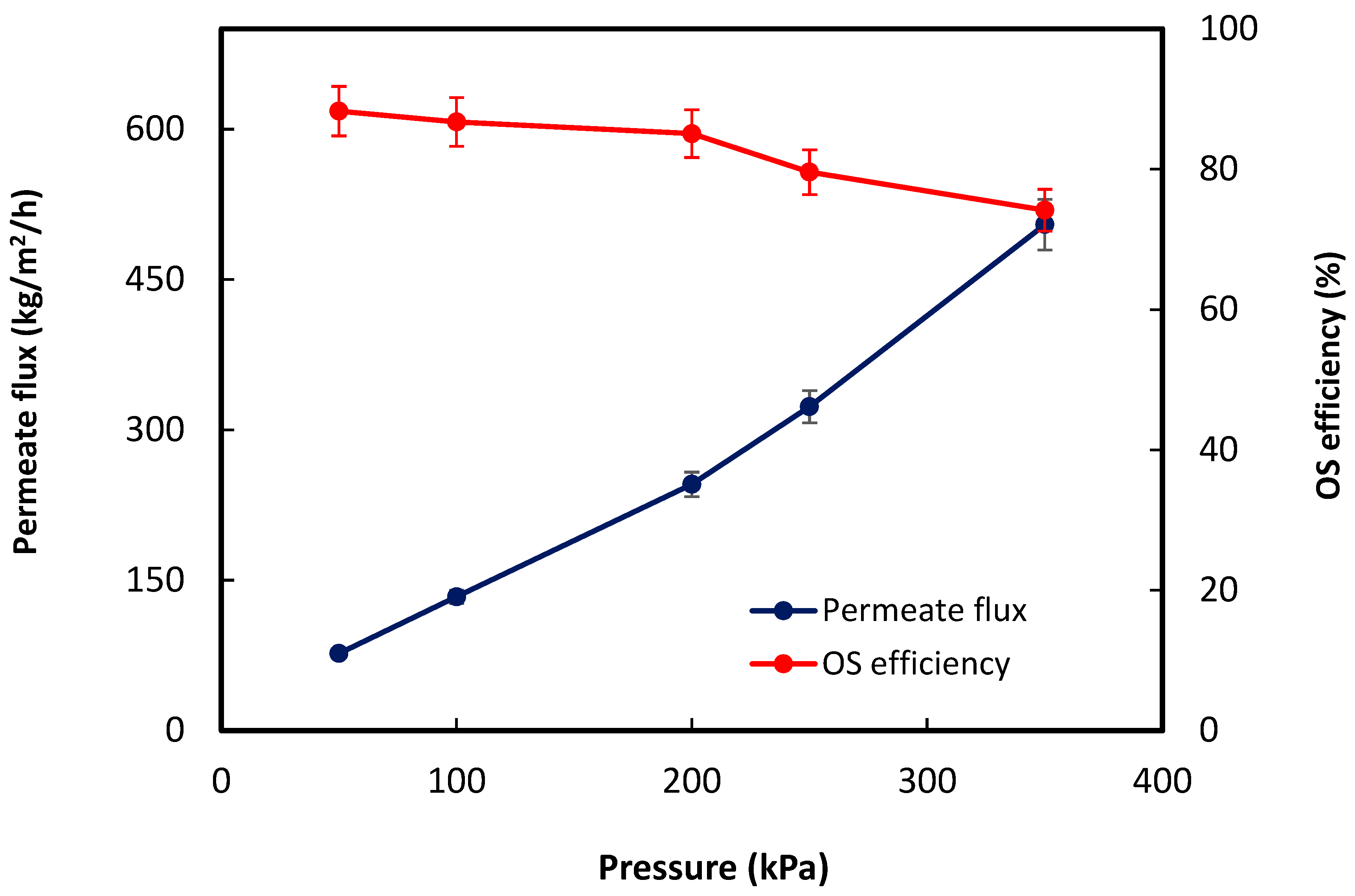
3.2. OS Performance Evaluation

The effect of operating pressure on the OS efficiency was first studied using 150 mg/L decanoic acid as the feed solution. Figure 3 shows the permeate water flux and organic separation (OS) efficiency at a flow rate of 10 mL/min (0.059 m/s) under different pressures. It is obvious that the permeate flux increased with the operating pressure. The membrane exhibited a permeate water flux of 504.88 kg/(m2h) at the pressure of 350 kPa, and the organics rejection was 74.16%. This could be attributed to the membrane’s uniform pore structure, which contains a highly porous, thick supporting layer between the two thin skin surfaces, as indicated by the SEM images in Figure 2. The rejection of decanoic acid decreased as the pressure increased due to the phenomenon of pore enlargement [26]. For example, when the driving force was 50 kPa, very few organics passed through the membrane. As the pressure increased, more organics flowed through the membrane due to an enlarged pore size and thus resulted in a declined organic rejection.
The decanoic acid solutions with different concentrations were prepared using a Qsonica sonicator (Newtown, CT, USA). The OS experiments were performed at 200 kPa and 10 mL/min (0.059 m/s). Figure 4 shows the permeate water flux and organic rejection at different feed concentrations. As the decanoic acid concentration increased from 25.31 to 102.41 mg/L, the rejection of decanoic acid increased. This result is similar to the report from Gryta et al. and Chakrabarty et al. that the size exclusion mechanism mainly controls the organics separation of the UF membranes [27,28]. During the OS process, the organics were blocked by the membrane because the pores were relatively smaller compared to the organics. As the decanoic acid concentration increased, the amount of organics being blocked at the membrane surface increased. The accumulated organics on the membrane surface might reduce the pore size. As a result, the amount of organics that passed through the membrane pores reduced, which led to a higher salt rejection. Other factors, such as negative surface charge of the membrane, can induce the interactions between organics and the membrane, which could also affect the separation efficiency of the membrane.
The reduced permeate water flux in Figure 4 could also be caused by pore blockage due to the high contents of organics in the feed solution. The increased organics concentration raised the osmotic pressure on the feed side, causing an increased viscosity in the boundary layer. As a result, the mass transfer coefficient of the water decreased, and thus the permeate water flux declined, as shown in Equation (7), as follows:
J = P π μ R t = P π μ R m + R f
J is the permeate flux, P is the transmembrane pressure (bar), π is the osmotic pressure (bar), μ is the viscosity of the solution (bar.h), R t is the total resistance (m−1), R m is the membrane resistance (m−1), and R f is the fouling resistance (m−1).
The pH of produced water ranges between 3.9 and 8.1. The effect of pH on membrane’s OS separation efficiency was studied in the pH range between 4.5 and 10. Hydrochloric acid (HCl) and sodium hydroxide (NaOH) were used to adjust the pH of the decanoic acid solution. Figure 5 shows that the permeate water flux slightly increased from 67.9 to 71.6 kg/m2/h when the pH increased from 4.5 to 6, and the flux was stable as the pH further increased to 10. The rejection of decanoic decreased from 70.6% to 49.8% when the pH increased from 4.5 to 10.
The OS performance at different pH can be explained by the structure of organic molecules in the feed solution. Decanoic acid in aqueous solution exhibits various forms, such as micelles, vesicles, or oil drops [29]. Micelles are aggregates with the hydrophilic carboxyl group facing outward and no water encapsulated in the center, while vesicles encapsulate water. The size of micelles is much smaller than that of vesicles. The structure of decanoic acid is highly determined by the solution pH, owning to the different ionization states of the hydrophilic carboxyl group. At high pH, the carboxyl groups were highly deprotonated, leading to the formation of carboxylate ions that repulsed each other. The structure of micelles can minimize the repulsion by maximizing the distance between the carboxylate ions while maintaining favorable Van der Waals interactions. In contrast, at low pH, there was no or limited carboxyl groups between the carboxyl groups, and the structure of the vesicle was formed. The change in the decanoic acid structure from vesicles at low pH to micelles at high pH resulted in the decline of organics rejection, as shown in Figure 5.
The flux and rejection efficiency with respect to the feed salinity are presented in Figure 6. The result indicated that as salinity increased from 10.6 g/L to 171.6 g/L, the permeate water flux decreased from 90.5 kg/m2/h to 69.81 kg/m2/h, which can be explained by the DLVO theory [30,31]. In produced water, organic matter usually carries a negative charge due to the presence of carboxylate and phenolate groups, such as fatty acids. The organic matter is dispersed in produced water by the electrostatic repulsion between the negatively charged groups. When sodium chloride is added, the dissociated sodium and chloride ions are distributed around the dispersed organics. Specifically, the positively charged sodium ions can shield the negatively charged groups of the organic matter, thereby reducing the intermolecular repulsion between the organic matters in produced water. Thus, the added salt created an electrostatic force of attraction (thus reduced repulsion) between the organic molecules. This attraction caused the organic molecules to aggregate and form the vesicle structure. The aggregation and deposition also created a layer (made of organic molecules and salt) at the membrane surface, which enhanced the osmotic pressure across the membrane. This phenomenon reduced the volume of water that passed through the membrane and yielded low permeate flux. Additionally, an increase in rejection efficiency was observed in Figure 5 as the salt concentration increased. As the organic molecules aggregated due to the presence of salt, the formation of a vesicle structure of the decanoic acid resulted in an increased OS efficiency.

3.3. Cyclic UF Experiments Using Real Oilfield-Produced Water as the Feed Solution

Real oilfield-produced water was used to evaluate the long-term OS performance of the membrane. The produced water was pre-filtered with a 50 µm filter and used as the feed solution. Figure 7 and Figure 8 show permeate water flux and OS efficiency in the continuous cyclic experiments. The operating pressure and flow rate were 100 kPa and 3 mL/min (0.018 m/s), respectively. The membrane was forward-flushed for regeneration between every two consecutives cycles. It is shown in Figure 7 that the permeate water flux was stable at 11.56 kg/(m2·h) during the first experimental cycle. The flux slightly decreased in the following five experimental cycles. The flux was recovered and even slightly increased after each single experimental cycle. This can be explained by the increased pore wetting after the forward-flush regeneration under a relatively low operating pressure (100 kPa). Compared to the stable flux, the organics rejection declined with operating time in every cyclic UF experiment, which can be explained by the presence of various organic compounds, such as polycyclic aromatic hydrocarbons (PAH), total petroleum hydrocarbons (TPH), and the oil and grease with a wide range of molecular weights. The organic components with a molecular weight smaller than the membrane’s molecular weight cut-off (MWCO) result in a gradually decreased organics rejection. After every membrane regeneration, the organics rejection was almost 100% recovered, indicating a robust anti-fouling property of the hydrophilic PVDF membrane. It is worth noting that the initial OS efficiency remained at around 68.2% even though the flux increased because the pore structure, specifically pore size, was stable during the UF and membrane regeneration process under low pressure.
Figure 9 shows the morphologies of the used membrane after the long-term OS experiments. During the UF experiment, real produced water flows along the lumen side, and a loose cake layer forms on the inner surface. Compared to the clean and smooth outer surface of the fresh membranes, as shown in Figure 2, significant amounts of dispersed spherical particles were found on the outer surfaces of the used membrane, as observed in Figure 9b. The EDS spectra at different positions on the inner surface of the used membrane are shown in Figure S1. The results indicated that the major compositions of the filter cake are iron (Fe), oxygen (O), calcium (Ca), and silica (Si). This can be explained by the complex composition of produced water in the Permian Basin. The produced water contains more than 160,000 mg/L total dissolved solids (TDS), and the iron concentration has been reported to be greater than 100 mg/L [32]. The presence of a significant amount of iron decreased the silica’s solubility, resulting in silica precipitation from the produced water [33].
Figure S2 shows the linear EDX spectra along the cross-section of the membrane before and after the OS experiments. The fresh membrane is made of carbon (C), fluoride (F), and oxygen (O) from the PVDF polymer resin. However, the used membrane shows several new elements, including chloride (Cl), potassium (K), calcium (Ca), and iron (Fe). Comparing the chemical composition between the inner surface and cross-section in Figure S2a,b, respectively, silica is only found on the inner surface, while sodium chloride is present in the membrane’s matrix.
Figure 10 shows the FTIR spectra of the fresh hydrophilic PVDF HF membrane, the used membrane after the cyclic experiments, and the regenerated membrane. The characteristic peak of PVDF at 1725 cm−1 can be considered as a reference for the comparison. Compared to the fresh membrane, the intensity of the peak at 1650 cm−1 attributed to the C=O stretching from carbonate is much higher for the used membrane; additionally, small new peaks appeared at 1540 cm−1, which can also be attributed to the C=O stretching from carbonate scaling. It is worth noting that no obvious organics-reduced fouling phenomenon can be found from the FTIR spectra, due to the consistent hydrophilic nature of the membranes, as shown in Figure 11. The water contact angles of the membranes were between 60° and 70° during the 60 h cyclic experiments. For the regenerated membrane, the intensity of the peak at 1650 cm−1 in Figure 10 is reduced, and the small peak at 1540 cm−1 disappeared, indicating the highly effective regenerative capacity of the hydrophilic PVDF membranes.

4. Conclusions

Hydrophilic PVDF hollow fiber membranes were formulated and prepared for the removal of organic matters from produced water. The hydrophilic membrane shows double-skinned microvoids-free morphologies. The OS results show that the operating parameters significantly affected the OS efficiencies. Especially, the increase in feed concentration improved the OS efficiency but reduced the permeate flux. The pH change showed a negligible effect on the permeate flux, but the pH increase can result in a remarkable decline of OS efficiency. Long-term cyclic experiments were performed, and the results indicated a slight water flux decline due to carbonate scaling. Nonetheless, after six OS cycles (8 h per cycle), a near-100% recovery of organics separation efficiency was achieved using actual produced water as the feed solution. The developed hydrophilic PVDF HF membrane-based ultrafiltration process provided a portable and durable strategy for organic separation from high-salinity produced water.

Supplementary Materials

The following Supporting Information can be downloaded at: https://www.mdpi.com/article/10.3390/fib13030031/s1, Figure S1: EDX images acquired from different positions on the inner surface of the used hydrophilic PVDF HF membranes. Figure S2: EDX spectra of the cross-section of the hydrophilic PVDF HF membranes before and after OS experiments.

Author Contributions

Conceptualization, S.O. and J.Y.; methodology, S.O.; software, G.Z.; validation, G.Z. and J.Y.; formal analysis, S.O., Z.H. and G.T.F.; investigation, S.O. and Z.H.; resources, J.Y.; data curation, S.O. and Z.H.; writing—original draft preparation, S.O.; writing—review and editing, J.Y.; visualization, Z.H. and G.Z.; supervision, J.Y.; project administration, G.Z. and J.Y.; funding acquisition, J.Y. All authors have read and agreed to the published version of the manuscript.

Funding

The authors would like to acknowledge the financial support from the Bureau of Reclamation (BOR) through the Desalination and Water Purification Research Program (R21AC10268), and the New Mexico Petroleum Recovery Research Center (PRRC). The author also thanks Arkema Inc. for providing PVDF material.

Data Availability Statement

The data presented in this study are available on request from the corresponding author.

Conflicts of Interest

The authors declare no conflict of interest.

References

  1. Dardor, D.; Al-Maas, M.; Minier-Matar, J.; Janson, A.; Sharma, R.; Hassan, M.K.; Al-Maadeed, M.A.A.; Adham, S. Protocol for Preparing Synthetic Solutions Mimicking Produced Water from Oil and Gas Operations. ACS Omega 2021, 6, 6881–6892. [Google Scholar] [CrossRef]
  2. Rahman, W.U.; Khan, M.D.; Khan, M.Z.; Halder, G. Anaerobic biodegradation of benzene-laden wastewater under mesophilic environment and simultaneous recovery of methane-rich biogas. J. Environ. Chem. Eng. 2018, 6, 2957–2964. [Google Scholar] [CrossRef]
  3. Shokrollahzadeh, S.; Golmohammad, F.; Naseri, N.; Shokouhi, H.; Arman-mehr, M. Chemical Oxidation for Removal of Hydrocarbons from Gas–Field Produced Water. Procedia Eng. 2012, 42, 942–947. [Google Scholar] [CrossRef]
  4. Sinha, S.; Roy, D.; Roy, O.; Neogi, S.; De, S. Removal of organic contaminants from flowback water using Fenton process. J. Water Process Eng. 2022, 47, 102680. [Google Scholar] [CrossRef]
  5. Zhang, Y.; Zhao, E.; Cui, X.; Zhu, W.; Han, X.; Yu, G.; Wang, Y. Removal of organic compounds from shale gas fracturing flowback water by an integrated electrocoagulation and electro-peroxone process. Sep. Purif. Technol. 2021, 265, 118496. [Google Scholar] [CrossRef]
  6. Jaynes, W.F.; Vance, G.F. BTEX Sorption by Organo-Clays: Cosorptive Enhancement and Equivalence of Interlayer Complexes. Soil Sci. Soc. Am. J. 1996, 60, 1742–1749. [Google Scholar] [CrossRef]
  7. Nicholas, E.R.; Cath, T.Y. Evaluation of sequencing batch bioreactor followed by media filtration for organic carbon and nitrogen removal in produced water. J. Water Process Eng. 2021, 40, 101863. [Google Scholar] [CrossRef]
  8. Freire, D.D.; Cammarota, M.C.; Santanna, G.L., Jr. Biological treatment of oil field wastewater in a sequencing batch reactor. Environ. Technol. 2001, 22, 1125–1135. [Google Scholar] [CrossRef]
  9. Mousa, I.E. Total petroleum hydrocarbon degradation by hybrid electrobiochemical reactor in oilfield produced water. Mar. Pollut. Bull. 2016, 109, 356–360. [Google Scholar] [CrossRef]
  10. Ebrahimi, M.; Willershausen, D.; Ashaghi, K.S.; Engel, L.; Placido, L.; Mund, P.; Bolduan, P.; Czermak, P. Investigations on the use of different ceramic membranes for efficient oil-field produced water treatment. Desalination 2010, 250, 991–996. [Google Scholar] [CrossRef]
  11. Fakhru’l-Razi, A.; Pendashteh, A.; Abdullah, L.C.; Biak, D.R.A.; Madaeni, S.S.; Abidin, Z.Z. Review of technologies for oil and gas produced water treatment. J. Hazard. Mater. 2009, 170, 530–551. [Google Scholar] [CrossRef]
  12. Samuel, O.; Othman, M.H.D.; Kamaludin, R.; Sinsamphanh, O.; Abdullah, H.; Puteh, M.H.; Kurniawan, T.A.; Li, T.; Ismail, A.F.; Rahman, M.A.; et al. Oilfield-produced water treatment using conventional and membrane-based technologies for beneficial reuse: A critical review. J. Environ. Manag. 2022, 308, 114556. [Google Scholar] [CrossRef]
  13. Badrnezhad, R.; Beni, A.H. Ultrafiltration membrane process for produced water treatment: Experimental and modeling. J. Water Reuse Desalination 2013, 3, 249–259. [Google Scholar] [CrossRef]
  14. Liu, N.; Li, L.; McPherson, B.; Lee, R. Removal of organics from produced water by reverse osmosis using MFI-type zeolite membranes. J. Membr. Sci. 2008, 325, 357–361. [Google Scholar] [CrossRef]
  15. Wandera, D.; Wickramasinghe, S.R.; Husson, S.M. Modification and characterization of ultrafiltration membranes for treatment of produced water. J. Membr. Sci. 2011, 373, 178–188. [Google Scholar] [CrossRef]
  16. Zha, S.; Zhang, G.; Dawson, N.; Yu, J.; Liu, N.; Lee, R. Study of PVDF/Si-R hybrid hollow fiber membranes for removal of dissolved organics from produced water by membrane adsorption. Sep. Purif. Technol. 2016, 163, 290–299. [Google Scholar] [CrossRef]
  17. Rajabzadeh, S.; Liang, C.; Ohmukai, Y.; Maruyama, T.; Matsuyama, H. Effect of additives on the morphology and properties of poly(vinylidene fluoride) blend hollow fiber membrane prepared by the thermally induced phase separation method. J. Membr. Sci. 2012, 423–424, 189–194. [Google Scholar] [CrossRef]
  18. Abed, M.R.M.; Kumbharkar, S.C.; Groth, A.M.; Li, K. Ultrafiltration PVDF hollow fibre membranes with interconnected bicontinuous structures produced via a single-step phase inversion technique. J. Membr. Sci. 2012, 407–408, 145–154. [Google Scholar] [CrossRef]
  19. Shi, L.; Wang, R.; Cao, Y.; Liang, D.T.; Tay, J.H. Effect of additives on the fabrication of poly(vinylidene fluoride-co-hexafluropropylene) (PVDF-HFP) asymmetric microporous hollow fiber membranes. J. Membr. Sci. 2008, 315, 195–204. [Google Scholar] [CrossRef]
  20. Wang, D.; Li, K.; Teo, W.K. Porous PVDF asymmetric hollow fiber membranes prepared with the use of small molecular additives. J. Membr. Sci. 2000, 178, 13–23. [Google Scholar] [CrossRef]
  21. Khayet, M.; Feng, C.Y.; Khulbe, K.C.; Matsuura, T. Preparation and characterization of polyvinylidene fluoride hollow fiber membranes for ultrafiltration. Polymer 2002, 43, 3879–3890. [Google Scholar] [CrossRef]
  22. Han, M.-J.; Nam, S.-T. Thermodynamic and rheological variation in polysulfone solution by PVP and its effect in the preparation of phase inversion membrane. J. Membr. Sci. 2002, 202, 55–61. [Google Scholar] [CrossRef]
  23. Fontananova, E.; Jansen, J.C.; Cristiano, A.; Curcio, E.; Drioli, E. Effect of additives in the casting solution on the formation of PVDF membranes. Desalination 2006, 192, 190–197. [Google Scholar] [CrossRef]
  24. Zou, L.; Zhang, X.; Gusnawan, P.; Zhang, G.; Yu, J. Crosslinked PVDF based hydrophilic-hydrophobic dual-layer hollow fiber membranes for direct contact membrane distillation desalination: From the seawater to oilfield produced water. J. Membr. Sci. 2021, 619, 118802. [Google Scholar] [CrossRef]
  25. Zha, S.; Gusnawan, P.; Zhang, G.; Liu, N.; Lee, R.; Yu, J. Experimental study of PES/SiO2 based TFC hollow fiber membrane modules for oilfield produced water desalination with low-pressure nanofiltration process. J. Ind. Eng. Chem. 2016, 44, 118–125. [Google Scholar] [CrossRef]
  26. Zha, S.; Yu, J.; Zhang, G.; Liu, N.; Lee, R. Polyethersulfone (PES)/cellulose acetate butyrate (CAB) composite hollow fiber membranes for BTEX separation from produced water. RSC Adv. 2015, 5, 105692–105698. [Google Scholar] [CrossRef]
  27. Gryta, M.; Karakulski, K.; Morawski, A.W. Purification of oily wastewater by hybrid UF/MD. Water Res. 2001, 35, 3665–3669. [Google Scholar] [CrossRef]
  28. Chakrabarty, B.; Ghoshal, A.K.; Purkait, M.K. Ultrafiltration of stable oil-in-water emulsion by polysulfone membrane. J. Membr. Sci. 2008, 325, 427–437. [Google Scholar] [CrossRef]
  29. Monnard, P.A.; Deamer, D.W. Membrane self-assembly processes: Steps toward the first cellular life. Anat. Rec. 2002, 268, 196–207. [Google Scholar] [CrossRef]
  30. Elzo, D.; Huisman, I.; Middelink, E.; Gekas, V. Charge effects on inorganic membrane performance in a cross-flow microfiltration process. Colloids Surf. A Physicochem. Eng. Asp. 1998, 138, 145–159. [Google Scholar] [CrossRef]
  31. Yi, X.S.; Yu, S.L.; Shi, W.X.; Sun, N.; Jin, L.M.; Wang, S.; Zhang, B.; Ma, C.; Sun, L.P. The influence of important factors on ultrafiltration of oil/water emulsion using PVDF membrane modified by nano-sized TiO2/Al2O3. Desalination 2011, 281, 179–184. [Google Scholar] [CrossRef]
  32. Shields, A.; Sharma, R.; McLin, K.; Bjornen, K.; Jenneman, G.; Freeman, J.; Mesa, W. Three Years of Water Treatment in the Permian: A ConocoPhillips Case History. In Proceedings of the SPE/AAPG/SEG Unconventional Resources Technology Conference, San Antonio, TX, USA, 20–22 July 2015. [Google Scholar]
  33. Cob, S.S.; Hofs, B.; Maffezzoni, C.; Adamus, J.; Siegers, W.G.; Cornelissen, E.R.; Güner, F.E.G.; Witkamp, G.J. Silica removal to prevent silica scaling in reverse osmosis membranes. Desalination 2014, 344, 137–143. [Google Scholar]
Figure 1. Schematic diagram of the UF experiment for organic matter removal from produced water.
Fibers 13 00031 g001
Figure 2. SEM images of the PVDF hollow fiber membrane (ac) cross-sectional overview; (d) inner surface; (e) inner edge; (f) outer edge; (g,h) outer surface; (i) water contact angle on the outer surface.
Fibers 13 00031 g002
Figure 3. Effect of operating pressure on permeate water flux and organics separation efficiencies; 150 mg/L decanoic acid was used as the feed solution.
Fibers 13 00031 g003
Figure 4. Effect of total organic carbon (TOC) on permeate water flux and organics separation efficiencies.
Fibers 13 00031 g004
Figure 5. Effect of pH on permeate water flux and organics rejection of the PVDF HF membrane.
Fibers 13 00031 g005
Figure 6. Rejection efficiency and permeate flux of the hydrophilic PVDF membrane at different NaCl concentrations.
Fibers 13 00031 g006
Figure 7. Cyclic permeate water flux of the membrane using real produced water as the feed solution.
Fibers 13 00031 g007
Figure 8. Organics rejection of the membrane in cyclic UF experiments for organics separation.
Fibers 13 00031 g008
Figure 9. SEM images of the used hydrophilic PVDF HF membranes: (a) inner surface, scale bar: 10 µm; (b) outer surface, scale bar: 10 µm.
Fibers 13 00031 g009
Figure 10. FTIR spectra of the fresh hydrophilic PVDF HF membrane, and the membrane before and after regeneration between each cyclic UF experiment.
Fibers 13 00031 g010
Figure 11. Contact angles of the hydrophilic PVDF HF membrane before and after 60 h of cyclic UF experiments.
Fibers 13 00031 g011
Table 1. Spinning parameters for hollow fiber membrane fabrication.
ParametersValue
Dope Composition (wt.%)PVDF/PVP/LiCl/NMP (18/9/3/70)
Bore fluid (wt.%)NMP/water (30/70)
External coagulantTap water
Dope flow rate (mL/min)2
Bore flow rate (mL/min)0.5
Length of the air gap (cm)7
Take-up speedfree fall
Table 2. Characteristics of the hollow fiber membranes.
PropertiesThickness (um)MWCO (kDa)Mean Pore Size (nm)Porosity (%)
Values21960062.776
Disclaimer/Publisher’s Note: The statements, opinions and data contained in all publications are solely those of the individual author(s) and contributor(s) and not of MDPI and/or the editor(s). MDPI and/or the editor(s) disclaim responsibility for any injury to people or property resulting from any ideas, methods, instructions or products referred to in the content.

