Article

Effect of GFRP and CFPR Hybrid Confinement on the Compressive Performance of Concrete

by
Marina L. Moretti
School of Architecture, National Technical University of Athens, 10682 Athens, Greece
Fibers 2025, 13(2), 12; https://doi.org/10.3390/fib13020012
Submission received: 29 October 2024 / Revised: 1 January 2025 / Accepted: 22 January 2025 / Published: 24 January 2025
(This article belongs to the Special Issue Fracture Behavior of Fiber-Reinforced Building Materials)

Abstract

:
Application of hybrid jackets consisting of comparatively stiff FRP materials for the seismic retrofit of substandard RC columns, aiming at reducing the risk of buckling and of brittle failure, which are typical to older columns, is a promising challenge. Given the sparsity of similar experimental data, the objective of this paper is to study the hybrid effect in concrete confined with conventional carbon- and glass- reinforced polymer fabrics (CFRP and GFRP, respectively). Twenty-six concrete cylinders, wrapped by one to three layers of CFRP and GFRP with different fiber configurations, were tested in compression. A clear hybrid effect was observed, consisting of a less brittle failure and an improved confinement as compared to the behavior of simple jackets. Furthermore, hybrid specimens, in which a CFRP layer is substituted by a GFRP layer, appear to display similar efficiency in confinement compared to specimens with a stiffer jacket consisting of more CFRP sheets, which are expected to experience 30 to 40% higher lateral pressure owing to the stiffer jacket. A design model to estimate peak concrete compressive strength and axial strain is proposed. The results are promising towards the potential application of similar hybrid jackets for the seismic rehabilitation of older RC columns.

1. Introduction

Fiber-reinforced polymer (FRP) composites are increasingly gaining popularity for strengthening and rehabilitation of concrete since the late 1990s, owing to their remarkable stiffness and strength-to-mass ratio. FRPs are particularly effective when applied to concrete structural elements subjected to compression, with the fibers oriented along the cross-section perimeter, perpendicular to the axial load. FRP jackets are activated when the compression load exceeds the axial strength of the unconfined element, after which the concrete section tends to expand radially because of internal cracking. FRP materials behave elastically up to failure and introduce confining stresses in the plane of the section resulting in a tri-axial stress-state and, hence, in enhanced mechanical properties, i.e., compressive strength and deformability of the retrofitted element. Experimental research initially focused on the compressive performance of columns with external jackets consisting usually of a single type of carbon FRP (CFRP) wraps with a variable number of layers, e.g., [1,2,3]. FRPs have been applied also for prefabricated tubes, which were subsequently filled by concrete [4,5,6,7]. Early on, numerous models have been proposed to estimate either only the peak strength and deformation characteristics of confined concrete, usually designated as ‘design’ models, e.g., [8,9,10,11], or ‘analytical’ models aimed at reproducing the whole stress-strain curve of confined concrete [12]. Review studies focusing on the comparative performance of different design models, e.g., [13,14], assess the predictive capacity of existing models, based on broad experimental databases.
The potential of mixing different types of fibers in an epoxy resin matrix in order to obtain a material with the combined advantages and reduced disadvantages of the individual components has been investigated since the 1970s [15]. Initial research focused on mixing glass and carbon fibers to reduce the cost and brittle failure of carbon fibers [16,17,18,19,20]. The procedure of incorporating two or more fibers within a single matrix was designated as ‘hybridisation’, and the resulting composite is referred to as ‘hybrid’. Tests on laminates made of glass and carbon fibers often result in an apparent increase of the strain at failure, as compared to the ultimate strain of the more brittle non-hybrid component/composite, and in a progressive—instead of imminent—type of failure. This behavior consists of the ‘hybrid effect’, as was first reported by Hayashi [20]. The hypotheses formulated regarding the causes of the hybrid effect are well summarized in the review paper of Swolf et al. [21]. Causes of the hybrid effect include (a) residual shrinkage stresses, attributed to the difference in the thermal contraction behavior of the different types of fibers, and (b) progressive failure of the individual fiber components, which have different strength and deformation characteristics and are subjected to the same axial and lateral deformation.
Lin and Chen [22] from testing concrete cylinders, with diameter 100 mm, and height 200 mm, and unconfined concrete strength 25 MPa, wrapped by different configurations of three layers of glass and carbon fibers, reached the conclusion that higher axial strength is achieved (5 to 22%) when the glass fibers are in contact with the concrete, with 22% strength increase corresponding to one layer of GFRP and two layers of GFRP, while 5% strength increase corresponds to two GFRP and one CFRP layer. Lin and Chen [22] attributed this behavior to that the brittle carbon fibers are comparatively more liable to fail than the glass fibers because of the crushed concrete. It is noted that the compressive strength values obtained from the tests are high, compared to other test results from the literature, possibly because of scale effect given the small dimensions of the cylinders. Wu et al. [23] studied the effect of one to three layers of FRP jackets on the axial behavior of concrete cylinders, with diameter 150 mm and height 300 mm, by applying through wet lay-up process five different fibers, with varying strength and deformation characteristics, i.e., two types of CFRP, aramid FRP, GFRP, and PBO FRP, and observed that a combination of a high-strength FRP sheet to a high-ductility (i.e., high deformability) FRP sheet results in an increase of the ultimate strength, while the ultimate strain of the hybrid specimen is similar to that of the counterpart specimen confined only with the high-ductility FRP sheet.
Lately, high-elongation (HE)—or large rupture strain (LRS)—fibers have been developed, with ultimate strain 5–10%, mixed with conventional low-elongation (LE), fibers [24], e.g., carbon and glass, aiming at hybrid FRPs with ‘pseudo ductile’ performance, i.e., in increased deformation after peak strength, owing to the occurrence of damage, which results in a less brittle failure [25,26,27,28]. Pseudo ductility may be achieved, among other mechanisms, through fiber re-orientation, layer sequence, hybridisation, and interfacial slip in discontinuous fiber composites [29]. Alternative efficient hybrid materials used for confinement, with reduced brittleness and low cost, include FRP ropes [30,31,32,33], as well as eco-friendly, recyclable materials [34,35,36].
Particularly efficient hybrid FRP configurations towards a pseudo ductile behavior apparently seem to be hybrid composites consisting of stiff fibers in contact with concrete, surrounded by a comparatively very flexible material that allows for deformation after the inner jacket ruptures. Indicatively, Bai et al. [37] and Ispir et al. [38] tested in compression hybrid jacketed concrete cylinders 150 mm/300 mm, using carbon FRP (CFRP) or glass FRP (GFRP) as the inner layer, and in the outer layer either LRS FRP polyethylene terephthalate (PET) or LRS FRP polyethylene naphthalate (PEN), with rupture strains, εfu, 5 to 10%, and elastic modulus, Ef, 10 to 25 GPa. In both cases, the inner layer, i.e., CFRP (Ef ≈ 230 GPa, εfu ≈ 1.5%) or GFRP (Ef ≈ 80 GPa, εfu ≈ 3%), which provided stiffness to the retrofitted column, failed first. After failure of the inner layer the outer LRS FRP layer, with considerably higher deformation capacity, proved sufficient to sustain the energy released after the rupture of the inner FRP layer, and it even carried more load before failure. Hence, similar hybrid confinement configurations achieve a progressive type of failure, i.e., pseudo ductility. Similar progressive failure of the different individual FRP components of the jacket was also observed in the tests of Wu et al. [23]. It is noted that the performance of similar hybrid FRP configurations resides in the substantially different strength and deformation characteristics of the individual FRP materials and differs from the original ‘hybrid effect’ first reported by Hayashi [20].
FRP jackets can improve considerably the seismic performance of substandard RC columns, e.g., [39,40,41,42]. Hybrid, instead of simple, FRP jackets could be a promising alternative towards ductility enhancement of older RC-frame columns. It has been established that comparatively stiffer FRP jackets are more effective in restraining the longitudinal bars from buckling in older columns with sparsely spaced stirrups [43], compared to LRS FRP jackets [44].
Incentive for this study was the very limited available experimental studies regarding the behavior of comparatively stiffer hybrid jackets on the compressive behavior of concrete. The present work studies the compressive performance of concrete wrapped by jackets consisting of CFRP and GFRP with typical fiber characteristics. Plain concrete cylinders with dimensions 305 mm height and 152 mm diameter that were wrapped with one to three glass and/or carbon layers, with different relative positions of the FRP layers, were subjected to axial compression. The results of this study are promising towards the application of similar hybrid jackets for retrofitting substandard RC columns.

2. Experimental Program

2.1. Test Specimens

A total of 26 plain concrete cylinders, with height H = 305 mm (12 in) and diameter D = 152 mm (6 in), reinforced by carbon- and glass- fiber-reinforced polymer sheets, CFRP and GFRP, respectively, were manufactured and subjected to axial compression. FRP jackets consist of one, two, and three individual FRP layers, each with overlap length equal to 100 mm. Specimens with a single type of fibers, i.e., only CFRP or only GFRP, with one, two, and three layers, designated in the following as ‘simple’ or ‘conventional’ jackets, as well as specimens with jackets consisting of both types of fibers, henceforth designated as ‘hybrid’ specimens, were tested. Three identical specimens were prepared for each fabric configuration.
Specimens’ names depict the configuration of the FRP layers used for the jacket, as follows: Each layer is represented by the letters C, or G, for carbon and glass fabric layers, respectively. The first letter designates the FRP layer in contact with the concrete surface, and the next letters correspond to the sequence of the other layers. The Arabic numeral, 1 to 3, following the letters, indicates the number of the specific specimen, among three identical specimens. For example, GCC-1 is specimen -1, with a jacket consisting of one glass layer in contact with concrete, and two more carbon layers.
For the fabrication of FRP jackets unidirectional woven fiber fabrics were used and dry application process was applied. The direction of the fibers was parallel to the plane of the cylinder diameter. Prior to the application of the jackets, the concrete surface was cleaned from loose concrete particles that might reduce bond at the interface between concrete and the jacket (Figure 1a), then cleaned with water and left to dry. A two-part epoxy impregnation resin was applied. Epoxy components were meticulously weighed to obtain the correct proportions, and they were mixed for 4 min with a mixing spindle attached to a slow-speed electric drill according to the manufacturer’s guidelines. A clean container was used each time for mixing. The epoxy was then applied on the cylinder by means of a roller. Consecutively, the fabric was wrapped manually as tightly as possible around the epoxy-covered cylinder, and then the fabric was impregnated with epoxy (Figure 1b). It is noted that no specific measures were taked to ensure that the tightening of the FRP jacket was identical for all three samples of each jacket configuration, which may be one of the reasons for the slight variations observed in the compressive behaviour of each type of specimens.
When multiple layers were applied, the same procedure was followed. The overlapping length of each layer amounted to 100 mm. If two layers were applied, the overlap of the second layer was placed at 180 deg. From the first layer. In case of three layers, the overlap regions of the fabrics were placed at angles of 120 deg.
The jackets in the initially manufactured specimens ended at 40 mm from the specimen’s edges so as to avoid axial loading of the jacket during testing. Unfortunately, this resulted in premature failure at the ends of the specimens, before full activation of the jacket was achieved. Those specimens are not presented in the following. The remaining specimens were reinforced by CFRP strips of 40-mm width at both ends prior to testing, which prevented the end parts from failing prematurely. It is noted that numbering of the specimens included in this paper follows the initial numbering.

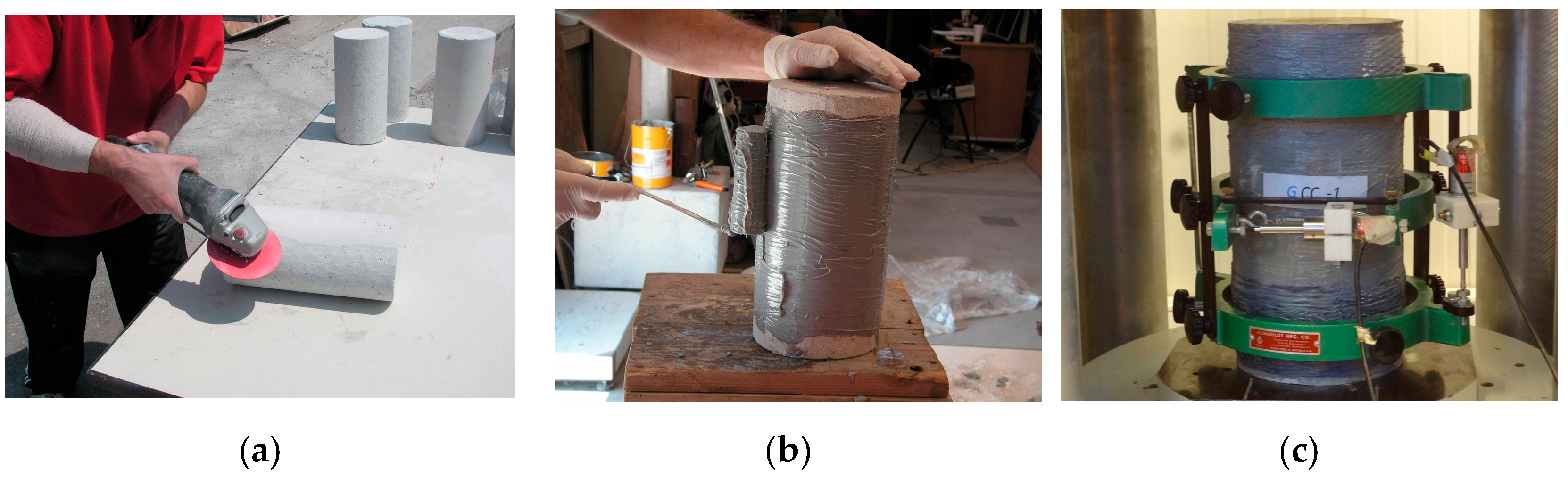
2.2. Test Set-Up and Instrumentation

The cylinder specimens were subjected to axial monotonic compression by means of a 3000-kN capacity universal/DMG hydraulic testing machine. Before testing, capping of both ends of the cylinders was performed, using material of high compressive strength, to ensure parallel surfaces and uniform distribution of axial pressure. The compression test speed was in general 40 μm/s.
The axial and lateral strains of concrete were recorded by two linear variable displacement transducers (LVDT), adapted to a special testing arrangement at mid-height of the cylinder (Figure 1c).

2.3. Material Properties

Ready mix concrete was used. All specimens were cast simultaneously. The concrete compressive strength, fco, was 24.5 MPa, and the corresponding axial strain, εco, was 0.0018, determined from three 152/305-mm cylinder samples at the time the test program was performed.
Unidirectional woven fiber fabrics, namely carbon SikaWrap-230 C and glass SikaWrap-430G, were used. The properties of the FRP materials as provided by the manufacturer are shown on Table 1. It is noted that the ultimate strains at failure, εfu, are calculated as the ratio of the tensile strength to the modulus of elasticity.
A two-part epoxy impregnation resin was applied, Sikadur-330, with tensile strength equal to 30 MPa, tensile modulus of elasticity E = 4.5 GPa, and ultimate strain at failure εu = 0.9%. Dry lay-up process was performed.

3. Experimental Results—Discussion
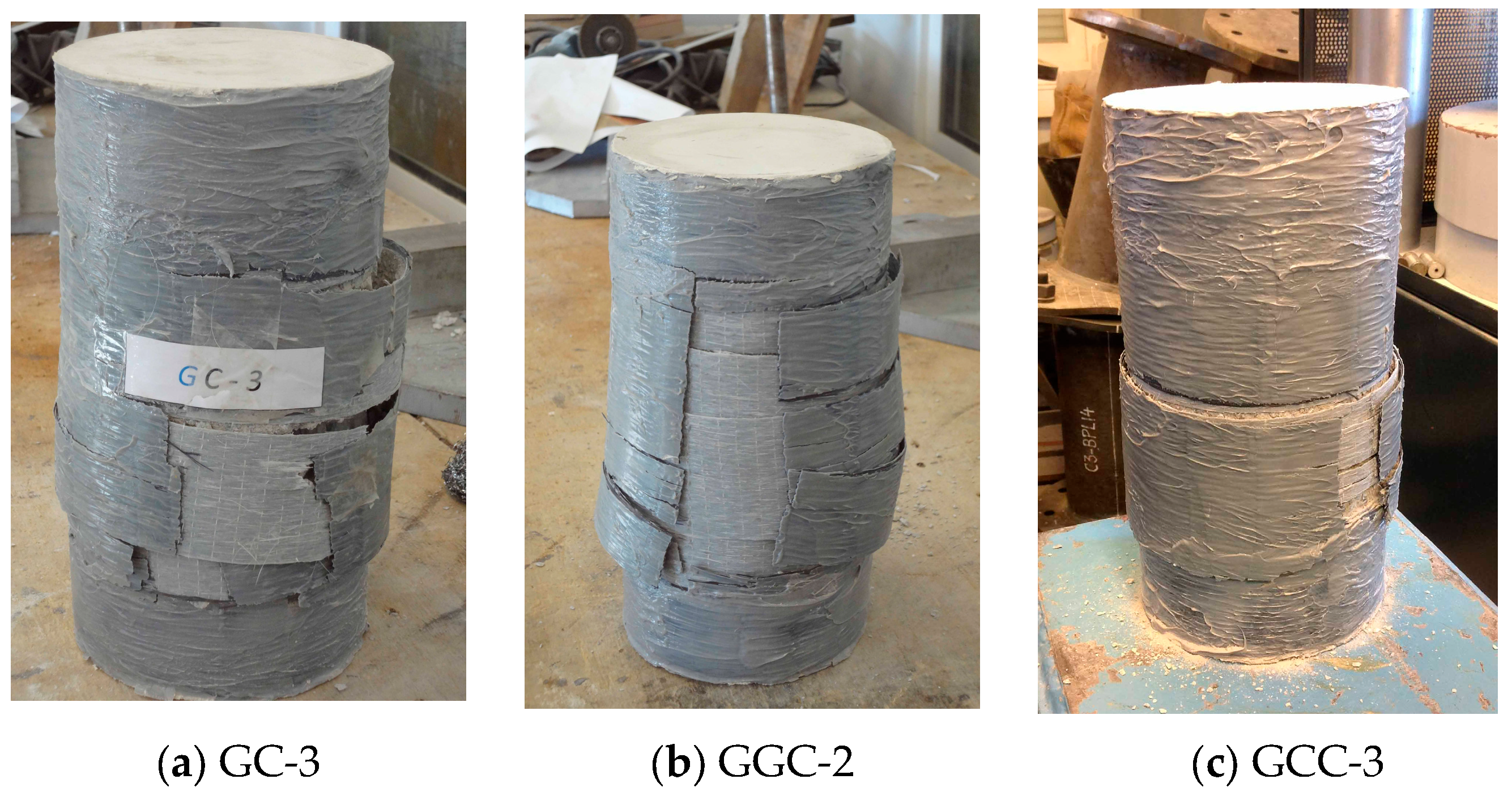
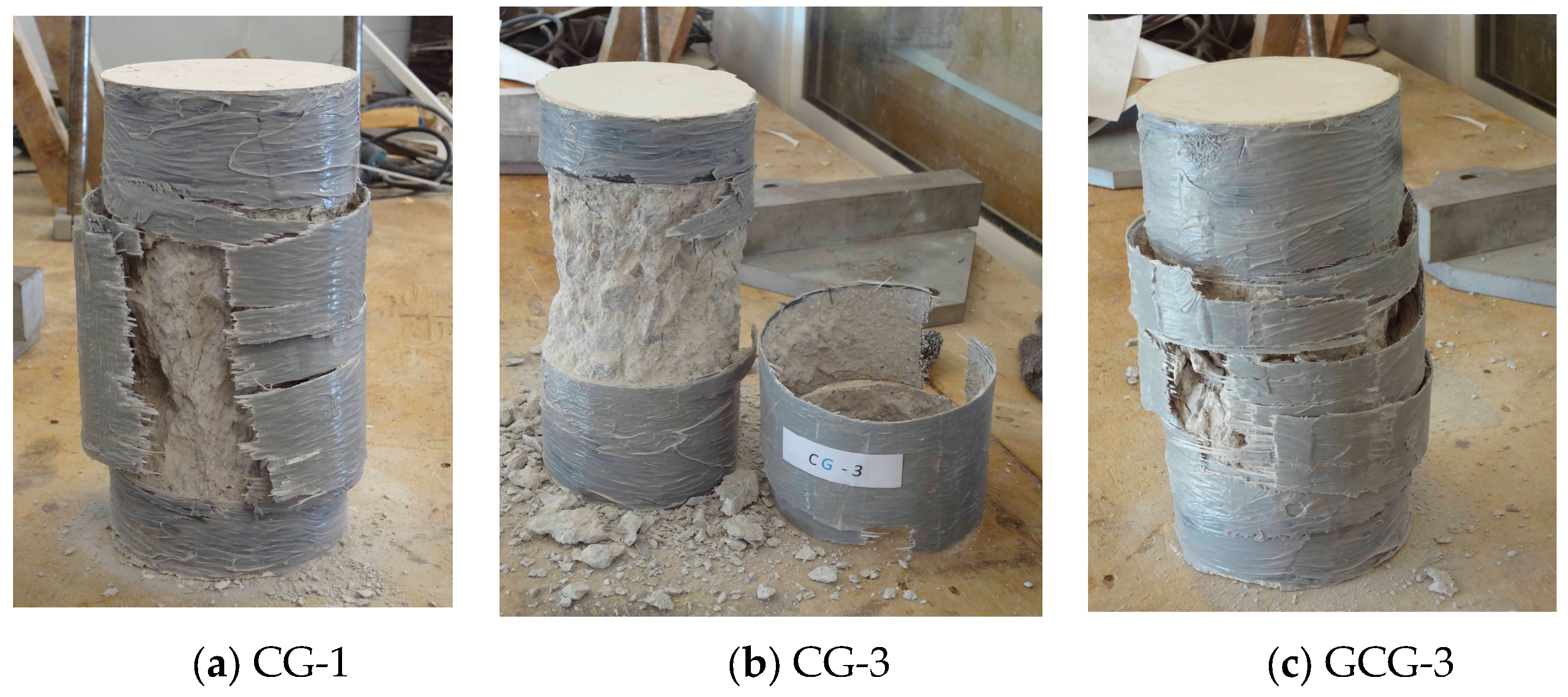
FRP jackets with fibers oriented along the hoop direction provide passive confinement of concrete, through the activation of the FRP forces in the hoop direction, fl, following the lateral expansion of concrete. Equilibrium of forces of the free body diagram shown in Figure 2 results in the relationship between the lateral confining pressure, fl, and the hoop stresses, ff, of the FRP, described by Equation (1) [4]. The effectiveness of the lateral confinement is expected to increase proportionately to the stiffness of the FRP jacket:
f l = 2 E f ε f t f D
where fl are the lateral confining stresses at the section level, Ef is the modulus of elasticity of the FRP, εf is the FRP strain, tf is the thickness of the FRP jacket, and D is the diameter of the column.
In order to better evaluate the confining properties of a jacket configuration, the volumetric response should also be examined. In a triaxial state of stress, the volumetric strain, εv, is calculated from Equation (2) [4]:
ε v = ε c + 2 ε l
where εv is the volumetric strain, εc is the axial strain, and εl is the lateral strain.

3.1. Failure Mode

Specimens with a simple CFRP jacket failed suddenly. The CFRP jacket ruptured, in general, along a vertical continuous line, as can be observed in Figure 3b,c.
In specimens with a simple GFRP jacket, the failure procedure was gradual and could be detected. When the axial load was about 70% of the peak value, sounds were heard attributed to local failure of GFRP fibers. The observed rupture surface of the FRP jacket was not along a single vertical line, as in the case of CFRP jackets, but in different locations in the hoop direction along the height, as shown in Figure 4.
In hybrid jackets, consisting of the combination of CFRP and GFRP sheets, as a rule, failure occurred in a more gradual manner compared to simple CFRP jackets. However, significant debonding between CFRP and GFRP sheets was observed in the case of specimens GC, GGC, and GCC, in which the more flexible GFRP sheet was located in contact with concrete, as shown in Figure 5. In this case, the CFRP jacket, with εfu = 1.8%, ruptured first, and the bond stresses at the interface between the two types of fiber sheets were not sufficient to sustain the shear stresses developed. Because of debonding, the failure surface of the GFRP sheets did not coincide in general to that of the CFRP sheets.
No debonding was observed in hybrid specimens CG, in which the CFRP jacket was placed in contact with concrete. The failure surface was along a vertical line, similar to that of CFRP specimens (Figure 6a,b) with noises precursor to FRP rupture, similar to GFRP jackets.
Also, no debonding was observed in the case of GCG specimens, in which the CFRP layer is between two GFRP layers. The jacket ruptured at different locations along the height, similar to simple GFRP jackets. Among the hybrid configurations tested, CGC jackets appeared to result in a more ductile type of failure.
The occurrence of debonding in the tests of this study may be partly attributed to the location of CFRP exteriorly to GFRP. Another factor might be the dry lay-up process used for manufacturing the specimens. It was established that in case of dry layout process, a comparatively increased maturing time, with respect to that prescribed by manufacturers, is required in order to avoid debonding at the overlap length of a jacket, contrary to the wet lay-up process [45].
Figure 3. Failure modes of specimens with one to three layers of CFRP jacket.
Fibers 13 00012 g003
Figure 4. Failure modes of specimens with one to three layers of GFRP jacket.
Fibers 13 00012 g004
Figure 5. Failure modes of hybrid specimens in which debonding was observed between different layers of FRP.
Fibers 13 00012 g005
Figure 6. Failure of hybrid specimens in which no debonding between different FRP layers occurred.
Fibers 13 00012 g006

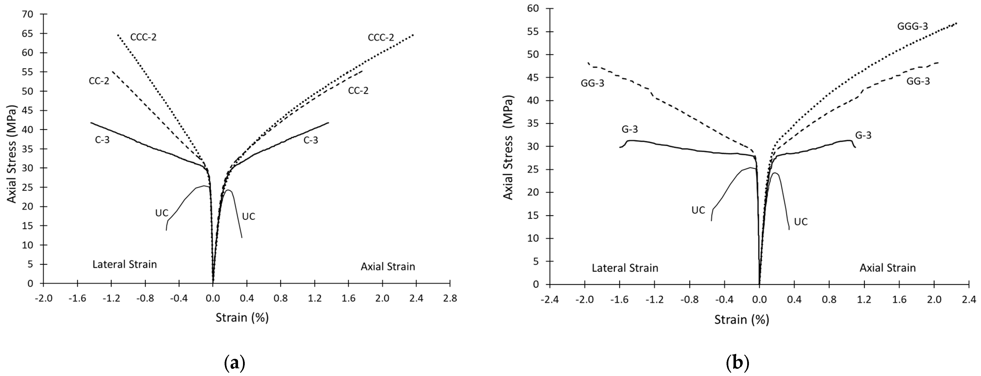
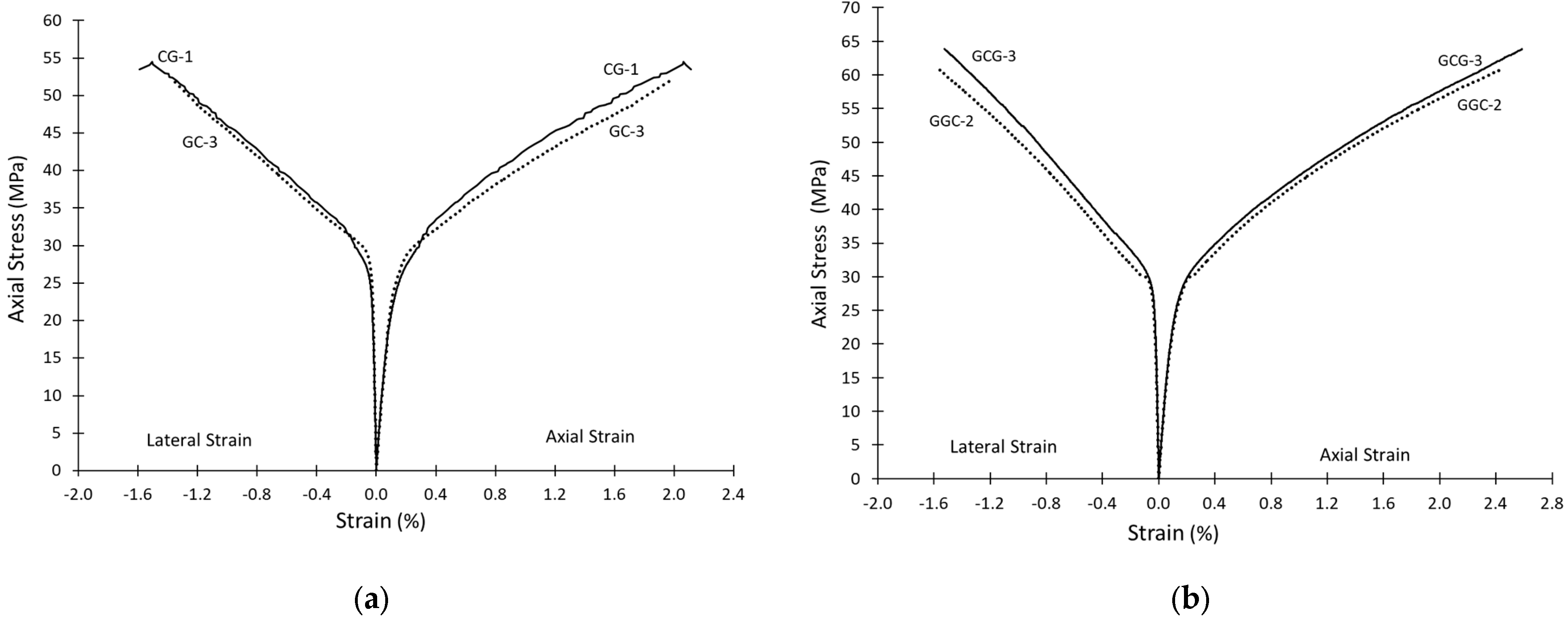
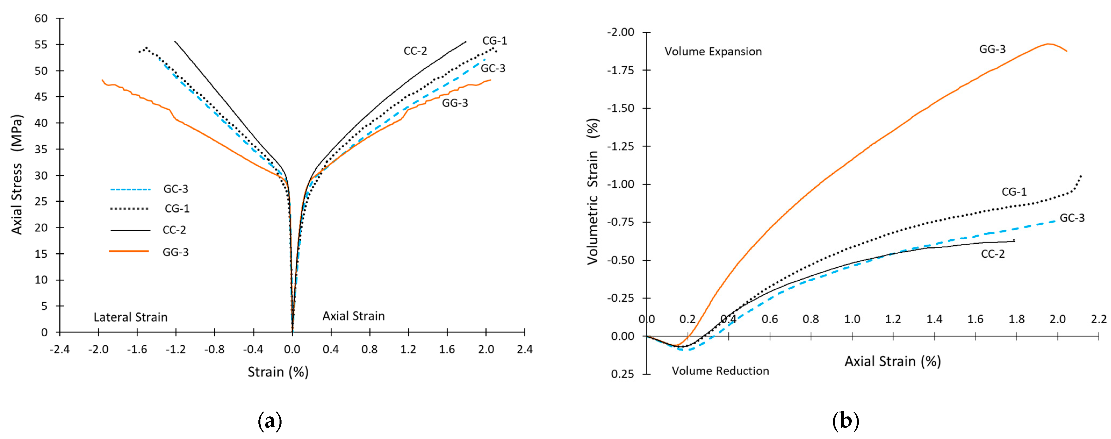
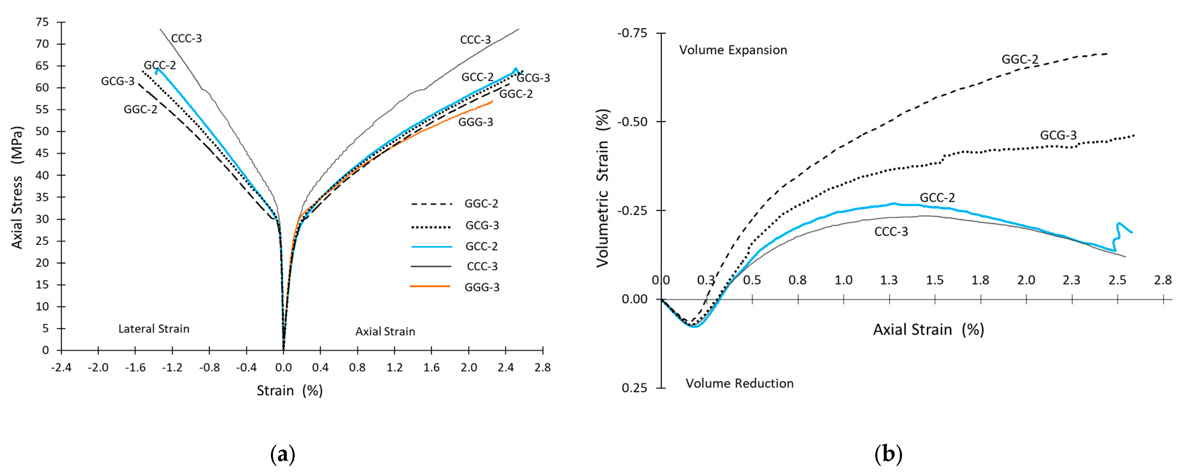
3.2. Axial Strength and Strain Relationships

Table 2 and Table 3 present the experimental results for the single-type FRP-jacketed specimens and the hybrid specimens, respectively. Only the specimens that did not fail prematurely because of un-strengthened ends are presented. The tables display the peak axial stress, fcu,exp, and the corresponding maximum axial and lateral strains, εcu,exp, and εlu,exp, respectively.
The experimental stress-strain curves are provided for each FRP configuration tested. Figure 7, Figure 8, Figure 9 and Figure 10 depict the curves of the axial stress against the lateral strains (on the left side of the chart) and the axial strains (on the right side of the chart) of typical configurations tested. The values of axial and lateral strains correspond to the measurements provided by the vertical and horizontal LVDTs situated in the testing rig shown in Figure 1c.
Figure 7a,b shows the stress-strain relationships of simple jackets with one to three layers of CFRP and GFRP, respectively. In both charts, the stress-strain curves of unconfined concrete (UC) are also depicted. As expected from Equation (1), for the same type of FRP, an increased number of layers in the jacket results in increased confinement and, hence, in enhancement in strength and deformation capacity. CFRP jackets result in increased peak axial stress as compared to specimens with similar layers of GFRP jacket because of the relatively increased stiffness of the CFRP jacket. It is noted that for specimens GGG the lateral displacements are not available because of malfunctioning of the LVDT.
Figure 8a displays the axial stress-strain curves for hybrid specimens CG and GC. Locating the CFRP jacket in contact with concrete in specimen CG-1 seems to result in a slightly more ductile behavior as compared to specimen GC-3, in which the CFRP jacket is the outer layer. Figure 8b compares the stress-strain relationship of hybrid specimens with three FRP jackets, i.e., two GFRP layers and one CFRP layer, but in a different stacking order. Specimen GCG-3, in which the CFRP layer is sandwiched between the GFRP layers, seems to result in an enhanced behavior, compared to specimen GGC-2, in which CFRP consists of the outer layer with two inner GFRP layers. It is noted that both hybrid FRP configurations, CG and GCG, which had a slightly better performance than their counterpart specimens (see Figure 8), ruptured without any debonding between consecutive FRP layers (Figure 6).
Figure 9a displays the axial stress-strain curves for the simple and hybrid specimens with two layers of FRP. According to the stress-strain curves, the most effective confinement in terms of axial strength is the jacket consisting of two CFRP layers, and the least effective is the jacket consisting of two GFRP layers, with the hybrid specimens having an intermediate performance. For the same specimens, Figure 9b shows the relationship between the axial strain and the volumetric strain calculated according to Equation (2). Comparison between the four specimens demonstrates that hybrid specimens GC-3 and CG-1 had a similar—though slightly inferior—confining performance, as compared to CC-2, in terms of overall volume reduction, in contrast with specimen GG-3, in which the stresses in the FRP jacket were not sufficient to curtail volume expansion.
Figure 10a,b displays the axial stress-strain curves and the axial-volumetric strain curves for the simple and hybrid specimens with three layers of FRP. According to the stress-strain curves, the most effective confinement is the jacket consisting of three CFRP layers, and the least effective is the jacket consisting of three GFRP layers, with the hybrid specimens having an intermediate performance. However, according to the volumetric-axial strain plots in Figure 10b, it may be observed that (a) hybrid specimen GCC-2 results in practically the same volume reduction as specimen CCC-3 for similar axial strains, and (b) the hoop stresses induced by both jackets achieve in curtailing volume expansion and in reversing its direction, leading to volume reduction. Furthermore, among GCG-3 and GGC-2 hybrid specimens, GCG-3 results in more volume reduction, though none of those FRP configurations sufficed to reverse volume expansion.
Table 4 displays the average values for peak axial strength, fcu,exp, and corresponding axial and lateral strains for the identical FRP configurations tested. The axial stiffness, Ef·tf, of each jacket, calculated as the sum of the stiffnesses of all jackets i E f i t f i , is also included in Table 4.
Figure 11a,b depicts the average ratios of peak confined axial strength and axial strain, normalized by the respective values of unconfined concrete. In both charts the axial stiffness of each jacket, Εf · tf, is also depicted.
Hybrid specimens CG and GC result in similar confined strength as specimen CC, to higher axial strain, εcu,exp, than CC (similar to specimen GG), while the value of the lateral strain, εlu,exp, is between the respective values of specimens CC and GG. Hybrid specimens GCG result in similar strength and slightly lower axial strain, εcu,exp, as compared to specimen GCC.
Regarding the stacking order of FRP layers, specimens CG and GCG perform slightly better than specimens GC and GGC, respectively. This observation is in contrast to the conclusion of Lin and Chen [22] that better performance is achieved when GFRP is located close to concrete. It is noted that in their tests on hybrid specimens, Ispir et al. [38] also placed the CFRP layer close to concrete, however, without having tested an alternative stacking order.

3.3. Lateral Strain Efficiency Factor of the FRP Jackets Tested

The ratio of the measured strain in the hoop direction at rupture of the FRP jackets, εlu,exp, to the FRP rupture strain, εfu, provided by the manufacturer, based on flat coupon tests, is known as the lateral strain efficiency factor, keff, derived from Equation (3) [46]. This factor is expected to be less than 1, owing to imperfections in the application procedure, occasional irregularities in the concrete substrate, the FRP overlap region, etc. [4,8,46,47,48]. The closer to unit this ratio is, the more profit of the FRP sheets for the confinement of concrete is made.
The value of εlu,exp, usually measured from strain gages along the mid-height section, has been found to vary considerably along the same section [49,50,51], and also among different researchers. In the present study, lateral strains, εlu,exp, correspond to the recordings of the lateral LVDT at peak load. Table 2 and Table 3 include the values εlu,exp of all the individual specimens, and Table 4 includes the average values, εlu,exp, between identical specimens, for each different FRP configuration studied.
To calculate the lateral strain efficiency ratio, keff, for the simple FRP jackets the rupture strain, εfu, is assumed to be equal to that provided by the manufacturer, i.e., for CFRP εfu = 0.0184 and for GFRP εfu = 0.0303 (see Table 1). For hybrid specimens εfu = 0.0184, it is assumed that rupture will be determined by the CFRP layer, which has smaller elongation capacity compared to GFRP. The ratios εlu,exp/εfu are shown in Table 2 and Table 3 for the simple and hybrid jackets. The averaged values, εlu,exp/εfu, for each FRP configuration are included in Table 4.
k e f f = ε l u , exp ε f u
It is observed that the presence of GFRP layers in hybrid specimens results in increased lateral expansion, which also causes enhanced activation of the included CFRP layer.

4. Analytical Predictions—Discussion

The most significant parameters in design models are the peak confined compressive stress, fcu, and the corresponding axial strain, εcu. Practically in all models, the confined concrete strength, fcu, is derived as a function of the lateral confining pressure, flf, induced by the FRP, as shown in Figure 1. Models differ in the values of the numerical parameters involved. Apparently different models may result in similar estimation of the confined concrete characteristics when applied to estimate test results, as has been pointed out by Moretti et al. [52], especially if they are calibrated against a large test database.

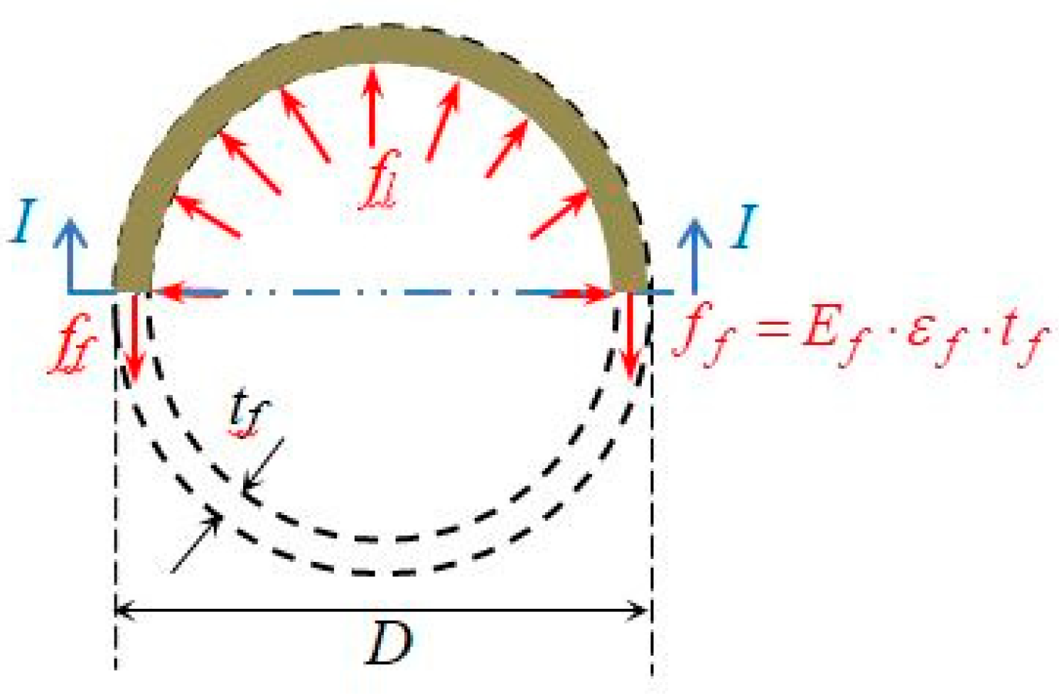
Proposed Design Model

In order to reliably estimate the peak confined concrete strength, fcu, and the corresponding axial strain, εcu, a number of models from the literature have been applied, including [8,53,54,55,56], all developed for FRP jackets with a simple type of fibers. The best predictions were obtained by the model of Wei and Wu [53], with εf = εfu as given from the manufacturer, i.e., keff = 1. It is noted that a number of available design models, e.g., [4,54,56], use a reduced strain of the FRP at failure, by adopting a lateral strain efficiency ratio (see Section 3.3), often the one that was obtained from their own tests. In the proposed model the confined compressive strength, fcu, is calculated according to Equation (4), where flu is the corresponding lateral confining pressure at failure and fco is the unconfined concrete strength.
f c u f c o = 0.5 + 2.7 f l u f c o 0.73
Lateral pressure, flu, for jackets consisting of a single type of FRP sheets is calculated from Equation (5a), where Ef is the FRP elastic modulus, εfu is the FRP strain at failure as provided by the manufacturer (keff = 1), tf is the total thickness of the jacket, and D is the section diameter.
f l u = 2 E f ε f u t f D
For hybrid jackets the use of Equation (5b) is proposed to determine flu. The contribution of the individual layers is added separately, because all layers in the jacket are assumed to have the same deformation, equal to the lateral deformation of concrete measured at mid-height of the specimen. The value of rupture strain, εfu, is assumed to be equal to that of CFRP, as provided from the manufacturer. The absence of slippage between the concrete and the epoxy polymer matrix prior to peak load validates this assumption:
f l u = 2 D i E f i t f i ε f u
where Efi and tfi are elastic modulus and the thickness of I FRP layer, and εfu is the minimum rupture strain of the FRPs in the jacket, as provided by the manufacturer.
It is noted that different approaches have been proposed by researchers to estimate the confining performance of hybrid FRP jackets. Ispir and Ilki [38] have applied a concept similar to the one proposed in this study.
The axial strain, εcu, that corresponds to peak compressive strength, fcu, for FRP confined circular sections with diameter D is calculated from Equation (6):
ε c u ε c o = 1.75 + 12 f l u f c o 0.75 f 30 f c o
where flu is the lateral pressure from the FRP, and it is calculated from Equation (5a) for simple jackets and (5b) for hybrid jackets; f30 = 30 Mpa; fco and εco are the concrete strength and the respective strain for the unconfined concrete.
It is pointed out that the proposed design model serves as a methodology to estimate the peak strength and strain concrete characteristics of the hybrid configurations tested. More experimental data are needed to verify its general applicability.
Table 5 displays the analytical values flu,anal, fcu,anal, εcu,anal calculated from the model for the different types of FRP jackets tested. The ratios of the predicted-to-experimental values for the axial strength and corresponding axial strain are also included. The experimental values are the averaged ones for each type of jacket (Table 4).
Figure 12 and Figure 13 display the ratios of the analytical-to-experimental confined compressive strength, fcu, and of the axial strain, εcu, respectively. It may be observed that for hybrid specimens, the model underestimates as a rule the experimental values because (a) the enhanced deformation capacity of the jacket, owing to the hybrid effect in the presence of GFRP, is not taken into account, and (b) FRP rupture strain was assumed equal to that of CFRP sheets.
For simple multilayered FRP jackets the model overestimates the experimental values, because the model does not account for the reduced confining performance of multiple FRP layers, as compared to a single FRP layer. If keff = 0.85 is used in the model for multiple layers in simple jackets for both types of FRP materials, i.e., for CC, CCC, GG, and GGG, the predicted ratios fcu,anal/fcu,exp and εcu,analcu,exp are improved, as may be observed from Figure 12 and Figure 13. It is noted that values keff = 0.60–0.85 have been often adopted by other researchers, e.g., [8,56], but without making any distinction in the number of layers in the FRP jacket, to the knowledge of the author.
It is interesting to observe that specimens GCC and GCG have similar axial strength, although GCC is supposed to profit 30% higher confining pressure, flu (see Table 5). Similarly, specimens CC and GC display similar experimental axial strength, although CC is supposed to profit 40% higher confining pressure, flu (see Table 5). In both cases the increased axial strength may be attributed to hybrid effect.
Table 6 and Table 7 compare the predictive performance of the proposed model, to that of three other design models among those considered, namely the models proposed by Wu and Wei, 2014 [54], Ilki and Kumbasar, 2003 [55], and Lam and Teng, 2003 [8]. The proposed model results in better predictions for the peak axial strength, fcu,exp, while for the axial strain, εcu,exp, the model has similar performance as the Ilki–Kumbasar model [55].
It is noted that use of keff = 0.85 for simple multilayered jackets (i.e., specimens CC, CCC, GG, GGG) results in safer predictions compared to keff = 1 (Figure 12 and Figure 13), which, however, is not reflected in the statistical indices.

5. Conclusions

The objective of this work was to study the compressive performance of hybrid jackets consisting of carbon- and glass-fiber-reinforced polymer jackets, CFRP and GFRP, respectively, in order to explore the potential of their application for the seismic retrofit of substandard RC columns. Based on the experimental results of 26 plain concrete cylinders wrapped with one to three layers of CFRP and GFRP with different stacking order, the basic conclusions drawn are summarized in the following.
The presence of GFRP layers in the hybrid specimens results in a more gradual and ductile failure, compared to the abrupt failure of simple CFRP jackets, and also entails increased lateral expansion at failure, which results in enhanced activation of the included CFRP layer. It was observed that substitution of one layer of CFRP by a layer of GFRP resulted in similar confined axial strength, compared to the respective specimens with more CFRP layers: Specimens GCC and GCG have similar axial strength, although GCC is supposed to benefit 30% higher lateral confining pressure. Similarly, specimens CC and GC displayed similar axial strength, despite the fact that CC is expected to have 40% higher confining pressure. In both cases, the increased axial strength may be attributed to the hybrid effect.
Regarding the stacking order of the FRP layers in the jacket, the location of the CFRP layer in contact with concrete proved to result in better performance, i.e., CG versus GC specimens. Furthermore, in three-layer jackets, the GFRP layer was more effective when it was sandwiched between CFRP layers, i.e., GCG versus GGC specimens.
The proposed design model results in good estimation of the confined concrete strength and axial deformation of the simple and hybrid jacketed specimens of this study.
The results of the present study demonstrate that the hybrid jackets tested could be particularly efficient for the retrofit of substandard RC frame columns as they are liable to reduce the risk of buckling of the longitudinal reinforcement on the one hand, and also to enhance ductility at the event of failure, by combining the stiffness provided by CFRP and the ductility attributed to GFRP. Further experimental work on RC columns is deemed necessary to verify those preliminary findings.

Funding

This research received no external funding.

Data Availability Statement

The data presented in this study are available on request from the author. The data are not publicly available due to privacy issues.

Acknowledgments

The tests were performed in the Laboratory of RC Structures in the department of civil engineering in the University of Thessaly, Volos. The contribution of George Karadimas (conceptualization of the test program and assistance in manufacturing of the specimens) and Emmanouil N. Kalogerakis (testing and processing of data results), in fulfillment of their undergraduate theses, is sincerely acknowledged. Materials used for the fabrication of the FRP jackets were donated by Sika Hellas ABEE. Technical support of Theocharis Papatheocharis (in carrying out the tests) and of the late Alekos Koutselinis (construction and jacketing of specimens) is duly acknowledged.

Conflicts of Interest

The author declares no conflicts of interest.

References

  1. Xiao, Y.; Wu, H. Compressive behavior of concrete confined by carbon fiber composite jackets. J. Mater. Civ. Eng. 2000, 12, 139–146. [Google Scholar] [CrossRef]
  2. Karabinis, A.I.; Rousakis, T.C. Concrete confined by FRP material a plasticity approach. Eng. Struct. 2002, 24, 923–932. [Google Scholar] [CrossRef]
  3. Tamuzs, V.; Tepfers, R.; Zile, E.; Ladnova, O. Behavior of concrete cylinders confined by a carbon composite: 3. Deformability and the ultimate axial strain. Mech. Compos. Mater. 2006, 42, 303–314. [Google Scholar] [CrossRef]
  4. Mirmiran, A.; Shahaway, M. Behavior of Concrete Columns Confined by Fiber Composites. J. Struct. Eng. 1997, 123, 583–590. [Google Scholar] [CrossRef]
  5. Ozbakkaloglu, T.; Saatcioglu, M. Seismic behavior of high-strength concrete columns confined by fiber reinforced polymer tubes. J. Compos. Constr. 2006, 10, 538–549. [Google Scholar] [CrossRef]
  6. Fam, A.Z.; Rizkalla, S.H. Flexural behavior of concrete-filled fiber reinforced polymer circular tubes. J. Compos. Constr. 2002, 6, 123–132. [Google Scholar] [CrossRef]
  7. Ozbakkaloglu, T.; Oehlers, D.J. Concrete-filled square and rectangular FRP tubes under axial compression. J. Compos. Constr. 2008, 12, 469–477. [Google Scholar] [CrossRef]
  8. Lam, L.; Teng, J.G. Design-oriented stress–strain model for FRP-confined concrete. Constr. Build. Mater. 2003, 17, 471–489. [Google Scholar] [CrossRef]
  9. Bisby, L.A.; Dent, A.J.S.; Green, M.F. Comparison of confinement models for fiber-reinforced polymer-wrapped concrete. ACI Struct. J. 2005, 102, 62–72. [Google Scholar]
  10. Teng, J.G.; Huang, Y.L.; Lam, L.; Ye, L.P. Theoretical model for fiber-reinforced polymer-confined concrete. J. Compos. Constr. 2007, 11, 201–210. [Google Scholar] [CrossRef]
  11. Teng, J.G.; Jiang, T.; Lam, L.; Luo, Y.Z. Refinement of a design-oriented model for FRP-confined concrete. J. Compos. Constr. 2009, 13, 269–278. [Google Scholar] [CrossRef]
  12. Jiang, J.G.; Teng, J.G. Analysis-oriented stress-strain models for FRP-confined concrete. Eng. Struct. 2007, 29, 2968–2986. [Google Scholar] [CrossRef]
  13. Realfonzo, R.; Napoli, A. Concrete confined by FRP systems: Confinement efficiency and design strength models. Compos. Part B 2011, 42, 736–755. [Google Scholar] [CrossRef]
  14. Ozbakkaloglu, T.; Lim, J.C.; Vincent, T. FRP-confined concrete in circular sections: Review and assessment of stress–strain models. Eng. Struct. 2013, 49, 1068–1088. [Google Scholar] [CrossRef]
  15. Hayashi, T. On the improvement of mechanical properties of composites by hybrid composition. In Proceedings of the 8th International Reinforced Plastics Conference, Brighton, UK, 10–12 October 1972; paper 22. pp. 149–152. [Google Scholar]
  16. Bunsell, A.R.; Harris, B. Hybrid carbon and glass fibre composites. Composites 1974, 5, 157–164. [Google Scholar] [CrossRef]
  17. Manders, P.W.; Bader, M.G. The strength of hybrid glass/carbon fibre composites. J. Mater. Sci. 1981, 16, 2233–2245. [Google Scholar] [CrossRef]
  18. Bakis, C.E.; Nanni, A.; Terosky, J.A.; Koeler, S.W. Self-monitoring, pseudo-ductile, hybrid FRP reinforcement rods for concrete applications. Compos. Sci. Technol. 2001, 61, 815–823. [Google Scholar] [CrossRef]
  19. Ribeiro, F.; Sena-Cruz, J.; Branco, F.G.; Júlio, E. Hybrid effect and pseudo-ductile behaviour of unidirectional interlayer hybrid FRP composites for civil engineering applications. Constr. Build. Mater. 2018, 171, 871–890. [Google Scholar] [CrossRef]
  20. Summerscales, J.; Short, D. Carbon fibre and glass fibre hybrid reinforced plastics. Composites 1978, 9, 157–166. [Google Scholar] [CrossRef]
  21. Swolfs, Y.; Gorbatikh, L.; Verpoest, I. Fibre hybridisation in polymer composites: A review. Compos. Part A Appl. Sci. Manuf. 2014, 67, 181–200. [Google Scholar] [CrossRef]
  22. Lin, H.J.; Chen, C.T. Strength of concrete cylinder. J. Reinf. Plast. Compos. 2001, 20, 1577–1600. [Google Scholar] [CrossRef]
  23. Wu, G.; Wu, Z.S.; Lu, Z.T.; Ando, Y.B. Structural performance of concrete confined with hybrid FRP composites. J. Reinf. Plast. Compos. 2008, 27, 1323–1348. [Google Scholar] [CrossRef]
  24. Tang, W.; Liu, Z.; Lu, Y.; Li, S. Hybrid confinement mechanism of large-small rupture strain FRP on concrete cylinder. J. Build. Eng. 2022, 51, 104335. [Google Scholar] [CrossRef]
  25. Jalalvand, M.; Czél, G.; Wisnom, M.R. Damage analysis of pseudo-ductile thin-ply UD hybrid composites—A new analytical method. Compos. Part A 2015, 69, 83–93. [Google Scholar] [CrossRef]
  26. Czél, G.; Wisnom, M.R. Demonstration of pseudo-ductility in high performance glass/epoxy composites by hybridisation with thin-ply carbon prepreg. Compos. Part A 2013, 52, 23–30. [Google Scholar] [CrossRef]
  27. Pandya, K.S.; Veerraju, C.; Naik, N.K. Hybrid composites made of carbon and glass woven fabrics under quasi-static loading. Mater. Des. 2011, 32, 4094–4099. [Google Scholar] [CrossRef]
  28. Czél, G.; Jalalvand, M.; Wisnom, M.R. Design and characterisation of advanced pseudo-ductile unidirectional thin-ply carbon/epoxy–glass/epoxy hybrid composites. Compos. Struct. 2016, 143, 362–370. [Google Scholar] [CrossRef]
  29. Wisnom, M.R. Mechanisms to create high performance pseudo-ductile composites. IOP Conf. Ser. Mater. Sci. Eng. 2016, 139, 012010. [Google Scholar] [CrossRef]
  30. Rousakis, T.C. Hybrid confinement of concrete by fiber-reinforced polymer sheets and fiber ropes under cyclic axial compressive loading. J. Compos. Constr. 2013, 17, 732–743. [Google Scholar] [CrossRef]
  31. Rousakis, T.C. Reusable and recyclable nonbonded composite tapes and ropes for concrete columns confinement. Compos. Part B 2016, 103, 15–22. [Google Scholar] [CrossRef]
  32. Rousakis, T.C. Inherent seismic resistance of RC columns externally confined with nonbonded composite ropes. Compos. Part B 2018, 135, 142–148. [Google Scholar] [CrossRef]
  33. Saingam, P.; Hussain, Q.; Ejaz, A.; Nawaz, A.; Joklad, P.; Khan, K. Enhancing compressive behavior of concrete with novel low-cost hybrid passive confinement including large rupture strain cotton ropes: Experimental findings and a design-oriented model. Case Stud. Constr. Mater. 2024, 21, e03496. [Google Scholar] [CrossRef]
  34. Wahab, N.; Srinophakun, P.; Hussain, Q.; Chaimahawan, P. Performance of concrete confined with a jute–polyester hybrid fiber reinforced polymer composite: A novel strengthening technique. Fibers 2019, 7, 72. [Google Scholar] [CrossRef]
  35. Farokhi Nejad, A.; Bin Salim, M.Y.; Rahimian Koloor, S.S.; Petrik, S.; Yahya, M.Y.; Abu Hassan, S.; Mohd Shah, M.K. Hybrid and synthetic FRP composites under different strain rates: A review. Polymers 2021, 13, 3400. [Google Scholar] [CrossRef]
  36. Joyklad, P.; Saingam, P.; Ali, N.; Ejaz, A.; Hussain, Q.; Khan, K.; Chaiyasarn, K. Low-Cost Fiber Chopped Strand Mat Composites for Compressive Stress and Strain Enhancement of Concrete Made with Brick Waste Aggregates. Polymers 2022, 14, 4714. [Google Scholar] [CrossRef]
  37. Bai, Y.-L.; Liu, S.-Z.; Mei, S.J. Compressive behavior and modeling of concrete wrapped by hybrid low-high elongation capacities FRP. Eng. Struct. 2024, 300, 117155. [Google Scholar] [CrossRef]
  38. Ispir, M.; Dalgic, K.D.; Iki, A. Hybrid confinement of concrete through use of low and high rupture strain FRP. Compos. Part B 2018, 153, 154–196. [Google Scholar] [CrossRef]
  39. Garcia, R.; Hajirasouliha, I.; Pilakoutas, K. Seismic behaviour of deficient RC frames strengthened with CFRP composites. Eng. Struct. 2004, 32, 3075–3085. [Google Scholar] [CrossRef]
  40. Garcia, R.; Jemaa, Y.; Helal, Y.; Guadagnini, M.; Pilakoutas, K. Seismic strengthening of severely damaged beam-column RC joints using CFRP. J. Compos. Constr. 2013, 18, 3075–3085. [Google Scholar] [CrossRef]
  41. De Luca, A.; Nardone, F.; Matta, F.; Nanni, A.; Lingnola, G.P.; Prota, A. Structural Evaluation of Full-Scale FRP-Confined Reinforced Concrete Columns. J. Compos. Constr. 2011, 15, 112–123. [Google Scholar] [CrossRef]
  42. Dai, J.G.; Lam, L.; Ueda, T. Seismic retrofit of square RC columns with polyethylene terephthalate (PET) fibre reinforced polymer composites. Constr. Build. Mater. 2012, 27, 206–217. [Google Scholar] [CrossRef]
  43. Moretti, M.L. Rapid retrofit of substandard short RC columns with buckled longitudinal bars using CFRP jacketing. Earthq. Struct. 2023, 24, 97–109. [Google Scholar] [CrossRef]
  44. Bai, Y.L.; Dai, J.G.; Teng, J.G. Cyclic compressive behavior of concrete confined with large rupture strain FRP composites. J. Compos. Constr. 2014, 18, 04013025. [Google Scholar] [CrossRef]
  45. Moretti, Μ.L.; Arvanitopoulos, E. Overlap length for confinement of carbon and glass FRP-jacketed concrete columns. Compos. Struct. 2018, 195, 14–25. [Google Scholar] [CrossRef]
  46. Pessiki, S.; Harries, K.A.; Kestner, J.; Sause, R.; Ricles, J.M. The axial behavior of concrete confined with fiber reinforced composite jackets. ASCE J. Compos. Constr. 2001, 5, 237–245. [Google Scholar] [CrossRef]
  47. Wu, Y.F.; Jiang, J.F. Effective strain of FRP for confined circular concrete columns. Compos. Struct. 2013, 95, 479–491. [Google Scholar] [CrossRef]
  48. Shahawy, M.; Mirmiran, A.; Beitelman, A. Test and modelling of carbon-wrapped concrete columns. Compos. Part B Eng. 2000, 31, 471–480. [Google Scholar] [CrossRef]
  49. Moretti, M.L. Effectiveness of different confining configurations of FRP jackets for concrete columns. Struct. Eng. Mech. Int. J. 2019, 72, 155–168. [Google Scholar] [CrossRef]
  50. Vincent, T.; Ozbakkaloglu, T. Influence of overlap configuration on compressive behavior of CFRP-confined normal- and high-strength concrete. Mater. Struct. 2016, 49, 1245–1268. [Google Scholar] [CrossRef]
  51. Lim, J.C.; Ozbakkaloglu, T. Hoop strains in FRP-confined concrete columns: Experimental observations. Mater. Struct. 2015, 48, 2839–2854. [Google Scholar] [CrossRef]
  52. Moretti, M.L.; Miliokas, E.; Paparizos, I. Axial strength estimation of reinforced concrete columns confined through fiber reinforced polymer (FRP) jackets. J. Multidiscip. Eng. Sci. Technol. 2021, 8, 13804–13818. Available online: https://www.jmest.org/wp-content/uploads/JMESTN42353721.pdf (accessed on 30 April 2021).
  53. Wei, Y.-Y.; Wu, Y.-F. Unified stress-strain model of concrete for FRP-confined columns. Constr. Build. Mater. 2012, 26, 381–392. [Google Scholar] [CrossRef]
  54. Wu, Y.F.; Wei, Y. General stress-strain model for steel- and FRP-confined concrete. J. Compos. Constr. 2014, 19, 04014069. [Google Scholar] [CrossRef]
  55. Ilki, A.; Kumbasar, N. Compressive behaviour of carbon fibre composite jacketed concrete with circular and non-circular cross-sections. J. Earthq. Eng. 2003, 7, 381–406. [Google Scholar] [CrossRef]
  56. Ilki, A.; Kumbasar, N.; Koc, V. Low strength concrete members externally confined with FRP sheets. Struct. Eng. Mech. 2004, 18, 167–194. [Google Scholar] [CrossRef]
Figure 1. (a) Elimination of loose particles from the concrete surface before the application of the FRP; (b) Final impregnation of the FRP jacket with epoxy; (c) Specimen inside the testing rig with LVDTs ready for testing.
Fibers 13 00012 g001
Figure 2. Confining action of an FRP-jacketed concrete circular column subjected to compression.
Fibers 13 00012 g002
Figure 7. Experimental curves depicting axial stress (in MPa) in the vertical axis versus axial and lateral strain in the horizontal axis for specimens with simple jackets: (a) Specimens with one to three layers of CFRP; (b) Specimens with one to three layers of GFRP. Note: UC corresponds to the control concrete specimens without FRP jacket.
Fibers 13 00012 g007
Figure 8. Experimental curves depicting axial stress (in MPa) in the vertical axis versus axial and lateral strain in the horizontal axis for specimens with hybrid jackets: (a) Specimens with one CFRP and one GFRP layer; (b) Specimens with two GFRP and one CFRP layer.
Fibers 13 00012 g008
Figure 9. Experimental stress-strain curves for specimens with two FRP layers in different configurations: (a) Curves depicting axial stress (in MPa) in the vertical axis versus axial and lateral strain in the horizontal axis; (b) Curves of volumetric stain in the vertical axis (calculated from Equation (2)) versus axial strain in the horizontal axis.
Fibers 13 00012 g009
Figure 10. Experimental stress-strain curves for specimens with three FRP layers in different configurations: (a) Curves depicting axial stress (in MPa) in the vertical axis versus axial and lateral strain in the horizontal axis; (b) Curves depicting the volumetric stain (calculated from Equation (2)) in vertical axis versus axial strain in horizontal axis.
Fibers 13 00012 g010
Figure 11. Average experimental values between identical specimens depicting on the left axis in bar charts: (a) Ratios of axial confined strength, fcu,exp, to the unconfined concrete strength fco; (b) Ratios of maximum axial strain, εcu,exp, to peak unconfined concrete stain, εco. The right axis in both figures displays in linear chart the axial stiffness Ef · tf (in N/mm) of each FRP jacket tested.
Fibers 13 00012 g011
Figure 12. Average ratios of analytical-to-experimental compressive strength, fcu,anal/fcu,exp, for keff = 1, for the configurations tested. The ratios calculated for analytical predictions using FRP stains at failure reduced by keff = 0.85 are separately indicated.
Fibers 13 00012 g012
Figure 13. Average ratios of analytical-to-experimental axial strain, εcu,analcu,exp, for keff = 1, for the configurations tested. The ratios calculated for analytical predictions using FRP stains at failure reduced by keff = 0.85 are separately indicated.
Fibers 13 00012 g013
Table 1. Mechanical properties of dry fiber sheets.
FRP TypeTensile Strength ffu
(MPa)
Tensile Modulus of Elasticity Ef (GPa)Fabric Design
Thickness, tf (mm)
Ultimate Strain εfu
(%)
Average Weight
gr/m2
carbon4300 MPa2340.1311.84230
glass2300 MPa760.1723.03445
Table 2. Test results of single-FRP-wrapped specimens.
Specimen fcu,exp (MPa)εcu,exp (%)εlu,exp (%)εlu,exp/εfu2
C-341.81.361.360.74
C-442.11.571.570.85
G-230.70.79N.A. 1N.A. 1
G-331.31.041.600.53
CC-255.61.791.210.66
CC-350.61.461.110.60
GG-146.61.851.830.60
GG-247.22.082.200.73
GG-348.22.041.960.65
CCC-264.92.381.130.61
CCC-373.42.541.330.72
GGG-153.51.71N.A. 1N.A. 1
GGG-357.12.26N.A. 1N.A. 1
1 not available; 2 εfu = rupture strain of fibers from the manufacturer, see Table 1.
Table 3. Test results of hybrid-FRP specimens.
Specimen fcu,exp (MPa)εcu,exp (%)εlu,exp (%)εlu,exp/εfu2
GC-252.01.771.290.70
GC-352.11.981.370.74
CG-153.52.121.590.86
CG-349.71.841.510.82
GCC-163.8N.A. 1N.A. 1 N.A. 1
GCC-263.62.581.380.75
GCC-361.72.201.310.71
GCG-161.22.161.610.88
GCG-263.01.91N.A. 1N.A. 1
CCG-363.82.591.520.83
GGC-160.32.301.620.88
GGC-260.92.441.560.85
GGC-357.72.181.410.77
1 not available; 2 εfu = rupture strain of CFRP fibers from the manufacturer.
Table 4. Experimental average numerical values of identical simple and hybrid-FRP specimens.
Specimenfcu,exp (MPa)fcu,exp/fcoεcu,exp (%)εcu,exp/εcoεlu,exp (%)εlu,exp/εfu(2a.2b)Εf · tf
(N/mm)
C 42.01.711.478.141.470.8030,654
G 31.01.270.925.081.600.5313,072
CC 53.12.171.639.031.160.6361,308
GG 47.31.931.9911.312.000.6626,144
CCC 69.22.822.4613.671.230.6791,962
GGG 55.32.261.9911.03N.A. 1N.A. 139,216
GC 52.12.121.8810.421.330.7243,726
CG51.62.111.9811.001.550.8443,726
GCC 63.02.572.3913.281.35 0.7374,380
GCG 62.72.562.2212.331.570.8556,798
GGC 59.62.432.3112.811.530.8356,798
1 not available; 2a for simple jackets εfu = rupture strain of fibers from the manufacturer; 2b for hybrid jackets εfu = rupture strain of CFRP fibers from the manufacturer; fco = 24.5 MPa is the unconfined concrete strength; εco = 0.018 is the axial strain corresponding to fco of the unconfined concrete.
Table 5. Model predictions for the average numerical values of identical specimens.
Specimen flu,anal
(MPa)
fcu,anal (MPa)fcu,anal/
fcu,exp
εcu,anal
(%)
εcu,anal/
εcu,exp
C 7.4239.90.951.290.88
G 5.2133.61.081.061.16
CC 14.8458.11.091.951.20
GG 10.4247.71.001.570.79
CCC 22.2673.91.072.541.03
GGG 15.6359.91.082.021.02
GC 10.5848.10.921.580.84
CG 10.5848.10.931.580.80
GCC 18.0465.21.032.210.93
GCG 13.7455.60.891.860.84
GGC 13.7455.60.931.860.81
flu,anal: lateral pressure calculated from Equations (5a) and (5b) for simple and hybrid jackets, respectively; fcu,anal: analytical confined concrete strength from Equation (4); εcu,anal: analytical peak axial strain from Equation (6); fco, εco: are the concrete strength and the respective strain for the unconfined concrete.
Table 6. Validation of models’ predictive performance regarding the ultimate axial strength, fcu,anal.
Model
keff = 0.85 (5)
Model
keff = 1
Wu and Wei
(2014) [54]
Ilki–Kumbasar (2003) [55]Lam and Teng (2003) [8]
Average (1) (fcu,anal/fcu,exp)i 0.9711.041.070.94
STDEV (2) [fcu,anal/fcu,exp]0.060.080.090.090.09
MAE (3) Σ[abs(fcu,anal − fcu,exp)/n]2.893.654.404.254.46
Δ (4) [(fcu,exp − fcu,anal)/fcu,exp]0.380−0.43−0.750.70
(1) Average = sum of values/number of values: Σ(fcu,anal/fcu,exp)i/n; (2) STDEV = standard deviation of ratios [fcu,anal/fcu,exp]; (3) MAE = mean absolute error [abs(fcu,anal − fcu,exp)/n]; (4) Δ (average deviation) = [(fcu,exp − fcu,anal)/fcu,exp]; (5) keff = 0.85 used to reduce εfu in case of specimens CC, CCC, GG, GGG, as explained above; where: fcu,exp = peak axial stress at the test; fcu,anal = analytical confined concrete strength from Equation (4); n = number of averaged identical FRP configurations tested.
Table 7. Validation of the models’ predictive performance regarding the ultimate axial stain, εcu,anal.
Model
keff = 0.85 (5)
Model
keff = 1
Wu and Wei (2014) [54]Ilki–Kumbasar (2003) [55]Lam and Teng (2003) [8]
Average (1)cu,analcu,exp)i 0.900.942.800.940.98
STDEV (2)cu,analcu,exp]0.130.150.660.150.20
MAE (3) Σ[abs(εcu,anal − εcu,exp)/n]0.280.263.460.260.33
Δ (4) [(εcu,exp − εcu,anal)/εcu,exp]1.110.71−19.780.670.26
(1) Average = sum of values/number of values: Σ(εcu,analcu,exp)i/n; (2) STDEV = standard deviation of ratios [εcu,analcu,exp]; (3) MAE = mean absolute error [abs(εcu,anal − εcu,exp)/n]; (4) Δ (average deviation) = [(εcu,exp − εcu,anal)/εcu,exp]; (5) keff = 0.85 used to reduce εfu in case of specimens CC, CCC, GG, GGG, as explained above; where: εcu,exp = peak axial strain at the test; εcu,anal = analytical peak axial strain from Equation (6); n = number of averaged identical FRP configurations tested.
Disclaimer/Publisher’s Note: The statements, opinions and data contained in all publications are solely those of the individual author(s) and contributor(s) and not of MDPI and/or the editor(s). MDPI and/or the editor(s) disclaim responsibility for any injury to people or property resulting from any ideas, methods, instructions or products referred to in the content.

