Highlights
What are the main findings?
- Increasing the polypropylene fiber content from 8 kg/m3 to 12 kg/m3 significantly enhances both post-cracking flexural and shear strength.
- Larger initial crack openings reduce shear transfer efficiency, highlighting the critical role of fibers in maintaining stress transmission across cracks.
What is the implication of the main findings?
- Polypropylene macro-fibers with properties equivalent to those used in this study (at doses above 8 kg/m3) show strong potential to improve shear performance in structural applications.
- The established correlations between normal and shear stresses, slip, and crack width provide a solid foundation for constitutive modeling of cracks in polypropylene fiber-reinforced concrete.
Abstract
The objective of this study is to investigate the effects of macrosynthetic polypropylene fibres as shear reinforcement in a concrete crack. An experimental study was conducted using twenty push-off specimens with varying volumes of fibres, along with plain concrete specimens as a reference. The testing methodology allowed for the analysis of crack kinematics by measuring the evolution of normal and shear stresses in relation to slip and crack opening. This facilitated the creation of diagrams similar to those presented by Walraven (1980) for crack interface shear transfer, but in this case, applied to concrete reinforced with macrosynthetic polypropylene fibres. The findings demonstrate that macrosynthetic polypropylene fibres significantly enhance shear behaviour, particularly when their volume exceeds 8 kg/m3. This study provides valuable insights into the behaviour of macrosynthetic polypropylene fibres under shear loading conditions and highlights their potential benefits as effective shear reinforcement.
1. Introduction
Shear failure is considered one of the most critical modes of failure in concrete structures, particularly in elements without shear reinforcement. As a result, extensive research efforts have been dedicated to the examination of shear behaviour in concrete elements since as early as 1955. Despite the considerable advancements in the understanding of this subject matter, shear behaviour continues to be studied at present by the research community for both fibre-reinforced concrete (FRC) and reinforced concrete (RC).
Regarding the use of fibres in concrete for shear reinforcement, most of the research in this field has focused on steel fibres. Based on experimental findings, it is widely acknowledged that steel fibres are employed to increase both the shear capacity and post-cracking tensile strength of concrete. This enhancement in toughness in FRC is attributed to the bridging effects facilitated by steel fibres [1]. Steel fibres also provide substantial post-peak resistance and ductility [1,2,3] and can convert brittle modes of failure into ductile ones [3,4,5,6].
Recent publications have also highlighted [6,7] the effectiveness of macrosynthetic fibres, particularly polypropylene, for use as shear reinforcement in structural elements. While these studies undeniably signify advancements in our understanding of shear behaviour in elements reinforced with macrosynthetic fibres, certain questions remain unanswered.
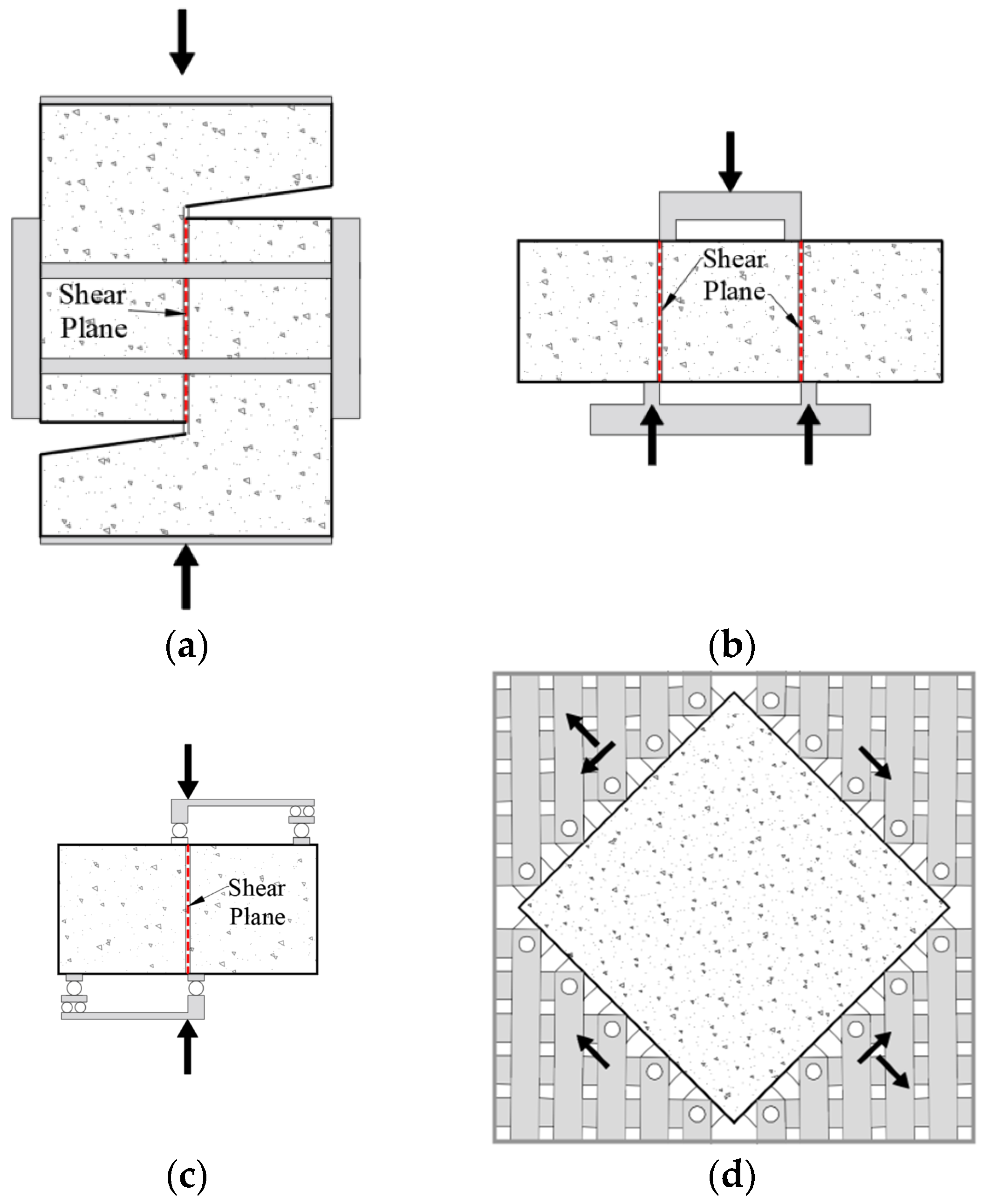
Shear force typically occurs in combination with other forces, such as bending moments or axial forces. To isolate and analyse the specific effects of shear independently of these other mechanisms, researchers have conducted experiments using small specimens, which have been reported in the literature. Most of these procedures are not standardised, making it challenging to replicate the tests. These tests commonly aim to determine Mode II fracture characteristics, shear strength, crack behaviour, aggregate interlock behaviour, or shear strain in several types of concrete, whether they contain fibres or not. The most frequent specimens and test procedures are presented in Figure 1.
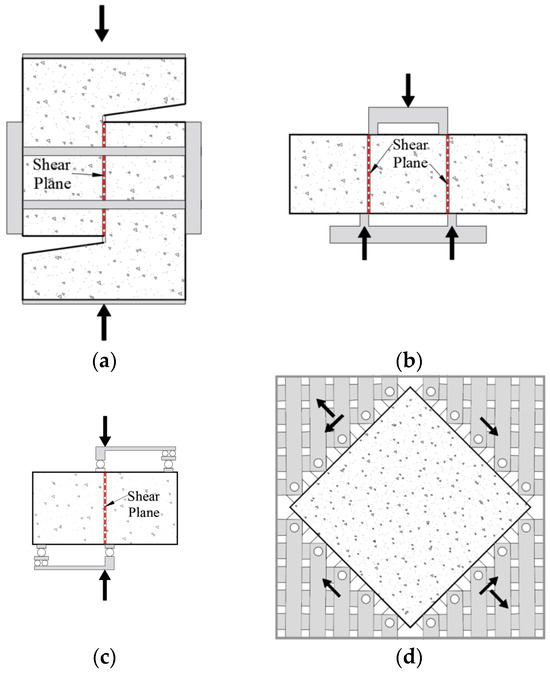
Figure 1.
Direct shear test: push-off test (a), JSCE test (b), FIP shear test (c), and panel test (d).
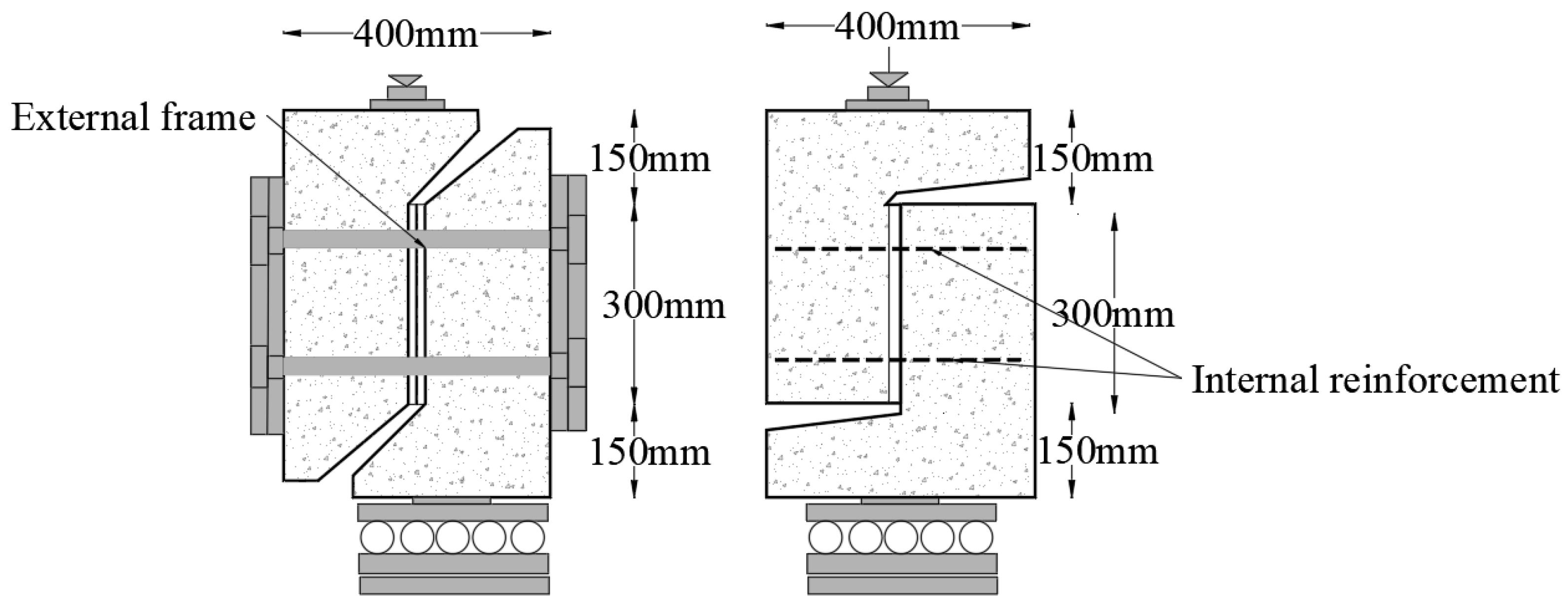
Some of the most renowned studies that use the push-off tests in reinforced concrete (RC) are those presented by Walraven and Reinhardt [8]. These tests focused on the investigation of pure aggregate interlocking within pre-cracked concrete push-off specimens. The variables of the test were concrete compressive strength, maximum gravel size, restraint stiffness, and initial crack width. Restraint stiffness was provided in some specimens by a rigid external frame, as Figure 2 shows. In certain push-off tests, the crack opening was constrained through the inclusion of internal reinforcement bars crossing the crack plane. It is important to note that in this type of test, it is assumed that shear stress remains uniform along the crack plane. Nevertheless, it is worth acknowledging that some small bending in the L-shaped specimen and rotational effects may be present during the test. Walraven recorded the crack opening and slip, and the shear and normal stresses.
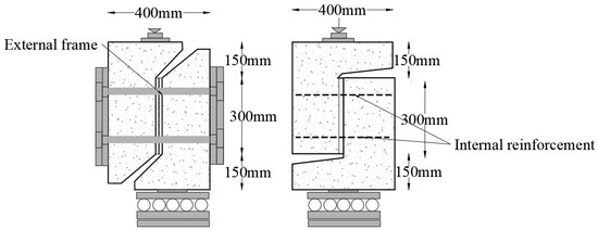
Figure 2.
Test specimens with external restraint frame and reinforced cracks (Adapted from [9]).
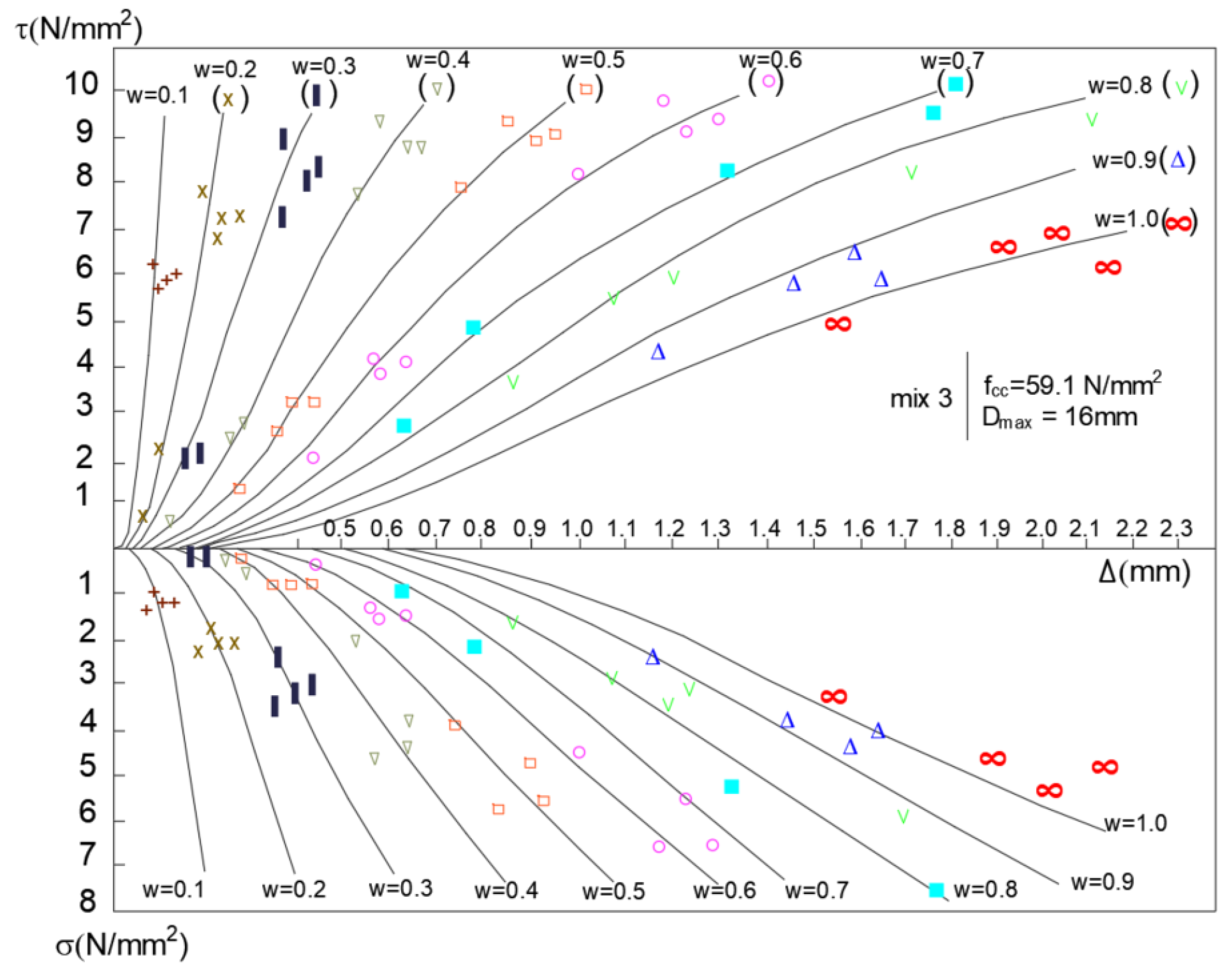
Walraven considered that concrete is represented by two main phases: the first is a matrix, and the second is the aggregate particles embedded in the matrix. In addition, the contact areas between the two phases correspond to the weakest link of the system. Therefore, cracking occurs through the matrix. Taking into account these considerations and assuming that aggregate particles are spheres, Walraven was able to develop a model that relates crack displacement and slip with stress (normal and tangential). The model, known as the Two-Phase Model (TPM), was validated with experimental results, as shown in Figure 3, where dots represent the experimental results and the curved lines represent the theoretical model. The TPM has been used to develop and calibrate new types of models to explain the shear transfer mechanism [9,10,11].
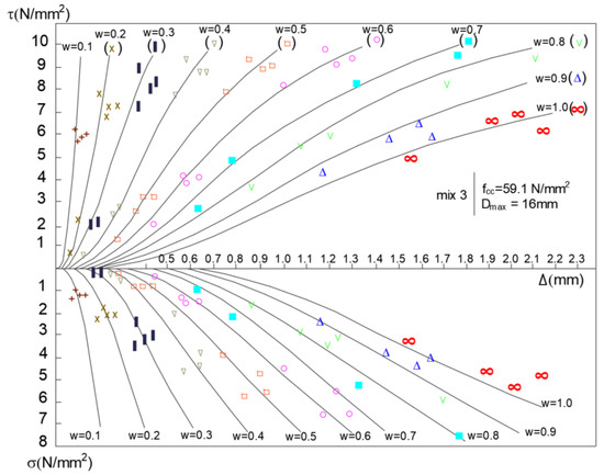
Figure 3.
Relationship between shear and normal stress in concrete cracks for different crack openings (Δ) according to the Walraven model (Adapted from [9]).
Similarly to RC, the shear behaviour of fibre-reinforced concrete has been studied using push-off tests. In 1987, Van de Loock [12] conducted experiments involving pre-cracked push-off specimens of SFRC to analyse the bridging effect provided by fibres. To maintain precise control over crack propagation, an external frame was employed to restrict the specimens, as in Walraven’s tests. The steel fibres were hook-ended, with a diameter of 0.8 mm and a length of 60 mm. The base material used was conventional concrete with a concrete compressive strength of 35 MPa. Prior to the push-off test, controlled crack initiation was executed, ensuring crack openings in the range of 0.015 mm to 0.02 mm.
The variables studied encompassed fibre content and the influence of external confinement. Notably, Van de Loock’s observations revealed a direct correlation between increased fibre content and enhanced shear strength. Furthermore, it was discerned that the influence of fibres on shear behaviour diminished as external confinement was heightened. Similar results were obtained by Balaguru and Dipsia [13] in 1993, when SFRC push-off specimens without external confinement were tested.
In 2006, Barragan et al. [14] conducted a comprehensive study on shear failure in push-off specimens derived from prismatic beams that had previously undergone bending tests. Barragan’s observations revealed that steel fibres exhibited a remarkable ability to restrict the expansion of tensile cracks in specimens containing SFRC as opposed to those with PC.
In 2014, at the Universitat Politècnica de Valencia, Echegaray [15] made modifications to the push-off test methodology proposed by Cuenca and Serna [16] for the purpose of analysing the shear behaviour of concrete cracks in both PC and SFRC. This revamped methodology involved two distinct stages: the pre-crack test and the direct shear test. To control crack propagation, specimens were securely encased within an external rigid steel frame. Ahead of the direct shear test, initial crack openings were precisely controlled by the placement of nuts on the bars forming the external frame.
Regarding polypropylene fibre-reinforced concrete (PFRC), in 2019, Picazo et al. [17,18] conducted an extensive evaluation to study the concrete’s shear behaviour using PFRC push-off specimens. Three types of concrete, several concrete compressive strengths, and two types of polypropylene fibres were the variables studied. Similarly to Barragan et al.’s approach [14], these push-off specimens were derived from small beams measuring 150 × 150 × 600 mm, which had previously been subjected to testing according to EN 14651 standards [19]. The findings indicated an increase in shear strength, although the post-cracking shear behaviour remained consistent across all concrete types. This uniformity may be attributed to the substantial significance of aggregate interlocking, further underscored by the consistent utilisation of a maximum aggregate size of 12.7 mm in all concrete mixtures.
In 2016, Majdzadeh et al. [20] conducted an experimental study focusing on PFRC. They assessed the performance of two synthetic fibre types and one steel fibre type under direct shear using JSCE-SF6 [21] with certain modifications. Majdzadeh compared the effectiveness of steel fibres in equal quantity to synthetic fibres as shear reinforcement. Their findings, comparable to those of other authors [22,23,24], indicated that steel fibres outperformed synthetic fibres in shear strength.
An alternative testing method for evaluating shear behaviour is the FIP shear test [25], which involves an asymmetric four-point test configuration. In this test, the loading point is strategically positioned to minimise bending effects, ensuring that the moments are zero on the crack plane. However, it is worth noting that the use of the FIP shear test for studying shear behaviour is relatively limited in the existing literature, as demonstrated in the work of Khanlou et al. in 2012 [26].
In all of these test setups, including push-off tests, JSCE shear tests, and FIP shear tests, the specimens are either pre-cracked or notched to establish a well-defined crack plane. However, despite the methodologies’ efforts to separate shear stress from other stress factors, the tests still do not achieve pure shear conditions. An alternative approach to obtain pure shear is the panel test, which eliminates the need for pre-cracking the specimen. The shear panel test was first developed at the University of Toronto in the 1980s by Vecchio and Collins, and has served to formulate one of the most accepted theories on shear in concrete [11]. An interesting example of panel tests concerning FRC can be found in the work of Susetyo et al. [27], where they investigated the effectiveness of steel fibres as minimal reinforcement for SFRC panels under monolithic loading conditions. Ten concrete panels measuring 890 mm × 890 mm × 70 mm were subjected to in-plane pure shear monotonic loading. The test results demonstrated that by appropriately incorporating steel fibres, it is possible to achieve concrete elements with ductile behaviour, higher shear strength, and effective crack control characteristics. Employing this type of shear panel, Seong-Cheol Lee [28] proposed a rational analysis procedure for modelling the shear behaviour of SFRC elements based on the Diverse Embedment Model [29,30].
In 2023, Gehri et al. [31] conducted an experimental procedure involving six large-scale fibre-reinforced concrete shear panels. These panels, measuring 2.00 m × 2.00 m × 0.27 m, underwent testing at ETH Zurich, subjected to uniform shear loading. The test results demonstrated the effectiveness of using fibres as shear reinforcement in substantial web elements. Notably, an increase in load capacity following the initiation of cracking was observed in all experiments. The authors also concluded that substituting conventional minimum shear reinforcement with fibres is advisable only when the presence of distributed cracks is assured.
On the other hand, only one experimental procedure has utilised shear panels made of macrosynthetic fibre-reinforced concrete. Unlike panels containing steel fibres, those reinforced with macrosynthetic fibres exhibited a higher incidence of distributed cracking in the panel specimens. Nonetheless, there was no significant alteration observed in the shear strengths of the panels compared to those reinforced with traditional concrete [32].
Within this framework, the present study aims to assess the effectiveness of enhancing the shear strength of concrete elements by employing polypropylene fibres distributed in the concrete. More specifically, this paper aims to study the influence of polypropylene fibres on the kinematic behaviour of an open concrete crack subjected to shear and normal stresses. To achieve this, the experimental study centres around a push-off type experimental protocol, designed to examine the kinematic behaviour of open cracks and establish relationships between normal and shear stresses in terms of crack slip and crack opening, drawing inspiration from the renowned aggregate interlock studies conducted by Walraven in 1980 [9]. The experimental results will serve as baseline data for calibrating constitutive models to explain the behaviour of concrete cracks reinforced with macrosynthetic polypropylene fibres.
2. Experimental Protocol
2.1. Material Properties
Prior to assessing the shear behaviour along a crack in PFRC, an extensive investigation was conducted to characterise the material properties. This procedure aimed to determine the compressive and flexural strengths of the concrete, as well as its post-cracking behaviour.
To provide a comprehensive overview, the proportions utilised for each type of concrete are presented in Table 1. Both the concrete and the specimens were produced at the ICITECH laboratory. The concrete is composed of Portland cement type CEM I 42.5 N, two types of gravel, two types of sand, and limestone filler, as outlined in Table 1. The maximum aggregate size employed was 14 mm. To assess the impact of fibre content on the concrete, two doses of fibres were employed: 8 kg/m3 (referred to as PFRC8) and 12 kg/m3 (referred to as PFRC12). While the main components were consistent in both PC and PFRC8, certain adjustments were made to PFRC12 to enhance concrete workability. The mix design for both PC and PFRC was formulated to achieve a characteristic concrete compressive strength of 40 MPa. Subsequently, all specimens were cast indoors and cured in a chamber with a temperature of 20 °C and 100% humidity.

Table 1.
Proportion of components of employed concretes.
In this experimental protocol, macrosynthetic fibres 48 mm in length were used, with a nominal aspect ratio (length/diameter) of 57, a density of 0.91 g/cm3, a tensile strength of 400 MPa, and a modulus of elasticity of 4.7 GPa.
To evaluate the concrete’s compressive and flexural strengths and post-cracking behaviour, a total of 28 cylindrical specimens (150 × 300 mm2) and 28 prismatic beams (150 × 150 × 600 mm3) were manufactured alongside the twenty push-off specimens. These specimens were cured under the same environmental conditions as the push-off specimens.
The compressive strength of the concrete was determined using cylindrical samples (fc) and cubic samples (fc,cube) in accordance with the EN 12390-3 [33] standard. The flexural strength (fL) and residual flexural tensile strength (fRj) for j = 0, 1, 2, 3 or 4, i.e., for CMOD (crack mouth opening displacement) values of 0.5, 1.5, 2.5, and 3.5 mm, were obtained for each concrete type (8 for PC, 15 for PFRC) following the EN 14651 [19] standard. The CMOD values were measured using PTs placed beneath the specimen. The average mechanical properties of each concrete, along with the coefficient of variation (in brackets), are presented in Table 2. These mechanical properties were determined 28 days after casting the specimens.
Table 2.
Mechanical properties of PC and PFRC.
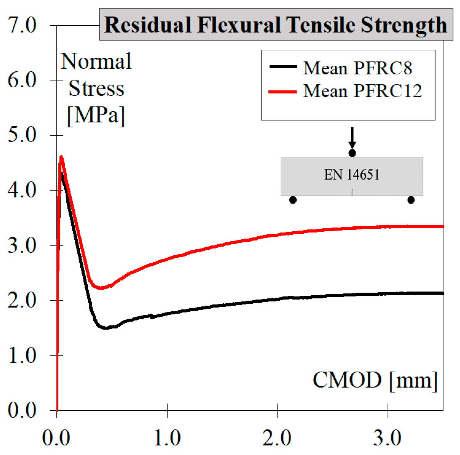
Figure 4 illustrates the relationship between normal stress and CMOD response for the PFRC beam specimens in accordance with EN 14651. It is worth noting that an increase in fibre content from 8 to 12 kg/m3 led to an increase in residual flexural tensile strength. The flexural toughness, measured from CMOD = 0.5 mm to 3.5 mm, for PFRC8 and PFRC12 (represented by the area under the curve) was 5.88 MPa·mm and 9.22 MPa·mm, respectively.
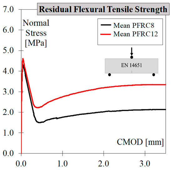
Figure 4.
Nominal stress–CMOD responses according to EN 14651 [19].
2.2. Test Specimens
To investigate the factors influencing shear transfer mechanisms in a PFRC crack, direct shear tests on twenty pre-cracked PC and PFRC push-off specimens were performed. The testing procedure adhered to the methodology proposed by Echegaray et al. [15], which effectively monitors crack kinematics throughout all stages of the test, including assembly, pre-cracking, handling, and push-off. For more comprehensive information, please refer to Section 2.3.
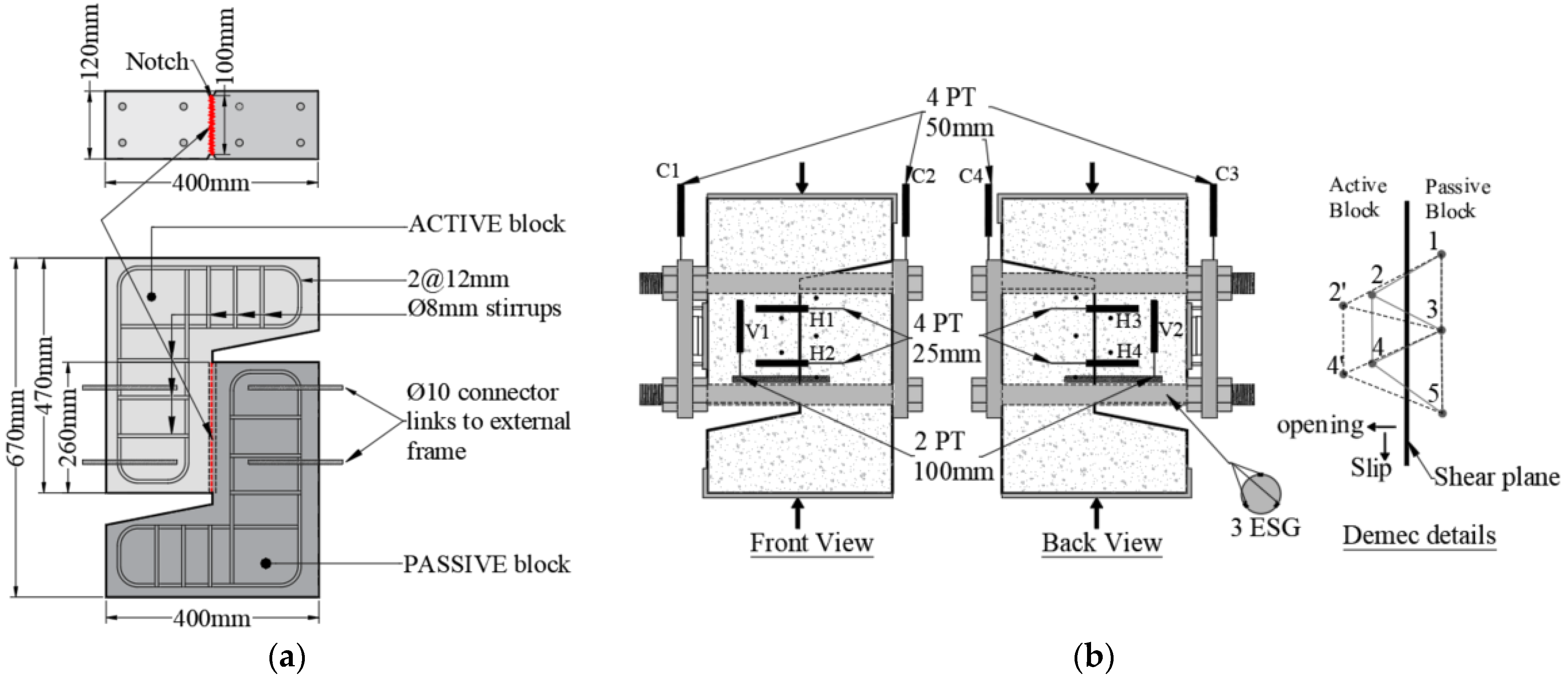
To achieve this objective, 4 specimens were prepared using PC and 16 using PFRC. Among the PFRC specimens, 8 had a fibre content of 8 kg/m3, while the remaining 8 had a fibre content of 12 kg/m3 using macrosynthetic fibres. The push-off specimens were designed with the geometry and reinforcement configuration illustrated in Figure 5a. The concrete mix was prepared in a planetary mixer. Four push-off specimens were cast per batch, along with companion specimens for the characterisation of compressive strength and residual flexural tensile strength. The mixing process involved the incorporation of conventional concrete materials together with the mixing water. Subsequently, the superplasticiser admixture was added, and once the mix reached the desired consistency, the fibres were introduced manually, taking care to avoid the formation of fibre clumps (commonly known as “hedgehogs”). To ensure proper compaction, vibration was applied at the ends of the specimen (outside the shear plane) to avoid disturbing the random alignment of fibres within the shear plane.
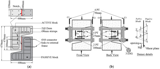
Figure 5.
Push-off test. (a) Geometry and reinforcement details. (b) Instrumentation.
The experimental variables investigated in this study encompass concrete type (PC and PFRC), fibre content (8 and 12 kg/m3), and the effect of confinement on shear behaviour. To evaluate this, different crack gaps were initially introduced into the specimens: W = 0.0, 0.2, and 0.4 mm for the PC specimens, and W = 0.0, 0.2, 0.4, and 0.6 mm for the PFRC specimens. Crack gaps and the kinematics of the cracks were recorded during the test by means of LVDTs and DEMEC discs, as shown in Figure 5b. In most cases, two specimens were tested for each crack gap (W) value within the PFRC group.
2.3. Test Setup and Instrumentation
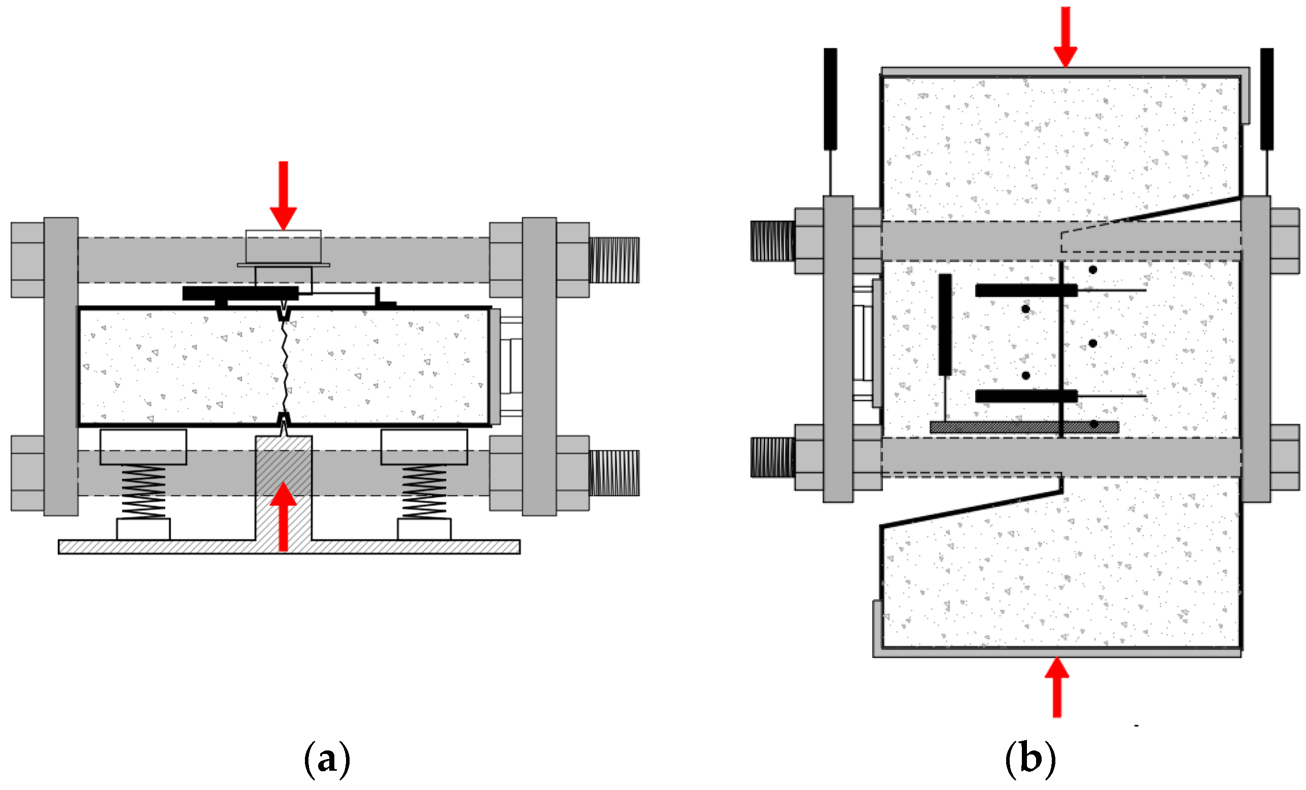
As mentioned before, the push-off tests were conducted in four distinct stages: (a) frame assembly, (b) pre-cracking (see Figure 6a), (c) handling, and (d) push-off test (see Figure 6b). These stages were performed following the test methodology established by Echegaray et al. [15]. To ensure comprehensive traceability and facilitate a clear understanding of the testing procedure, specific details of this push-off testing procedure are included.

Figure 6.
Test setup: (a) pre-cracking process and (b) push-off test.
Frame assembly (a): In this stage, the nuts were adjusted to achieve an average strain of 26 microstrains on each bar. This strain was employed to introduce an initial confinement (σini) of approximately 0.7 MPa into each specimen. It is important to note that this strain value differs from Echegaray’s methodology, which utilised an average strain of 0.015 microstrains on each bar, resulting in σini ranging from less than 0.01 MPa to 0.7 MPa. By introducing this change, the confinement (σ0) prior to the push-off test became positive, indicating complete confinement of the specimen regardless of the initial crack opening. The initial confinements of the tested specimens are summarised in Table 3. The frame assembly process concluded with the measurement of the separation among the DEMEC targets before proceeding to the pre-cracking stage.
Table 3.
Initial crack state for tested specimens.
The pre-cracking process (b) and handling (c) followed Echegaray’s methodology [15]. For the pre-cracking process, each specimen was laid down over the pre-cracking sliding base plate, and using two knives, as shown in Figure 6a, the crack was formed. During this process, the final confinement (σp) and the crack opening (wp) due to the pre-cracking process were measured by the strain gauges placed around the steel bars of the external confinement frame and PTs, respectively. The handling process involved placing the specimen vertically, where the push-off test would be performed. When this stage ended, the distances between the DEMEC targets were measured to capture any variation in crack opening and slip.
Push-off test (d): During the test, the initial crack gap (W) was introduced by adjusting the nuts (it was necessary to turn the nuts 360° to introduce 1 mm of W). W introduced the desired separation between the ball bearing device and steel plate B, and then the resulting confinement release (σd) was recorded. As a result, the total confinement provided by the external frame (σ0) and the crack opening (w0) were precisely recorded at the beginning of the push-off test. Therefore, the confinement immediately before the push-off test (σ0) is evaluated as σini + σp − σd.
PTs and DEMEC discs were utilised to measure crack openings, crack slip displacements, and relative external confinement displacements in all four stages of the test. Normal stresses were also determined using three strain gauges placed on each bar of the external frame (Figure 5b). It is worth noting that the shear stress transmitted through the external frame accounted for less than 10% on average, and it was calculated from the deformations at the ends of the bars, measured by the PTs located on the plates (see Figure 6b), and subtracted from the shear force resisted by the specimen. For more details, see [15].
Table 3 provides a summary of the initial confinement (σini), crack opening (wp) and confinement (σp) after the pre-cracking stage, confinement release (σd), the initial crack gap (W), crack opening (w0), and confinement at the beginning of the push-off test (σ0). The table showcases the test conditions for the different specimens.
Four PC specimens were tested with varying initial crack gap values (0.0, 0.2, 0.4 mm), and two of them were tested with W = 0.0 mm to examine test repeatability.
The PFRC8 and PFRC12 specimens were tested with initial crack gap values of 0.0, 0.2, 0.4, and 0.6 mm. Each type (PFRC8 and PFRC12) consisted of two specimens tested for each crack gap value.
The ID assigned to each push-off specimen (Z) contains valuable information. The first number represents the fibre content (0, 8, or 12 kg/m3), the second letter denotes the repeatability (A for the first and B for the second), and the last two numbers indicate the crack gap value (W) used in the previous push-off test. When averaging the results of two specimens with the same W, the repeatability indicator was omitted from the ID, and a hyphen was used instead. For example, ID Z0-00 was obtained by averaging the results of specimens Z0A00 and Z0B00.
3. Experimental Results and Discussion
Upon completion of the entire push-off test, the results from the four aforementioned stages were analysed to determine the average shear stress (τ), average normal stress (σ), crack opening (w), and crack slip (s) in the crack plane for each specimen. The shear behaviour of the three concrete types, namely PC, PFRC8, and PFRC12, is illustrated through plots of crack opening and crack slip versus shear and normal stresses (refer to Figure 7, Figure 8 and Figure 9). These figures depict (a) the crack path, (b) shear stress vs. crack opening, (c) shear stress versus slip displacement, and (d) normal stress vs. crack opening.
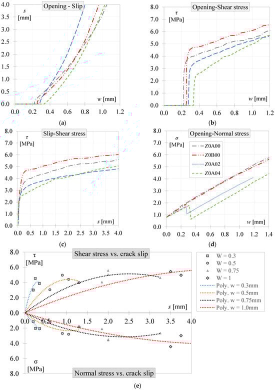
Figure 7.
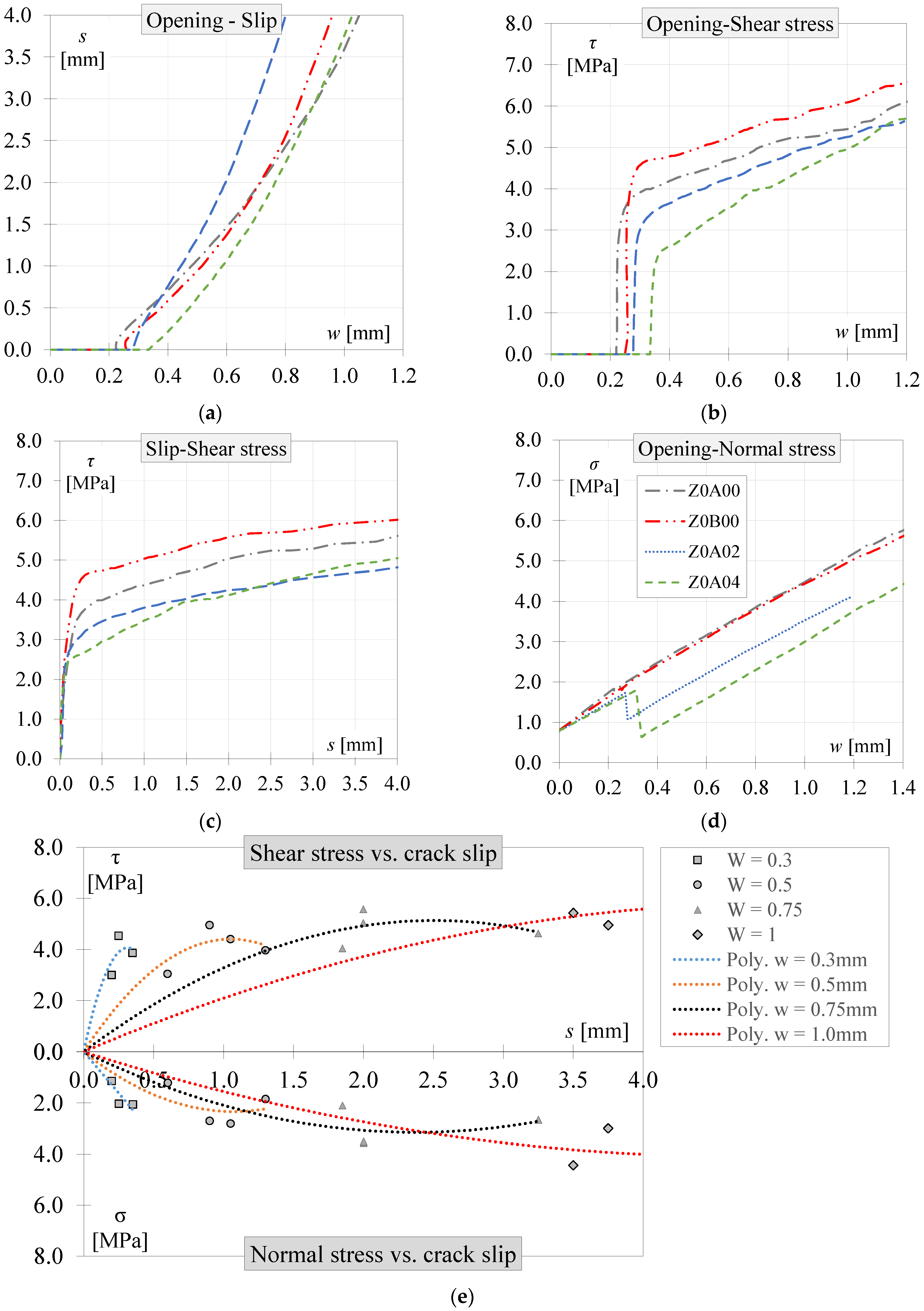
PC push-off experimental results: (a) crack opening vs. crack slip, (b) crack opening vs. shear stress, (c) slip displacement vs. shear stress, (d) crack opening vs. normal stress, and (e) interaction diagram.
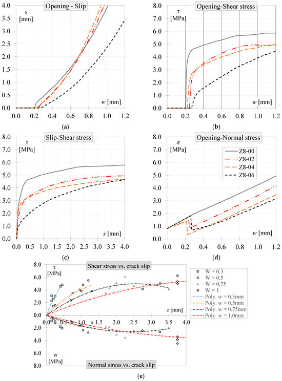
Figure 8.
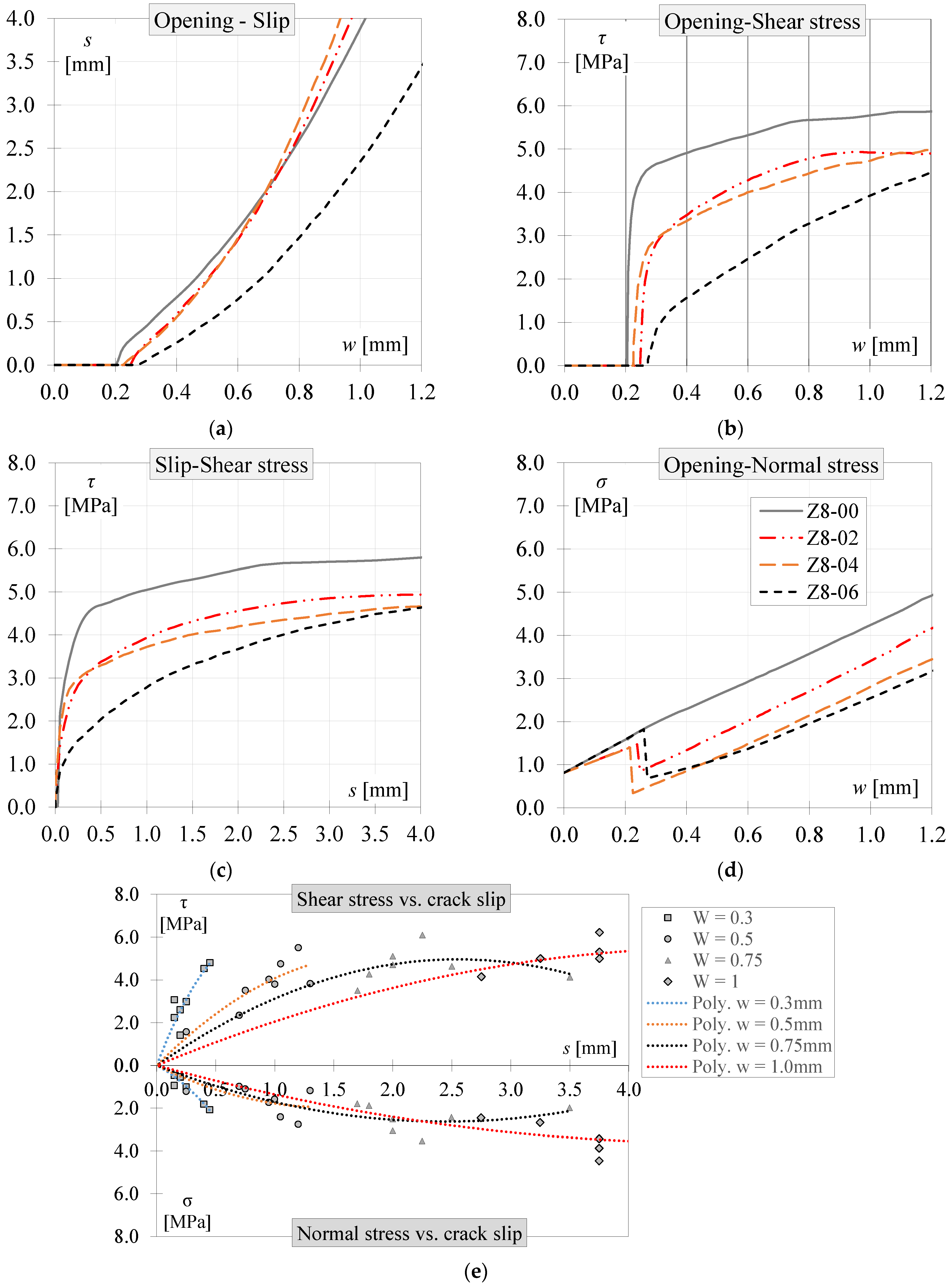
PFRC8 push-off experimental results: (a) crack opening vs. crack slip, (b) crack opening vs. shear stress, (c) slip displacement vs. shear stress, (d) crack opening vs. normal stress, and (e) interaction diagram.
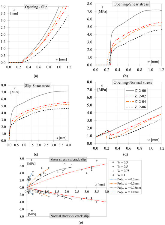
Figure 9.
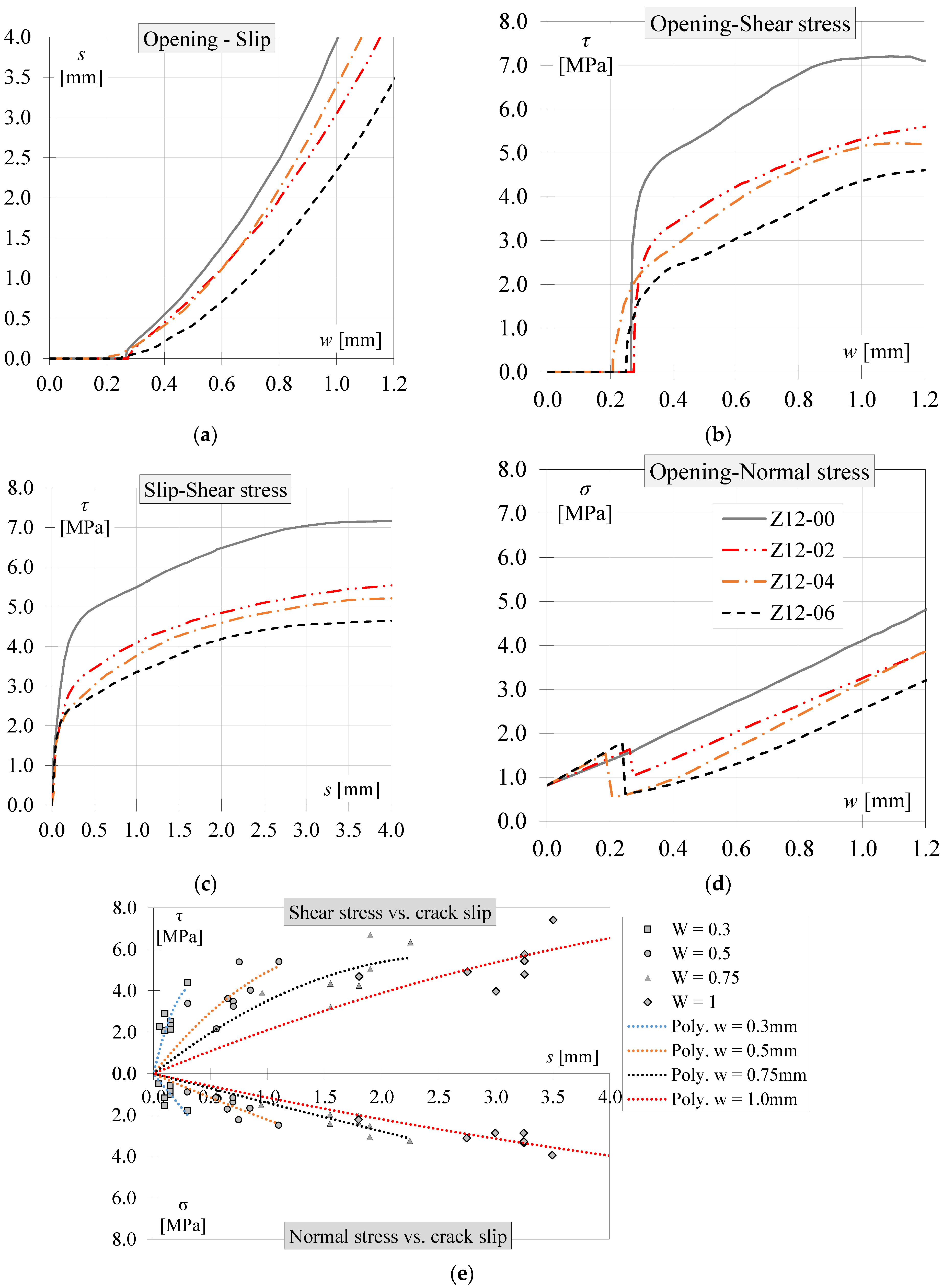
PFRC12 push-off experimental results: (a) crack opening vs. crack slip, (b) crack opening vs. shear stress, (c) slip displacement vs. shear stress, (d) crack opening vs. normal stress, and (e) interaction diagram.
3.1. Plain Concrete Push-Off Results
Figure 7a demonstrates that the PC specimens exhibited similar crack kinematic behaviour, despite having different initial crack openings (w0). The transfer of shear in the specimens (Figure 7a,c) displayed greater stiffness at the beginning of the push-off tests. However, the stiffness decreased after approximately 0.25 mm of slip displacement. Notably, while the shear stiffness reduced in all specimens, the shear stress continued to increase with a consistent slope. This behaviour can be attributed to the influence of the crack plane confinement, where both aggregate interlocking and crack roughness were influenced by the external confinement.
Regarding normal stress behaviour (Figure 7d), it is observed that the normal stresses exhibited a similar slope rate among all specimens, representing the axial stiffness of the external steel frame.
To facilitate a comparison between τ, σ, w, and s, the obtained results are presented in Figure 7e using trend lines based on constant crack opening values. The points corresponding to the same crack openings (0.3, 0.5, 0.75, and 1.0 mm) were identified from all test results obtained for the four PC specimens and plotted on a coordinate plane. In other words, from each push-off test, values of slip, normal stress, and shear stress were obtained at crack openings of 0.3, 0.5, 0.75, and 1 mm. These data were used to plot the points, and polynomial trend lines were fitted to each data point. As depicted in Figure 7e, the shear and normal stresses transferred in PC cracks increased with crack opening and slip displacement. With large crack openings (w = 0.75 and 1 mm), the normal and shear stresses exhibited similar magnitudes, while shear stress was approximately twice the normal stress for small crack openings.
3.2. PFRC Push-Off Results
The crack kinematic behaviour in the PFRC elements was analysed using 16 pre-cracked push-off specimens. Two specimens were tested for each concrete type (PFRC8 and PFRC12) and for each considered W (0.0, 0.2, 0.4, and 0.6 mm). The average results for two specimens with the same W are presented in Figure 8 and Figure 9.
In the case of PFRC8 and PFRC12, the shear stresses transferred (as shown in Figure 8c and Figure 9c) exhibited higher stiffness at the beginning of the push-off test. Similarly to the PC results, the PFRC elements with larger initial crack widths (w0) transferred less shear stress, such as elements Z8-06 and Z12-06. Conversely, the elements with zero crack width (W) transferred more shear stress, namely elements Z8-00 and Z12-00, which had lower w0. As the slip displacement reached approximately 0.25 mm, the shear stiffness decreased, but the shear stress continued to increase at a consistent rate across all specimens due to the confinement provided by the external frame. Figure 8d and Figure 9d depict the transfer of normal stresses in the crack with similar stiffness among all specimen types and PFRC variants, as observed in the PC specimens. This behaviour can be attributed to the confinement effect induced by the external frame, which remained constant throughout the experimental procedure for all specimens. Finally, the influence of initial confinement on shear stresses is evident in Figure 8b and Figure 9b, where specimens with higher σ0 exhibited higher transferred shear stress.
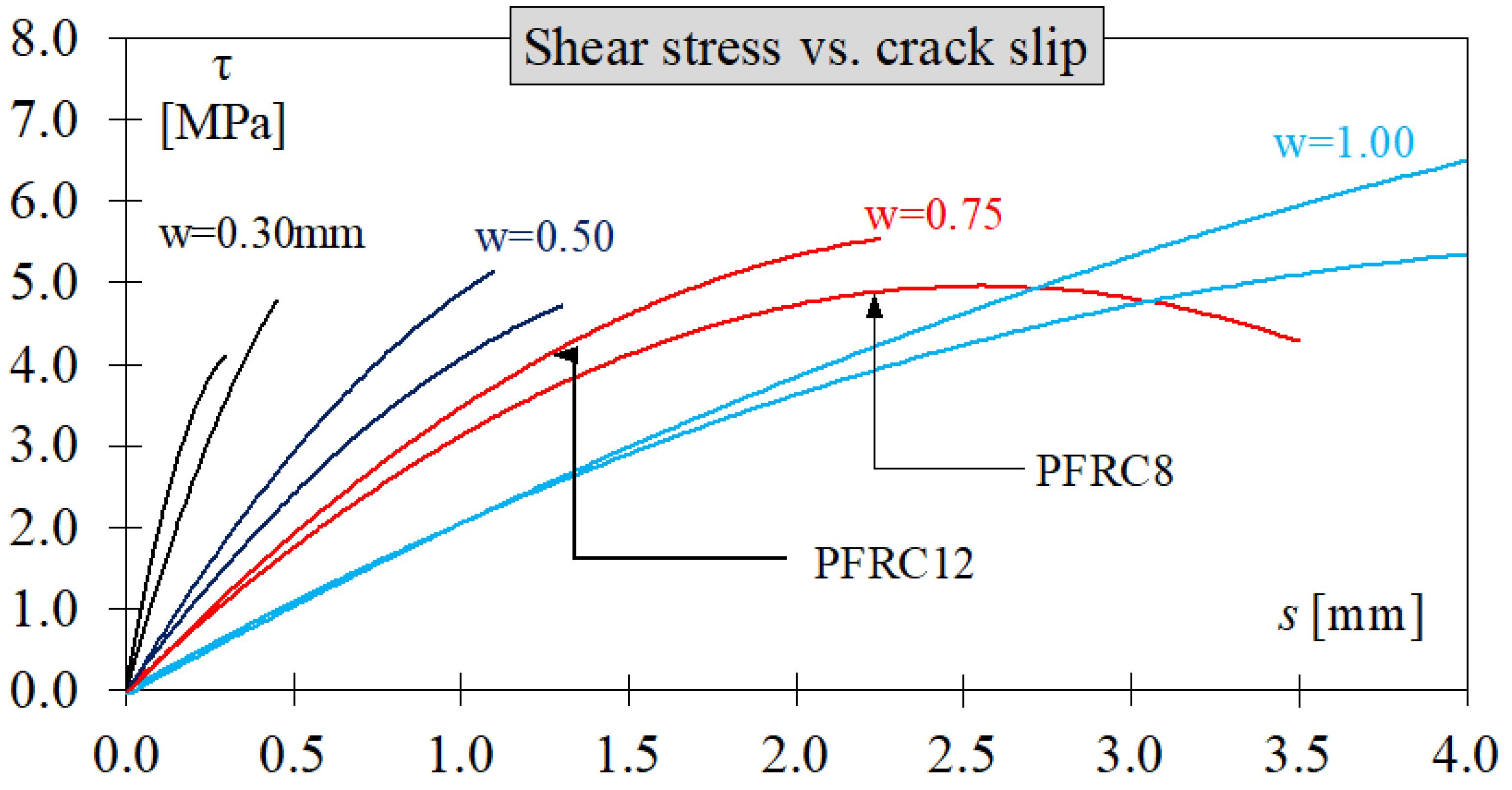
To observe the interaction between shear stress, normal stress, crack opening, and slip displacements among the tested specimens, trend lines were plotted, as shown in Figure 8e and Figure 9e for PFRC8 and PFRC12, respectively. These trend lines were fitted using data points corresponding to the same crack opening (0.3, 0.5, 0.75, and 1.0 mm) for each concrete type. Linear or polynomial trend lines were chosen to achieve a better fit.
As shown in Figure 8e and Figure 9e, the transferred shear and normal stresses decreased as the crack opening and slip displacement increased. It can be observed that the data points align more closely with the trend lines at smaller crack openings (0.3 and 0.5 mm) compared to larger ones. This effect could be attributed to the variability in fibres bridging the crack plane.
It should be noted that, as no previous studies have reported the use of pre-cracked push-off specimens to evaluate synthetic fibres, the present results cannot be directly compared with the existing literature. Nevertheless, the crack kinematics (slip–opening) and the shear–slip response exhibit similarities to those reported by Araújo et al. [34], who investigated pre-cracked push-off specimens reinforced with steel fibres. Regarding the normal stress behaviour, methodological differences are evident: in the referenced study, the normal force was applied through bars embedded within the concrete, whereas in the present study, an external rigid frame was employed. This distinction significantly affects the response, as the embedded bars likely underwent plastic deformation, resulting in a non-linear behaviour. In contrast, in the present study, the frame bars possess a sufficient cross-section, ensuring that they remain within the elastic range throughout the test.
3.3. Effect of Fibre Content on Shear Behaviour
Table 4 provides a summary of the test results for specimens at slip displacements of 0.5, 1.5, 2.5, and 3.5 mm, aiming to determine the influence of fibre content on shear behaviour. Comparing the shear stresses between PC and PFRC8, an increase from 0.05 to 0.32 MPa in PFRC8 and from 0.61 to 1.46 MPa in PFRC12 was observed. When comparing the shear stress increments between PFRC8 and PFRC12, the values ranged from 0.08 to 1.41 MPa, depending on the crack slip and W. It is important to note that each specimen type had specific initial conditions (w0 and σ0) which influenced its shear behaviour, as depicted in Figure 8 and Figure 9. Therefore, the increments presented in Table 4 should be considered within this context.
Table 4.
A comparison of the shear test results (CV in brackets).
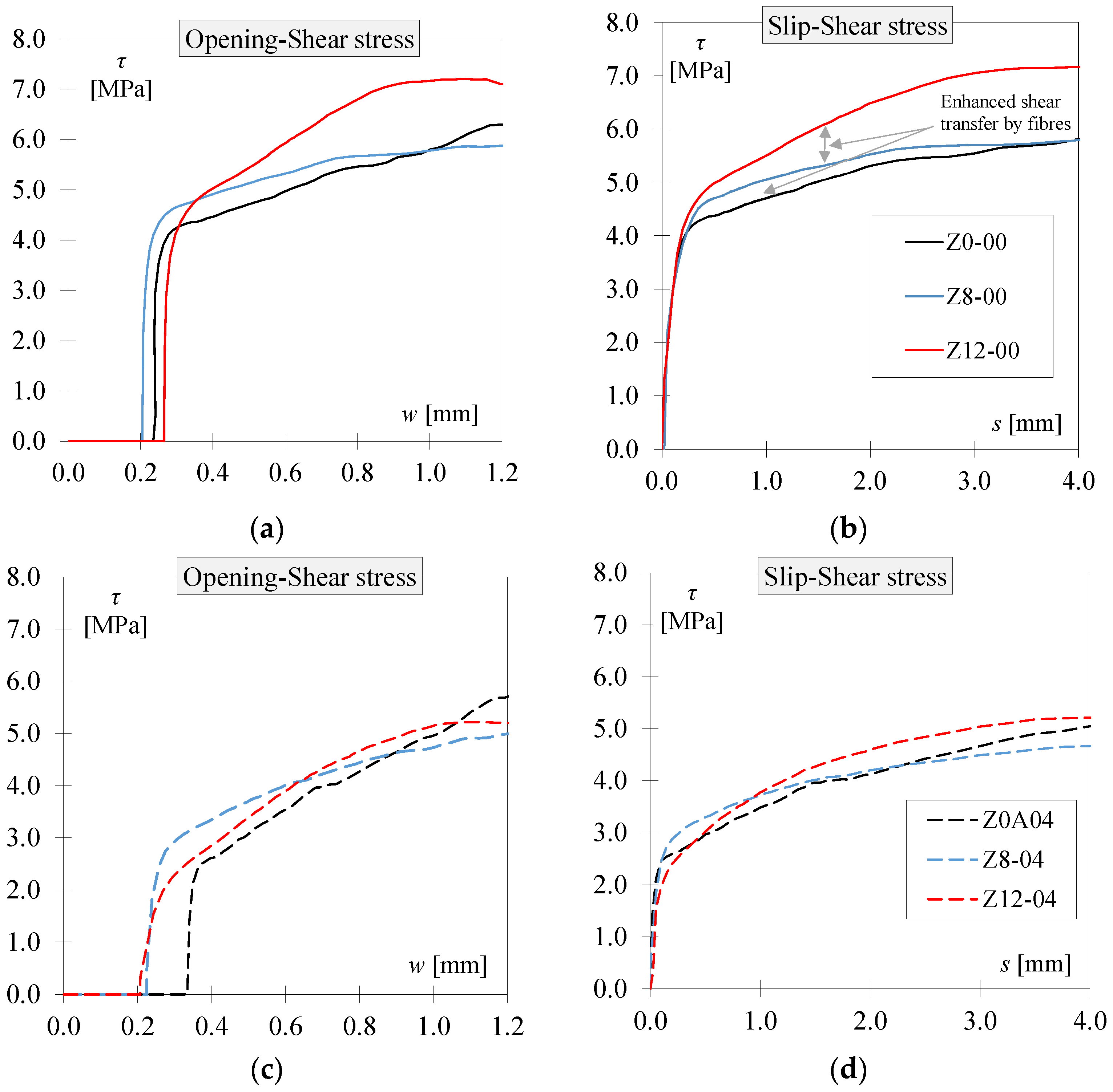
The influence of fibres on shear behaviour, as well as the variations caused by the initial conditions, can be clearly observed in Figure 10, which compares specimens of each concrete type with the same W values (0.0 and 0.4 mm). When comparing the concretes with W = 0.0 mm, it is evident that different initial crack openings close to 0.2 mm were obtained. The addition of 8 and 12 kg/m3 of fibres resulted in an increase in shear stress. Similarly, when comparing the test results at W = 0.4 mm, a significant difference in initial crack openings among the three specimens can be observed.
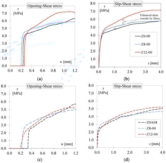
Figure 10.
Comparison between PC results and PFRC8 and PFRC12: (a) shear stress vs. crack opening (W = 0 mm), (b) shear stress vs. slip displacement (W = 0 mm), (c) shear stress vs. crack opening (W = 0.4 mm), (d) shear stress vs. slip displacement (W = 0.4 mm).
It can also be observed in both Figure 10b,d that the contribution of the fibres is significantly greater when comparing the PC specimens with PFRC12, for both low (less than 1 mm) and high (4 mm) slip values. This effect can also be observed by comparing the shear stress–slip relationships at given crack openings between the two PFRC specimens, using the trend lines shown in Figure 11. Shear stress increased with the increment in fibre content from 8 to 12 kg/m3. This increment was more evident for large slip displacements than for small slip displacements.

Figure 11.
Comparison of shear stress versus slip displacement trend lines for PFRC8 and PFRC12.
3.4. Effect of Initial Confinement on Specimens’ Shear Behaviour
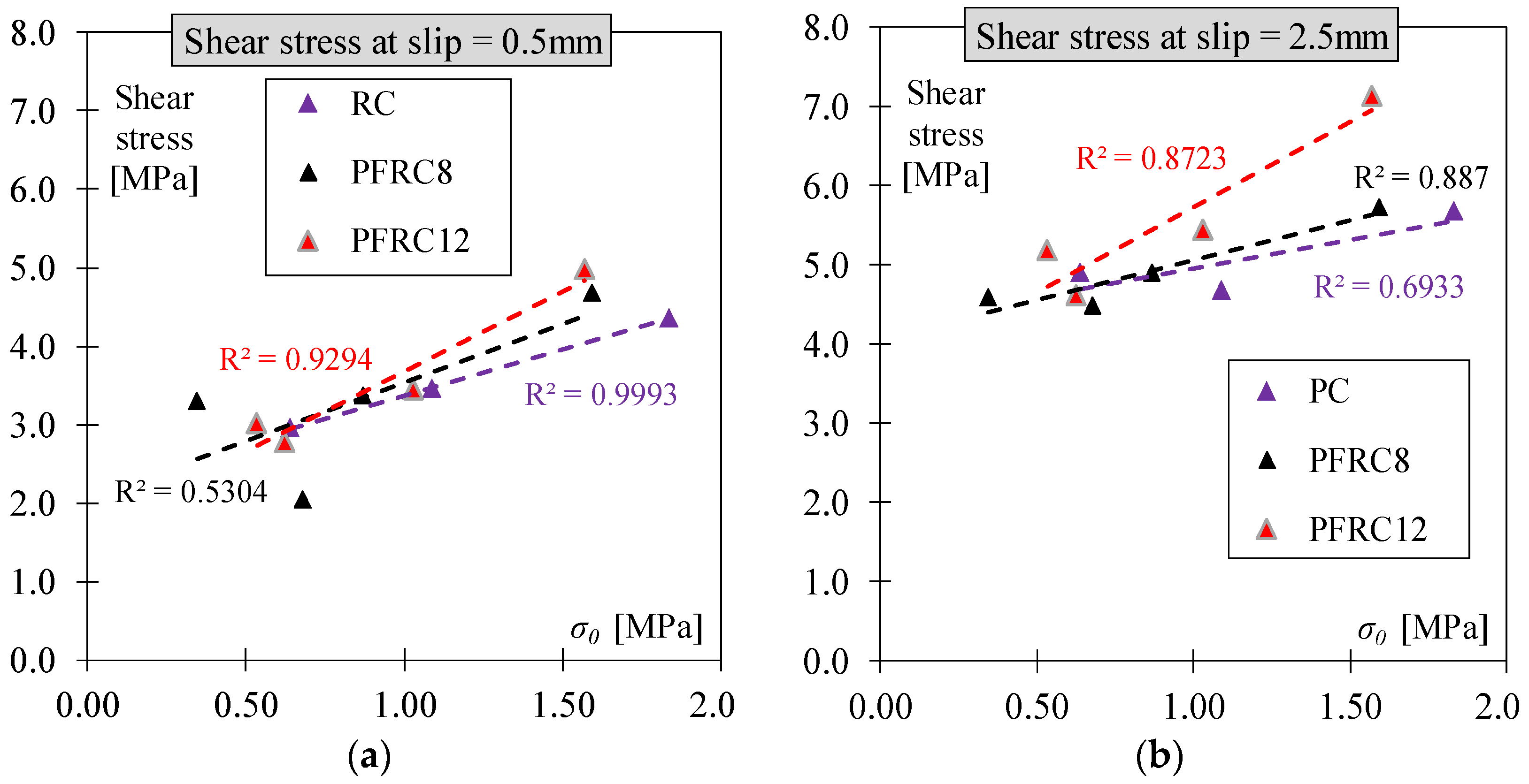
Table 5 provides the shear results at slip displacements of 0.5 and 2.0 mm, along with their corresponding W, σ0, and w0 values. Figure 12 demonstrates the influence of existing confinement (σ0) on the shear behaviour of specimens at different slip displacements (0.5 and 2.0 mm). The level of confinement strongly affected the shear behaviour in all three types of concrete. As depicted in Figure 12a, when the confinement was higher, the shear stress obtained was also higher. This trend was consistently observed in all three concrete types. Additionally, Figure 12b illustrates the same trend when the slip displacement reached 2.5 mm.
Table 5.
Shear stress results and corresponding confinement.
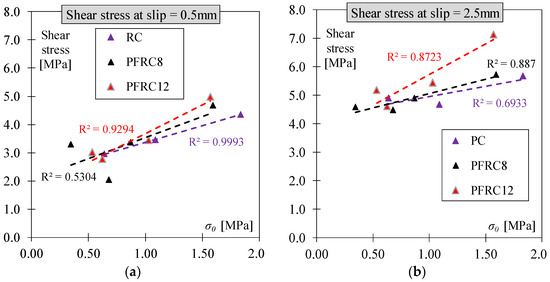
Figure 12.
Relationship between confinement and shear stress at slip = 0.5 (a) and 2.5 (b) mm.
4. Concluding Remarks
In this experimental study, the effect of fibre content, specimen confinement, and initial crack opening on shear transfer in polypropylene fibre-reinforced concrete was investigated. Twenty pre-cracked push-off specimens were investigated, including both PC and PFRC specimens, which were subsequently tested under direct shear. Two different fibre contents, 8 kg/m3 and 12 kg/m3, were studied. The initial conditions were characterised by the initial crack gap (W = 0.0, 0.2, 0.4, and 0.6 mm).
Based on the experimental results obtained in this study, the following conclusions can be drawn:
- Increasing the fibre content from 8 kg/m3 to 12 kg/m3 resulted in an increase in both post-cracking flexural and shear strength. However, the increment in shear strength was not significant when the fibre content varied from 0 to 8 kg/m3, as observed throughout the entire range of fibre content studied (from 0 to 12 kg/m3).
- The results of this study demonstrate that the magnitude of crack opening prior to the push-off test had a significant influence on stress transmission. Specifically, it was observed that larger crack openings resulted in reduced shear and normal stresses.
- Increasing the fibre dosage from 8 kg/m3 to 12 kg/m3 led to a rise in both normal and shear stresses, reaching up to 1.0 MPa. This increment was primarily influenced by crack opening and crack slip displacement. Notably, larger crack openings and slip displacements highlighted the significant role of fibres in effectively transferring stresses, surpassing the contributions of other shear transfer mechanisms.
- The obtained experimental results show a pattern of correlation between slip displacement, crack opening, confinement level, and the shear stress of the concrete specimens. In fact, higher levels of initial confinement led to an increased value of shear stress in small and large slip displacements. An R-squared value of 0.82 was obtained on average for the relationship between initial confinement and shear stress.
Author Contributions
Conceptualization, J.N.-G. and P.S.; methodology, J.N.-G. and F.O.-N.; investigation, F.O.-N.; resources, J.N.-G. and P.S.; data curation, F.O.-N.; writing—original draft preparation, J.N.-G. and F.O.-N.; writing—review and editing, J.N.-G. and P.S.; funding acquisition, J.N.-G. All authors have read and agreed to the published version of the manuscript.
Funding
This work is part of the project “CIAICO/2022/045” and has received support from the “Conselleria de Innovación, Universidades, Ciencia y Sociedad Digital, Generalitat Valenciana (ES)”.
Data Availability Statement
The data presented in this study are contained within the article.
Conflicts of Interest
The authors declare no conflict of interest.
References
- Di Prisco, M.; Plizzari, G.; Vandewalle, L. MC2010: Overview on the Shear Provisions for FRC. In Proceedings of the Workshop, Salo, Lake Garda, Italy, 15–16 October 2010; pp. 61–76. [Google Scholar]
- Kim, K.S.; Lee, D.H.; Hwang, J.H.; Kuchma, D.A. Shear Behavior Model for Steel Fiber-Reinforced Concrete Members without Transverse Reinforcements. Compos. Part B Eng. 2012, 43, 2324–2334. [Google Scholar] [CrossRef]
- Bencardino, F.; Rizzuti, L.; Spadea, G.; Swamy, R.N. Experimental Evaluation of Fiber Reinforced Concrete Fracture Properties. Compos. Part B Eng. 2010, 41, 17–24. [Google Scholar] [CrossRef]
- Marar, K.; Eren, Ö.; Roughani, H. The Influence of Amount and Aspect Ratio of Fibers on Shear Behaviour of Steel Fiber Reinforced Concrete. KSCE J. Civ. Eng. 2017, 21, 1393–1399. [Google Scholar] [CrossRef]
- Sahoo, D.R.; Bhagat, S.; Reddy, T.C.V. Experimental Study on Shear-Span to Effective-Depth Ratio of Steel Fiber Reinforced Concrete T-Beams. Mater. Struct. 2016, 49, 3815–3830. [Google Scholar] [CrossRef]
- Ortiz Navas, F.; Navarro-Gregori, J.; Leiva Herdocia, G.; Serna, P.; Cuenca, E. An Experimental Study on the Shear Behaviour of Reinforced Concrete Beams with Macro-Synthetic Fibres. Constr. Build. Mater. 2018, 169, 888–899. [Google Scholar] [CrossRef]
- Lakavath, C.; Suriya Prakash, S.; Dirar, S. Experimental and Numerical Studies on Shear Behaviour of Macro-Synthetic Fibre Reinforced Prestressed Concrete Beams. Constr. Build. Mater. 2021, 291, 123313. [Google Scholar] [CrossRef]
- Lee, G.; Foster, S. Modelling of Shear-Fracture of Fibre-Reinforced Concrete for the Future. In Tailor Made Concrete Structures: New Solutions for Our Society: Proceedings of the International FIB Symposium 2008, Amsterdam, The Netherlands, 19–21 May 2008; Walraven, J.C., Stoelhorst, D.E., Eds.; CRC Press: Boca Raton, FL, USA, 2008; pp. 493–499. [Google Scholar]
- Walraven, J.C. Aggregate Interlock: A Theoretical and Experimental Analysis; Delft University: Delft, The Netherlands, 1980. [Google Scholar]
- Gambarova, P.G.; Karakoc, C. A New Approach to the Analysis of the Confinement Role in Regularly Cracked Concrete Elements; North-Holland: Amsterdam, The Netherlands, 1983; Volume 15, ISBN 0444 86701 5. [Google Scholar]
- Vecchio, F.J.; Collins, M.P. The Modified Compression-Field Theory for Reinforced Concrete Elements Subjected to Shear. ACI J. Proc. 1986, 83, 219–231. [Google Scholar] [CrossRef]
- de Lock, V. Influence of Steel Fibres on the Shear Transfer in Cracks. In Proceedings of the International Symposium on Fibre Reinforced Concrete, Madras, India, 16–19 December 1987; pp. 1101–1112. [Google Scholar]
- Balaguru, P.; Dipsia, M.G. Properties of Fiber Reinforced High-Strength Semi-Lightweight Concrete. ACI Mater. J. 1993, 90, 399–405. [Google Scholar] [CrossRef]
- Barragán, B.; Gettu, R.; Agulló, L.; Zerbino, R. Shear Failure of Steel Fiber-Reinforced Concrete Based on Push-off Tests. ACI Mater. J. 2006, 103, 251–257. [Google Scholar]
- Echegaray-Oviedo, J. Upgrading the Push off Test to Analyze the Contribution of Steel Fiber on Shear Transfer Mechanisms. Ph.D. Thesis, Universitat Politècnica de València, Valencia, Spain, 2014. [Google Scholar]
- Cuenca, E.; Serna, P. Shear Behavior of Self-Compacting Concrete and Fiber-Reinforced Concrete Push-Off Specimens. In Design, Production and Placement of Self-Consolidating Concrete; RILEM Bookseries; Springer: Dordrecht, The Netherlands, 2010; Volume 1, pp. 429–438. [Google Scholar]
- Picazo, A.; Gálvez, J.C.; Alberti, M.G.; Enfedaque, A. Assessment of the Shear Behaviour of Polyolefin Fibre Reinforced Concrete and Verification by Means of Digital Image Correlation. Constr. Build. Mater. 2018, 181, 565–578. [Google Scholar] [CrossRef]
- Alberti, M.; Picazo, A.; Enfedaque, A.; Gálvez, J.C. Shear Behaviour of Polyolefin and Steel Fibre-Reinforced Concrete. In Proceedings of the 10th International Conference on Fracture Mechanics of Concrete and Concrete Structures, Bayonne, France, 23–26 June 2019. [Google Scholar] [CrossRef]
- EN 14651; Test Method for Metallic Fibres Concrete. Measuring the Flexural Tensile Strength. European Committee for Standardization: Brussels, Belgium, 2005.
- Majdzadeh, F.; Soleimani, S.M.; Banthia, N. Shear Strength of Reinforced Concrete Beams with a Fiber Concrete Matrix. Can. J. Civ. Eng. 2006, 33, 726–734. [Google Scholar] [CrossRef]
- Japan Society of Civil Engineers. JSCE-SF6, Method of Test for Shear Strength of Steel Fiber Reinforced Concrete (SFRC); 536 Japan Society of Civil Engineers: Tokyo, Japan, 1990; pp. 67–69. [Google Scholar]
- Mostafazadeh, M.; Abolmaali, A. Shear Behavior of Synthetic Fiber Reinforced Concrete. Adv. Civ. Eng. Mater. 2016, 5, 371–386. [Google Scholar] [CrossRef]
- Mostafazadeh, M.; Abolmaali, A.; Ghahremannejad, M. Shear Strength of Synthetic Fiber-Reinforced Concrete Box Culverts. J. Bridg. Eng. 2019, 24, 1–13. [Google Scholar] [CrossRef]
- Charron, J.P.; Desmettre, C.; Androuët, C. Flexural and Shear Behaviors of Steel and Synthetic Fiber Reinforced Concretes under Quasi-Static and Pseudo-Dynamic Loadings. Constr. Build. Mater. 2020, 238, 117659. [Google Scholar] [CrossRef]
- Federation Internationale de La Precontrainte (FIP). Shear at the Interface of Precast and In Situ Concrete; FIP: Lausanne, Switzerland, 1978. [Google Scholar]
- Khanlou, A.; Macrae, G.A.; Scott, A.N.; Hicks, S.J.; Clifton, G.C. Shear Performance of Steel Fibre-Reinforced Concrete. Australas. Struct. Eng. Conf. 2012, 1, 8. [Google Scholar]
- Susetyo, J.; Gauvreau, P.; Vecchio, F.J. Effectiveness of Steel Fiber as Minimum Shear Reinforcement. ACI Struct. J. 2012, 109, 426–428. [Google Scholar]
- Lee, S.; Cho, J.; Vecchio, F.J. Analysis of Steel Fiber-Reinforced Concrete Elements Subjected to Shear. ACI Struct. J. 2016, 113, 275–286. [Google Scholar] [CrossRef]
- Lee, S.; Cho, J.; Vecchio, F.J. Diverse Embedment Model for Steel Fiber-Reinforced Concrete in Tension: Model Development. ACI Mater. J. 2011, 108, 516. [Google Scholar]
- Lee, S.; Cho, J.; Vecchio, F.J. Simplified Diverse Embedment Model for Steel Fiber- Reinforced Concrete Elements in Tension. ACI Mater. J. 2014, 110, 403–412. [Google Scholar]
- Gehri, N.; Mata-Falcón, J.; Kaufmann, W. Experimental Investigation of the Shear Response of Large-Scale Fibre-Reinforced Concrete Panels. Eng. Struct. 2023, 295, 116598. [Google Scholar] [CrossRef]
- Gaston, J.P.B. Shear Behavior of Macro-Synthetic Fiber-Reinforced Concrete Panels. Master’s Thesis, University of Washington, Seattle, WA, USA, 2023. [Google Scholar]
- EN 12390-3; Testing Hardened Concrete. Part 3: Compressive Strenght of Test Specimens. European Committee for Standardization: Brussels, Belgium, 2009.
- Araújo, D.d.L.; Lobo, F.A.; Martins, B.G. A Shear Stress-Slip Relationship in Steel Fibre-Reinforced Concrete Obtained from Push-off Testing. Constr. Build. Mater. 2021, 293, 123435. [Google Scholar] [CrossRef]
Disclaimer/Publisher’s Note: The statements, opinions and data contained in all publications are solely those of the individual author(s) and contributor(s) and not of MDPI and/or the editor(s). MDPI and/or the editor(s) disclaim responsibility for any injury to people or property resulting from any ideas, methods, instructions or products referred to in the content. |
© 2025 by the authors. Licensee MDPI, Basel, Switzerland. This article is an open access article distributed under the terms and conditions of the Creative Commons Attribution (CC BY) license (https://creativecommons.org/licenses/by/4.0/).