Article

Tension Lap Splices in Recycled-Aggregate Concrete Strengthened with Steel–Polyolefin Fibers

Department of Civil Engineering, University of Basrah, Basra 61004, Iraq
*
Author to whom correspondence should be addressed.
Fibers 2024, 12(8), 60; https://doi.org/10.3390/fib12080060
Submission received: 14 June 2024 / Revised: 10 July 2024 / Accepted: 17 July 2024 / Published: 24 July 2024

Abstract

:
The bond strength of tension lap splices in recycled-coarse-aggregate-reinforced concrete strengthened with hybrid (steel–polyolefin) fibers was experimentally investigated. This study was conducted with the help of twelve lap-spliced beam specimens. The replacement level of coarse natural aggregates with recycled concrete aggregate (RCA) was 100%. The following variables were investigated: various ranges of steel–polyolefin fibers—100–0%, 75–25%, 50–50%, 25–75%, and 0–100%—in which the total volume fraction of fibers ( V f ) remains constant at 1%; and two lengths of lap splices for rebars of 16 mm diameter ( d b ): 10 d b and 15 d b . The test results showed that the best range of steel–polyolefin fibers that gave the highest bond strength was 50–50%. The ductility of the fiber-reinforced recycled-aggregate (FR-RA) concrete was significantly improved for all the cases of various relative ratios of steel and polyolefin fibers. The bond strength was also predicted using three empirical equations proposed by Orangun et al., Darwin et al., and Harajli. This study showed that the Harajli equation gave a more accurate estimation of the bond strength of reinforcing bars embedded in FR-RA concrete than those proposed by Orangun et al. and Darwin et al.

1. Introduction

The production of concrete requires a significant amount of natural resources; about 75% of the concrete volume is occupied by aggregates. The consumption of natural coarse aggregates in concrete production annually requires twenty billion tonnes; however, in the next 2 to 3 decades, this need is expected to rise to about forty billion tonnes [1]. Furthermore, there is an enormous quantity of waste around the globe resulting from the destruction of old structures or the construction of new ones. The anticipated yearly waste generated from these actions is 900 million tons in Europe, the US, and Japan and 200 million tons in China [2,3].
The environmental influence of producing concrete has been reduced in several ways, one of which is using recycled aggregate made from demolition and construction debris rather than natural aggregate. The benefit of using this method is to sustainably eliminate the massive amounts of demolition and construction waste produced around the world and also to reduce the demand for natural aggregate.
The durability and mechanical performance of the concrete could be affected when recycled aggregate is used in the concrete mix [4,5]. However, it has been reported that no influence was observed on the concrete mix when normal concrete was replaced by 20–30% recycled aggregate [1]. When the replacement rate reached 100%, the compressive strength decreased by 12–25% [1,2,3,4,5,6,7], and the tensile strength decreased by 10–24%; the flexural strength decreased to 16–23% [8,9].
The aggregate form has a remarkable effect on the bond behavior between concrete materials and reinforcement. The presence of a soft and porous mortar layer on the particles of the recycled concrete aggregate may cause cracks to spread more easily, and this may lead to lower bond strength.
Various ideas have emerged to enhance the performance and overcome the problems of concrete caused due to the use of recycled aggregate, such as using admixtures [10], treating recycled aggregate [11,12], and adding additional cementitious ingredients and fibers. On the other hand, various types of steel and synthetic fibers were used to enhance the flexural and compressive strength, toughness, deformation, fatigue, ductility, and impact resistance of recycled aggregate [13,14,15,16,17]. Carneiro et al. [14] found that the concrete compressive strength increased by 13% when using 0.75% steel fibers (hooked-end) with a 25% replacement of recycled aggregate. Akça et al. [15] used polypropylene fibers of 1% together with 55% recycled aggregate replacement; they gained an increase of 4% in flexural strength and 31% in tensile strength. Arslan [18] found that the fracture energy of ordinary concrete, which is defined as the required energy to initiate a crack in the concrete, increased by 35% when glass and basalt fibers were used. In a similar manner, adding steel and polypropylene fibers to ordinary concrete could raise the residual flexural–tensile strength [19,20]. Yet, the steel fibers gave results that may be considered more scattered compared with synthetic macro-fibers because of the low number of steel fibers with less homogeneous distribution across the fracture surface [21]. Currently, synthetic fibers could be utilized separately or together with steel fibers in the pavements applied to high-impact loading to minimize shrinkage and enhance impact resistance [21,22]. The effects of steel and polyolefin fiber hybridization on the mechanical properties of the base concrete were investigated by Lee et al. [23]. Two fiber contents (0.54 and 1.08 vol%) with polyolefin fiber proportions varied from 0 to 100% in the hybrid fibers were considered. They showed that using 0.54 vol% fiber hybridization did not clearly affect the mechanical properties of concrete. However, a synergetic effect occurred at 1.08 vol% fiber content.
With the help of a variety of testing techniques including digital image correlation (DIC) techniques [24], acoustic emission (AE) techniques [25], and piezoelectric transducers [26], the damage characteristics of fiber-reinforced concrete (FRC) have been investigated, such as internal crack types, propagation directions, and the regularity of spatiotemporal evolution.
Several studies have been made to investigate the bond behavior of recycled-aggregate concrete. Based on pull-out tests conducted by Ajdukiewicz and Kliszewicz [9], for high-performance concrete made from recycled aggregate, the peak bond stress decreased by 20% compared with natural aggregate concrete. While for concrete in which the replacement was only for natural coarse aggregate with recycled aggregates, the peak bond stress dropped to 8%. According to the pull-out tests conducted by Xiao and Falkner [27] for concrete with and without recycled aggregates, the obtained bond strength values were practically uninfluenced regardless of the proportion of recycled aggregate used in the concrete. They recommended identical anchorage lengths. The pull-out experiments implemented by Choi and Kang [28] demonstrated that the model presented by ACI Committee 408 [29] estimated unconservative bond strength values for recycled-aggregate concrete. Based on their splice beam tests, other researchers [30,31,32] revealed lower bond strength for recycled-aggregate concrete compared to natural-aggregate concrete. Also, Morohashi et al. [33] found that the splitting bond strengths were similar for the natural and recycled aggregates.

Research Significance

Only a few studies have investigated the effect of fibers on the bond performance of reinforcing bars in recycled-aggregate concrete. However, to the best of the author’s knowledge, there has been no study that considered the effect of hybrid fibers (steel and polyolefin) on the bond performance between reinforcing bars and recycled-aggregate concrete (RAC). Therefore, the primary goal of this work was to study the bond behavior of RAC beams having hybrid steel–polyolefin fibers with various ranges (steel–polyolefin: 100–0%, 75–25%, 50–50%, 25–75%, and 0–100%) in which the total volume fraction of fibers ( V f ) remains constant at 1%. The replacement rate of recycled coarse aggregate was 100% in the all-mix design. Two lengths of lap splice for rebars of 16 mm diameter were used: 10 and 15 times the diameter of the rebars.
It was a significant investigation to determine whether the steel and polyolefin fiber hybridization would improve the bond performance of the lap splices, as well as the ductility of the failure mode of FR-RA concrete. The findings of this study would therefore affect the design and construction of structural elements.

2. Experimental Program

This study required testing twelve recycled coarse aggregate RC beams of 1700 mm simple span loaded by a two-point load using various percentages of steel–polyolefin fibers to investigate the behavior of the bond between concrete and reinforcement bars. The beams were molded and tested at the Civil Engineering Department Laboratories, College of Engineering, University of Basrah.

3. Specimens Details

Twelve recycled-aggregate RC beams of dimensions 1800 mm (length), 300 mm (depth), and 180 mm (width) with lap-spliced tension steel bars at the mid-span of the beams were used. The beam specimens were loaded utilizing a four-point-load configuration with 600 mm span between the loadings.
Depending on the lap splice length ( l s ), two groups of beams were used ( l s = 10 and 15 d b ). For both groups, the volume fractions of fibers remained constant ( V f = 1%) with various ratios of steel–polyolefin fibers (steel–polyolefin: 100–0%, 75–25%, 50–50%, 25–75%, and 0–100%).
Two bars of 16 mm diameter were used as longitudinal tension reinforcement, spliced at mid-span with lengths ( l s = 160 mm and 240 mm) for each beam specimen. The lap splice lengths of 10 db and 15 db, both considerably less than the required development length by ACI 318-19 [34], were selected to develop local bond failure conditions. The tension reinforcement was configured in such a manner that the covers of concrete in all directions became almost identical. Two bars of 10 mm diameter were placed at the compression zone to support the shear reinforcement. For all beams, bars of 10 mm diameter were provided as transverse reinforcement outside the splice zone with 100 mm spacing. Beam reinforcement details corresponding to lap splice lengths of 160 mm and 240 mm are shown in Figure 1 and Figure 2, respectively. A typical reinforcement of the lap-spliced beam specimen is shown in Figure 3.
The beam notations and details are listed in Table 1. A notation form consisting of three parts was used. Splice length is mentioned first by 10 and 15 d b , while the second part corresponds to the steel fiber (S) rate, which is 100, 75, 50, 25, and 0%, and the last part is for the polyolefin (P) rate, which is varied as 0, 25, 50, 75, and 100%.

4. Materials

4.1. Steel Reinforcement (Rebar)

The rebar of Grade 60 was used for the main and transverse (shear) reinforcement. Table 2 summarizes average values of yield ( f y ) and ultimate ( f u ) strengths and the observed elongation for used rebar samples. During beam tests, most of the spliced bars did not yield because of the small splice length.

4.2. Fibers

Two types of fibers (hooked-end steel and macro-polyolefin fibers) were considered in this study. There are different shapes of steel fibers available such as straight, hooked, and corrugated fibers; however, the hooked-end steel fibers were used in this study because previous studies have demonstrated that hooked-end steel fibers significantly improve bond properties compared to straight fibers [35]. The used fibers are shown in Figure 4. Their properties are summarized in Table 3.

4.3. Concrete

In this work, the concrete mixes were designed to achieve a 28-day compressive strength of 30 MPa for the cylinder. The concrete ingredients consisted of potable water, recycled concrete aggregates (RCAs), ordinary Portland cement type I, sand, macro-polyolefin and/or steel fibers, and superplasticizer, see Table 4. The physical and chemical properties are shown in Table 5 and Table 6, respectively.
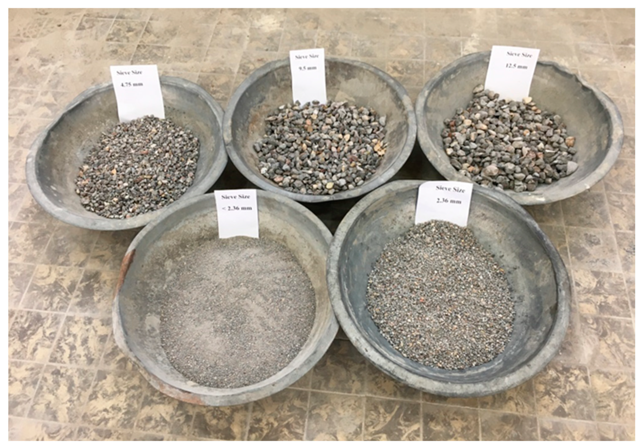
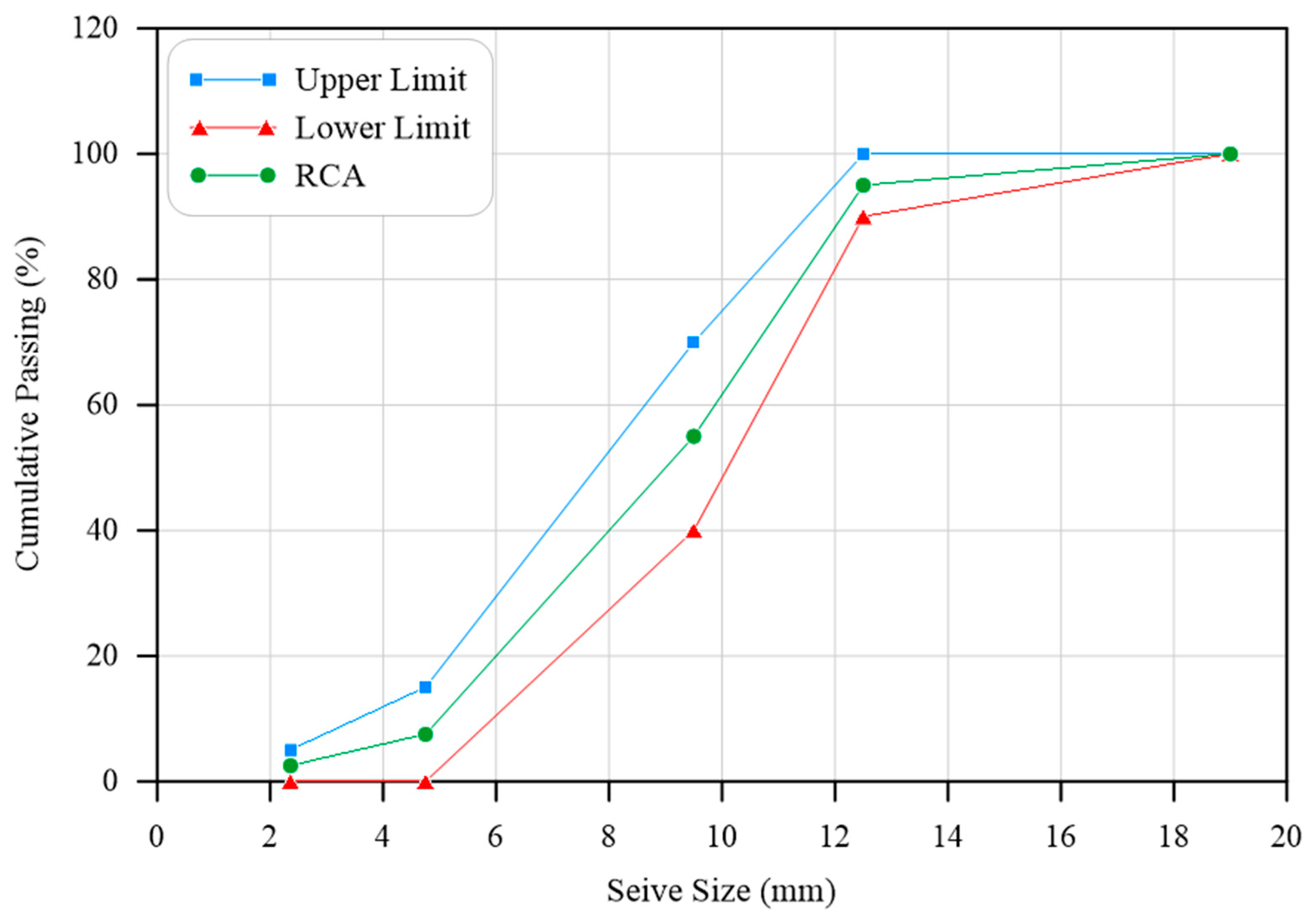
The recycled coarse aggregates were produced from the tested concrete cubes available in the Construction Material Laboratory, Civil Engineering Department, University of Basrah. A waste concrete jaw crusher was used to obtain the required amount of RCA. RCA with a particle size range of 12.5–4.75 mm was used. The grading of coarse RCA was determined in accordance with ASTM C33–18 [36]. The passing percentage of each particle size was selected as the average of the lower and upper passing limits of that particle size. The used particle sizes of coarse RCA and its grading are shown in Figure 5 and Figure 6, respectively. The replacement degree of the RCA is defined as the RCA weight to the coarse aggregates’ total weight used in the concrete. In this work, the replacement rate was 100%.
One of the disadvantages of recycled aggregate is the high absorption of water; therefore, the saturated dry surface was used by pre-soaking the recycled aggregate quantity one day before the specimens were cast. When the soaking time was through, the recycled aggregate was placed on the lab’s clean floor, and any water that had become attached to the aggregate was removed using a soft cloth.
Then, by mixing the dry constituents of the concrete, the polyolefin and/or steel fibers were spread by hand. The ingredients were mixed using a mixture machine to gain a dry homogeneous mix and to avoid the fiber balling in one location. Finally, the superplasticizer with the potable water was added to the mixture machine.
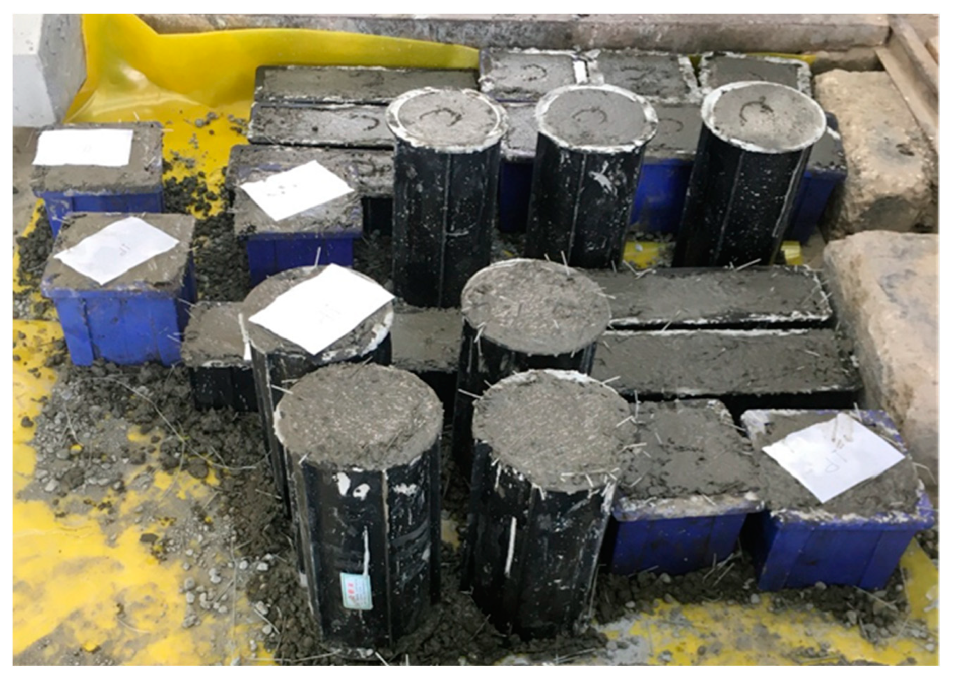
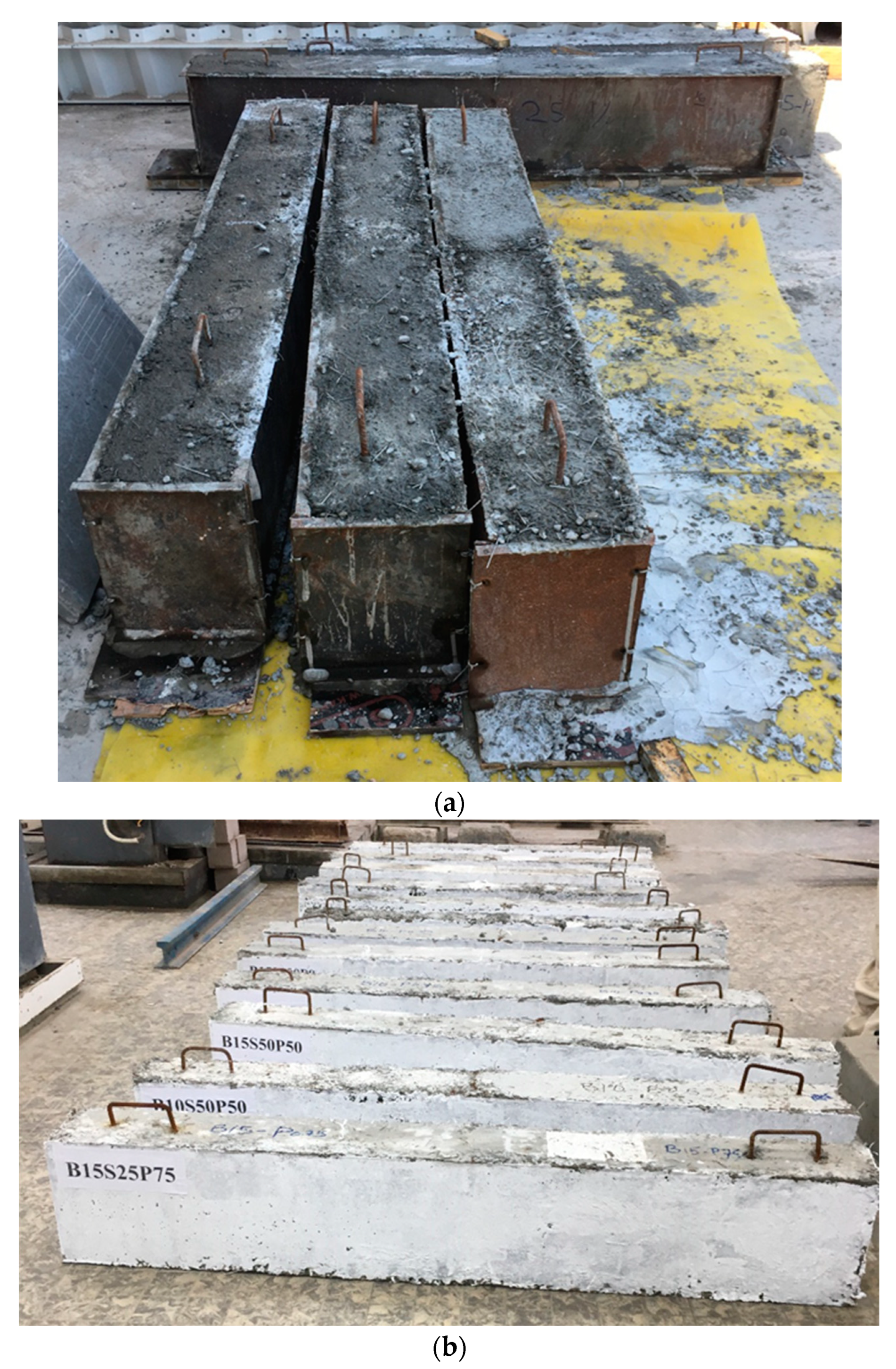
Before the beam specimens were cast, the molds were oiled to prevent the concrete from sticking to the sides. Cube samples with 150 × 150 × 150 mm, cylindrical samples with 150 × 300 mm and prismatic beam samples with 100 × 100 × 350 mm were taken for each mix to determine the compressive strength, the splitting tensile strength, and the flexural strength. The samples are shown in Figure 7, and the test results are shown in Table 7. The average strength values of the specimens in Table 7 are for three specimens at least. The cast beams were cured with water after they were demolded for 28 days, see Figure 8.
The experimental results of cube, cylindrical, and prismatic beam samples showed that the specimens with no fibers under compression experienced a sudden explosion and brittle failure. The fibers had little effect on the compressive strength of fiber-reinforced concrete (FRC). The failure mode, however, changed significantly from brittle to ductile. As a result of the fibers’ bridging effect, the cubic specimens did not crush but maintained their integrity throughout the test. The fibers had more effect on the tensile and flexural strength of FRC. Adding fibers to concrete significantly increased its energy absorption capacity, increased its ductility and resistance to crack growth, and increased its tensile and flexural strength.

5. Test Setup

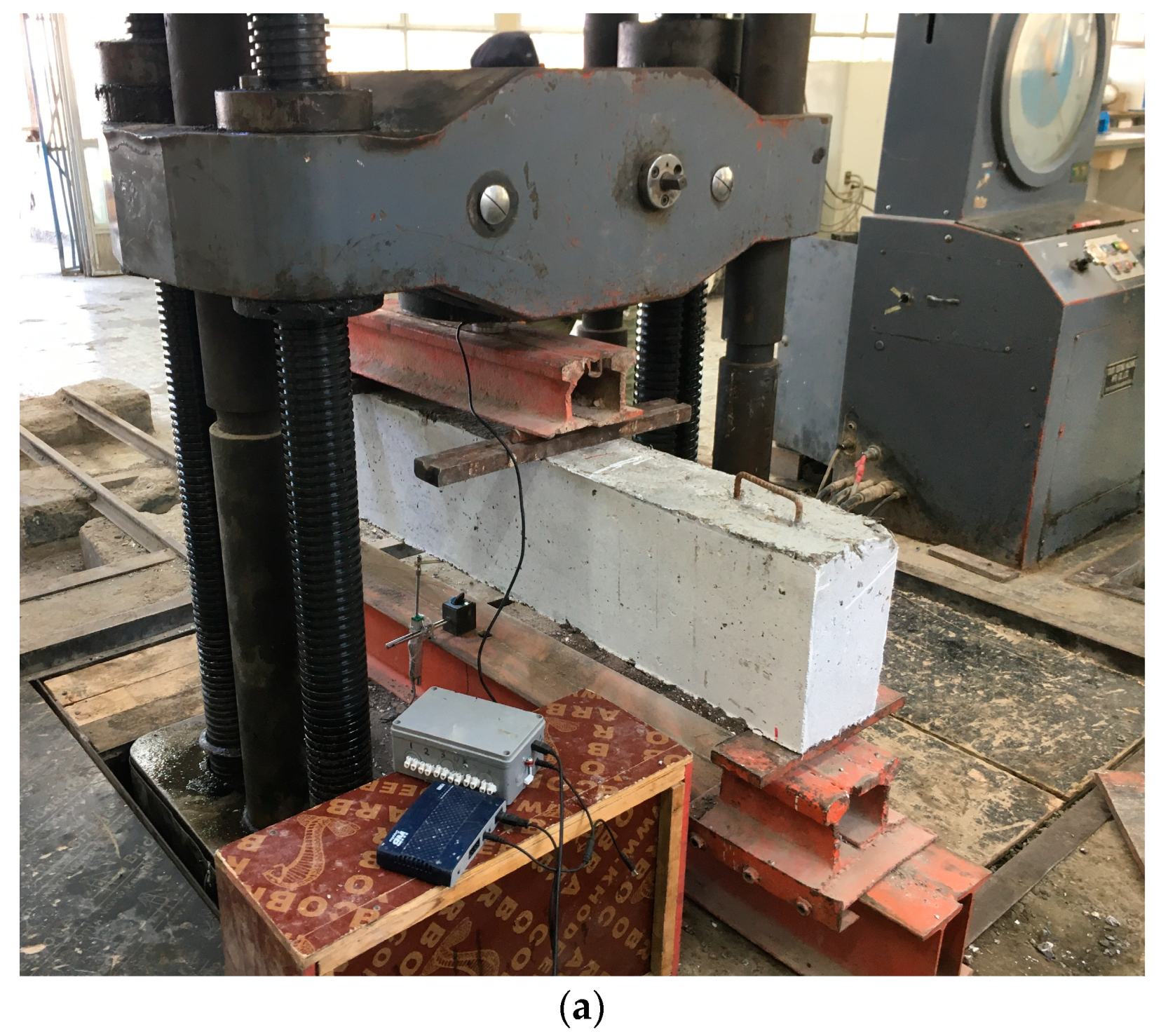
The lap-spliced beam specimens were tested using four-point bending tests in order to generate a constant, maximum moment in the middle-third of the beam specimen, which may help to induce bond failure at the splice region as shown in Figure 9. The beam specimen rested on two roller supports with a clear span of 1700 mm. A stiff steel spreader beam was utilized to transfer the applied load to the tested beam specimen. Two rollers were placed on the top of the tested beam at the location of the third points. The length of the uniform bending moment section was set to 60 cm. The Universal Testing Machine with a capacity of 2000 kN was used to apply the load on the specimens through a spreader steel beam. A load cell of 750 kN capacity was placed at the center of the spreader beam to measure the load. A linear variable displacement transducer (LVDT) was mounted on a stand next to the tested beam. The pin of the LVDT was attached to the plate which was placed in the middle of the beam. The LVDT was used in order to measure the midspan deflection of the beams. The data logger was used to record load and displacement information. The test setup is shown in Figure 9.

6. Results and Discussions

6.1. General Behavior and Failure Mode

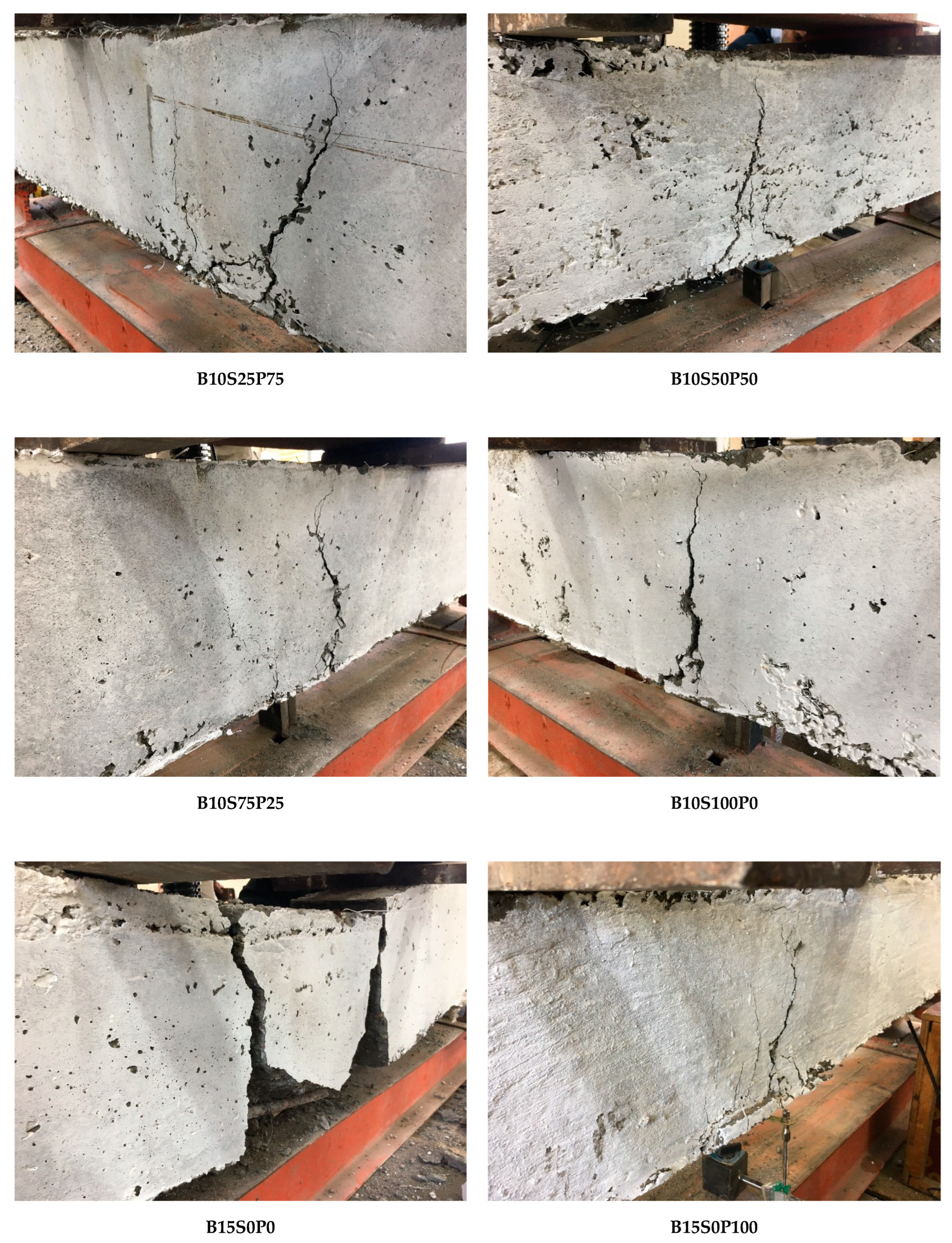
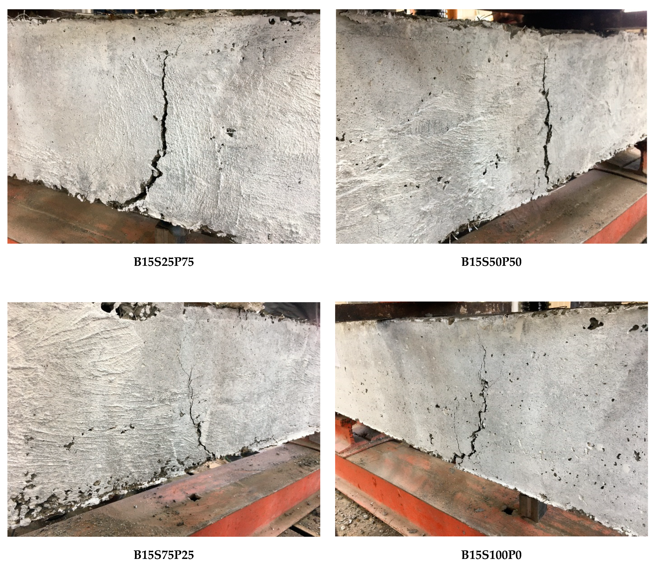
All tested lap-spliced specimens failed in bonding along the length of the splice. The failure mode observed for all specimens was splitting. The cracking generally occurred at the constant moment region of the specimen. All specimens showed fundamentally similar cracking behavior regardless of the type and relative percentage of fibers. The tested lap-spliced specimens are shown in Figure 10. The plain concrete specimens developed longitudinal splitting cracks on the bottom and sides. After the splitting cracks formed, the load carrying capacity of the beam specimen dropped rapidly. Despite the fiber-reinforced concrete (FRC) specimens failing as bottom-and-side splits, the cracks propagated more slowly, and bond failure was relatively less sudden than the plain concrete specimens.

6.2. Load-Deflection Behavior

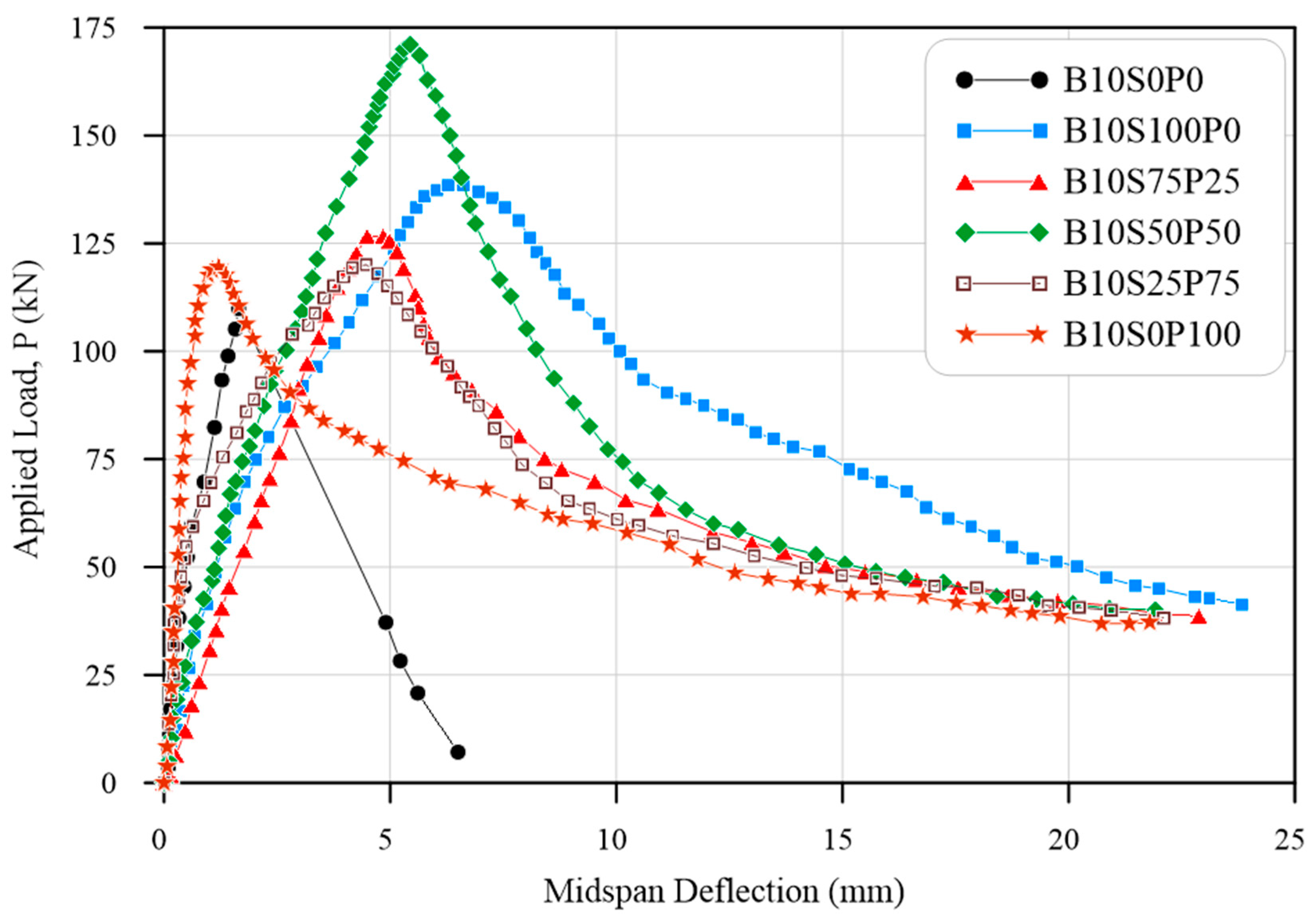
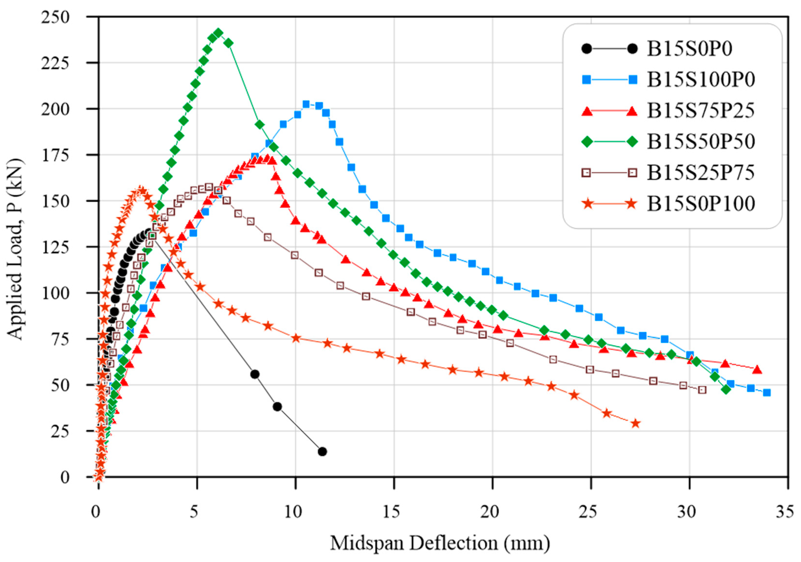
The load-deflection responses of the specimens include three stages: a stiff pre-cracking stage, a post-cracking stage from cracking up to splitting bond failure, and a post-failure stage with slowly deteriorating stiffness. The applied load versus the midspan deflection of specimens in Groups 1 and 2 are shown in Figure 11 and Figure 12. Although the fibers had a marginal effect on the first cracking strength of the fiber-reinforced recycled-aggregate (FR-RA) concrete, their fiber-bridging effect clearly improved the post-cracking behavior of the FR-RA concrete. Post-splitting ductility was significantly improved by fiber reinforcement.
In the case of a small length of lap splices of 10 db, the increase in the ultimate load capacity of the FRC beam specimens ranges between 8% and 53% in comparison to that of a plain beam specimen. However, in the case of a larger lap splice length of 15 db, the increase in the ultimate load capacity of the FRC beam specimens ranges between 17% and 79% in comparison to that of a plain beam specimen. The effect of fibers on the ultimate load of the beam specimen with ls = 15 db is higher than that of ls = 10 db. As can be noted from Equation (1), the bond strength decreases linearly as the splice length increases. Therefore, the contribution of fibers in the bond strength increases as the splice length increases. For both lap splice lengths, the maximum increase in the ultimate strength is in the case of using 50% steel fibers and 50% polyolefin fibers.
From the results, it can be concluded that the use of 50% steel fibers and 50% polyolefin fibers gives the highest bond strength, and this fiber percentage is effective also with a small lap splice length. On the other hand, the ductility of the FR-RA concrete is substantially improved for all the cases of various percentages of steel and polyolefin fibers.

6.3. Bond Strength

The maximum tensile stress in the reinforcement bars was determined according to a linear elastic cracked section analysis. The bond stress was assumed to be uniformly distributed over the length of the splice; thus, the following relationship can be used to determine the bond stress:
u = A b f s π d b l s = f s d b 4 l s
where u is the average bond stress; d b and A b are the nominal diameter and the area of the reinforcement bars, respectively; f s is the stress in the reinforcement bars at failure; and l s is the splice length (10 db or 15 db). The test results including the ultimate loads Pu and the corresponding measured midspan deflection Du, the calculated steel stress fs, the calculated bond strength (utest) from Equation (1), the normalized bond strength to ( f c ) 1 / 4 , the bond ratio, and the failure mode are presented in Table 8. The bond ratio is the ratio between the normalized bond strength of the FR-RA concrete specimen and the plain RA concrete specimen in the same group. It is important to note that Darwin et al. [37] found that ( f c ) 1 / 4 is more accurate than ( f c ) 1 / 2 in representing the effect of concrete strength on bond strength for concrete with a compressive strength between 17 and 110 MPa.
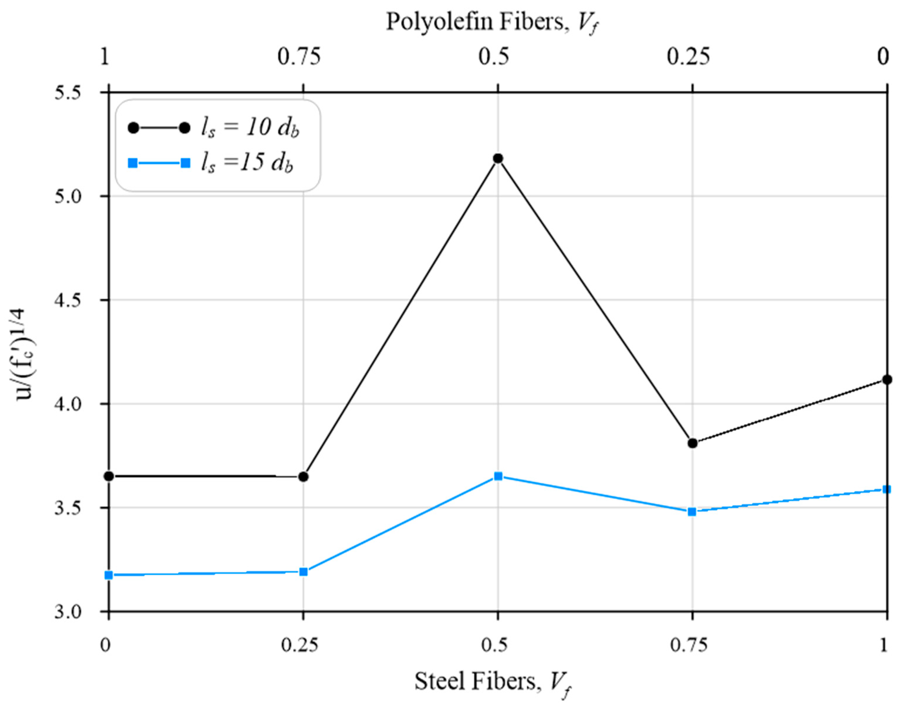
In some specimens, the reinforcement bars were yielded before the bond failure, which are marked with an asterisk in Table 8. For these specimens, the steel stress was taken as the yield stress of the bar to calculate the bond stress in Equation (1). The variations in normalized bond stress and bond ratio versus various ratios of steel–polyolefin fibers are plotted in Figure 13 and Figure 14, respectively. The test results showed that the steel and polyolefin fibers increased the bond strength in comparison to the plain RAC. The increase in the bond strength could be attributed to the increase in the splitting tensile strength of FRC. The maximum increase in the bond strength was when a ratio of steel–polyolefin of 50–50% was used. The bond ratios for lap splice lengths of 10 db and 15 db were 1.53 and 1.34, respectively. In general, the effect of fibers on the bond strength in the case of ls = 15 db was more than that of ls = 10 db. The fiber reinforcement provides enhanced bond strength to the reinforcing bars by acting as transverse reinforcement.

6.4. Comparison between Theoretical and Experimental Results

For the purpose of comparison, the bond strength of tension-spliced bars embedded in plain unconfined concrete was calculated using empirical equations, Equations (2) and (3), presented by Orangun et al. [38,39] and Darwin et al. [40], respectively:
u f c = [ 0.1 + 0.25 c d b + 4.15 d b l s ]
u f c 4 = [ 0.23 + 0.46 c d b + 14.10 d b l s ] ( 0.1 c m c + 0.9 )
where c represents the smallest of the concrete bottom cover (cb), side cover (cso), or half the clear spacing between the bars (csi); cm is the largest value of cb and the smallest of cso or (csi + 6.0 mm).
The bond strength of tension-spliced bars embedded in fiber-reinforced concrete (FRC) was also calculated using Equation (4) presented by Harajli [41]. This equation is essentially the equation of Darwin et al. [40] including an additional term to incorporate the effect of fibers on the bond strength.
u f c 4 = 0.23 + 0.46 c d b + 14.10 d b l s + f c 4 ( 0.25 c d b V f l f d f )
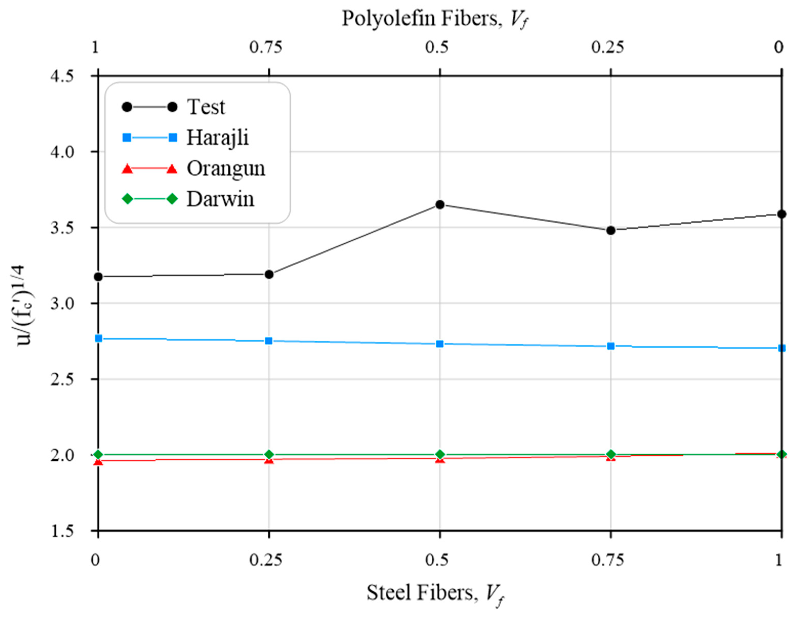
A summary of the average bond strength from the experimental test and the three empirical equations is presented in Table 9. This table also contains the normalized bond strength to ( f c ) 1 / 4 and the ratio between the calculated normalized bond strength of the specimen from the empirical equations and that from the test of the same specimen. The normalized bond stress versus volume fractions of steel and polyolefin fibers is also plotted in Figure 15 and Figure 16, for lap splice lengths of (10 db) and (15 db), respectively.
The results show that the equations presented by Orangun et al. [38,39] and Darwin et al. [40] gave a conservative bond strength estimation for the FR-RA concrete. However, the equation presented by Harajli [41] was relatively the most accurate estimation for the bond strength of FR-RA concrete because this equation includes the fiber effect. The average of the ratio between the calculated bond strengths using Orangun et al. [38,39] and Darwin et al. [40] equations and measured bond strengths for the specimens was 0.60 and 0.62 with standard deviation (SD) of 0.07 and 0.08, respectively. However, the average was 0.79 with SD of 0.08 using the Harajli [41] equation.

7. Conclusions

Based on the results of the bond strength of tension lap splices in recycled-coarse-aggregate-reinforced concrete strengthened with hybrid (steel–polyolefin) fibers, the following conclusions can be drawn:
  • The failure mode observed for all fiber-reinforced recycled-aggregate (FR-RA) concrete specimens was splitting. All specimens showed fundamentally similar cracking behavior regardless of the type and relative ratio of steel–polyolefin fibers.
  • The effect of fibers on the ultimate load capacity of the beam specimen with ls = 15 db was higher than that of ls = 10 db. In the case of ls = 15 db, the increase in the ultimate load capacity of the FRC beam specimens ranged between 8% and 53% in comparison to that of the plain beam specimen. However, in the case of ls = 15 db, it ranged between 17% and 79%.
  • The maximum increase in the bond strength of reinforcing bars embedded in FR-RA concrete was when a ratio of steel–polyolefin of 50–50% was used. In this ratio of fibers, the bond ratio was about 1.53 for the case of ls = 10 db; however, it was about 1.34 for the case of ls = 15 db.
  • In general, the effect of fibers on the bond strength in the case of ls = 15 db was more than that of ls = 10 db except for the ratio of steel–polyolefin of 50–50%.
  • The ductility of the FR-RA concrete was substantially improved for all the cases of various relative ratios of steel and polyolefin fibers.
  • The empirical equation proposed by Harajli [41] was a more accurate estimation of the bond strength of FR-RA concrete than that proposed by Orangun et al. [38,39] and Darwin et al. [40].

Author Contributions

Conceptualization, A.A.-H. and F.H.M.; methodology, A.A.-H. and F.H.M.; validation, A.A.-H., F.H.M. and K.Z.N.; formal analysis, A.A.-H.; investigation, A.A.-H., F.H.M. and K.Z.N.; resources, A.A.-H., F.H.M. and K.Z.N.; data curation, A.A.-H. and F.H.M.; writing—original draft preparation, A.A.-H.; writing—review and editing, A.A.-H. and K.Z.N.; funding acquisition, A.A.-H., F.H.M. and K.Z.N. All authors have read and agreed to the published version of the manuscript.

Funding

This research received no external funding.

Data Availability Statement

All data are contained within the article.

Conflicts of Interest

The authors declare no conflicts of interest.

Nomenclature

VariableDefinition
Abarea of rebars
cthe smallest of concrete bottom cover, side cover, or half the clear distance between the bars
cbconcrete bottom cover
csoconcrete side cover
csihalf the clear spacing between the bars
cmthe largest value of bottom cover and the smallest of side cover or half the clear distance between the bars + 6.0 mm
dbnominal diameter of rebar
dfdiameter of fiber
f c compressive strength of concrete
fsstress in the rebar at failure
lflength of fiber
lslap splice length
ubond strength
Vfvolume fraction of fibers

References

  1. Behera, M.; Bhattacharyya, S.K.; Minocha, A.K.; Deoliya, R.; Maiti, S. Recycled Aggregate from C&D Waste & Its Use in Concrete—A Breakthrough towards Sustainability in Construction Sector: A Review. Constr. Build. Mater. 2014, 68, 501–516. [Google Scholar] [CrossRef]
  2. Oikonomou, N.D. Recycled Concrete Aggregates. Cem. Concr. Compos. 2005, 27, 315–318. [Google Scholar] [CrossRef]
  3. Xiao, J.; Li, W.; Poon, C. Recent Studies on Mechanical Properties of Recycled Aggregate Concrete in China-A Review. Sci. China Technol. Sci. 2012, 55, 1463–1480. [Google Scholar] [CrossRef]
  4. Kisku, N.; Joshi, H.; Ansari, M.; Panda, S.K.; Nayak, S.; Dutta, S.C. A Critical Review and Assessment for Usage of Recycled Aggregate as Sustainable Construction Material. Constr. Build. Mater. 2017, 131, 721–740. [Google Scholar] [CrossRef]
  5. Kim, Y.; Hanif, A.; Kazmi, S.M.S.; Munir, M.J.; Park, C. Properties Enhancement of Recycled Aggregate Concrete through Pretreatment of Coarse Aggregates—Comparative Assessment of Assorted Techniques. J. Clean. Prod. 2018, 191, 339–349. [Google Scholar] [CrossRef]
  6. Australian Government. Productivity Commission, Waste Management: Productivity Commission Draft Report; Australian Government: Canberra, Australia, 2006.
  7. Etxeberria, M.; Vázquez, E.; Marí, A.; Barra, M. Influence of Amount of Recycled Coarse Aggregates and Production Process on Properties of Recycled Aggregate Concrete. Cem. Concr. Res. 2007, 37, 735–742. [Google Scholar] [CrossRef]
  8. Chakradhara Rao, M.; Bhattacharyya, S.K.; Barai, S.V. Influence of Field Recycled Coarse Aggregate on Properties of Concrete. Mater. Struct. Mater. Constr. 2011, 44, 205–220. [Google Scholar] [CrossRef]
  9. Ajdukiewicz, A.; Kliszczewicz, A. Influence of Recycled Aggregates on Mechanical Properties of HS/HPC. Cem. Concr. Compos. 2002, 24, 269–279. [Google Scholar] [CrossRef]
  10. Choi, H.; Choi, H.; Lim, M.; Inoue, M.; Kitagaki, R.; Noguchi, T. Evaluation on the Mechanical Performance of Low-Quality Recycled Aggregate through Interface Enhancement between Cement Matrix and Coarse Aggregate by Surface Modification Technology. Int. J. Concr. Struct. Mater. 2016, 10, 87–97. [Google Scholar] [CrossRef]
  11. Li, J.; Xiao, H.; Zhou, Y. Influence of Coating Recycled Aggregate Surface with Pozzolanic Powder on Properties of Recycled Aggregate Concrete. Constr. Build. Mater. 2009, 23, 1287–1291. [Google Scholar] [CrossRef]
  12. Katz, A. Properties of Concrete Made with Recycled Aggregate from Partially Hydrated Old Concrete. Cem. Concr. Res. 2003, 33, 703–711. [Google Scholar] [CrossRef]
  13. Gao, D.; Zhang, L.; Nokken, M. Compressive Behavior of Steel Fiber Reinforced Recycled Coarse Aggregate Concrete Designed with Equivalent Cubic Compressive Strength. Constr. Build. Mater. 2017, 141, 235–244. [Google Scholar] [CrossRef]
  14. Carneiro, J.A.; Lima, P.R.L.; Leite, M.B.; Toledo Filho, R.D. Compressive Stress-Strain Behavior of Steel Fiber Reinforced-Recycled Aggregate Concrete. Cem. Concr. Compos. 2014, 46, 65–72. [Google Scholar] [CrossRef]
  15. Akça, K.I.R.; Çakir, Ö.; Ipek, M. Properties of Polypropylene Fiber Reinforced Concrete Using Recycled Aggregates. Constr. Build. Mater. 2015, 98, 620–630. [Google Scholar] [CrossRef]
  16. Zhang, L.; Li, X.; Li, C.; Zhao, J.; Cheng, S. Mechanical Properties of Fully Recycled Aggregate Concrete Reinforced with Steel Fiber and Polypropylene Fiber. Materials 2024, 17, 1156. [Google Scholar] [CrossRef] [PubMed]
  17. Kong, X.; Yao, Y.; Wu, B.; Zhang, W.; He, W.; Fu, Y. The Impact Resistance and Mechanical Properties of Recycled Aggregate Concrete with Hooked-End and Crimped Steel Fiber. Materials 2022, 15, 7029. [Google Scholar] [CrossRef]
  18. Arslan, M.E. Effects of Basalt and Glass Chopped Fibers Addition on Fracture Energy and Mechanical Properties of Ordinary Concrete: CMOD Measurement. Constr. Build. Mater. 2016, 114, 383–391. [Google Scholar] [CrossRef]
  19. Yin, S.; Tuladhar, R.; Riella, J.; Chung, D.; Collister, T.; Combe, M.; Sivakugan, N. Comparative Evaluation of Virgin and Recycled Polypropylene Fibre Reinforced Concrete. Constr. Build. Mater. 2016, 114, 134–141. [Google Scholar] [CrossRef]
  20. Barros, J.A.O.; Cunha, V.M.C.F.; Ribeiro, A.F.; Antunes, J.A.B. Post-Cracking Behaviour of Steel Fibre Reinforced Concrete. Mater. Struct. Mater. Constr. 2005, 38, 47–56. [Google Scholar] [CrossRef]
  21. Buratti, N.; Mazzotti, C.; Savoia, M. Post-Cracking Behaviour of Steel and Macro-Synthetic Fibre-Reinforced Concretes. Constr. Build. Mater. 2011, 25, 2713–2722. [Google Scholar] [CrossRef]
  22. Banthia, N.; Sappakittipakorn, M. Toughness Enhancement in Steel Fiber Reinforced Concrete through Fiber Hybridization. Cem. Concr. Res. 2007, 37, 1366–1372. [Google Scholar] [CrossRef]
  23. Lee, C.J.; Salas Montoya, A.; Moon, H.; Kim, H.; Chung, C.-W. The Influence of the Hybridization of Steel and Polyolefin Fiber on the Mechanical Properties of Base Concrete Designed for Marine Shotcreting Purposes. Appl. Sci. 2021, 11, 9456. [Google Scholar] [CrossRef]
  24. Guo, Q.; Wang, H.; Gao, Y.; Jiao, Y.; Liu, F.; Dong, Z. Investigation of the Low-Temperature Properties and Cracking Resistance of Fiber-Reinforced Asphalt Concrete Using the DIC Technique. Eng. Fract. Mech. 2020, 229, 106951. [Google Scholar] [CrossRef]
  25. Mpalaskas, A.C.; Matikas, T.E.; Aggelis, D.G.; Alver, N. Acoustic Emission for Evaluating the Reinforcement Effectiveness in Steel Fiber Reinforced Concrete. Appl. Sci. 2021, 11, 3850. [Google Scholar] [CrossRef]
  26. Voutetaki, M.E.; Naoum, M.C.; Papadopoulos, N.A.; Chalioris, C.E. Cracking Diagnosis in Fiber-Reinforced Concrete with Synthetic Fibers Using Piezoelectric Transducers. Fibers 2022, 10, 5. [Google Scholar] [CrossRef]
  27. Xiao, J.; Falkner, H. Bond Behaviour between Recycled Aggregate Concrete and Steel Rebars. Constr. Build. Mater. 2007, 21, 395–401. [Google Scholar] [CrossRef]
  28. Choi, H.B.; Kang, K.I. Bond Behaviour of Deformed Bars Embedded in RAC. Mag. Concr. Res. 2008, 60, 399–410. [Google Scholar] [CrossRef]
  29. ACI Committee. Bond and Development of Straight Reinforcing Bars in Tension. ACI 408R-03; American Concrete Institute: Farmington Hills, MI, USA, 2003; pp. 48–49. [Google Scholar]
  30. Guoliang, B.A.I.; Shuhai, W.U.; Xiaowen, L.I. Investigation of Bond-Slip Behavior between Recycled Concrete and Steel Bars under Pull-out Test. In Proceedings of the 2nd International Conference on Waste Engineering and Management-ICWEM 2010, Shanghai, China, 13–15 October 2010; pp. 628–637. [Google Scholar]
  31. Butler, L.; West, J.S.; Tighe, S.L. The Effect of Recycled Concrete Aggregate Properties on the Bond Strength between RCA Concrete and Steel Reinforcement. Cem. Concr. Res. 2011, 41, 1037–1049. [Google Scholar] [CrossRef]
  32. Kim, Y.; Sim, J.; Park, C. Mechanical Properties of Recycled Aggregate Concrete with Deformed Steel Re-Bar. J. Mar. Sci. Technol. 2012, 20, 5. [Google Scholar] [CrossRef]
  33. Morohashi, N.; Sakurada, T.; Yanagibashi, K. Bond Splitting Strength of High-Quality Recycled Coarse Aggregate Concrete Beams. J. Asian Archit. Build. Eng. 2007, 6, 331–337. [Google Scholar] [CrossRef]
  34. ACI Committee 318. Building Code Requirements for Structural Concrete and Commentary (ACI 318M-19); Concrete Institute: Farmington Hills, MI, USA, 2019; Volume 552. [Google Scholar]
  35. Wu, Z.; Khayat, K.H.; Shi, C. How Do Fiber Shape and Matrix Composition Affect Fiber Pullout Behavior and Flexural Properties of UHPC? Cem. Concr. Compos. 2018, 90, 193–201. [Google Scholar] [CrossRef]
  36. ASTM C 33-18; Designation: C33/C33M—18 Standard Specification for Concrete Aggregates. ASTM International: West Conshohocken, PA, USA, 2018.
  37. Darwin, D.; Zuo, J.; Tholen, M.L.; Idun, E.K. Development Length Criteria for Conventional and High Relative Rib Area Reinforcing Bars. ACI Struct. J. 1996, 93, 347–359. [Google Scholar]
  38. Orangun, C.O.; Jirsa, J.O.; Breen, J.E. The Strength of Anchor Bars: A Reevaluation of Test Data on Development Length and Splices; Research Report No. 154-3F; Center for Highway Research, University of Texas at Austin: Austin, TX, USA, 1975; p. 78. [Google Scholar]
  39. Orangun, C.O.; Jirsa, J.O.; Breen, J.E. Reevaluation of Test Data on Development Length and Splices. In International Concrete Abstracts Portal; ACI Journal: Farmington Hills, MI, USA, 1977; Volume 74, pp. 114–122. [Google Scholar] [CrossRef]
  40. Darwin, D.; Lutz, L.A.; Zuo, J. Recommended Provisions and Commentary on Development and Lap Splice Lengths for Deformed Reinforcing Bars in Tension. ACI Struct. J. 2005, 102, 892–900. [Google Scholar] [CrossRef]
  41. Harajli, M.H. Bond Behavior in Steel Fiber-Reinforced Concrete Zones under Static and Cyclic Loading: Experimental Evaluations and Analytical Modeling. J. Mater. Civ. Eng. 2010, 22, 674–686. [Google Scholar] [CrossRef]
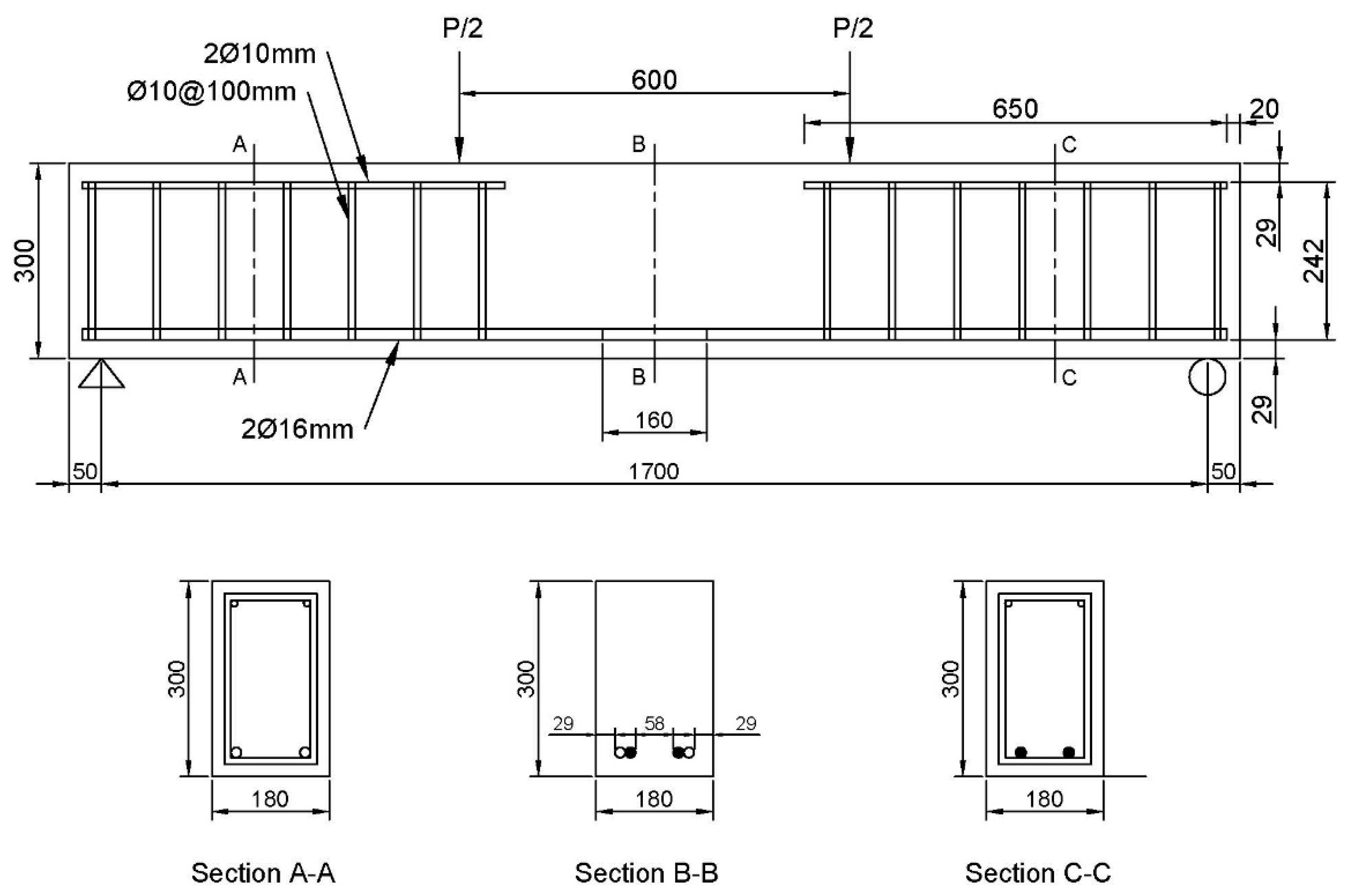
Figure 1. Beam specimen details for group (1) with splice length of 10 d b (160 mm).
Fibers 12 00060 g001
Figure 2. Beam specimen details for group (2) with splice length of 15 d b (240 mm).
Fibers 12 00060 g002
Figure 3. Reinforcement of lap-spliced beam specimen.
Fibers 12 00060 g003
Figure 4. Steel and polyolefin fibers.
Fibers 12 00060 g004
Figure 5. Particle sizes of recycled concrete aggregate (RCA).
Fibers 12 00060 g005
Figure 6. Grading curve of the coarse recycled concrete aggregate (RCA).
Fibers 12 00060 g006
Figure 7. Concrete test specimens.
Fibers 12 00060 g007
Figure 8. Lap-spliced beam specimens. (a) Beams during casting (b) Beams after demolding.
Fibers 12 00060 g008
Figure 9. Test setup for lap-spliced beam testing. (a) Photo. (b) Schematic representation.
Fibers 12 00060 g009aFibers 12 00060 g009b
Figure 10. Tested lap-spliced beams made of recycled-aggregate-reinforced concrete.
Fibers 12 00060 g010aFibers 12 00060 g010bFibers 12 00060 g010c
Figure 11. Applied load vs. midspan deflection for Group 1.
Fibers 12 00060 g011
Figure 12. Applied load vs. midspan deflection for Group 2.
Fibers 12 00060 g012
Figure 13. Normalized bond stress versus various ratios of steel–polyolefin fibers.
Fibers 12 00060 g013
Figure 14. Bond ratio versus various ratios of steel–polyolefin fibers.
Fibers 12 00060 g014
Figure 15. Bond stress versus various range of steel–polyolefin fibers for ls = 10 db.
Fibers 12 00060 g015
Figure 16. Bond stress versus various range of steel–polyolefin fibers for ls = 15 db.
Fibers 12 00060 g016
Table 1. Summary of the splice beams.
Group
No.
Specimen
ID
Lap Splice LengthSteel Fiber
Percentage (%)
Polyolefin Fiber Percentage (%)
1B10S0P010 d b 00
B10S100P010 d b 1000
B10S75P2510 d b 7525
B10S50P5010 d b 5050
B10S25P7510 d b 2575
B10S0P10010 d b 0100
2B15S0P015 d b 00
B15S100P015 d b 1000
B15S75P2515 d b 7525
B15S50P5015 d b 5050
B15S25P7515 d b 2575
B15S0P10015 d b 0100
Table 2. Rebar properties.
Rebar Diameter
(mm)
Yield Strength f y (MPa)Ultimate Strength
f u (MPa)
Elongation
(%)
1047062011.3
1652269510.2
Table 3. Properties of used fibers.
Fiber TypesLength (mm)Diameter (mm)Aspect Ratio
Hooked-end steel350.5563.6
Macro-polyolefin600.8471.4
Table 4. Details of materials used in concrete mix.
Cement
(kg/m3)
Sand
(kg/m3)
RCA
(kg/m3)
Water
(kg/m3)
Superplasticizer
(kg/m3)
w/c
40560811351824.050.42
Table 5. Cement physical properties.
Physical PropertiesTest ResultLimits of ASTM C150-04
Specific surface area (Blaine method) (m2/kg)312Not less than 280
Setting time
(Vicat method)
(min)
Initial setting126More than 45
Final setting321Less than 375
Compressive strength
(MPa)
3 days13.8More than 12
7 days23.4More than 19
Table 6. Chemical composition and main compounds of cement.
Oxide Composition% By WeightLimits of ASTM C150-04
Lime (CaO)62.3---
MgO2.046.0 (max)
Fe2O34.09---
SO32.10---
C3A2.813.0 (max)
C4AF14.225.0 (max)
Loss on ignition2.423.0 (max)
Insoluble residue0.590.75 (max)
Table 7. Mechanical properties of concrete.
Mix No.Steel Fiber Ratio (%)Polyolefin Fiber Ratio (%)Compressive Strength, fcu (MPa)Compressive Strength, f c (MPa)Tensile Strength, fct (MPa)Flexural Strength, ft (MPa)
10036.4130.342.6816.13
2100041.4534.544.3023.80
3752539.6633.053.8923.28
4505038.6932.244.8625.54
5257538.2631.883.7521.69
6010037.4831.233.4717.93
Table 8. Summary of the test results.
Group No.Specimen IDConcrete Strength, f c (MPa)Ultimate Load, Pu (kN) Midspan Deflection at Pu (mm)Steel Stress, fs (MPa) Bond Strength, utest (MPa)utest/ ( f c ) 1 / 4 Bond RatioFailure Mode
1 B10S0P030.34109.901.65317.837.953.391.00SP
B10S100P034.54138.456.29399.219.984.121.22SP
B10S75P2533.05126.624.49365.459.143.811.13SP
B10S50P5032.24171.035.44493.9212.355.181.53SP
B10S25P7531.88120.074.47346.838.673.651.08SP
B10S0P10031.23119.471.21345.288.633.651.08SP
2 B15S0P030.34132.642.56383.586.392.721.00SP
B15S100P034.54202.5210.53522.00 *8.703.591.32SP + Y
B15S75P2533.05173.498.57500.758.353.481.28SP
B15S50P5032.24241.116.07522.00 *8.703.651.34SP + Y
B15S25P7531.88157.495.60454.937.583.191.17SP
B15S0P10031.23155.832.09450.357.513.181.17SP
* Reinforcement bar has yielded; SP: splitting of concrete; Y: yield of reinforcement bar.
Table 9. Comparison of experimental and theoretical bond strength values.
Group No.Specimen IDConcrete Strength, f c (MPa)Ultimate Load, Pu (kN) P u ( f c ) 1 / 4 Normalized Load RatioTest and Calculated Bond Stress, u (MPa)Normalized Bond Stress, u / ( f c ) 1 / 4 ucalc/utest
TestOrangunDarwinHarajliTestOrangunDarwinHarajliOrangunDarwinHarajli
1B10S0P030.34109.9046.831.007.955.335.815.813.392.272.472.470.670.730.73
B10S100P034.54138.4557.111.229.985.696.007.694.122.352.473.170.570.600.77
B10S75P2533.05126.6252.811.139.145.575.937.643.812.322.473.190.610.650.84
B10S50P5032.24171.0371.781.5312.355.505.897.635.182.312.473.200.450.480.62
B10S25P7531.88120.0750.531.088.675.475.887.663.652.302.473.220.630.680.88
B10S0P10031.23119.4750.541.088.635.415.857.663.652.292.473.240.630.680.89
2B15S0P030.34132.6456.521.006.394.574.704.702.721.952.002.000.710.740.74
B15S100P034.54202.5283.541.488.704.884.866.553.592.012.002.700.560.560.75
B15S75P2533.05173.4972.361.288.354.774.806.513.481.992.002.720.570.580.78
B15S50P5032.24241.11101.191.798.704.714.776.513.651.982.002.730.540.550.75
B15S25P7531.88157.4966.281.177.584.694.766.543.191.972.002.750.620.630.86
B15S0P10031.23155.8365.921.177.514.644.746.553.181.962.002.770.620.630.87
Mean0.600.620.79
SD0.070.080.08
Disclaimer/Publisher’s Note: The statements, opinions and data contained in all publications are solely those of the individual author(s) and contributor(s) and not of MDPI and/or the editor(s). MDPI and/or the editor(s) disclaim responsibility for any injury to people or property resulting from any ideas, methods, instructions or products referred to in the content.