Abstract
The utilization and incorporation of glass fiber-reinforced plastics (GFRP) in structural applications and architectural constructions are progressively gaining prominence. Therefore, this paper experimentally and numerically investigates the use of GFRP I-beams in conjunction with concrete slabs to form composite beams. The experimental design incorporated 2600 mm long GFRP I-beams which were connected compositely to concrete slabs with a 500 mm width and 80 mm thickness. The concrete slabs are categorized into two groups: concrete slabs cast using normal-strength concrete (NSC), and concrete slabs prepared using high-strength concrete (HSC). Various parameters like the type of concrete (normal and high-strength concrete), type of stiffeners bonded to the composite section (bolt–epoxy or bolt only), and inclusion of corrugated metal sheets were investigated. To obtain the full shear connection between the GFRP I-sections and concrete slabs, two rows of shear connectors in the form of bolts were utilized. These shear connectors were erected to the top flange of the GFRP I-sections to compositely connect between the GFRP I-beams and the concrete slabs as well as the corrugated metal sheets. The strengthening of the shear webs of GFRP I-beams with GFRP T-section stiffeners resulted in an enhancement in the flexural and shear strength. The failure loads in the case of the bolt–epoxy connection for the stiffeners were 8.2% and 10.0% higher than those in the case of bolt only when the concrete compressive strengths were 20.1 MPa and 52.3 MPa, respectively. Moreover, the effect of the concrete compressive strength was vital where the failure loads increased by 79.9% and 77.1% when HSC was used instead of NSC for the cases of bolt–epoxy and bolt only, respectively. The epoxy adhesive used in conjunction with mechanical connectors, specifically bolts, resulted in sufficient composite action and delayed shear failure within the web of the GFRP beam. For the specimens with bolt–epoxy connection, strain levels in the concrete slabs were consistently higher than in the other specimens with bolts alone at the same loading level. The concrete slabs integrated with HSC registered strain levels that were 20.0% and 21.8% greater for bolt–epoxy and bolt-only connections, respectively, when compared to those using normal-strength concrete (NSC). This discrepancy can likely be credited to the enhanced composite interaction between the concrete slabs and the GFRP I-beams. In addition, ABAQUS software (version 6.2) was used to develop FE models to analyze the tested composite beams and provide a parametric study using the verified models.
1. Introduction
The demand for sustainable and durable construction materials has led to the exploration of innovative solutions, such as the combination of pultruded GFRP profiles and traditional concrete elements. Pultruded GFRP offers a high strength-to-weight ratio, corrosion resistance, and ease of manufacturing, making it an attractive material for civil engineering applications [1,2,3]. The integration of pultruded glass fiber-reinforced polymer (GFRP) profiles with concrete structures has gained significant attention in recent years due to the excellent mechanical properties and corrosion resistance of GFRP materials. The economic efficiency of pultrusion can be significantly improved by operating the process at higher pulling speeds; through experimental study, researchers have analyzed the relationships between the pulling speed, morphology, and mechanical properties of pultruded glass fiber/vinyl ester resin structural composites [4]. This literature review delves into the flexural behavior of pultruded GFRP I-section composites when utilized as strengthening elements for concrete slabs. Specifically, it explores the effects of incorporating GFRP T-section stiffeners on the overall performance of composite beams.
There has been a significant increase in the investigation of fiber-reinforced polymer (FRP) prismatic sections for the purpose of achieving composite action with concrete. This trend is observed in conjunction with the growing utilization of FRP in both established and emerging applications within the realm of concrete structures. Over time, a considerable number of scholars have conducted research on the structural behavior of hybrid beams that consist of a combination of FRP and concrete materials. One study conducted an examination of a novel hybrid design for FRP–concrete beams, which involved both wrapped and unwrapped beams. The findings indicated that the wrapped beams exhibited a significant increase in load-carrying capacity, approximately twice as much as the unwrapped beams. Additionally, the wrapped beams demonstrated a noteworthy improvement in ductility compared to the unwrapped beams [5,6,7,8]. Based on a prior investigation encompassing diverse bonding parameters and combinations of FRP–concrete for beams, it was observed that composite beams exhibited notably reduced deflections and greater ultimate failure loads compared to conventional beams [9].
Prior research has investigated various aspects of RC composite beams, which are characterized by a concrete block on the upper side and an I-beam featuring GFRP protrusions on the lower side. Notably, improvements in ultimate capacity, ductility, and stiffness were observed [10,11,12]. However, a drawback of this composite beam was the occurrence of web instabilities during loading. Furthermore, its performance in fire was subpar due to the exposure of the I-beam to air without the protective covering of concrete. An alternative configuration for the composite beam was proposed, involving the encapsulation of the GFRP I-beam within the RC cross-section. Previous experimental studies have focused on these composite beams, conducting tests on concrete slabs to evaluate the advantages of replacing traditional steel-reinforced slabs with pultruded GFRP grating sections [13]. This approach demonstrated a reduction in the local buckling failure of embedded grid sections due to concrete confinement. The structural behavior of GFRP prismatic beams, attached at the top to concrete slabs using various GFRP profiles (including rectangular and I-sections) in composite action with concrete, has been examined [14]. Significantly, the plain GFRP I-section beam exhibited higher stiffness than the GFRP rectangular section beam, but achieved a lower ultimate failure load. Encasing the GFRP I-beam provided both flexural and increased shear strength [15]. Additionally, the slip between the concrete and the I-beam was found to decrease the load-carrying capacity, underscoring the crucial role of the connection between the FRP profile and concrete in influencing flexural behavior [16]. In a previous study, the impact of shear connectors on the flexural behavior of composite beams featuring GFRP I-sections was explored [17]. The structural response of hybrid GFRP I-sections mechanically connected to RC slabs, incorporating different cross-section geometries (with a GFRP I-section encased in concrete and a GFRP I-section connected to an RC slab by shear studs), was experimentally examined. Notably, a stiffer mechanical connection provided lateral confinement to the profile, resulting in half the slip values compared to configurations without shear studs [17].
Since web instabilities during loading were the disadvantages of the GFRP I-beams compositely connected to the concrete slabs, this phenomenon needs additional investigation so that we might overcome this mode of failure. Hence, this study systematically explores the practical application of glass fiber-reinforced polymer (GFRP) I-beams combined with concrete slabs to create composite beams, employing both experimental and numerical analyses. The experimental design incorporated GFRP I-beams, which were connected compositely to concrete slabs. The concrete slabs are categorized into two groups: concrete slabs cast using normal-strength concrete (NSC) and concrete slabs prepared using high-strength concrete (HSC). Various parameters were used, like the type of concrete (normal- and high-strength concrete), type of stiffeners bonded to the composite section (bolt–epoxy or bolt only), and inclusion of corrugated metal sheets. Moreover, ABAQUS software was used to develop FE models to analyze the tested composite beams and provide a parametric study using the verified models.
2. Experimental Work
The main purpose of the experimental configuration was to examine and explore the behavior of GFRP I-sections when acting in conjunction, with concrete while considering different parameters and combinations. Table 1 lists the tested specimens with different configurations.

Table 1.
Details of the tested specimens.
2.1. Details of the Tested Specimens
The experimental design incorporated 2600 mm long GFRP I-beams which were connected compositely to concrete slabs with a 500 mm width and 80 mm thickness. The shear span-to-depth ratio was 5.6. The concrete slabs are categorized into two groups: concrete slabs cast using normal-strength concrete (NSC), and concrete slabs prepared using high-strength concrete (HSC). Various parameters were used, like the type of concrete (normal- and high-strength concrete), type of stiffeners bonded to the composite section (bolt–epoxy or bolt only), and inclusion of corrugated metal sheets with a thickness of 0.5 mm and yield stress of 426 MPa. Figure 1 provides the dimensions and details of the tested GFRP I-sections. These dimensions were selected to induce compression failure in the concrete slabs and ensure that the neutral axis aligns with the concrete slabs. This mode of failure was selected because it demonstrates the most significant degree of ductility among the various potential failure scenarios [18].

Figure 1.
Details and dimensions of the specimens and their components (all dimensions are in mm).
To obtain the full shear connection between the GFRP I-sections and concrete slabs, two rows of shear connectors in the form of bolts (grade 8.8 bolts) were utilized. These shear connectors were erected to the top flange of the GFRP I-sections at 260 mm longitudinal spacing and 50 mm transverse spacing to compositely connect between the GFRP I-beams and the concrete slabs as well as the corrugated metal sheets. These shear connectors were 75 mm in length and 12 mm in diameter. Every bolt was securely fastened into the upper flange of the GFRP I-beams by means of a hole, and subsequently tightened using nuts positioned above and beneath the flange. Per BS 3692, grade 8 nuts with a yield stress of 628 MPa were employed for this purpose. After fastening the bolts and the corrugated steel sheet, the formwork was fabricated (see Figure 2a) and the steel reinforcement was erected as 7Ø12 in the longitudinal direction with a spacing of 80 mm, as shown in Figure 2b. Moreover, steel rebars of 10 mm in diameter and 80 mm spacing were arranged along the length of each specimen. Finally, the concrete slabs were poured and subjected to a water-curing process for 14 days.
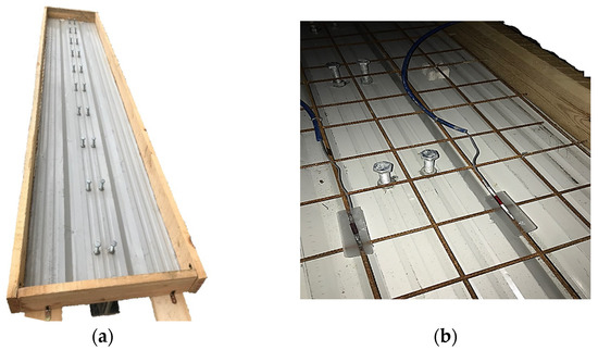
Figure 2.
(a) Formwork and (b) steel reinforcement.
Local buckling in the prominent flange of the GFRP section is the primary factor influencing its flexural stress [10]. To avoid this buckling during testing, GFRP stiffeners were incorporated according to Nkosi [19]. Therefore, the composite beams were detached and subsequently affixed to stiffeners in the form of T-section GFRP using bolts and epoxy, as shown in Figure 3. In the case using bolts, grade 8.8 bolts measuring 40 mm in length and 8 mm in diameter were used between the stiffeners and the GFRP I-beams. Additionally, grade 8 nuts with an fy = 628 MPa were employed (per BS 3692). In the case of using epoxy, epoxy adhesives, denoted Epoxy A and Epoxy B, which consist of a resin and a hardener, were utilized. The mixing process of the two adhesives was conducted based on the instructions provided by the manufacturer. Before the bonding process, the surfaces were prepared by roughening them with sandpaper and applying acetone solvent to the surfaces. The epoxy thickness was 2 mm between the GFRP web and the stiffeners. Finally, the composite beams were left in ambient air for an additional 14 days before testing.
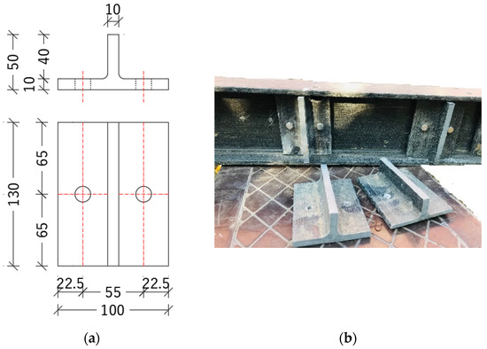
Figure 3.
GFRP stiffeners: (a) dimensions and details and (b) GFRP stiffeners attached to the GFRP beam.
2.2. Materials
The GFRP I-beams utilized in this research were procured from Dura Composites Ltd., a globally recognized manufacturer of FRP products (Essex, United Kingdom). The I-beams were manufactured from isophthalic polyester resins that were reinforced with E-glass fibers. Table 2 presents the mechanical and geometric characteristics of the pultruded GFRP I-section. The provided mechanical compressive and tensile properties were determined by standard testing as specified in ASTM D695–15 [20] and ISO 527-4:2021 [21], respectively. The elastic modulus of GFRP was 27.1 GPa, while it was 200 GPa for the steel reinforcement rebars. Due to the lower stiffness of GFRP compared to the steel and CFRP rebars, the deflections are larger at the same loading level [22].
Table 2.
Geometrical and mechanical properties of the pultruded GFRP I-sections.
Normal- and high-strength concrete mixes were used to prepare the concrete slabs of the composite beams. The concrete mix proportions (by weight) were 1.0:1.4:2.1:0.3:0.015 for the NSC and 1.0:1.1:1.2:0.2:0.029 for the HSC. These proportions represent the ratios of cement, sand, coarse aggregate, water/cement ratio, and superplasticizer. Concrete cubes 150 mm × 150 mm × 150 mm were prepared and cured for 28 days according to BS 1881 [23]. During the curing process, the concrete specimens were kept in the plastic molds for 24 h. Following the extraction of the specimens, they were submerged in room-temperature water until a testing age of 28 days was attained. The average compressive strengths of concrete were 20.6 MPa and 52.1 MPa for the NSC and HSC, respectively.
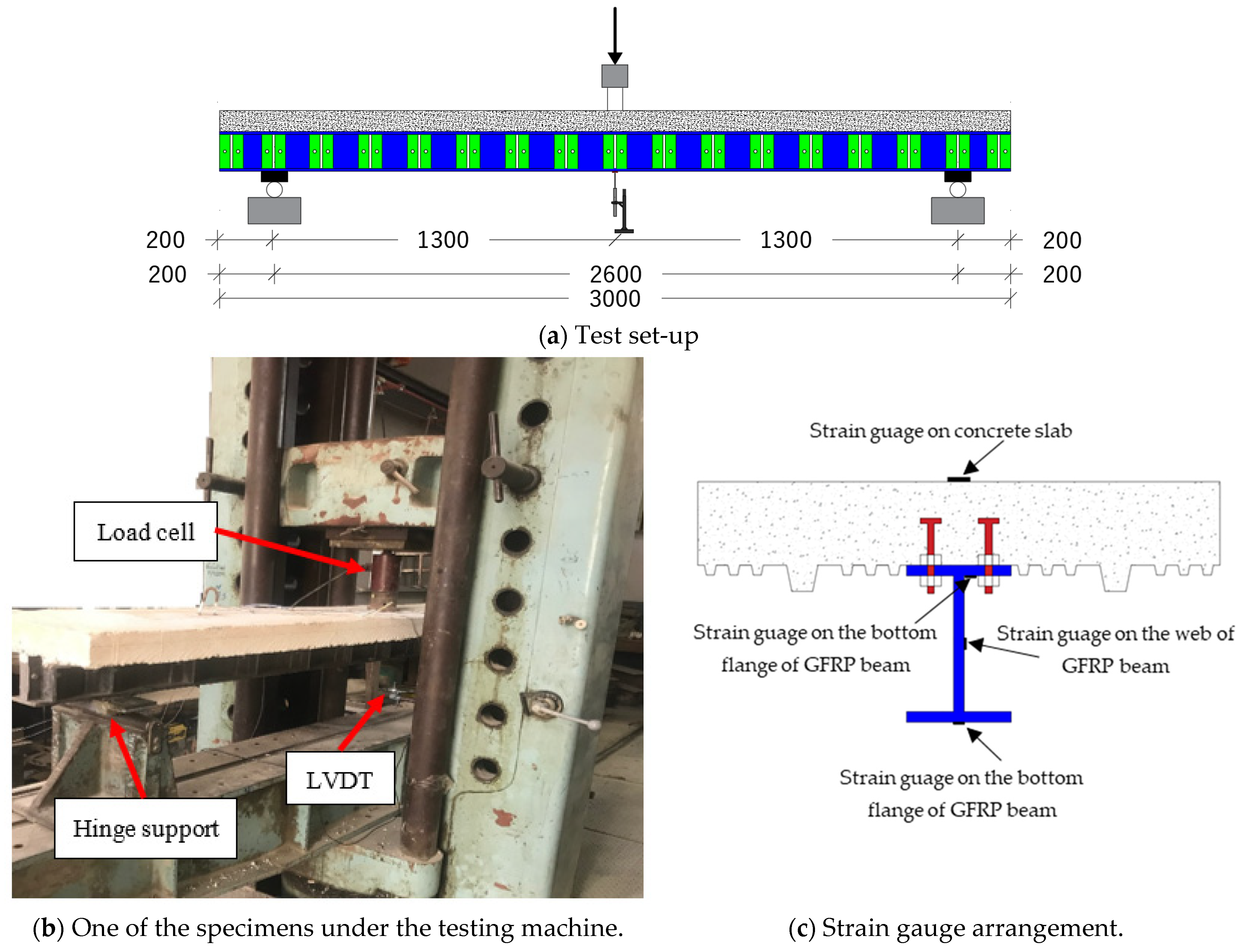
2.3. Test Setup and Instrumentations
The prepared composite beams were subjected to a three-point loading configuration using a hydraulic jack of 200 kN capacity, as illustrated in Figure 4. The applied load was recorded by a load cell which was attached to the hydraulic jack. The mid-span deflection for each specimen was recorded using a linear variable differential transformer (LVDT). Moreover, the strains in the concrete slabs, GFRP beams, steel rebars, and corrugated metal sheets were monitored during the tests using strain gauges. These strain gauges were strategically positioned at the mid-span of each specimen. Three strain gauges were attached to the GFRP beam of the composite specimen, specifically targeting the top flange, bottom flange, and mid-web. All instruments were connected to a data logger and the recorded readings were collected by a computer.
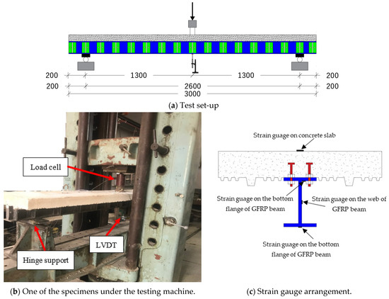
Figure 4.
Details, experimental setup and instrumentations.
3. Results and Discussions
3.1. Load–Deformation Relationships
The experimental results of the tested beams are listed in Table 3 in terms of the failure loads and the corresponding mid-span deflections, measured strains, and modes of failure. The failure loads in the case of bolt–epoxy connection for the stiffeners were 8.2% and 10.0% higher than those in the case of bolts only when the concrete compressive strengths were 20.1 MPa and 52.3 MPa, respectively. Moreover, the effect of the concrete compressive strength was vital, where the failure loads increased by 79.9% and 77.1% when the HSC was used instead of NSC for the cases of bolt–epoxy and bolt only, respectively.
Table 3.
Summary of the experimental results.
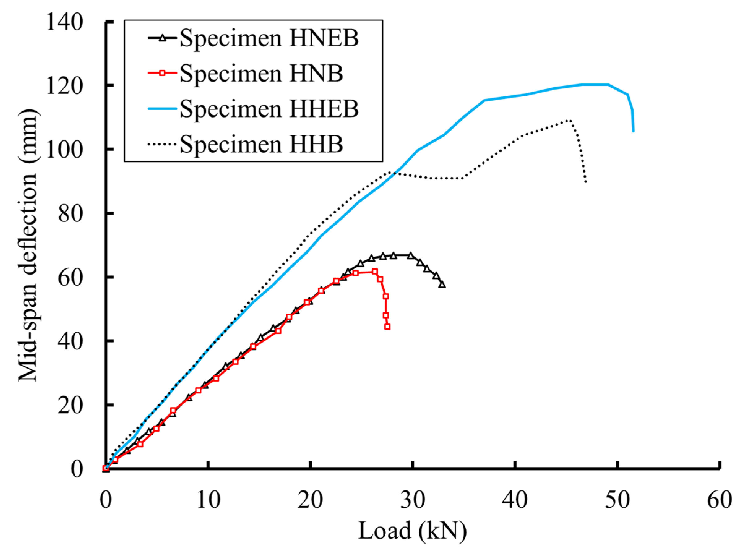
Table 3 displays the maximum deflection measurements for the tested beams. The beams reinforced with GFRP T-section stiffeners and secured with a bolt–epoxy combination exhibited a reduced deflection ratio compared to those beams that were solely bolted. Figure 5 illustrates the load–deflection curves for these beams. Beams with the bolt–epoxy connection method showcased superior performance, as evidenced by their higher stiffness values and increased failure loads, compared to the beams with just the bolted connection.
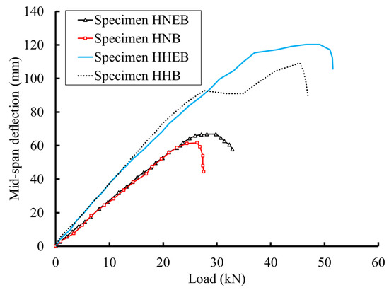
Figure 5.
Illustration of the load–deflection curves for the tested beams.
3.2. Strain Measurements
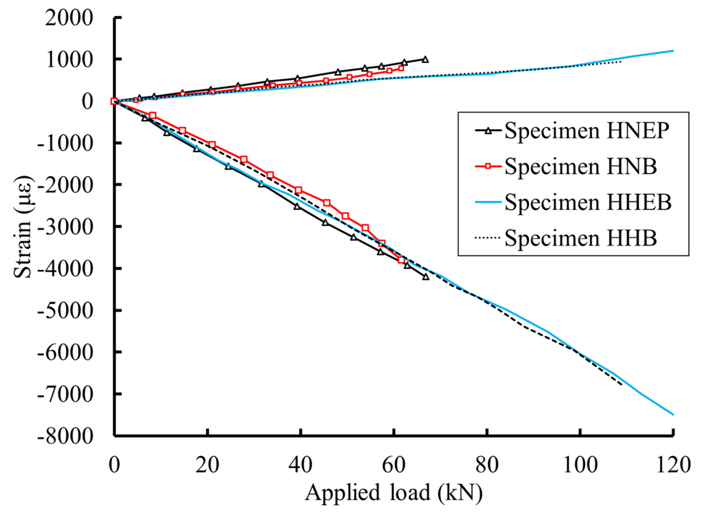
Figure 6 depicts the strains measured at the mid-span extreme fibers of the examined specimens. For specimens HNEB and HHEB, which used a bolt–epoxy connection, strain levels in the concrete slabs were consistently higher than in specimens HNB and HHB, which utilized bolts alone, given the same load level. This discrepancy can likely be credited to the enhanced composite interaction between the concrete slabs and the GFRP I-beams. Yet, this distinction became negligible when high-strength concrete (HSC) was applied. Contrastingly, concrete slabs integrated with HSC registered strain levels that were 20.0% and 21.8% greater for bolt–epoxy and bolt-only connections, respectively, when compared to those using normal-strength concrete (NSC). The elevated strain levels were linked to the amplified flexural capabilities introduced by the high-strength concrete.
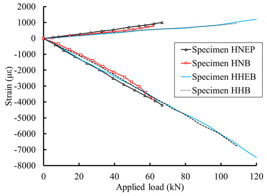
Figure 6.
Extreme fiber strain measurements.
3.3. Modes of Failure
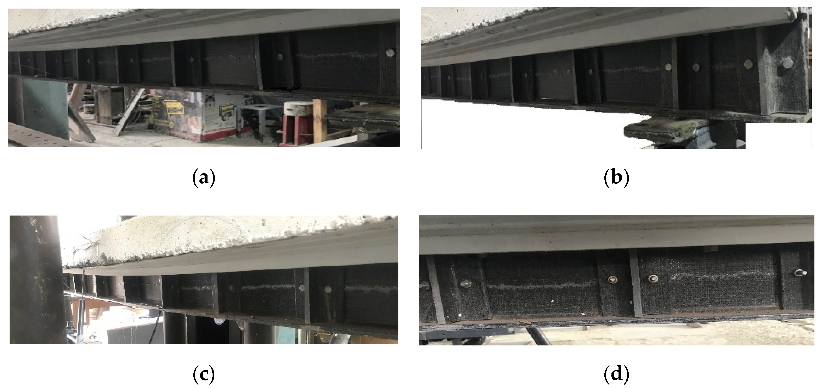
Each of the tested beams is predominantly fractured at the shear web joint located in the central region of the GFRP beam and proximate to the point loads on the composite beams. This type of failure can decisively be linked to the commencement and eventual development that led to the beams’ catastrophic breakage. Prior to complete failure, audible cues such as the cracking of the beam section and the shearing of fibers were evident. The breakage, following these sounds, was abrupt. The onset of failure originated from the bolt holes intended for the stiffeners. Notably, beams reinforced in the manner of HNEB and HHEB exhibited cracks between stiffener segments before the ultimate failure, thus providing a preliminary warning of their impending breakdown. Figure 7 captures the ultimate shear failure in the beams’ webs.
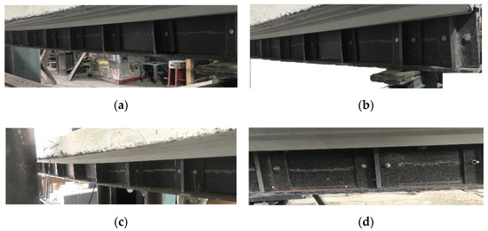
Figure 7.
Modes of failure of the tested specimens: (a) specimen HNB, (b) specimen HNEB, (c) specimen HHB, and (d) specimen HHEB.
4. Numerical Modeling
In this study, FE models were developed using the ABAQUS software [24] package to numerically investigate the behavior of the tested composite beams under the effect of static loading. The material and geometric nonlinearities were considered. The FE modeling involved the modeling of the several components of the composite beams including the slab, GFRP I-beam, shear connectors (between the GFRP I-beam and the slab), shear bolts (between the GFRP I-beam and the stiffeners), and GFRP stiffeners. The modeling approach employed 3D stress elements to accurately represent the behavior of each component.
4.1. Selection of Elements
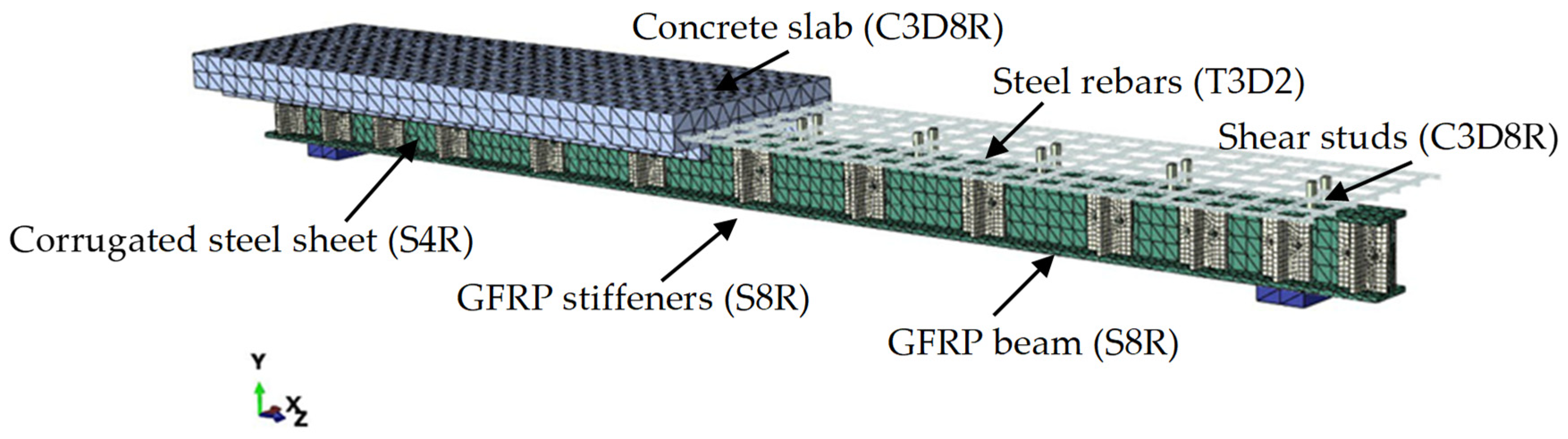
The representation of the concrete volume was achieved using an eight-node solid brick element (C3D8R) that incorporated 2 × 2 × 2 integration points. The longitudinal and transverse steel rebars of the concrete slabs were simulated by employing embedded two-node linear 3D truss elements (T3D2) [11]. The utilization of eight-node solid components (C3D8R) was also employed in the simulation of steel plates subjected to both the applied load and the resisting reactions, as depicted in Figure 8. The corrugated steel sheet was modeled using shell elements (S4R). The eight-node shell element S8R with reduced integration was used to simulate the GFRP I-beam and stiffeners. The shear connectors were modeled using general-purpose linear brick elements (C3D8R).
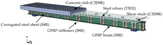
Figure 8.
The meshing of the FE model for the composite beam HNB.
It is noteworthy to emphasize that in the context of this numerical study, a perfect bond was assumed to exist between the surrounding concrete and the steel rebars, indicating complete compatibility. However, the bond between the GFRP beam surface and the concrete slab was simulated using surface-to-surface contact pairing. The contact property was represented by the tangential behavior with a penalty friction formulation. The tangential shear stress was adopted from the push-out test as 0.422 MPa [25] and the friction coefficient was used equally at 0.55, according to the test of Hadi and Yuan [15]. However, the full bond between the GFRP stiffeners and GFRP beams was assumed.
Mesh sensitivity analysis methods were employed to depict the load–displacement behavior of beam specimens. Various mesh sizes (10 mm, 15 mm, and 20 mm) were employed to assess the sensitivity of the simulation. The comparisons were based on the convergence errors and solving time. Following numerous iterations, a mesh size of 15 mm × 15 mm × 15 mm was opted for the concrete and CFRP elements as well as the loading steel plates (C3D8R size). The 15 mm mesh size was also adopted for the steel rebars to ensure compatibility with the surrounding concrete elements. Comparative analyses indicated that refining the mesh size had no discernible impact on displacement and load. Consequently, a 15 mm mesh size was selected for use in the simulations.
4.2. Material Modeling
In this analysis, we employed the concrete damage plasticity (CDP) model to simulate the response of the examined specimens. The CDP model factors in the phenomena of concrete cracking and crushing. The various damage parameters for cracking and crushing are listed in Table 4. These different parameters were established from previous analyses and implemented in this study [24,26]. The factors considered in this study included the dilation angle (φ), eccentricity (ϵ), the ratio of compressive strength to uniaxial pressure (biaxial) (fbo/fco), the coefficient (K), and the viscosity parameters (μ).
Table 4.
Input parameters for the CDP model [24,26].
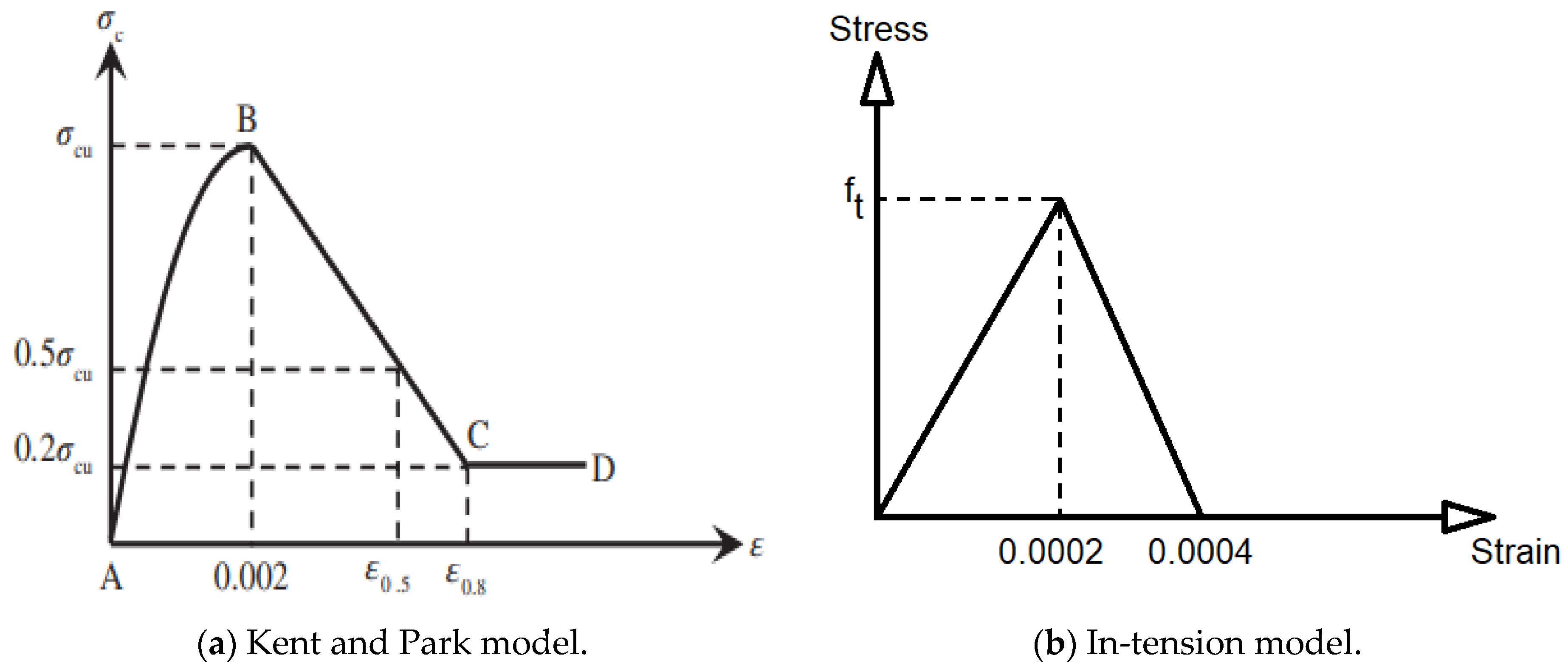
Figure 9 presents the stress-strain curves for concrete as per CEN [27]. This investigation used the Kent and Park [28,29] parabolic constitutive model for unconfined concrete, as shown in Figure 9a. Park [29] reported to equal 0.002, which was assumed in this study. The adopted relationship shows a parabolic increasing trend (A–B) for the hardening stage and a linear behavior (B–C) for the unconfined cylinder specimen, where and represent nominal compressive stress and strain, and and represent ultimate compressive strength and strain. The softening phase continued until 20% of the unconfined cylinder compressive strength (Point C) was reached, at which point the stress value could not drop, and perfect plastic behavior was anticipated (C–D).
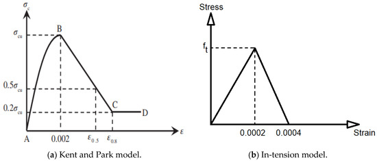
Figure 9.
The adopted stress–strain relationships for concrete.
Concrete was treated as quasi-brittle material under tension. Therefore, a two-phase constitutive model of pre-cracking and post-cracking (see Figure 9b) was proposed. The model adopted a linear–elastic stress-strain relationship up to the point of the failure stress threshold (i.e., the tensile strength of concrete, ft). The linear softening curve was implemented in the proposed model, as shown in Figure 9b.
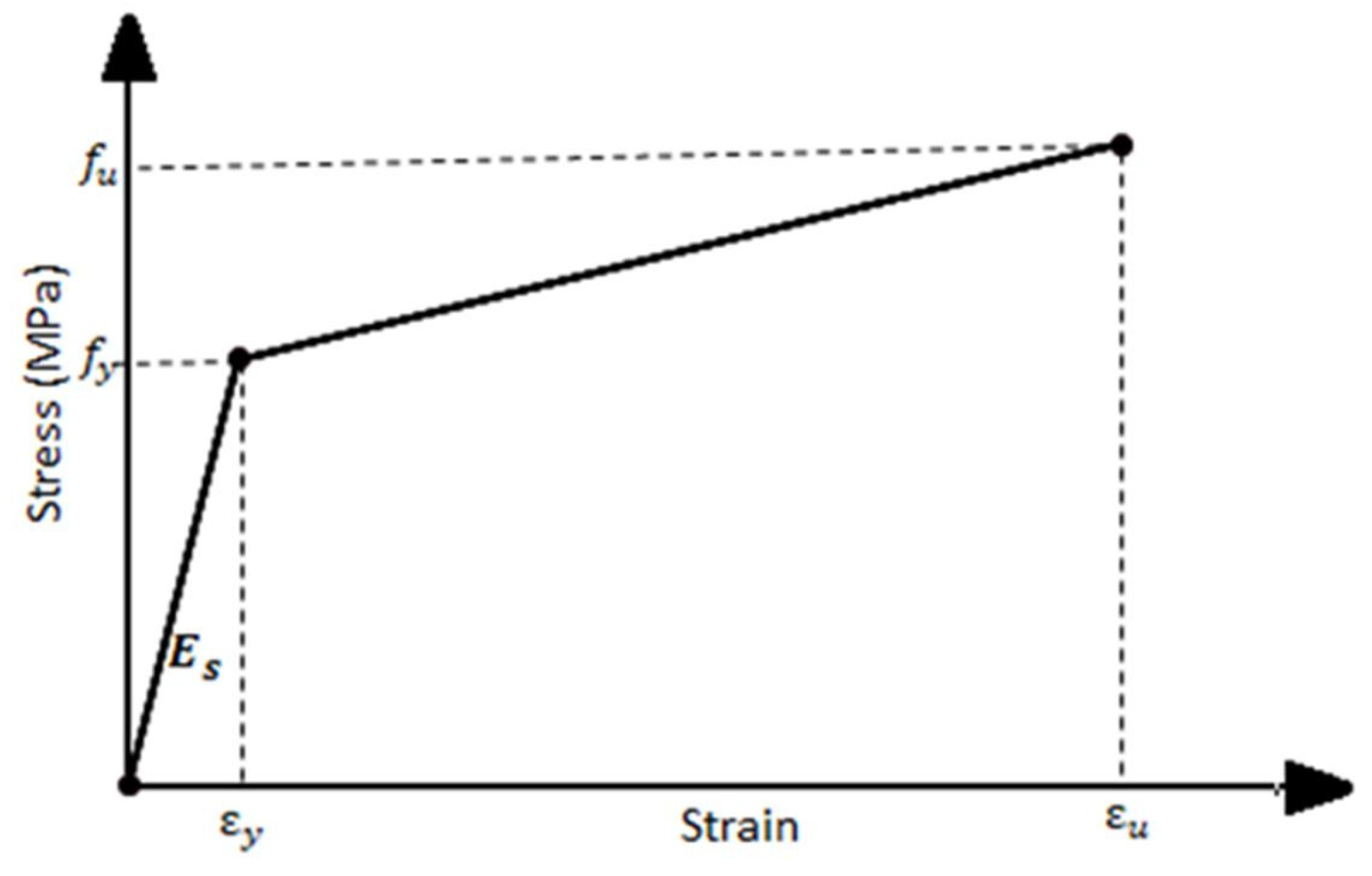
The bilinear relationship for longitudinal steel rebars was adopted in this study as depicted in Figure 10. The linear isotropic component is determined by the reinforcement’s elastic modulus and Poisson’s ratio as well as the yielding stress. The plastic component is characterized by yield stress (fy), ultimate stress (fu), and plastic strains.
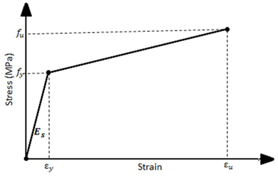
Figure 10.
Stress–strain relationship for steel rebars.
The behavior of the pultruded profiles was characterized by employing the progressive damage model in conjunction with a mixture of damage initiation criteria. Hashin’s criteria [30] determined when the pultruded profile (GFRP beam) degrades. After meeting damage conditions, the pultruded profile’s stiffness diminishes according to the damage evolution law. Table 5 lists the engineering constants for the elastic properties of GFRP material, strength properties for damage initiation criteria, and progressive damage model parameters for damage evolution (fracture energy) and damage stabilization (viscosity coefficients). Based on the fiber and matrix type and trial and error, the listed values in Table 5 were derived from experiments and the literature [31,32]. Moreover, the mechanical properties of the GFRP I-section, such as compressive and tensile strength and elastic modulus, were examined in [33].
Table 5.
Mechanical properties and progressive damage parameters of the GFRP material [33].
4.3. Model Verifications
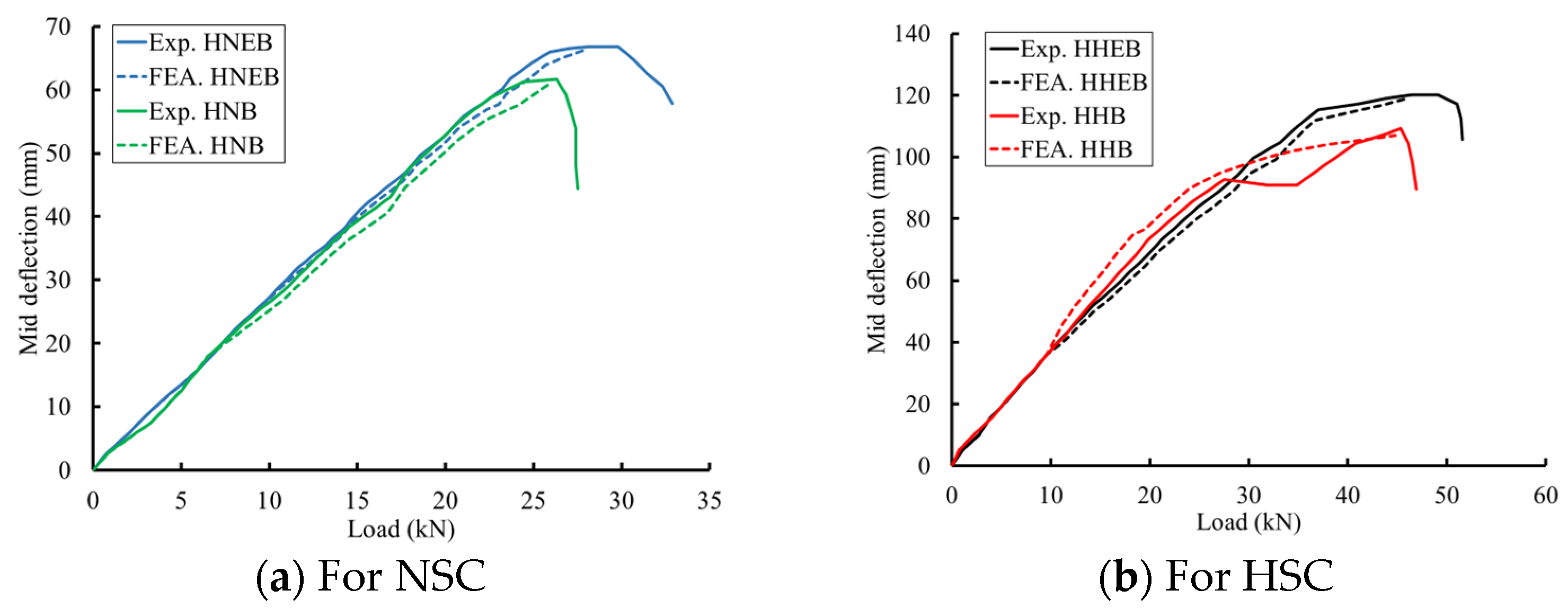
Numerous comparisons were conducted utilizing the experimental findings. Table 6 encompasses the load, deflection, and maximum load capability within this ratio. When subjected to the identical ultimate failure experimental load, the analysis conducted on the hybrid beam (HNB) resulted in a deflection measurement of 26.02 mm, whereas the experimental data revealed a deflection value of 26.32 mm. Figure 11 demonstrates a strong concurrence between the model FEA and experimental findings pertaining to the (load–deflection) curve across all composite beams.
Table 6.
Comparisons of the FE and experimental results.

Figure 11.
Experimental and FE comparisons in terms of the load–deflection curves.
Figure 12 illustrates a close concurrence between the FE and experimental deformations, suggesting that the Abaqus FE program accurately anticipated the flexural behavior of the examined specimens. Moreover, Table 7 provides additional comparisons in terms of the measured strains in the extreme fibers of the composite cross-sections under the ultimate failure load. These comparisons affirm that the developed FE models are capable of simulating the flexural behavior of the tested specimens.
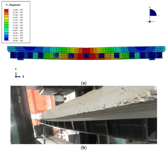
Figure 12.
Comparison between the FE and experimental deformation of beam HNB at the failure loading: (a) FE deformation and (b) experimental deformation.
Table 7.
Comparisons of the FE and experimental strains.
5. Conclusions
This research work experimentally and numerically investigates the use of GFRP I-beams in conjunction with concrete slabs to form composite beams. The experimental design incorporated GFRP I-beams connected compositely to concrete slabs. The concrete slabs are categorized into two groups: concrete slabs cast using NSC, and those cast using HSC. Various parameters like the type of concrete, the type of stiffeners bonded to the composite section (bolt–epoxy or bolt only), and the inclusion of corrugated metal sheets were used. Moreover, ABAQUS software was used to develop FE models to analyze the tested composite beams and provide a parametric study using the verified models.
- The strengthening of the shear webs of GFRP I-beams with GFRP T-section stiffeners resulted in an enhancement in the flexural and shear strength.
- The effect of the concrete compressive strength was vital, where the failure loads increased by 79.9% and 77.1% when the HSC was used instead of NSC for the cases of bolt–epoxy and bolts only, respectively.
- The composite beams that were reinforced using a combination of bolts and epoxy demonstrated significantly greater ultimate failure loads compared to the GFRP beams that were solely reinforced with bolts. The failure loads in the case of bolt–epoxy connection for the stiffeners were 8.2% and 10.0% higher than those in the case of bolts only when the concrete compressive strengths were 20.1 MPa and 52.3 MPa, respectively. The epoxy adhesive used in conjunction with mechanical connectors, specifically bolts, resulted in sufficient composite action and delayed shear failure within the web of the GFRP beam.
- For the specimens with bolt–epoxy connection, strain levels in the concrete slabs were consistently higher than the other specimens with bolts alone at the same loading level. The concrete slabs integrated with HSC registered strain levels that were 20.0% and 21.8% greater for bolt–epoxy and bolt-only connections, respectively, when compared to those using normal-strength concrete (NSC). This discrepancy can likely be credited to the enhanced composite interaction between the concrete slabs and the GFRP I-beams.
- Overall, the use of GFRP I-beams in conjunction with concrete warrants additional research and examination in order to establish a rational basis for the effective utilization of concrete and GFRP composites, and to investigate additional parameters.
Author Contributions
Data curation, M.I.A.; Formal analysis, M.I.A. and A.A.A.; Investigation, M.I.A. and A.E.-Z.; Methodology, A.A.A.; Resources, A.E.-Z.; Software, M.I.A.; Supervision, A.A.A. and A.E.-Z.; Validation, M.I.A.; Writing—original draft, M.I.A. and A.A.A.; Writing—review and editing, A.E.-Z. All authors have read and agreed to the published version of the manuscript.
Funding
This research received no external funding.
Data Availability Statement
Data are contained within the article.
Conflicts of Interest
The authors declare no conflicts of interest.
References
- Zhang, S.; Caprani, C. Mechanical properties of pultruded GFRP at intermediate strain rates. Compos. Struct. 2021, 278, 114699. [Google Scholar] [CrossRef]
- Liu, T.; Feng, P.; Lu, X.; Yang, J.; Wu, Y. Flexural behavior of novel hybrid multicell GFRP-concrete beam. Compos. Struct. 2020, 250, 112606. [Google Scholar] [CrossRef]
- Mahmood, E.M.; Allawi, A.A.; El-Zohairy, A. Flexural Performance of Encased Pultruded GFRP I-Beam with High Strength Concrete under Static Loading. Materials 2022, 15, 4519. [Google Scholar] [CrossRef] [PubMed]
- Vedernikov, A.; Gemi, L.; Madenci, E.; Özkılıç, Y.O.; Yazman, Ş.; Gusev, S.; Sulimov, A.; Bondareva, J.; Evlashin, S.; Konev, S.; et al. Effects of high pulling speeds on mechanical properties and morphology of pultruded GFRP composite flat laminates. Compos. Struct. 2022, 301, 116216. [Google Scholar] [CrossRef]
- Canning, L.; Hollaway, L.; Thorne, A. An investigation of the composite action of an FRP/concrete prismatic beam. Constr. Build. Mater. 1999, 13, 417–426. [Google Scholar] [CrossRef]
- Deskovic, N.; Meier, U.; Triantafillou, T.C. Innovative design of FRP combined with concrete: Long-term behavior. J. Struct. Eng. 1995, 121, 1079–1089. [Google Scholar] [CrossRef]
- Evbuomwan, N. Behaviour of FRP prismatic sections in composite action with concrete. In Proceedings of the International Conference on Fibre Reinforced Composites No7, Newcastle upon Tyne, UK, 15–17 April 1998; pp. 53–62. [Google Scholar]
- Liu, T.; Liu, X.; Feng, P. A comprehensive review on mechanical properties of pultruded FRP composites subjected to long-term environmental effects. Compos. Part B Eng. 2020, 191, 107958. [Google Scholar] [CrossRef]
- Zou, X.; Lin, H.; Feng, P.; Bao, Y.; Wang, J. A review on FRP-concrete hybrid sections for bridge applications. Compos. Struct. 2021, 262, 113336. [Google Scholar] [CrossRef]
- Ali, S.I.; Allawi, A.A. Effect of Web Stiffeners on The Flexural Behavior of Composite GFRP-Concrete Beam Under Impact Load. J. Eng. 2021, 27, 76–92. [Google Scholar] [CrossRef]
- Allawi, A.A.; Ali, S.I. Flexural behavior of composite GFRP pultruded I-section beams under static and impact loading. Civ. Eng. J. 2020, 6, 143–2158. [Google Scholar] [CrossRef]
- Gemi, L.; Madenci, E.; Özkılıç, Y.O. Experimental, analytical and numerical investigation of pultruded GFRP composite beams infilled with hybrid FRP reinforced concrete. Eng. Struct. 2021, 244, 112790. [Google Scholar] [CrossRef]
- Hadi, M.N.S.; Youssef, J. Experimental investigation of GFRP-reinforced and GFRP-encased square concrete specimens under axial and eccentric load, and four-point bending test. Compos. Constr. 2016, 20, 04016020. [Google Scholar] [CrossRef]
- Evbuomwan, N.F.O. Flexural behaviour of GFRP prismatic beams in composite action with concrete. In Research and Applications in Structural Engineering, Mechanics and Computation; Taylor and Francis Group: London, UK, 2013; Chapter 267. [Google Scholar] [CrossRef]
- Hadi, M.N.S.; Yuan, J.S. Experimental investigation of composite beams reinforced with GFRP I-beam and steel bars. Constr. Build. Mater. 2017, 144, 462–474. [Google Scholar] [CrossRef]
- Xue, W.; Zhang, S. Experimental study on shear connectors of FRP concrete composite beams. J. Highw. Transp. Res. Dev. 2014, 10, 207–210. [Google Scholar]
- Neagoe, C.A.; Gil, L.; Pérez, M.A. Experimental study of GFRP-concrete hybrid beams with low degree of shear connection. Constr. Build. Mater. 2015, 101, 141–151. [Google Scholar] [CrossRef]
- Correia, J.R.; Gomes, M.M.; Pires, J.M.; Branco, F.A. Mechanical behaviour of pultruded glass fibre reinforced polymer composites at elevated temperature: Experiments and model assessment. Compos. Struct. 2013, 98, 303–313. [Google Scholar] [CrossRef]
- Nkosi, G.M. A Reliability Based Comparison of Eurocode 3 & SANS 10162-1. Master’s Thesis, University of Johannesburg, Johannesburg, South Africa, 2020. [Google Scholar]
- ASTM D695; Standard Test Method for Compressive Properties of Rigid Plastics. ASTM International: West Conshohocken, PA, USA, 2015.
- ISO 527-1; Plastics—Determination of Tensile Properties—Part 1: General Principles. ISO: Geneva, Switzerland, 2019.
- Karayannis, C.G.; Kosmidou, P.-M.K.; Chalioris, C.E. Reinforced Concrete Beams with Carbon-Fiber-Reinforced Polymer Bars—Experimental Study. Fibers 2018, 6, 99. [Google Scholar] [CrossRef]
- BS 1881-124:2015; Testing Concrete. Methods for Analysis of Hardened Concrete. British Standards Institution: London, UK, 2015.
- Abaqus. Abaqus 6.2: Computer Software for Finite Element Analysis; Dassault Systems Simulia: Johnston, RI, USA, 2019. [Google Scholar]
- Ibrahim, T.H.; Allawi, A.A.; El-Zohairy, A. Experimental and FE analysis of composite RC beams with encased pultruded GFRP I-beam under static loads. Adv. Struct. Eng. 2023, 26, 516–532. [Google Scholar] [CrossRef]
- Hafezolghorani, M.; Hejazi, F.; Vaghei, R.; Jaafar, M.S.B.; Karimzade, K. Simplified Damage Plasticity Model for Concrete. Struct. Eng. Int. 2018, 27, 68–78. [Google Scholar] [CrossRef]
- Eurocode 2: Design of Concrete Structures-Part 1-1: General Rules and Rules for Buildings; British Standards Institution: London, UK, 2004.
- Kent, D.C.; Park, R. Flexural members with confined concrete. J. Struct. Div. 1971, 97, 1969–1990. [Google Scholar] [CrossRef]
- Park, R. Reinforced Concrete Structures; John Wiley & Sons: New York, NY, USA, 1975. [Google Scholar]
- Hashin, Z. Fatigue failure criteria for unidirectional fiber composites. J. Appl. Mech. 1980, 47, 329–334. [Google Scholar] [CrossRef]
- Barbero, E.; Cosso, F.; Roman, R.; Weadon, T. Determination of material parameters for Abaqus progressive damage analysis of E-glass epoxy laminates. Compos. Part B Eng. 2013, 46, 211–220. [Google Scholar] [CrossRef]
- Barbero, E.J. Finite Element Analysis of Composite Materials Using Abaqus®; CRC Press: Boca Raton, FL, USA, 2023. [Google Scholar]
- Ibrahim, T.H.; Allawi, A.A.; El-Zohairy, A. Impact Behavior of Composite Reinforced Concrete Beams with Pultruded I-GFRP Beam. Materials 2022, 15, 441. [Google Scholar] [CrossRef] [PubMed]


Disclaimer/Publisher’s Note: The statements, opinions and data contained in all publications are solely those of the individual author(s) and contributor(s) and not of MDPI and/or the editor(s). MDPI and/or the editor(s) disclaim responsibility for any injury to people or property resulting from any ideas, methods, instructions or products referred to in the content. |
© 2024 by the authors. Licensee MDPI, Basel, Switzerland. This article is an open access article distributed under the terms and conditions of the Creative Commons Attribution (CC BY) license (https://creativecommons.org/licenses/by/4.0/).