Abstract
The need for concrete with ‘super’ strength and ‘super’ ductility for greater sustainability has been answered by the existence of ultra-high-performance concrete (UHPC) and ultra-high-performance fiber-reinforced concrete (UHPFRC). Over the last decades, UHPFRC has been implemented in actual concrete structures, as well as used to retrofit structural elements, including columns. However, the use of UHPC and UHPFRC confinement to strengthen normal concrete columns is still limited. Therefore, this research aims to investigate the advanced performance of columns using UHPC and UHPFRC confinement in the context of the strength and ductility of such columns, such as load capacity, stress–strain behavior, and the crack pattern in the failure mode. This research is an advanced study of several investigations previously carried out by other authors on the characteristics of UHPC and UHPFRC, as well as columns confined by UHPC and UHPFRC. The methods used in this research are experimental and analytical. The experimental results were compared to analytical calculations for validation. This research produced 12 short-column specimens confined by UHPC (CF0 series) and UHPFRC (CF1 and CF2 series) that contained 0%, 1%, and 2% fiber and were also tested for axial loading and various eccentricities as follows: e = 0, 35, and 70 mm. The results found that the normal strength concrete (NSC) columns confined by UHPC and UHPFRC could sustain a higher maximum load and stress, and also sustain greater vertical deformation and strain compared to the control specimens. It was noted that specimen CF2-35 had the highest load capacity, vertical deformation, maximum stress, and maximum vertical strain compared to specimen C-0 (control column with no confinement). The specimen CF2-35 (column confined by UHPC with a 2% fiber volume with an eccentricity of 35 mm) also exhibited a ductile failure mode and very minor cracks. It was also found that 75% of the specimens had 0–39% errors and 25% had 0–13% errors. The research proved that the addition of a volume of 2% fiber to the UHPFRC minimizes the crack of the failure mode and prevents confinement spalling of the column. This research has led to the conclusion that UHPC and UHPFRC confinements will increase the strength and ductility of columns.
1. Introduction
Ultra-high-performance concrete (UHPC) was developed in the 1970s to cope with the limitations of ordinary reinforced concrete. This concrete invention successfully promotes superior strength, mechanical properties, durability, and long-term stability, and it is known as an innovative cement-based composite material [1,2]. The implementation of UHPC also provides viable and sustainable concrete structures with ultra-high-strength properties, improved fatigue behavior, very low porosity, and excellent resistance against aggressive environments [3]. However, the application of UHPC in construction has limitations, such as a higher initial cost, lack of contractors with experience, and absence of widely accepted design provisions [4].
Since there has been an urgent need for concrete with ‘super’ strength and ‘super’ ductility for greater sustainability, ultra-high-performance fiber-reinforced concrete (UHPFRC) was developed in 1972 with the production of ultra-high-strength cement paste [5,6,7]. In the 1980s, there was a progressive development of UHPFRC, for example, the invention of the densified small particle (DSP) and macro defect-free (MDF) [8,9] flowable cement–mortar composite pastes [10], and the reactive powder concrete (RPC) [11].
There are several studies on columns confined by UHPC or UHPFRC. A study of circular steel tubes confined by UHPC columns under uniaxial compression was reported in [12]. The 2% fiber volume of the UHPFRC did not result in any significant change to the strength. However, the addition of steel fibers to the UHPFRC enhanced the ductility in the post-peak stage of the load–deformation. Another study reported experimental and analytical research on UHPC columns confined by high-strength transverse reinforcement under eccentric compression [13]. The investigation had several parameters, such as deformation capacity, peak load, and residual load carrying capacity of the column under eccentric loading, which were better than those of the reference specimens. In the context of column retrofitting, a study on the strengthening of several columns using a UHPFRC ‘jacket’ (i.e., confinement) was reported in [14]. Carbon fiber-reinforced polymer (CFRP) ropes were used for circular columns with various layers and spacings that were preloaded at different levels [15]. Several studies have been carried out to investigate the performance of short columns confined by fibrous ‘jackets’ [16], UPHFRC tubes [17], and FRPs [18].
The innovation of UHPC and UHPFRC is still currently needed in the construction field. Over the last decades, UHPFRC has been implemented in actual concrete structures, as well as used to retrofit structural elements [19], including columns. However, the use of UHPC and UHPFRC confinement to strengthen normal concrete columns is still limited, especially in the context of the strength and ductility of columns, such as load capacity, stress–strain behavior, and crack pattern at the failure mode.
It should be noted that this study is an advanced study of previous research by other authors [20,21,22,23,24,25] on UHPC and UHPFRC characteristics, as well as columns confined by UHPC and UHPFRC. The first studies by such authors investigated the mechanical properties of UHPC and UHPFRC (i.e., tensile and compressive strength) as reported in [20,22,24,25]. The next studies conducted were on normal strength columns confined by UHPC [21,23]. The modeling of the columns confined by UHPC was conducted using the finite element program as a numerical approach to validate the experimental results [21]. The initial simple analyses of several columns confined by UHPC and UHPFRC were reported in [23]. In this advanced study, a specimen series of NSC (normal strength concrete) columns confined by UHPC and UHPFRC were analyzed in depth on its load–deformation behavior, stress–strain performance, crack patterns, and failure mode and ductility. It also conducted analytical calculations as a comparison for the experimental results. This advanced study of columns confined by UHPC and UHPFRC was conducted to meet the conclusion and achieve the purpose of the research.
2. Materials and Methods
This research was conducted using experimental and analytical methods. Numerical modeling of the columns’ behavior was previously carried out and reported by other authors using a 3D nonlinear finite element analysis (FEA) program to run a nonlinear analysis of the behavior of columns confined by UHPC [21]; hence, a nonlinear analysis of the behavior of columns was not conducted in this study. The experimental results are compared to the analytical calculations using the equations derived in the studies in [26,27,28,29] to meet the conclusions.
2.1. Materials
This research produced 12 short-column specimens that were tested for axial loading. Those columns were subjected to 2 loading configurations as concentric loading (with e = 0 mm) and eccentric loadings (with e = 35 mm and e = 70 mm). Those short columns are used in this research because they are designed to avoid additional bending moments due to the second order of the P-Δ Effect [30].
All column specimens made of NSC (normal strength concrete) were confined by UHPC or UHPFRC except the control specimens. The NSC columns were C30/37 class and had dimensions of 200 mm × 200 mm, a height of 750 mm, and concrete cover thickness of 25 mm. The stirrups of CSC columns used an ∅8 mm steel bar with a pitch of 100 mm (outside lap section) and 50 mm (in lap section). The experiment was conducted at the Official Material Testing Institute for Construction Industry (Amtliche Materialprüfanstalt für das Bauwesen, AMPA) of the University of Kassel. The column specimen’s description is described in Table 1, while the geometry, dimension, and cross-section of column specimens are presented in Figure 1.

Table 1.
Column specimen’s description.
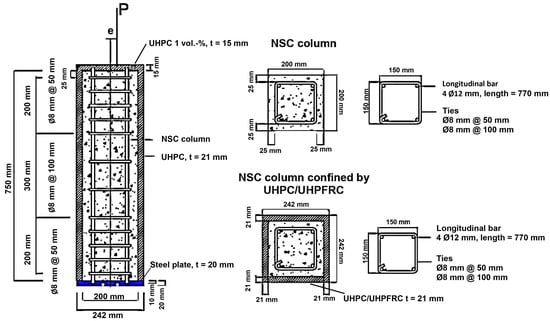
Figure 1.
Geometry, dimension, and cross-section of column specimens [21,23].
In this study, the 3 NSC columns without confinement became the control specimens, while the other 9 columns were confined by UHPC and UHPFRC with a thickness of 21 mm and fibers (0%, 1%, and 2%). Steel fibers, which were golden-colored fibers (Figure 2), were added into the UHPC and UHPFRC mixtures with a length of 10 mm and diameter of 0.2 mm. The NSC columns used 4Ø12 mm deformed steel bars BSt500S(A) as longitudinal reinforcements, and Ø8 mm as ties with a pitch of 100 mm (outside lap section) and 50 mm (in lap section). Sandblasting was added to make a monolithic surface interface between the NSC column and UHPC and UHPFRC confinements. The UHPC and UHPFRC mixture formula was M3Q_210 with designed compressive strength (fcku) of about 200 MPa at the age of 28 days.
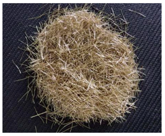
Figure 2.
Golden-colored steel fiber was used in the experiment [22].
Several tests were conducted to obtain the properties of NSC, UHPC/UHPFRC, fiber, and steel bars, which are presented in Table 2.

Table 2.
The result of the properties test of NSC, UHPC/UHPFRC, fiber, and steel bar.
2.2. Experiment Setup
The experiment and loading tests were conducted in the Structural Materials and Engineering Laboratories of the Civil and Environmental Engineering Department at the University of Kassel. A hydraulic testing machine with a maximum capacity limit of 6.3 MN was used, as presented in Figure 3. During the loading test, a velocity of 0.01 mm/s was applied with a frequency of 5 values per second.
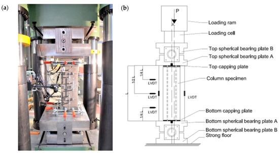
Figure 3.
Experiment setup for loading test for columns. (a) Loading setup for column specimen and (b) detail of loading setup [21].
2.3. Methods
2.3.1. Modeling of UHPC/UHPFRC Compressive Strength
A model of the UHPC section capacity in a column’s section was proposed by this study and also the previous ones [21,31] based on the development of 4 standards and guidelines [26,27,28,29] such as the standard developed by VSL (Aust) Pty Ltd. which provided guidelines for the design of prestressed concrete beams using the Reactive Powder Concrete known as DUCTAL, also consistent with the limit states design philosophy of AS3600-1994 [26]; the AFGC/SETRA working group on Ultra-High Performance Fibre-Reinforced Concrete chaired first by Benoît Lecinq (when he was at SETRA), then by Jacques Resplendino (CETE de Lyon) [27]; the Recommendations for Design and Construction of Ultra High Strength Fiber Reinforced Concrete Structures, JSCE guidelines for concrete; the Subcommittee on Research of Ultra High Strength Fiber Reinforced Concrete; Japan Society of Civil Engineers (JSCE) [28]; and also Sachstandsbericht Ultrahochfester Beton—Betontechnik und Bemessung [29]. In this study, the model calculated the capacity of UHPC in a column’s section under axial loading. The actual compression loading under axial loading is described by Equations (1) and (2).
where:
= actual compression loading of UHPC column/section;
= actual compression loading of UHPFRC column/section;
fcud,0% = design value of UHPC compressive strength (UHPC = 0% fiber);
fcud,i% = design value of UHPFRC compressive strength (UHPFRC = i% fiber);
χ = safety factor (0.85–0.90) based on [31];
fctfd,i% = design value of maximum tensile stress;
Afu,i% = total cross section of the fiber.
2.3.2. Stress–Strain Relationship of UHPC/UHPFRC
The stress–strain curve of the Ultimate Limit State (ULS) design that is based on DIN 1045-1 can be explained by Equation (3) as follows:
where:
εc = strain at maximum stress;
εc2u = ultimate strain.
3. Results
3.1. Load–Deformation
Figure 4 describes the relationship of the load (P) and vertical deformation (ΔLv) of all column specimen series of C, CF0, CF1, and CF2. For the C series specimens presented in Figure 4a, the highest load capacity was achieved by C-0 with P = 919.30 kN and ΔLv = 2.08 mm, followed by C-35 with P = 740.63 kN and ΔLv = 1.96 mm, and followed by C-70 with P = 471.24 kN and ΔLv = 2.38 mm.
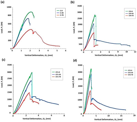
Figure 4.
Load–deformation relationships of columns subjected to axial loadings with eccentricities of e = 0, 35, and e = 70 mm of the series of specimens as follows: (a) Load–deformation relationships of C series, (b) Load–deformation relationships of CF0 series, (c) Load–deformation relationships of CF1 series, and (d) Load–deformation relationships of CF2 series.
The result of the axial loading for the CF0 series described in Figure 4b of the specimens can be explained as follows: It was found that a maximum load capacity was achieved by CF0-0 with P = 2803.00 kN and ΔLv = 2.94 mm, followed by CF0-35 with P = 2106.97 kN and ΔLv = 2.42 mm, and followed by CF0-70 with P = 1399.10 kN and ΔLv = 2.45 mm.
It was also recorded and shown in Figure 4c that the specimen series of CF1 performed better than the specimen series of C and CF-0. This study also noted that CF1-0 achieved the maximum load capacity of P = 2962.51 kN and ΔLv = 2.96 mm, followed by CF1-35 with P = 2368.30 kN and ΔLv = 2.85 mm, followed by CF1-70 with P = 1510.49 kN and ΔLv = 2.72 mm.
In general, the highest load capacity of all specimens was achieved by the specimen series of CF2 as presented in Figure 4d. The maximum load capacity was achieved by CF2-0 with P = 3246.26 kN and ΔLv = 3.09 mm, followed by CF2-35 with P = 2835.76 kN and ΔLv = 3.14 mm, and also followed by CF2-70 with P = 1656.14 kN and ΔLv = 2.76 mm.
It was observed that the specimen series of CF1 and CF2 performed a specific phenomenon as described in Figure 4, that after the peak load was achieved, there was a ‘tail’ of the curve that indicated post-peak deformation caused by the ductility of the columns.
3.2. Stress–Strain Behavior
This study observed the stress–strain behavior of the column specimens of all series as presented in Figure 5. It was found that the stress (σ) and vertical strain (δv) relationship was similar to the load–deformation curve in Figure 4.
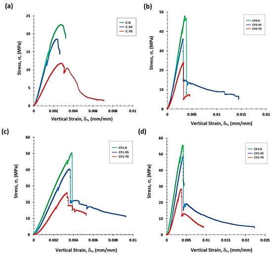
Figure 5.
Stress–strain behavior of columns subjected to axial loadings with eccentricities of e = 0, 35, and e = 70 mm of the series of specimens as follows: (a) Stress–strain behavior of C series, (b) Stress–strain behavior of CF0 series, (c) Stress–strain behavior of CF1 series, and (d) Stress–strain behavior of CF2 series.
It was found from the experiment that among the specimens of C series as described by Figure 5a, C-0 achieved the highest value of σ = 22.98 MPa and δv = 0.0028 mm/mm, followed by C-35 with σ = 18.52 MPa and δv = 0.0026 mm/mm, and C-70 with σ = 11.78 MPa and δv = 0.0032 mm/mm. The experiment found the longer ‘tail’ of vertical strain achieved by C-0.
Figure 5b described the stress–vertical strain curve of the specimen series of CF0. The highest stress was achieved by CF0-0 with σ = 47.86 MPa and δv = 0.0036 mm/mm, followed by CF0-35 with σ = 35.98 MPa and δv = 0.0032 mm/mm. The lowest stress in the specimen series of CF0 was achieved by CF0-70 with σ = 23.89 MPa and δv = 0.0045 mm/mm. In this series of CF0, CF0-35 was observed to have the longest ‘tail’ of the vertical strain, followed by CF0-70.
The stress–vertical strain curve of the specimens of the CF1 series is described in Figure 5c. It was recorded that CF1-0 achieved the highest value of stress and strain with σ = 50.59 MPa and δv = 0.0039 mm/mm, followed by CF1-35 with σ = 40.39 MPa and δv = 0.0038 mm/mm. It was also found that the lowest value of stress and strain was achieved by CF1-70 with σ = 25.79 MPa and δv = 0.0036 mm/mm. The longest ‘tail’ of vertical strain was achieved by CF1-35, followed by CF1-70.
The specimens of the CF2 series stress–vertical strain curve are shown in Figure 5d. It was recorded that CF2-0 achieved the highest stress and strain with σ = 55.43 MPa and δv = 0.0041 mm/mm, followed by CF2-35 with σ = 48.40 MPa and δv = 0.0042 mm/mm. The experiment results also noted that CF2-70 achieved the lowest stress and strain with σ = 28.28 MPa and δv = 0.0037 mm/mm. A very long ‘tail’ of vertical strain was achieved by CF2-35, followed by CF2-70.
The analytical results using Equations (1)–(3) are presented in Table 3. The same phenomenon was experienced by the analytical results that were also performed by the experimental results described in Figure 3 and Figure 4 as follows. It was found that the addition of fiber into the mixture of confinements increased the load capacity and stress as shown by the specimen series of CF0 (0% fiber in confinement), CF1 (1% fiber in confinement), CF2 and (2% fiber in confinement). This result confirmed the studies of [12,13,14] that the addition of fiber increases the strength and ductility of the column. The eccentricities of the columns also gave significant influence that the greater the eccentricity that existed, the lower the load capacity performed.

Table 3.
Analytical results of Pmax and σmax of all specimen series.
3.3. Crack Pattern
The experiment has shown that all specimens obtained crack patterns after the loading e as described obviously by the specimens with e = 70 mm in Figure 6. It was observed that specimen series C experienced fewer cracks compared to specimen series CF1 and CF2. However, there was spalling of concrete in the corner of one side of the column. The series of CF0 was observed being crushed significantly and the confinement spalling out of the main columns when the specimen was failed. The specimen series of CF1 and CF2 experienced ductile failure and the cracks only happened on one side, in the center of the side. There was a very loud noise when the CF0 had a sudden failure.
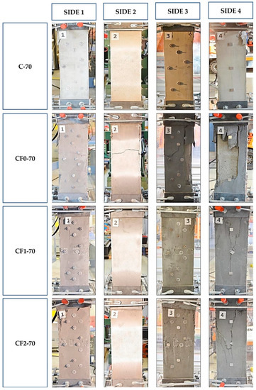
Figure 6.
Crack pattern of the specimens with an eccentricity of 70 mm.
4. Discussion
This study observes, in general, that the experimental results have higher values of load and stress compared to the analytical results, as described by Figure 7 and Figure 8. However, several analytical results achieved slightly higher values of maximum loads and stresses of C-0 (control specimen as the baseline), C-70, CF0-70, CF1-70, and CF2-70. It should be emphasized that the bigger the percentage of fiber added to the confinement, the higher the load capacity and stress of the specimen. The highest performance of specimens was achieved by the zero eccentricity of the specimens.
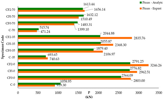
Figure 7.
Experimental and analytical results of load of all specimen series.
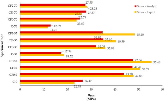
Figure 8.
Experimental and analytical results of the stress of all specimen series.
A comparison to another study of [17] will give a good insight as presented in Table 4. The rectangular column specimen series of both studies to be discussed have the same fiber volume for the UHPFRC confinement as 2%, and a similar ratio of width and height of the column. Different loading types were applied; eccentric loading was applied to the series of CF2 of the current study, and concentric loading was applied to the series of HCC2 [17].

Table 4.
Description of the specimen of column confined by UHPHFRC from the current study compared to the study of Wu et al. [17].
Figure 9 shows that the crack pattern of the current study was very minor that appeared on the corner of Face 1 of the column, and the upper middle of Face 4 of the column. The specimen’s series of the study of [17] showed that the vertical cracks near the column borders appeared in most faces (Faces 1, 3, and 4). It seemed that the bond between the column core and the UHPFRC was not good enough. In general, the 2% fiber volume prevented catastrophic failure in both studies, but an optimum fiber volume belongs to the current study compared to [17] since the crack pattern at failure mode was found to have a minor crack. Hence, the series of the CF2 of column confined by UHPFRC in the current study achieved better ductility compared to [17].

Figure 9.
Crack pattern at failure mode of column confined by UHPFRC, (a) current study, and (b) Wu et al. [17].
The results of this study found that the optimum parameter values were achieved by CF2-35 because it has a load capacity of 3.8 times compared to the control specimen (C-0), a vertical deformation of 1.61 times compared to C-0, a maximum stress of 2.61 times compared to C-0, and a maximum vertical strain of 1.60 times compared to C-0. Compared to the study of [17], the current study that performed the peak load of CF2-0 was 3.53 times to the control as presented by Table 5, with P = 3246.26 kN and ΔLv = 3.09 mm, while in the study of [17], the peak load of HCC2 was 1.11 times to the control, with P = 3729 kN and δu = 4 mm. Hence, this current study performs better column ductility compared to the study of [17].

Table 5.
The ratio of specimens to control of several parameters.
For a better analysis, the errors of the Pmax experimental and analytical results described in Table 3 were analyzed by Box Plot, as presented in Figure 10. It is found that 75% of the specimens have a higher Pmax compared to the control (0–39% error), and only 25% have a lower Pmax compared to the control (0–13% error). Hence, the maximum error of 39% was accepted and confirmed as an actual phenomenon because it was the result of the loading test.

Figure 10.
The errors of Pmax between experimental and analytical results.
5. Conclusions
This study investigates several columns confined by UHPC and UHPFRC under axial loading with various eccentricities. The results show that the NSC columns confined by UHPC and UHPFRC could sustain higher maximum load and stress as well as sustain larger vertical deformation and strain compared to the control specimens. The best performance was achieved by CF2-35 because it has the highest load capacity, vertical deformation, maximum stress, and also maximum vertical strain, compared to C-0. The specimen CF2-35 also performed a ductile failure mode and very minor cracks. It was also found that 75% of specimens have a 0–39% error, and 25% have a 0–13% error.
The results of this research found that the addition of 2% fiber volume to the UHPFRC minimized the crack at failure mode and prevented the confinement spalling from the column. This research meets the conclusions that the UHPC and UHPFRC confinements will increase the strength and ductility of the column.
Author Contributions
Conceptualization, R.M.I.R.S. and Y.K.; methodology, R.M.I.R.S. and Y.K.; validation, R.M.I.R.S.; formal analysis, R.M.I.R.S. and Y.K.; investigation, Y.K.; resources, R.M.I.R.S. and Y.K.; data curation, Y.K.; writing—original draft preparation, R.M.I.R.S. and Y.K.; writing—review and editing, R.M.I.R.S.; visualization, Y.K.; supervision, Y.K.; project administration, Y.K.; funding acquisition, R.M.I.R.S. All authors have read and agreed to the published version of the manuscript.
Funding
This research was funded by the Ministry of Education, Culture, Research and Technology, Republic of Indonesia; the Directorate General of Higher Education; and the Directorate of Research, Technology, and Community Service, by the Applied Research Grant 2021–2022, Contract No. 312/E4.l/AK.04.PT/2021 and No. 072/E5/PG.02.00.PT/2022. The APC was funded by the Ministry of Education, Culture, Research and Technology, Republic of Indonesia; the Directorate General of Higher Education; and the Directorate of Research, Technology, and Community Service, by the Applied Research Grant Applied 2022, Contract No. 072/E5/PG.02.00.PT/2022.
Data Availability Statement
Not applicable.
Acknowledgments
The authors acknowledge the support and financial assistance of the Ministry of Education, Culture, Research and Technology, Republic of Indonesia; the Directorate General of Higher Education; and the Directorate of Research, Technology, and Community Service; the University of Kassel, Concrete Structures Department (Institute of Structural Engineering, IKI); and Semarang State University.
Conflicts of Interest
The authors declare no conflict of interest. The funders had no role in the design of the study; in the collection, analyses, or interpretation of data; in the writing of the manuscript; or in the decision to publish the results.
References
- Aziz, O.Q.; Ahmed, G.H. Mechanical Properties of Ultra High Performance Concrete (UHPC); ACI Special Publicatio; American Concrete Institute: Farmington Hills, MI, USA, 2012; pp. 331–346. [Google Scholar]
- Akeed, M.H.; Qaidi, S.; Ahmed, H.U.; Faraj, R.H.; Mohammed, A.S.; Emad, W.; Tayeh, B.A.; Azevedo, A.R.G. Ultra-High-Performance Fiber-Reinforced Concrete. Part II: Hydration and Microstructure. Case Stud. Constr. Mater. 2022, 17, e01289. [Google Scholar] [CrossRef]
- El-khoriby, R.S.; Taher, S.E.; Ghazy, M.F.; Abd-elaty, M.A. How Practical Is Ultra High Performance Concrete for Construction Projects How Practical Is Ultra High Performance Concrete For. In Proceedings of the International Conference on Advances in Structural and Geotechnical Engineering (ICASGE’19), Tanta, Egypt, 25–28 March 2019; Volume 3, pp. 93–137. [Google Scholar]
- Abbas, S.; Nehdi, M.L.; Saleem, M.A. Ultra-High Performance Concrete: Mechanical Performance, Durability, Sustainability and Implementation Challenges. Int. J. Concr. Struct. Mater. 2016, 10, 271–295. [Google Scholar] [CrossRef]
- Roy, D.M.; Gouda, G.R.; Bobrowsky, A. Very High Strength Cement Pastes Prepared by Hot Pressing and Other High Pressure Techniques. Cem. Concr. Res. 1972, 2, 349–366. [Google Scholar] [CrossRef]
- Yudenfreund, M.; Odler, I.; Brunauer, S. Hardened Portland Cement Pastes of Low Porosity I. Materials and Experimental Methods. Cem. Concr. Res. 1972, 2, 313–330. [Google Scholar] [CrossRef]
- Biswas, R.K.; Bin Ahmed, F.; Haque, M.E.; Provasha, A.A.; Hasan, Z.; Hayat, F.; Sen, D. Effects of Steel Fiber Percentage and Aspect Ratios on Fresh and Harden Properties of Ultra-High Performance Fiber Reinforced Concrete. Appl. Mech. 2021, 2, 501–515. [Google Scholar] [CrossRef]
- Alford, N.M.; Birchall, J.D. The Properties and Potential Applications of Macro-Defect-Free Cement. MRS Proc. 1984, 42, 265–276. [Google Scholar] [CrossRef]
- Bache, H.H. Introduction to Compact Reinforced Composite; Nordic Concrete Federation: Aalborg Portland, Denmark, 1987; pp. 19–33. [Google Scholar]
- de Larrard, F.; Sedran, T. Optimization of Ultra-High-Performance Concrete by the Use of a Packing Model. Cem. Concr. Res. 1994, 24, 997–1009. [Google Scholar] [CrossRef]
- Richard, P.; Cheyrezy, M. Composition of Reactive Powder Concretes. Cem. Concr. Res. 1995, 25, 1501–1511. [Google Scholar] [CrossRef]
- Hoang, A.L.; Fehling, E.; Lai, B.; Thai, D.-K.; Van Chau, N. Experimental Study on Structural Performance of UHPC and UHPFRC Columns Confined with Steel Tube. Eng. Struct. 2019, 187, 457–477. [Google Scholar] [CrossRef]
- Ding, Y.; Zeng, B.; Zhou, Z.; Wei, Y.; Huang, Y. Behavior of UHPC Columns Confined by High-Strength Transverse Reinforcement under Eccentric Compression. J. Build. Eng. 2023, 70, 106352. [Google Scholar] [CrossRef]
- Koo, I.-Y.; Hong, S.-G. Strengthening RC Columns with Ultra High Performance Concrete. In Proceedings of the 2016 Structures Congress, Jeju Island, Korea, 28 August–1 September 2016. [Google Scholar]
- Ashteyat, A.M.; Obaidat, A.T.; Obaidat, Y.T.; Abdel-Jaber, M.; Al-Tarawneh, D. The Behavior of Strengthened and Repaired RC Columns with (CFRP) Rope under Different Preloading Levels. Eur. J. Environ. Civ. Eng. 2023, 1–25. [Google Scholar] [CrossRef]
- Mhuder, W.J.; Chassib, S.M. Strengthening of RC Circular Short Columns with Fibrous Jacket. IOP Conf. Ser. Mater. Sci. Eng. 2020, 928, 022075. [Google Scholar] [CrossRef]
- Wu, X.; Kang, T.H.K.; Mpalla, I.B.; Kim, C.S. Axial Load Testing of Hybrid Concrete Columns Consisting of UHPFRC Tube and Normal-Strength Concrete Core. Int. J. Concr. Struct. Mater. 2018, 12, 43. [Google Scholar] [CrossRef]
- Chauhan, M.A.; Agha, S.; Rattan, I. Strengthening of Reinforced Concrete Beam Using FRP. Int. J. Eng. Res. Technol. 2021, 10, 416–436. [Google Scholar]
- Luu, X.-B.; Kim, S.-K. Finite Element Modeling of Interface Behavior between Normal Concrete and Ultra-High Performance Fiber-Reinforced Concrete. Buildings 2023, 13, 950. [Google Scholar] [CrossRef]
- Kusumawardaningsih, Y.; Fehling, E.; Ismail, M.; Aboubakr, A.A.M. Tensile Strength Behavior of UHPC and UHPFRC. Procedia Eng. 2015, 125, 1081–1086. [Google Scholar] [CrossRef]
- Kusumawardaningsih, Y.; Fehling, E. Behavior of Ultra High Perfoemance Concrete (UHPC) Confinement on Normal Strength Concrete (NSC) Column. In Proceedings of the Deutscher Ausschuss fur Stahlbeton- 53 Dafstb Forschungskolloqium, Kassel, Germany, 9–10 October 2012; Intitut fur Konstruktiven Ingenieurbau der Universitat Kassel: Kassel, Germany, 2012; pp. 165–170. [Google Scholar]
- Kusumawardaningsih, Y.; Susilorini, R.M.I.R.; Aboubakr, A. Properties of Ultra High Performance Concrete. In Proceedings of the International Conference on Concrete and Infrastructure 2015, Semarang, Indonesia, 28–30 October 2015; pp. 44–49. [Google Scholar]
- Kusumawardaningsih, Y.; Fehling, E. Behavior of RC Columns Confined with UHPC. In Proceedings of the 5th International Symposium on Ultra-high Performance Concrete and High Performance Construction Materials, Kassel, Germany, 11–13 March 2020; Middendorf, B., Fehling, E., Wetzel, A., Eds.; Kassel University Press: Kassel, Germany, 2020; pp. 13–16. [Google Scholar]
- Kusumawardaningsih, Y.; Fehling, E.; Hardjasaputra, H.; Al-Ani, Y.; Aboubakr, A.A.M. Axial Tensile Strengths of UHPC and UHPFRC. IOP Conf. Ser. Mater. Sci. Eng. 2019, 615, 3–12. [Google Scholar] [CrossRef]
- Kusumawardaningsih, Y.; Fehling, E.; Ismail, M. UHPC Compressive Strength Test Specimens: Cylinder or Cube? Procedia Eng. 2015, 125, 1076–1080. [Google Scholar] [CrossRef]
- Gowripalan, N.; Gilbert, I.R. Design Guidelines for Ductal Prestressed Design Guidelines for Ductal Prestressed Concrete Beams N Gowripalan and R I Gilbert the University of New South Wales; VSL (Aust) Pty Ltd.: Sidney, Australia, 2000. [Google Scholar]
- Janvier. Bétons Fibrés à Ultra-Hautes Performances-Recommandations Provisoires; AFGC: Griffith, Australia, 2002; ISBN 9780870316418. [Google Scholar]
- Niwa, J.; Gakkai, D. Recommendations for Design and Construction of Ultra High Strength Fiber Reinforced Concrete Structures (Draft); JSCE Guidelines for Concrete; Subcommittee on Research of Ultra High Strength Fiber Reinforced Concrete, Japan Society of Civil Engineers (JSCE): Tokyo, Japan, 2006; ISBN 9784810605570. [Google Scholar]
- Schmidt, P.M.; Bunje, D.K.; Dehn, J.F.; Greiner, S.; Horvath, J.; Kleen, D.E.; Müller, C.; Teutsch, M.; Tue, N.V. Sachstandsbericht-Ultrahochfester Beton; Deutscher Ausschuss für Stahlbeton DAfStb: Berlin, Germany; Wien, Austria; Zürich, Switzerland, 2008. [Google Scholar]
- European Committee for Standardization. Eurocode 2: Design of Concrete Structures—Part 1-1: General Rules and Rules for Buildings—EN 1992-1-1; European Committee for Standardization: Brussel, Belgium, 2004. [Google Scholar]
- Leutbecher, T.; Fehling, E. A Simple Design Approach for UHPFRC in Bending. In Proceedings of the RILEM-fib-AFGC International Symposium on Ultra-High Performance Fibre-Reinforced Concrete, Marseille, France, 1–3 October 2013; pp. 509–518. [Google Scholar]
Disclaimer/Publisher’s Note: The statements, opinions and data contained in all publications are solely those of the individual author(s) and contributor(s) and not of MDPI and/or the editor(s). MDPI and/or the editor(s) disclaim responsibility for any injury to people or property resulting from any ideas, methods, instructions or products referred to in the content. |
© 2023 by the authors. Licensee MDPI, Basel, Switzerland. This article is an open access article distributed under the terms and conditions of the Creative Commons Attribution (CC BY) license (https://creativecommons.org/licenses/by/4.0/).