Article

Investigation of the Influence of Hexabenzocoronene in Polyacrylonitrile-Based Precursors for Carbon Fibers

1
Institute of Lightweight Engineering and Polymer Technology, Technische Universität Dresden, Holbeinstr. 3, 01307 Dresden, Germany
2
Research Center Carbon Fibers Saxony, Technische Universität Dresden, Holbeinstr. 3, 01307 Dresden, Germany
3
Carbon Composite Materials Research Center, Korea Institute of Science and Technology, 92 Chudong-ro, Bongdong-eup, Wanju-gun 55324, Jeollabuk-do, Republic of Korea
4
Institute of Textile Machinery and High Performance Material Technology, Technische Universität Dresden, Hohe Straße 6, 01069 Dresden, Germany
5
Center for Advancing Electronics Dresden (cfaed), Faculty of Chemistry and Food Chemistry, Technische Universität Dresden, Mommsenstr. 4, 01069 Dresden, Germany
*
Author to whom correspondence should be addressed.
Fibers 2023, 11(2), 14; https://doi.org/10.3390/fib11020014
Submission received: 13 December 2022 / Revised: 18 January 2023 / Accepted: 19 January 2023 / Published: 28 January 2023

Abstract

:
For several decades, carbon fibers have been used for lightweight engineering in aircraft automotive and sports industries, mostly based on high-quality polyacrylonitrile (PAN). We investigated a novel PAN-based precursor fiber (PF) modified with a polycyclic aromatic hydrocarbon, namely hexabenzocoronene (HBC), which is expected to improve the thermal conversion process and to create a carbon fiber (CF) with enhanced mechanical properties. For this purpose, the novel PF and a spun-like homopolymeric PAN-based PF were thermally stabilized and carbonized in continuous lab-scale plants. The effect of the additive HBC on the conversion processes, fiber diameter and shape, density, and mechanical properties were investigated. The results showed that HBC seems to support stabilization reactions, and HBC/PAN-based PF show potentially higher stretchability of PF and stabilized fiber. The modified CF showed an improvement in Young’s modulus of about 25% at the same tensile strength compared to the unmodified PAN-based CF, resulting from enhanced crystalline orientation. The results showed a high potential of the HBC/PAN for energy-efficient production. In particular, the influence on tensile strength and modulus under optimized process conditions, as well as the possibility to use low quality PAN, need to be further investigated.

1. Introduction

Due to their exceptional properties, carbon fibers (CFs) are widely used in high-technology fields such as in aerospace, automotive, and the construction industry [1,2]. CFs based on polyacrylonitrile (PAN) represent the largest market share, with more than 90% [3]. During the conversion process from a homopolymeric PAN to a CF, a thermal runaway reaction can occur. To prevent this, copolymers are commonly used, which are expensive and have low availability.
Furthermore, as alternatives, nanoadditives such as graphene and carbon nanotubes (CNTs) were developed for precursor fiber (PF) modification [4,5,6]. They led to improvements in various properties including increased Young’s modulus and tensile strength [4,6], thermal conductivity, and reduction of thermal shrinkage [4,7,8,9,10].
Polycyclic aromatic hydrocarbons (PAHs), which can be regarded as small fragments of graphene and CNTs, have not yet been used as additives for similar property improvements. Due to high stability, unique aggregation behavior, as well as straightforward synthetic access, hexa-peri-hexabenzocoronene (HBC), which consists of 13 fused benzene rings, is one of the most investigated fully benzenoid PAHs [11]. HBC can self-assemble into columnar superstructures due to the π-π interactions. Consequently, the self-organization of the HBC molecules could probably support the fiber formation.
In this study we modified precursor material using the additive HBC and investigated its influence on PAN-based CF production and fibers. Therefore, the HBC was synthesized, then the PAN-based and HBC/PAN-based precursor fibers were spun and subsequently converted in continuous stabilization and carbonization lines. The fibers were then analyzed with focus placed on processability, structure and mechanical properties, especially stretchability during stabilization, stabilization degree, and crystallite size, as well as tensile strength, Young’s modulus, and density. Thus, the possibility of creating high-performance CFs based on HBC-modified low-quality PAN should be determined.

2. Experimental

2.1. Materials

PAN powder was purchased by DOLAN GmbH (Kelheim, Germany) and consisted of at least 99.5 wt.% of acrylonitrile (molar weight of ~200,000 g/mol). BCD Chemie GmbH (Leipzig, Germany) provided Dimethylformamide (DMF) at a technical grade. HBC was synthesized (Appendix A) in two steps based on the commercially available diphenylacetylene (Figure A1 and Figure A2). The synthesized Hexaphenylbenzene (HPB) and HBC were characterized by nuclear magnetic resonance (NMR) spectroscopy (Figure A3 and Figure A4) and high-resolution matrix-assisted laser desorption/ionization time of flight (HR-MALDI-TOF) (Figure A5 and Figure A6).

2.2. Spinning Solution and Wet-Spinning Process of Precursor Fibers

The reference spinning solution was prepared from 18 wt.% PAN and 82 wt.% DMF. DMF was precooled and then PAN was added. The HBC-PAN blend solution was prepared analogously to the reference and an additional 0.1 wt.% HBC was added. The mixtures were stirred at 70 °C for 2 h until complete dissolution was achieved. Afterward, the polymer solutions were degassed under vacuum for 12 h. The fiber spinning was conducted with a pilot scale wet-spinning plant (Fourné Polymertechnik GmbH, Alfter, Germany) [12], consisting of one coagulation bath, three washing baths, one drying, and one sizing unit as well as a winder. The spinning solutions were heated to 70 °C and extruded through a filter (50 µm) and a spinneret with 1008 holes with 70 µm hole diameters. The spinneret was immersed in the coagulation bath and the filaments were precipitated at 15 °C in a solution of 14 wt.% water and 86 wt.% DMF. The fibers were washed in three water baths at 60–80 °C and stretched to a total draw ratio of 1:4.0. Finally, the fibers were dried and wound in lengths of at least 400 m. Table 1 shows the detailed spinning parameters.

2.3. Stabilization and Carbonization of PAN and HBC/PAN Fibers

The PFs were thermally converted in two continuous lab-scale plants: a stabilization line and a carbonization line. Both lines were located in an ISO 8 class clean room for controlled ambient conditions [13]. The stabilization line was a lab-scale plant for the thermal oxidative conversion of PFs to CF. The fibers were stabilized in four heating zones at 220 °C, 235 °C, 255 °C, and 275 °C with a temperature gradient of ±5 K per heating zone and a total dwell time of 60 min. Dwell time and stretching were controlled by the speed of the winders. Three tension force sensors, each on the trios (between the unwinder and heating zone 1, between heating zones 1 and 2, between heating zone 4 and the rewinder) gave information about the stretching forces within the system. Heating zones 1, 2, and 4 were passed seven times in parallel and heating zone 3 was passed six times due to the geometry of the system.
The selected forces and temperatures were based on the results of differential scanning calorimetry (DSC) and dynamic mechanical analysis (DMA), and previous knowledge of the conversion of PF at the stabilization and carbonization plant of the RCCF. The fibers were converted with a defined strain, which is expressed as a stretch in percent in Table 2.
Carbonization took place in the tailor-made continuous carbonization plant of the RCCF in a temperature range of up to 800 °C in the low-temperature oven and up to 1400 °C in the high-temperature oven, see Table 3. The fiber passed the low-temperature oven, coupling element, and high-temperature oven in this order. The ovens have four zones each with rising temperatures. The tensile forces were regulated by varying the entry speed.

2.4. Characterization

Enthalpy and thermomechanical analysis were used to characterize the thermomechanical behavior of the PF material.
The mass density of PFs, stabilized fibers (SFs), and CFs were measured using DIN 65,569 flotation method for density measurements. The test liquid was a mixture of acetone and dibromomethane.
The thermomechanical properties were pre-analyzed using a DMA (DMA 2980, TA Instruments, Dallas, TX, USA) before stabilization to identify critical thermal behavior of the PF and to predetermine a possible process parameter window. The experiments took place under ambient conditions. A small piece of paper was placed between the fiber and the metal to prevent the fiber from being cut off at the clamp.
The DSC (DSC1, Mettler Toledo, Columbus, OH, USA; Greifensee, Switzerland, software STARe systems) was used to identify the thermal behavior of PFs and SFs. For each test, about 3 mg of material were used. According to the atmosphere in the stabilization facilities and in accordance with previous experiments, the DSC experiments were conducted in air with a heating ramp of 5 K/min between room temperature and 400 °C with 40 mL/min airflow in a 40 µL aluminum disc. To calculate the stabilization index (SI) of the fiber, the resulting enthalpy graph was integrated between 230 °C and 380 °C. The SI is calculated from the initial enthalpy H0 of the PF and the residual enthalpy Hr of the SF [14,15,16]:
S I = Δ H 0 Δ H r Δ H 0 · 100 %
A mechanical tester for single filaments (FAVIMAT+, Textechno, Mönchengladbach, Germany) was used to measure the mechanical properties of the CFs. Each fiber was tested with 30 filaments with a test speed of 2 mm/min (ISO 11566 [17]) and a gauge length of 20 mm (DIN EN ISO 5079 [18]). The software FAVIMAT+ (v.3.0.2671) estimated the filament-specific mechanical properties. From this, the density related values could be calculated: tensile strength, Young’s modulus, and elongation at breakage.
The chemical structure of SFs and PFs were analyzed with a FT-IR-ATR spectroscopy (Fourier-transformed infrared attenuated total reflection). Each fiber was measured at least twice and scanned 128 times. Before analysis, the PFs were washed with deionized water and dried to remove the sizing applied after spinning. The cyclization index, CI, was calculated from the transmission spectra at the following two intensities: the intensity of the peak caused by the C = N bond at about 1581 cm−1 and the C ≡ N bond around 2240 cm−1 [19,20,21,22,23].
C I = 0.29 × I ( C = N ) I ( C N ) + 0.29 × I ( C = N ) · 100 %
The crystal structure PFs and CFs were investigated by means of X-ray diffraction analysis (XRD, SmartLab, Rigaku, Japan, software PDXL v.2.1.3.6). XRD was performed with a scanning speed of 5°/min with a range of 10–60°. The laser was operated with a Cu Kα radiation (λ = 1.5406 Å) of 45 kV and 200 mA. The 2D wide angle XRD analysis (WAXD, D8 DISCOVER, Bruker, Billerica, MA, USA) was conducted for the degree of crystalline orientation in the operating voltage and current of 40 kV and 40 mA, respectively. The samples were exposed to the X-ray beam for 120 s. The orientation factor, f, was calculated using the following equation [24], with full width half maximum (FWHM):
f = 180 F W H M 180

3. Results and Discussion

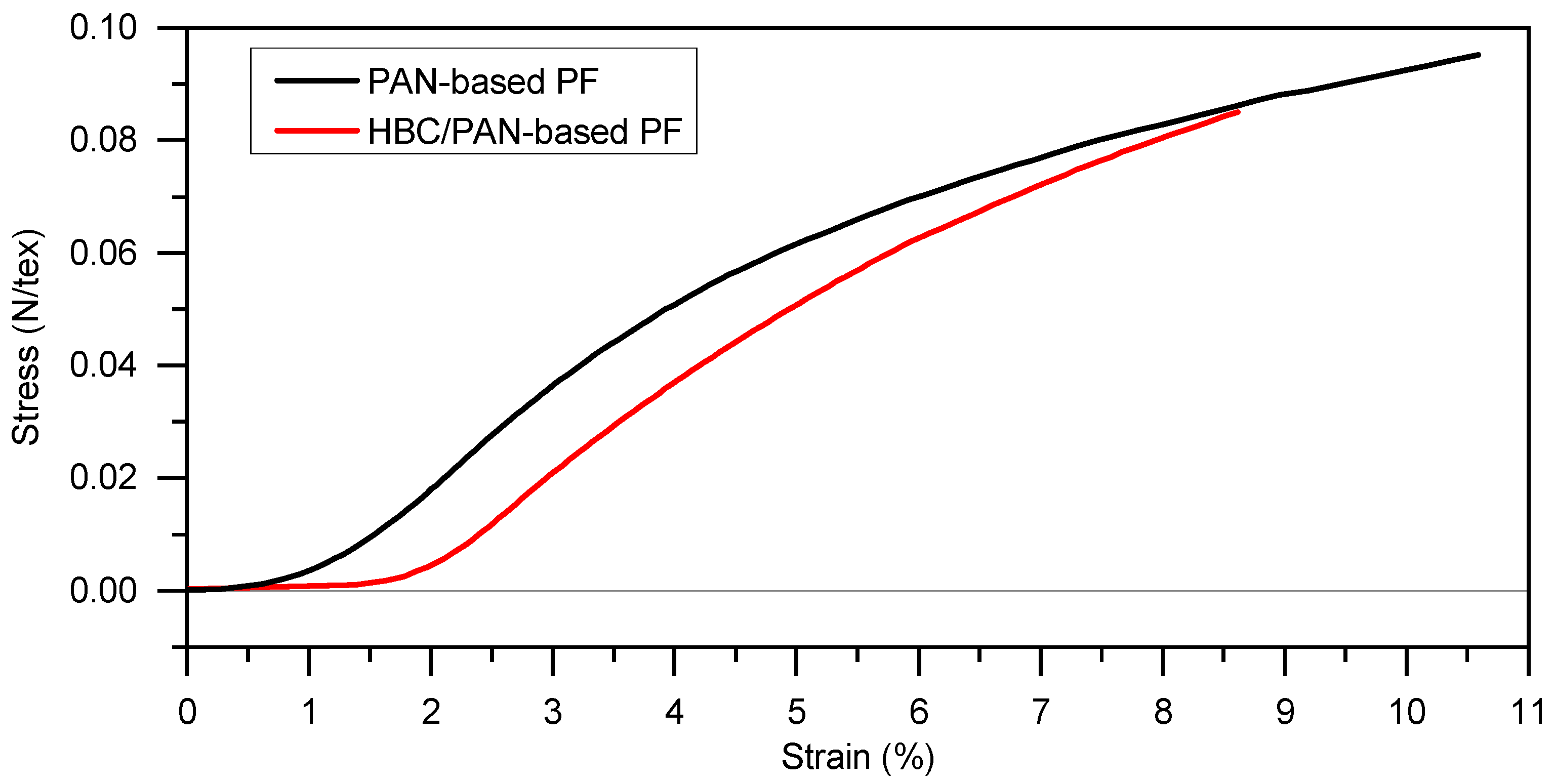
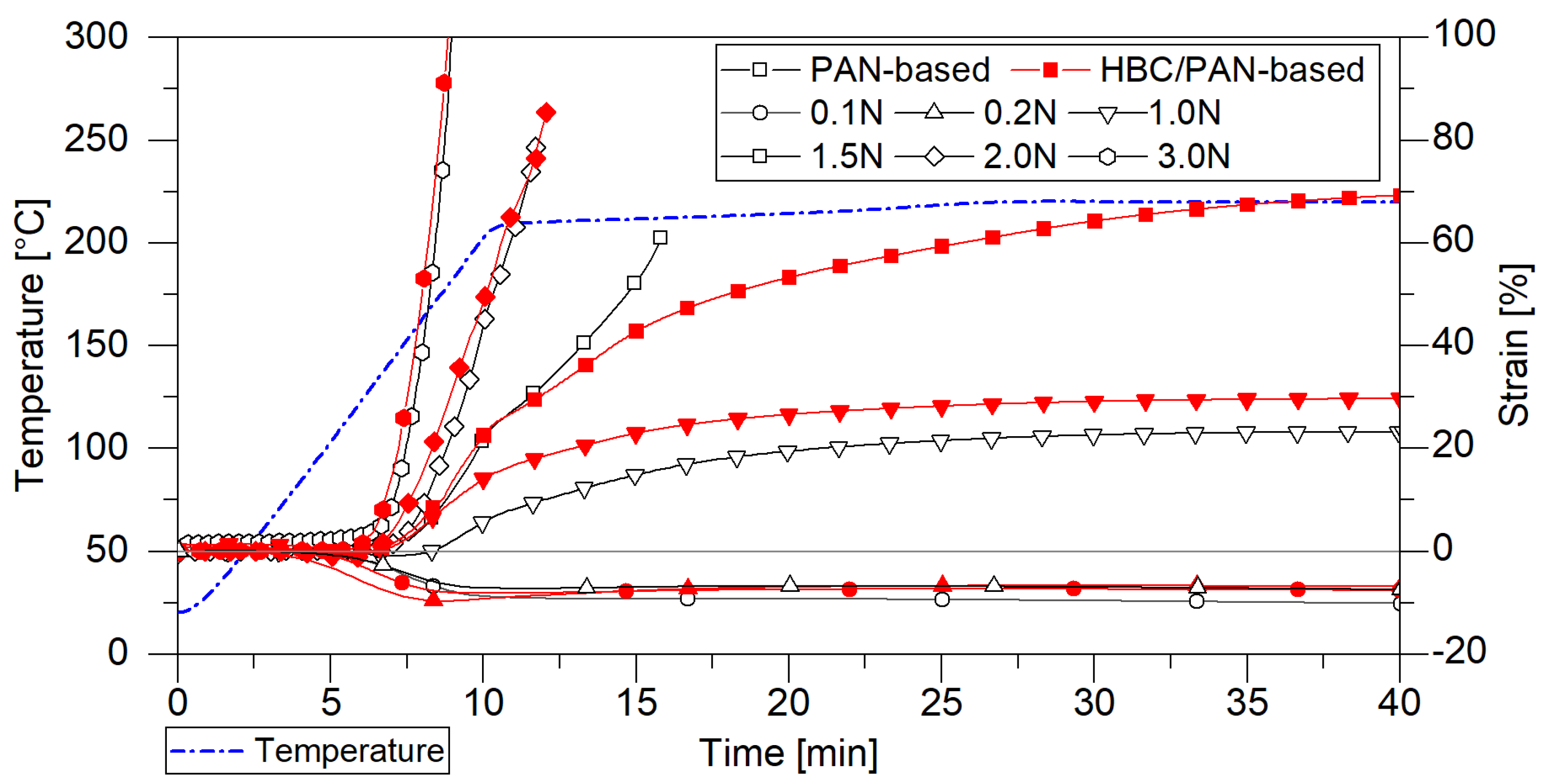
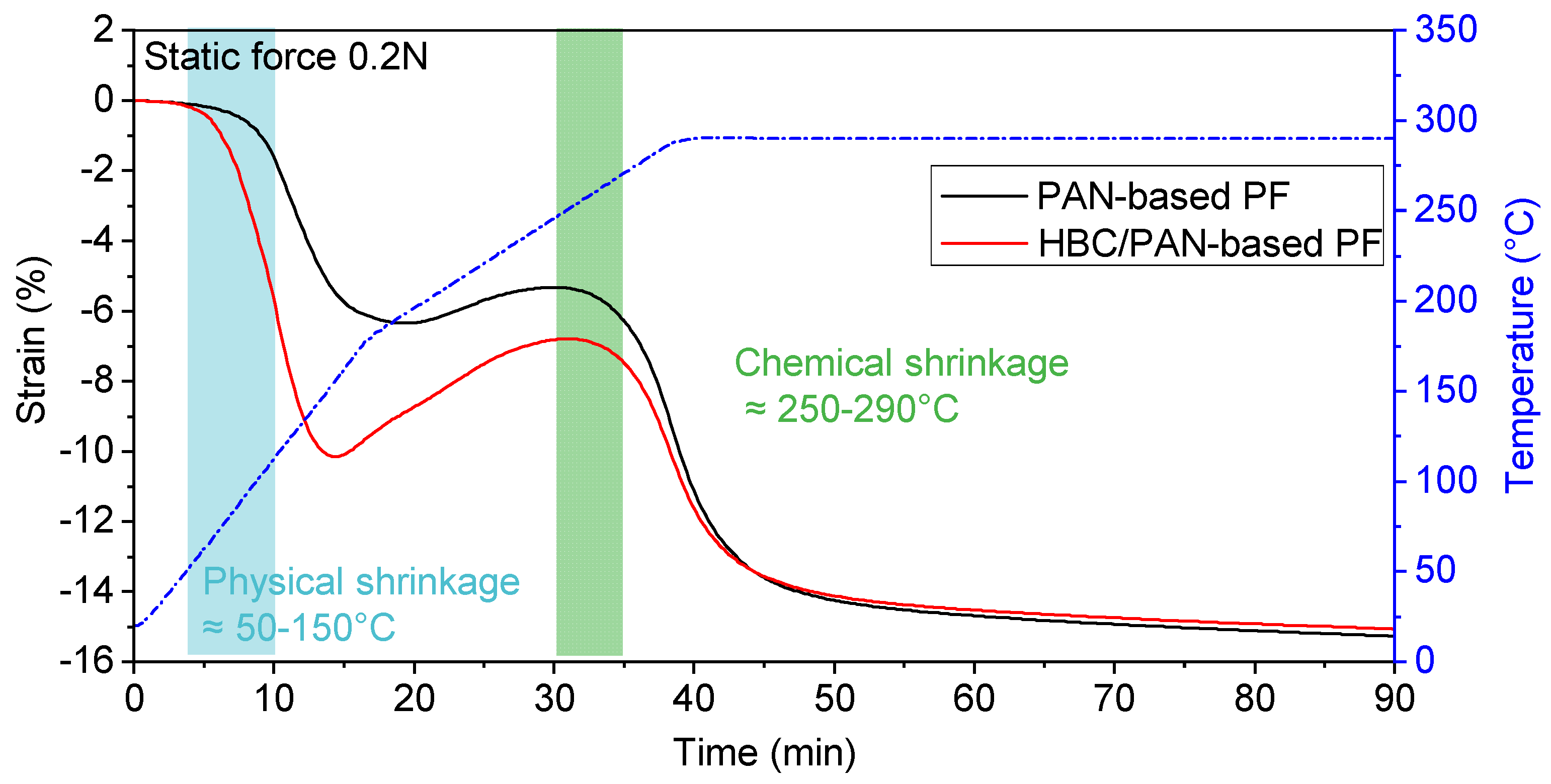
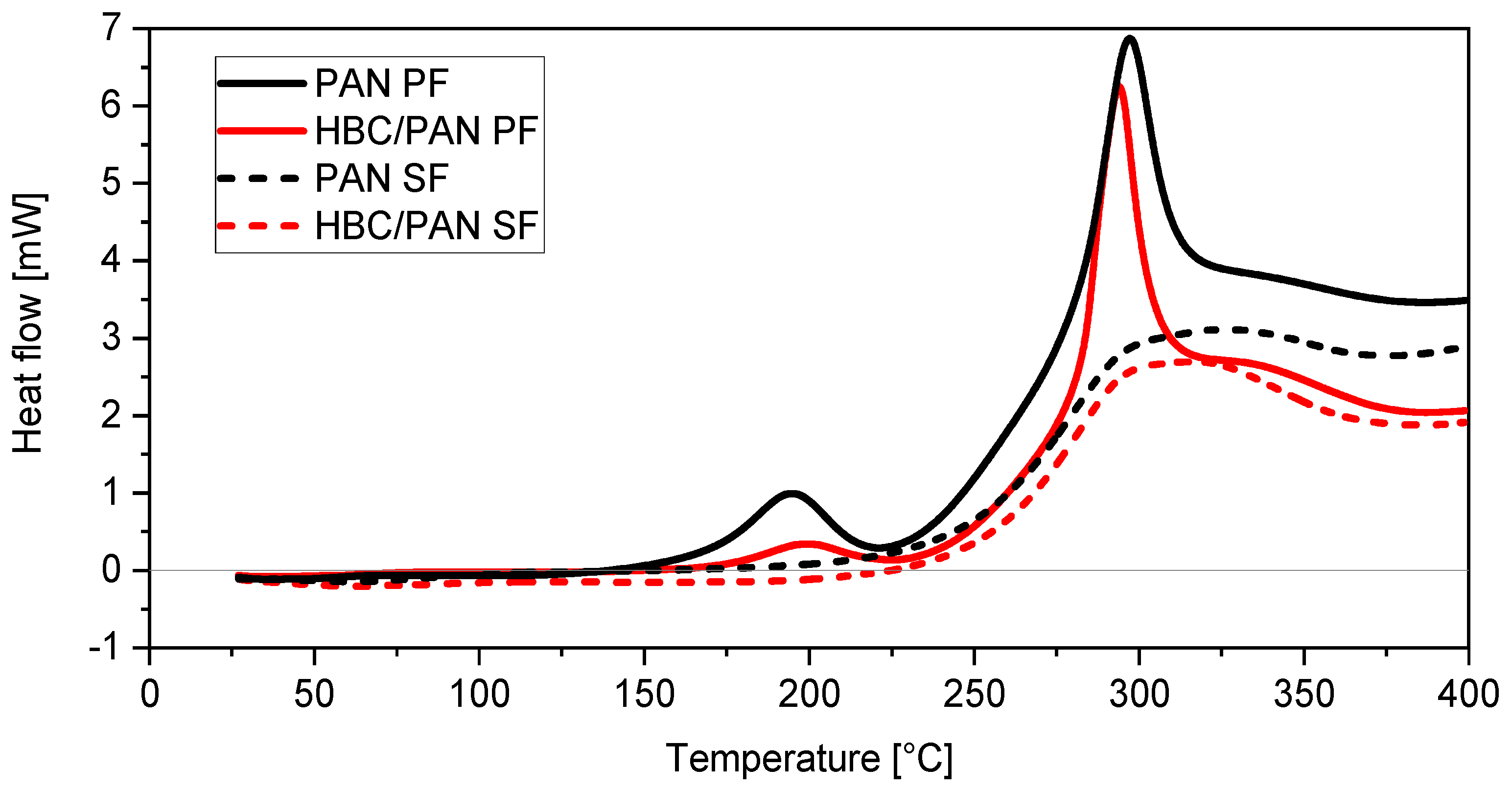
3.1. Mechanical Properties and Thermal Behavior of PAN and HBC/PAN Precursor Fibers and Stabilized Fibers

DMA and DSC were used to examine the thermal and mechanical properties of PAN- and HBC/PAN-based PFs. Three stretching experiments were conducted using DMA to identify possible parameters for continuous stabilization. The first experiment provides the diagram in Figure 1, which shows the stretch-strain curves of both PFs.
Since continuous stabilization systems are stretch controlled, the PFs were stretched in the DMA and the resulting force was measured. The HBC/PAN-based PF can be stretched up to 1.5% at room temperature before a force resultant is measured at the DMA. In contrast, the PAN-based PF shows an increase in the stress-strain curve already at the beginning of the stretching. Thus, HBC/PAN-based PF shows a higher stretching tolerance and, accordingly, a potentially higher stretch ability. The time-delayed responses to deformation suggest crystallinity differences between the two PFs, which will be discussed in the background of further experiments. Each PF can withstand a stretching of at least 9% at room temperature. Due to the maximum possible tensile force of 18 N of the test facility, no maximum value for stretching could be determined.
An additional experiment with the DMA was conducted to provide information about the applicable force range within the first heating zone of the continuous stabilization line (Figure 2).
The DMA oven chamber was heated up from room temperature to 220 °C and kept at a constant temperature for 15 min, approaching the conditions of continuous stabilization in the first heating zone. Meanwhile, constant forces between 0 N and 3 N were applied to investigate the possible stretching. Both fibers shrink at a load of 0.1 N and 0.2 N and rupture after a few minutes at a load of 2 N and 3 N. The tests with 0.2 N and 1 N tensile force reached a steady-state stretching and were selected as process limits for both PFs. When heated under a load of 1.5 N, the HBC/PAN-based PF can be stretched by up to 70%, whereas the unmodified PF constricts and finally breaks after only 10 min. The HBC thus seems to improve the elasticity of the fiber. This indicates that the HBC/PAN-based PFs could be more stretchable also under increased temperature and therefore reach a higher PAN precursor polymer orientation similar to the behavior in CNT/PAN [25]. For direct comparison, 0.2 N and 1 N have been selected as process limits in continuous thermal conversion.
The third investigation using DMA should provide information about the different shrinkage behavior of PAN- and HBC/PAN-based PFs to better control the continuous stabilization process, especially during heat up (Figure 3).
Starting at room temperature, the fiber was heated to 290 °C with a constant force of 0.2 N, which has been previously determined as a lower process limit for steady-state conversion in DMA (see Figure 2). HBC/PAN-based PF shrank between 50 °C and 150 °C significantly more than PAN-based PF at same loads. Afterward, the fibers elongated up to about 250 °C whereas the length increase of HBC/PAN-based PF is higher than for PAN fiber. However, with a constant 290 °C, the fiber lengths approached a constant value of −16% for both PFs. Due to the further, yet weak, shrinkage of the fibers, even after 90 min, the fibers did not seem to be fully reacted nor respectively stabilized.
According to the studies of Fitzer and Müller (1971) [26], Fitzer and Heine (1986) [27], and Meinl et al. (2016) [28] the fiber shrinkage between 50–150 °C is referred to as the physical shrinkage of the fibers due to entropic relaxation. The area between 225 and 300 °C refers to the chemical shrinkage of the fibers. Since HBC/PAN-based PF was shrinking at 50–150 °C stronger than the PAN-based PF, there seems to be a more intensive entropic relaxation of the polymer chains due to incorporated HBC in the fiber. HBC probably interferes as a foreign molecule with agglomeration during coagulation in the spinning process. The modified fibers would therefore have a higher residual shrinkage potential, which confirms the observation of the DMA analysis. The chemical shrinkage was less pronounced for HBC/PAN-based PF, which means that the crystallization reaction is less intense for HBC/PAN-based PF. Therefore, HBC in the polymer seems to have a positive effect on creating a uniform structure in the fiber.
DSC was used to investigate the influence of HBC on thermal behavior of PF and SF (Figure 4). Both PFs heat flow graphs show the typical curve for PAN-based PF with a main peak at about 300 °C and a shoulder at about 340 °C [10], whereas HBC/PAN shows a main peak that is more pronounced and shifted to lower temperatures.
Moreover, a third peak at around 190 °C can be observed for the two PFs. In particular, the 190 °C peak appears much flatter for HBC/PAN-based PF than for its unmodified PF. Attributing this peak to the cyclization reaction [29], the nanoadditive would inhibit the formation of ring structures within PAN. Disrupted PAN agglomeration means larger steric vacancies between PAN polymer chains resulting in a diminished cyclization reaction. The results fit with the observed larger physical shrinkage for HBC/PAN-based PF during heat up (Figure 3). The 190 °C peak is not visible in the heat flow graphs of both SFs. Obviously, the reaction occurring in this temperature range is completely finished after continuous stabilization. Furthermore, it can be observed that the same amount of HBC/PAN-based PF releases less energy than PAN-based PF, which could facilitate the dissipation of reaction heat in industrial production. A similar effect was observed by Chae et al. [6], according to which PAN/CNT fibers have developed less heat during enthalpy studies compared to PAN fibers.
Based on the heat flow curves the enthalpies could be estimated from which the SI was calculated using Equation (1), shown in Table 4. A 6.8% increase in SI for the modified material can be observed compared to the reference material. Therefore, it could be assumed that HBC accelerates the stabilization reaction. The result of the density test supports this thesis, as the HBC/PAN reached a higher density than the PAN-based SF. Still, the large standard deviation of the SI of HBC/PAN suggests a greater inhomogeneity of the modified fiber compared to the PAN fiber. Despite the presumably greater inhomogeneity of the fiber, the DMA results show a better stretchability of the modified PF, which is a basic prerequisite for high-tensile CFs. A more homogeneous HBC distribution in PAN could therefore result in an even higher stretchability of the HBC/PAN-based PF. This should, in turn, further improve the mechanical properties of resulting CF.

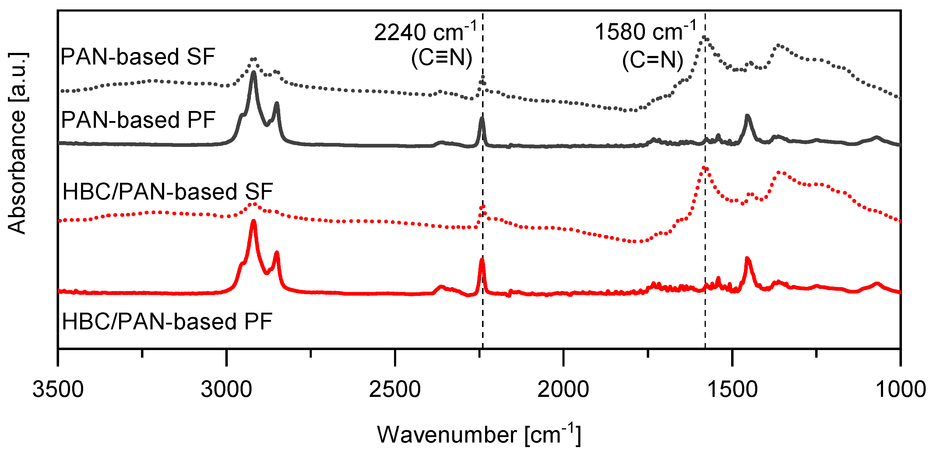
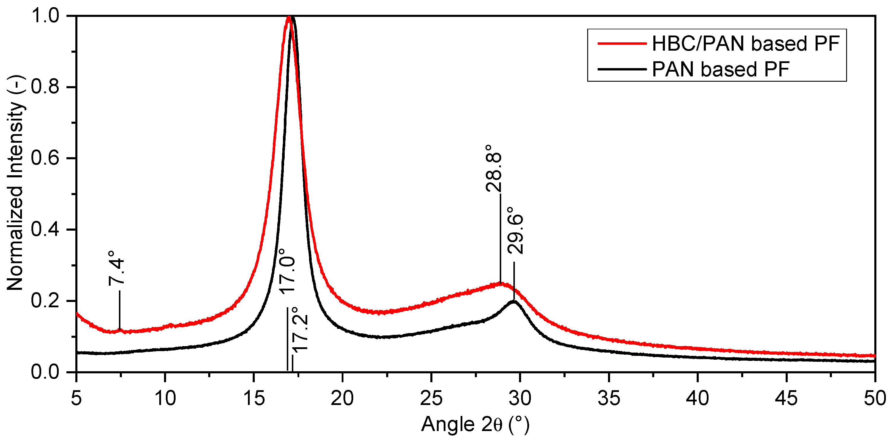
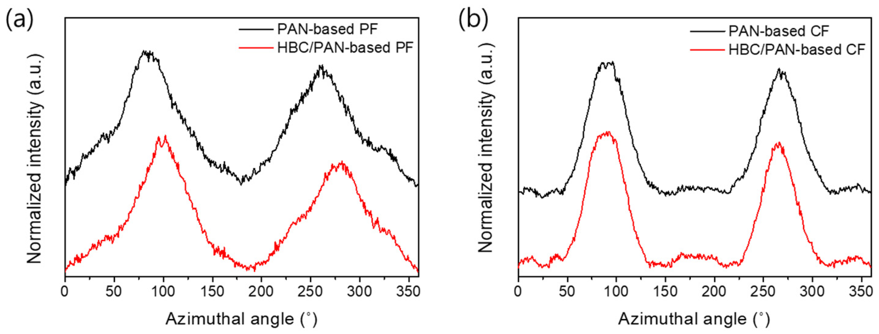
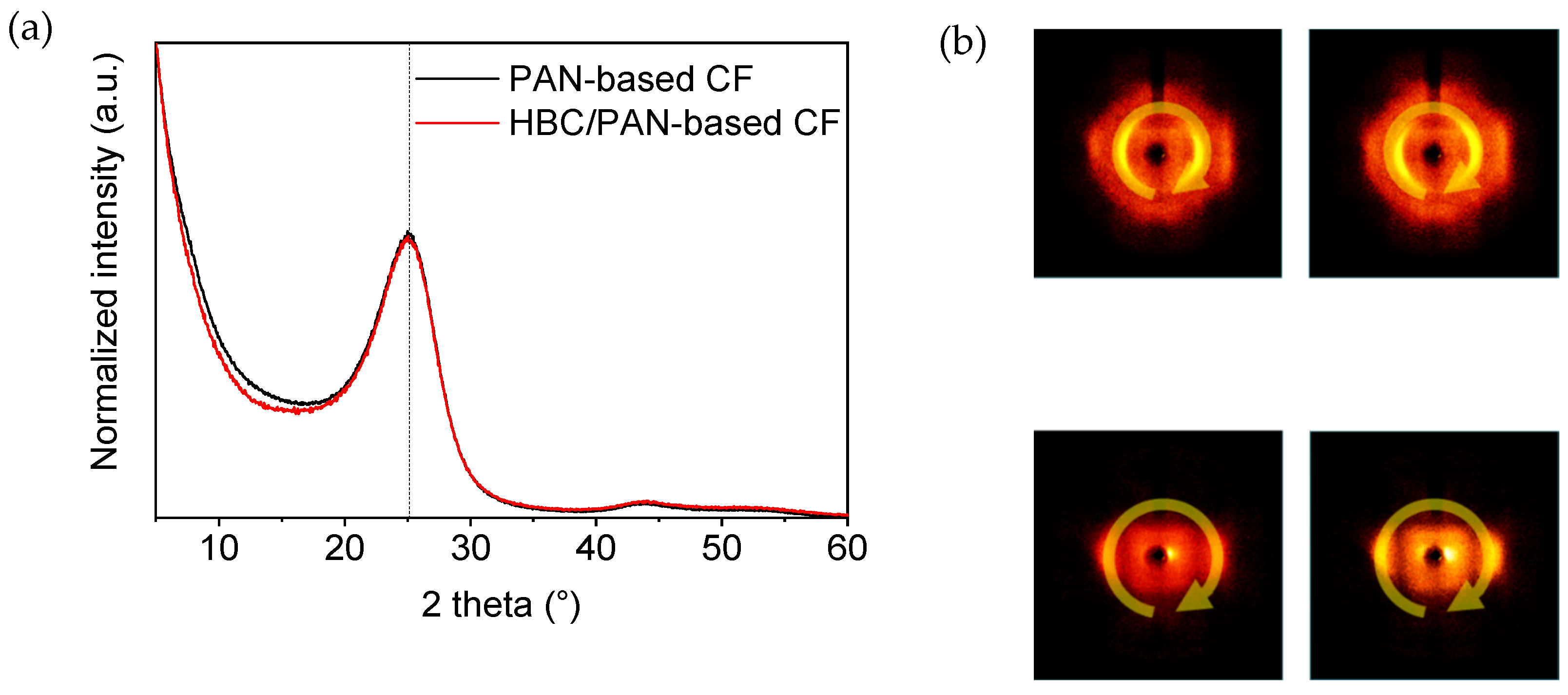
3.2. Structural Analysis of PAN- and HBC/PAN-Based PFs and SFs Using FT-IR and XRD

Spectral investigations using FT-IR were performed to detect differences in the chemical structure by adding HBC to PAN. Figure 5 shows the FT-IR spectra of the PFs and their corresponding SFs. The measurement was performed perpendicular to the fiber surface because the radiation detects material up to a penetration depth of 200 nm. Since the fibers have a diameter of up to 10 µm, only the outer part of the fiber, i.e., the skin, was measured. If no HBC molecule can be identified from the FT-IR spectra, the HBC molecules ought to be located further in the core of the fibers, which could be explained by shear forces during the spinning process (when the material is extruded from the nozzles). Clearly visible are the peaks of the nitrile groups C ≡ N at 2241 cm−1 and C = N at 1580 cm−1 [23,30,31], which are marked with vertical dotted lines.
The CI could be determined from these peaks, using Equation (2), listed in Table 4. The CI, also called extent of reaction (EOR), is an indicator of the progress of the stabilization reaction [22,32,33]. The CIs of HBC/PAN and PAN are identical, which means that the thermal stabilization can proceed unaffected by the addition of HBC. However, the peak at around 2363 cm−1, which can be associated with ionic amines C = NH+ [30], seems to be diminished for HBC/PAN-based SF compared to PAN-based SF. Additionally, the peak at about 2940 cm−1, attributed to the asymmetric C-H stretching of the -CH2 groups in the PAN structure, appears reduced for the HBC/PAN-based SF compared to the PAN-based SF which may be related to dehydration reactions [30]. Since calculation of the CI is not affected by these functional groups, the stabilization process does not seem to be influenced by the addition of HBC, yet they should still be considered in following investigations.
XRD was performed as a further structural analysis. The X-ray diffractograms were each normalized. Figure 6 shows the different shape of the spectral curves of the X-ray diffractograms of the two precursor types.
The dominant peak for both fibers is at 2θ≈17°. This peak and the peak at 29.6° can be attributed to the (100) plane and the (110) plane of the fiber diffraction pattern of PAN with hexagonal packing [34]. The estimated curves of HBC/PAN-based PF show less pronounced peaks in the (100) and (110) plane than for the PAN-based PF. Furthermore, the peaks of HBC/PAN appear broader and show a slight shift to smaller angles compared to PAN. Accordingly, the proportion of amorphous areas is more pronounced for HBC/PAN-based PF. Thus, the XRD results show a lower crystalline content of the HBC/PAN-based PF compared to the unmodified PF. These results match the results of the DMA, according to which HBC disturbs agglomeration during coagulation (Figure 3).
In contrast to this, the 1D XRD of PAN- and HBC/PAN-based CFs appeared equal (Figure A7a in Appendix B). Therefore, an effect of HBC on the formation of graphite structures was not evident here. Only the more precise 2D-XRD scans show differences in the two CFs investigated (Figure A7b in Appendix B), which are also visible in the evaluated spectral curves shown in Figure 7. Narrower FWHMs of the novel HBC/PAN-based CFs are visible, which indicate a higher orientation in crystal structure. Likewise, the decreased orientation factor of the modified PF (Table 5) confirms the structural improvement, calculated using Equation (3).

3.3. Mechanical Properties and Density of PAN- and HBC/PAN-Based Fibers

Diameter analyses and single filament tensile tests were carried out to determine the mechanical properties of the PFs and CFs. Microscopy images of both CFs in Figure 8 show an approximately circular cross-sectional area. An exemplary SEM image of a HBC/PAN-based CF is presented in Figure A8 including the method in Appendix C.
Due to low stretching in stabilization and carbonization, relatively large diameters of 9.0 ± 0.9 µm for PAN- and 7.8 ± 0.7 µm for HBC/PAN-based CFs were achieved compared to industrial CF with diameters of ~7 µm, e.g., T300. The diameter of HBC/PAN-based CFs is smaller than that of PAN-based CFs due to the shrinkage behavior of the PF during heat up, shown in Figure 3. HBC/PAN-based PF showed an increased physical shrinkage compared to PAN-based PF, which is accompanied by a decrease in thickness in the radial direction, i.e., a reduction in diameter.
Table 6 gives an overview of the mechanical properties of PFs and their resulting CFs. The two different PFs start at about the same textile properties: tensile strength of HBC/PAN-based PF is slightly higher than that of PAN-based PF whereas the Young’s modulus is similar. After stabilization and carbonization, both CFs exhibit tensile strengths of about 1900 MPa and at least a Young’s modulus of 150 GPa. HBC/PAN-based CF shows an improvement in Young’s modulus of about 38 GPa, which means an improvement of about +25%. This improvement could be explained by the enhanced orientation in the crystal structure of HBC/PAN-based CF shown in the 2D XRD results against the PAN-based CF in Figure 7.
Densities of PAN- and HBC/PAN-based PFs and CFs were estimated and listed in Table 6. Both PFs started with a mass density of approx. 1.15 g/cm3 and a linear density of 188.2 tex for PAN-based PF and 210.3 tex for HBC/PAN-based PF, respectively. After stabilization, an increased density for the modified fiber can be seen (Table 4). This difference in densities increases with the carbonization step. The observation complements the previously suspected support of the nanomaterial in the conversion of the fiber, which includes enhanced stabilization reactions as well as the formation of graphitic structures. However, both fibers did not reach the ideal SF density value of 1.38–1.42 g/cm3 [27] for higher mechanical properties. Future studies should investigate the impact of HBC content and heat-treatment processes on the structure of high-performance CF.

4. Conclusions and Outlook

In this work, we reported a novel PAN-based PF, which was modified by HBC. The novel HBC/PAN-based PF showed improved thermomechanical behavior compared to PAN-based PF. HBC as an additive seemed to support stabilization reactions, and HBC/PAN-based fibers showed potentially higher stretchability of PF and SF. With greater stretching and thus smaller diameters, an even higher positive impact on the mechanical properties of the resulting CF is expected. The modified CF improved the orientation of crystal structure evident in the 2D XRD result and achieved an increased Young’s modulus compared to PAN-based CF while maintaining tensile strength. In following studies, the spinning process for a more homogeneous distribution of HBC in PF should be investigated. Furthermore, optimized stabilization conditions and the influence of the HBC content to determine the supporting effect of HBC on structure formation will be the object of future studies. Moreover, alternative stabilization methods, such as plasma treatment, should be examined to reduce both the duration of stabilization and, thus, energy consumption.
This study could pave the way for manufacturing PAN fibers modified with various PAHs, which improve the thermomechanical properties during conversion to CF and result in a CF with a higher Young’s modulus. This can open up new ways to tailor CF properties through the interaction between raw material composition, process parameters, and structure formation.

Author Contributions

Conceptualization, R.P., D.J., D.S.J.W., M.R. (Mirko Richter), M.R. (Marcus Richter) and X.F.; Methodology, R.P., D.J., D.S.J.W., S.L., M.R. (Mirko Richter), M.R. (Marcus Richter) and X.F.; Validation, D.J., D.S.J.W., S.L. and H.J.; Formal analysis, R.P.; Investigation, R.P., D.J., D.S.J.W., M.R. (Mirko Richter) and K.V.; Resources, S.L., H.J., C.C., X.F. and M.G.; Data curation, R.P., D.J. and K.V.; Writing—original draft, R.P., D.J., M.R. (Mirko Richter) and M.R. (Marcus Richter); Writing—review & editing, R.P., D.J., D.S.J.W., S.L., H.J., C.C., X.F., T.B. and M.G.; Visualization, R.P., D.J. and T.B.; Supervision, D.S.J.W., S.L., H.J., C.C., X.F., T.B. and M.G. All authors have read and agreed to the published version of the manuscript.

Funding

This research received no external funding.

Data Availability Statement

Data is contained within the article and Appendix.

Conflicts of Interest

The authors declare no conflict of interest.

Appendix A

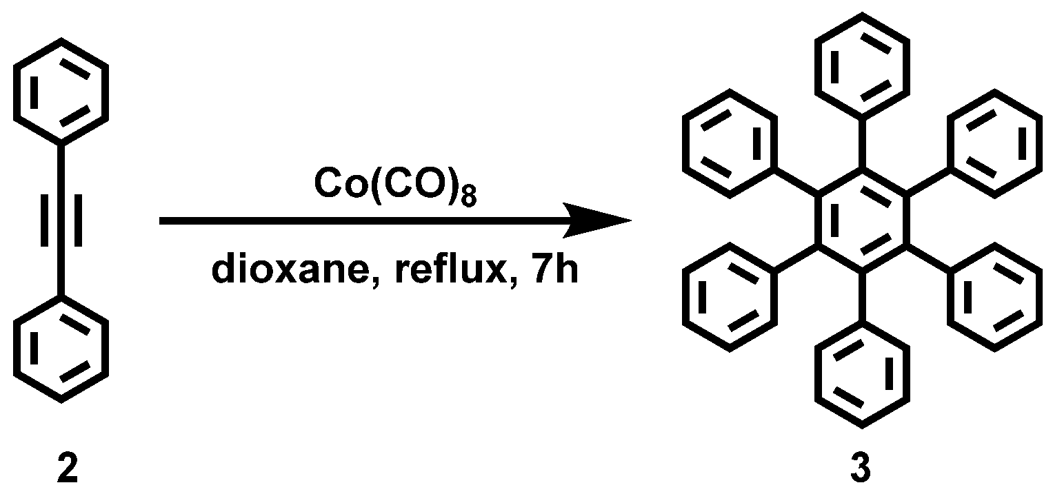
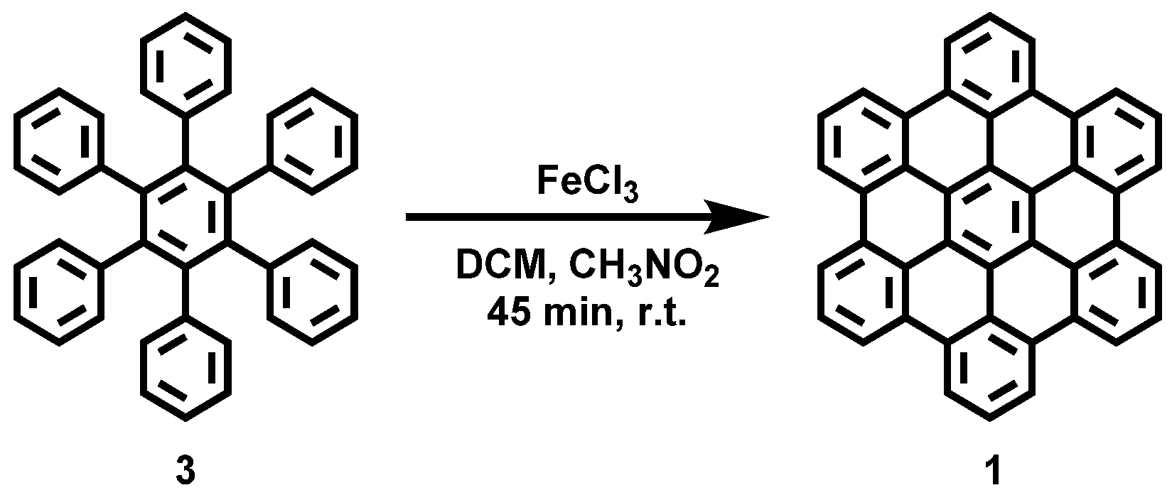
Appendix A.1. Synthesis of HBC (1)

The reactions were performed using standard vacuum-line and Schlenk techniques; work and purification of all compounds were performed under air and with reagent-grade solvents. Column chromatography was performed with silica gel (pore size 60 Å, 70–2230 mesh, 63–200 μm from Sigma Aldrich, St. Louis, MO, USA) and silica-coated aluminum sheets with fluorescence indicator from Merck were used for the thin layer chromatography.
Figure A1. Reaction scheme of the solution synthesis of Hexaphenylbenzene (3).
Fibers 11 00014 g0a1
Hexaphenylbenzene (3) was synthesized according to the literature procedure [35] and achieved with a yield of 63%.
Hexaphenylbenzene (HPB)(3): 1H−NMR (600 MHz, CD2Cl2): 6.93–6.82 (m, 30H) ppm. 13C−NMR (151 MHz, CD2Cl2): 141.1, 140.6, 131.7, 126.8, 125.5 ppm. The 1H- and 13C-NMR spectra of HPB (3) fits with the literature [36]. HR−MS (HR-MALDI-ToF): m/z ([M]+) = 534.2335; calcd. for C42H30: m/z = 534.2347; error = −2.25 ppm.
Figure A2. Reaction scheme of the solution synthesis of Hexabenzocoronene (1).
Fibers 11 00014 g0a2
Hexabenzocoronene (1) was synthesized according to the literature procedure [35] and achieved with a yield of 70%.
Hexabenzocoronene (1): HR−MS (HR-MALDI−ToF): m/z ([M]+) = 522.1400; calcd. for C42H18: m/z = 522.1408; error = −1.53 ppm.

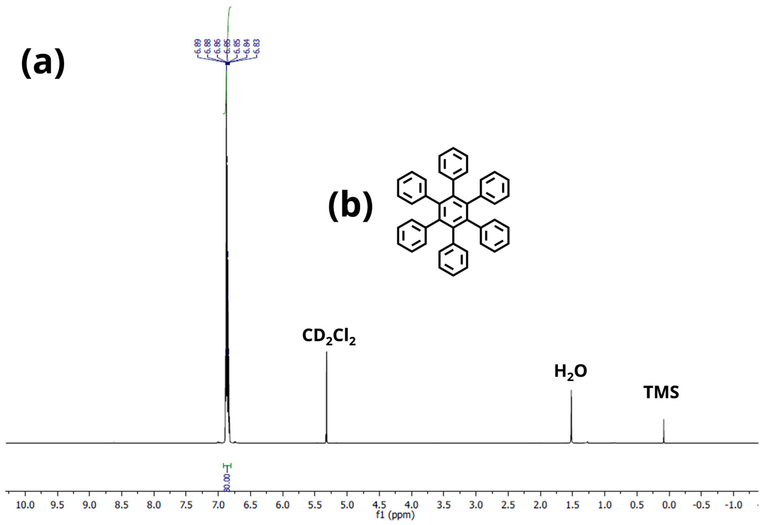
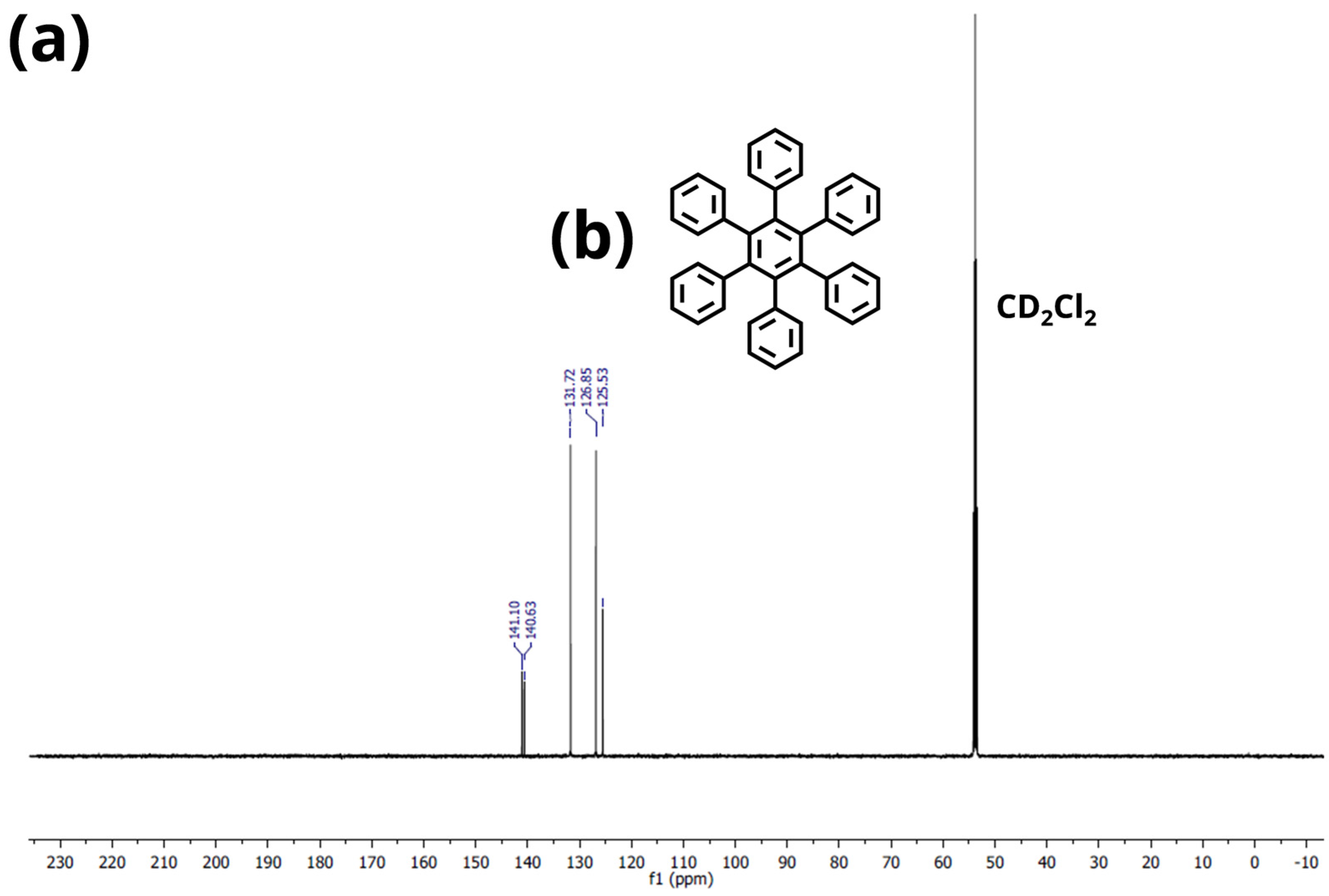
Appendix A.2. NMR Spectroscopy

Nuclear magnetic resonance (NMR) spectroscopy: All 1H and 13C-NMR measurements were recorded on a BRUKER AVANCE III 600 at 25 °C using standard pulse programs. Chemical shifts are reported as δ-values in ppm. Coupling constants (J) are given in Hertz (Hz). Chemical shift was referenced in regard to δ dichloromethane-d2 CD2Cl2 (δ(1H) = 5.32 ppm, δ(13C) = 53.8 ppm). The following abbreviation is used to describe peak patter as appropriate: m = multiplet.
Figure A3. (a) 1H−Sprectrum of HPB (3) in CD2Cl2. (b) Chemical structure of HPB (3).
Fibers 11 00014 g0a3
Figure A4. (a) 13C−Sprectrum of HPB (3) in CD2Cl2. (b) Chemical structure of HPB (3).
Fibers 11 00014 g0a4

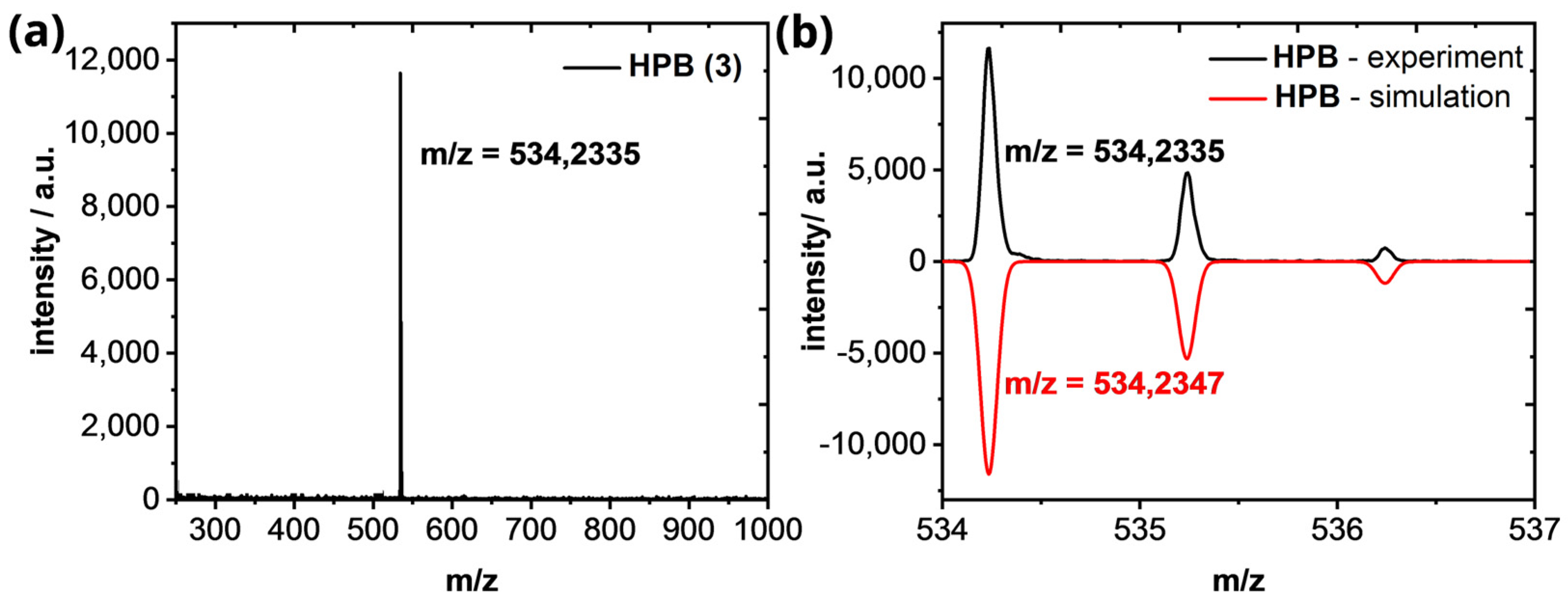
Appendix A.3. High-Resolution Mass Spectrometry of HPB (3) and HBC (1)

HR-MALDI-TOF MS spectra were recorded on a Bruker Autoflex Speed MALDI-TOF MS (Bruker Daltonics, Bremen, Germany) with Dithranol as the matrix. The preparation for all samples was performed in solid state.
Figure A5. (a) HR−MALDI−ToF of HPB (3). (b) Isotopic pattern of the [M]+-peak in comparison of the experimental (black line) and simulated results (red line).
Fibers 11 00014 g0a5
Figure A6. (a) HR−MALDI−ToF of HBC (1). (b) Isotopic pattern of the [M]+-peak in comparison of the experimental (black line) and simulated results (red line).
Fibers 11 00014 g0a6

Appendix B. XRD Measurement

Figure A7. (a) Normalized X-ray diffractograms of PAN- and HBC/PAN-based CFs measured with a 1D-XRD. (b) Image of 2D-XRD scan of PAN- and HBC/PAN-based CFs.
Fibers 11 00014 g0a7

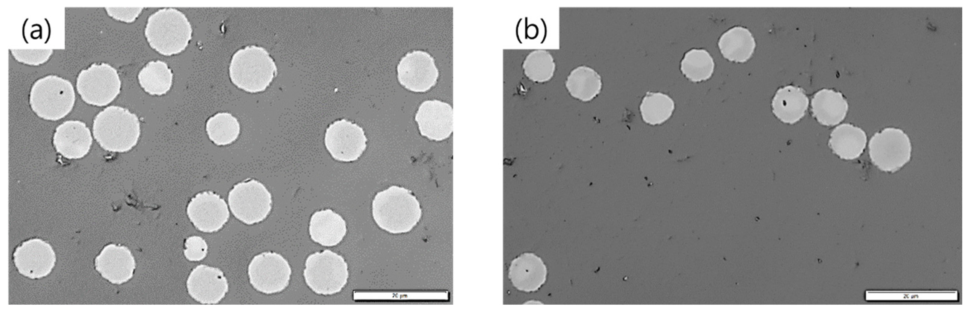
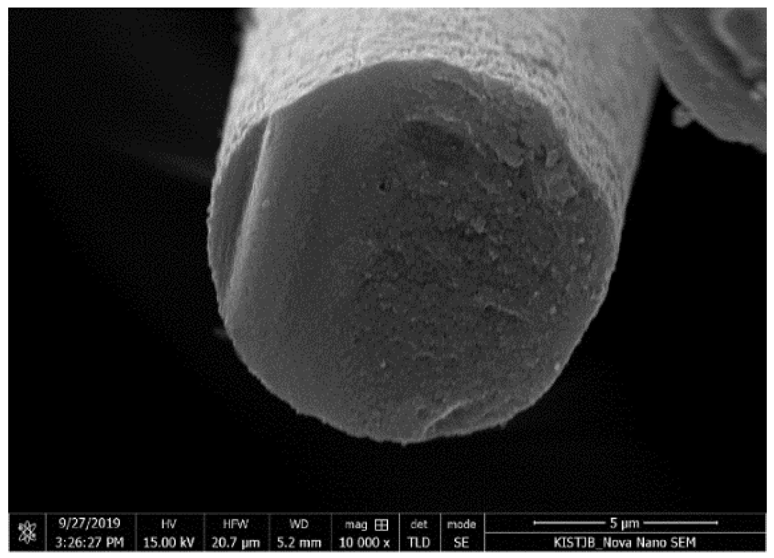
Appendix C. SEM Imaging

To investigate the cross-section of CF, scanning electron microscopy (SEM, NOVA NanoSEM 450, FEI, Hillsboro, OR, USA, software xTMicroscope Control v.6.3.0) with an acceleration voltage of 10 kV was performed. To increase the contrast, the samples were coated with platinum for 50 s in an ion sputtering coater. The current for the coating process was 5 mA. The picture was taken with a magnification of 35,000× in a vacuum chamber.
Figure A8. Cross-section image of HBC/PAN based CF, measured via SEM.
Fibers 11 00014 g0a8

References

  1. Jäger, H.; Cherif, C.; Kirsten, M.; Behnisch, T.; Wolz, D.S.; Böhm, R.; Gude, M. Influence of processing parameters on the properties of carbon fibres—An overview. Mater. Werkst. 2016, 47, 1044–1057. [Google Scholar] [CrossRef]
  2. Böhm, R.; Thieme, M.; Wohlfahrt, D.; Wolz, D.; Richter, B.; Jäger, H. Reinforcement Systems for Carbon Concrete Composites Based on Low-Cost Carbon Fibers. Fibers 2018, 6, 56. [Google Scholar] [CrossRef] [Green Version]
  3. Jäger, H.; Frohs, W. Industrial Carbon and Graphite Materials; Wiley: Hoboken, NJ, USA, 2021; Volume 1. [Google Scholar]
  4. Chae, H.G.; Choi, Y.H.; Minus, M.L.; Kumar, S. Carbon nanotube reinforced small diameter polyacrylonitrile based carbon fiber. Compos. Sci. Technol. 2009, 69, 406–413. [Google Scholar] [CrossRef]
  5. Chien, A.-T.; Liu, H.C.; Newcomb, B.A.; Xiang, C.; Tour, J.M.; Kumar, S. Polyacrylonitrile fibers containing graphene oxide nanoribbons. ACS Appl. Mater. Interfaces 2015, 7, 5281–5288. [Google Scholar] [CrossRef] [PubMed]
  6. Chae, H.G.; Minus, M.L.; Rasheed, A.; Kumar, S. Stabilization and carbonization of gel spun polyacrylonitrile/single wall carbon nanotube composite fibers. Polymer 2007, 13, 3781–3789. [Google Scholar] [CrossRef]
  7. O’Connell, M.J. Carbon Nanotubes: Properties and Applications; Taylor & Francis: Boca Raton, FL, USA, 2006. [Google Scholar]
  8. Chang, H.; Luo, J.; Gulgunje, P.V.; Kumar, S. Structural and Functional Fibers. Annu. Rev. Mater. Res. 2017, 47, 331–359. [Google Scholar] [CrossRef]
  9. Lyons, K.M. Tensile Testing and Stabilisation/Carbonisation Studies of Polyacrylonitrile/Carbon Nanotube Composite Fibers. Master’s Thesis, School of Materials Science and Engineering, Georgia Institute of Technology, Atlanta, GA, USA, 2012. [Google Scholar]
  10. Morgan, P. Carbon Fibers and Their Composites; Taylor & Francis: Boca Raton, FL, USA, 2005. [Google Scholar]
  11. Hill, J.P.; Jin, W. Self-Assembled Hexa-peri-Hexabenzocoronene Graphitic Nanotube. Science 2004, 304, 1481–1483. [Google Scholar] [CrossRef] [Green Version]
  12. Kirsten, M.; Freudenberg, C.; Cherif, C. Carbonfasern, der Werkstoff des 21. Jahrhunderts. Beton Stahlbetonbau 2015, 110, 8–15. [Google Scholar] [CrossRef]
  13. Stintz, M. Reine Technologien: Lehrveranstaltung; Institute of Process Engineering and Environmental Technology, TU Dresden: Dresden, Germany, 2017. [Google Scholar]
  14. Arbab, S.; Mirbaha, H.; Zeinolebadi, A.; Nourpanah, P. Indicators for evaluation of progress in thermal stabilization reactions of polyacrylonitrile fibers. J. Appl. Polym. Sci. 2014, 131, 40343. [Google Scholar] [CrossRef]
  15. Hou, Y.; Sun, T.; Wang, H.; Wu, D. A new method for the kinetic study of cyclization reaction during stabilization of polyacrylonitrile fibers. J. Mater. Sci. 2008, 43, 4910–4914. [Google Scholar] [CrossRef]
  16. Tsai, J.-S.; Hsu, H.-N. Determination of the aromatization index for oxidized polyacrylonitrile fibre by the differential scanning calorimetry method. J. Mater. Sci. Lett. 1992, 11, 1403–1405. [Google Scholar] [CrossRef]
  17. ISO 11566; Carbon Fibre—Determination of the Tensile Properties of Single-Filament Specimens. Composites and reinforcement fibres, Vernier; ISO-International Organization for Standardization: Geneva, Switzerland, 1996.
  18. DIN EN ISO 5079; Fasern—Bestimmung der Höchstzugkraft und Höchstzugkraftdehnung an Spinnfasern. Normenausschuss Materialprüfung: Physikalisch-technologische Prüfverfahren für Textilien; DIN-Deutsches Institut für Normung: Berlin, Germany, 1996.
  19. Nunna, S.; Creighton, C.; Fox, B.L.; Naebe, M.; Maghe, M.; Tobin, M.J.; Bambery, K.; Vongsvivut, J.; Hameed, N. The effect of thermally induced chemical transformations on the structure and properties of carbon fibre precursors. J. Mater. Chem. A 2017, 5, 7372–7382. [Google Scholar] [CrossRef]
  20. Nunna, S.; Maghe, M.; Fakhrhoseini, S.; Polisetti, B.; Naebe, M. A Pathway to Reduce Energy Consumption in the Thermal Stabilization Process of Carbon Fiber Production. Energies 2018, 11, 1145. [Google Scholar] [CrossRef] [Green Version]
  21. Nunna, S.; Naebe, M.; Hameed, N.; Creighton, C.; Naghashian, S.; Jennings, M.J.; Atkiss, S.; Setty, M.; Fox, B.L. Investigation of progress of reactions and evolution of radial heterogeneity in the initial stage of thermal stabilization of PAN precursor fibres. Polym. Degrad. Stab. 2016, 125, 105–114. [Google Scholar] [CrossRef]
  22. Zhu, Y.; Wilding, M.A. Estimation, using infrared spectroscopy, of the cyclization of poly(acrylonitrile) during the stabilization stage of carbon fibre production. J. Mater. Sci. 1996, 31, 3831–3837. [Google Scholar] [CrossRef]
  23. Fu, Z.; Liu, B.; Sun, L.; Zhang, H. Study on the thermal oxidative stabilization reactions and the formed structures in polyacrylonitrile during thermal treatment. Polym. Degrad. Stab. 2017, 140, 104–113. [Google Scholar] [CrossRef]
  24. Kim, M.A.; Jang, D.; Tejima, S.; Cruz-Silva, R.; Joh, H.I.; Kim, H.C.; Lee, S.; Endo, M. Strengthened PAN-based carbon fibers obtained by slow heating rate carbonization. Sci. Rep. 2016, 6, 22988. [Google Scholar] [CrossRef] [Green Version]
  25. Chae, H.G.; Sreekumar, T.V.; Uchida, T.; Kumar, S. A comparison of reinforcement efficiency of various types of carbon nanotubes in polyacrylonitrile fiber. Polymer 2005, 46, 10925–10935. [Google Scholar] [CrossRef]
  26. Fitzer, E.; Müller, D.J. Zur Bildung von gewinkelten Leiterpolymeren in Polyacrylnitril-Fasern. Die Makrornolekulare Chernie 1971, 144, 117–133. [Google Scholar] [CrossRef]
  27. Heine, M. Optimierung der Reaktionsbedingungen von thermoplastischen Polymer-Fasern zur Kohlenstoffaser-Herstellung am Beispiel von Polyacrylnitril. Ph.D. Thesis, Faculty of Chemistry, University of Karlsruhe, Karlsruhe, Germany, 1988. [Google Scholar]
  28. Meinl, J.; Kirsten, M.; Cherif, C.; Michaelis, A. Influence of PAN-Fiber Stretching during Thermal Treatment on the Stabilization Reactions. AJAC 2016, 7, 282–293. [Google Scholar] [CrossRef]
  29. Thünemann, A.F.; Ruland, W. Lamellar Mesophases in Polyacrylonitrile: A Synchrotron Small-Angle X-ray Scattering Study. Macromolecules 2000, 33, 2626–2631. [Google Scholar] [CrossRef]
  30. Zhao, J.; Zhang, J.; Zhou, T.; Liu, X.; Yuan, Q.; Zhang, A. New understanding on the reaction pathways of the polyacrylonitrile copolymer fiber pre-oxidation: Online tracking by two-dimensional correlation FTIR spectroscopy. RSC Adv. 2016, 6, 4397–4409. [Google Scholar] [CrossRef]
  31. Liu, J.; Zhou, P.; Zhang, L.; Ma, Z.; Liang, J.; Fong, H. Thermo-chemical reactions occurring during the oxidative stabilization of electrospun polyacrylonitrile precursor nanofibers and the resulting structural conversions. Carbon 2009, 47, 1087–1095. [Google Scholar] [CrossRef]
  32. Kim, S.-Y.; Lee, S.; Park, S.; Jo, S.M.; Lee, H.-S.; Joh, H.-I. Continuous and rapid stabilization of polyacrylonitrile fiber bundles assisted by atmospheric pressure plasma for fabricating large-tow carbon fibers. Carbon 2015, 94, 412–416. [Google Scholar] [CrossRef]
  33. Park, S.; Kil, H.-S.; Choi, D.; Song, S.-K.; Lee, S. Rapid stabilization of polyacrylonitrile fibers achieved by plasma-assisted thermal treatment on electron-beam irradiated fibers. J. Ind. Eng. Chem. 2019, 69, 449–454. [Google Scholar] [CrossRef]
  34. Habeeb, S.A.; Rajabi, L.; Dabirian, F. Production of polyacrylonitrile/boehmite nanofibrous composite tubular structures by opposite-charge electrospinning with enhanced properties from a low-concentration polymer solution. Polym. Compos. 2019, 41, 1649–1661. [Google Scholar] [CrossRef]
  35. Feng, X.; Pisula, W.; Takase, M.; Dou, X.; Enkelmann, V.; Wagner, M.; Ding, N.; Müllen, K. Synthesis, Helical Organization, and Fibrous Formation of C3 Symmetric Methoxy-Substituted Discotic Hexa- peri -hexabenzocoronene. Chem. Mater. 2008, 20, 2872–2874. [Google Scholar] [CrossRef]
  36. Yoshida, K.; Morimoto, I.; Mitsudo, K.; Tanaka, H. RhCl3/amine-catalyzed [2+2+2] cyclization of alkynes. Tetrahedron 2008, 64, 5800–5807. [Google Scholar] [CrossRef]
Figure 1. Stress-strain diagram for determination of the maximum stretching of PAN- and HBC/PAN-based PFs at room temperature using DMA (preload force at 0.2 N).
Fibers 11 00014 g001
Figure 2. Tensile force test simulating different loads in heating zone 1 in the DMA; comparison of the shrinkage behavior of PAN- and HBC/PAN-based PFs.
Fibers 11 00014 g002
Figure 3. Comparison of shrinkage behavior of PAN- and HBC/PAN-based PFs during heat treatment (via dynamic mechanical analysis).
Fibers 11 00014 g003
Figure 4. Enthalpy study showing heat flow diagrams of PAN (black)- and HBC/PAN (red)-based PFs (solid lines) and their SFs (dashed lines).
Fibers 11 00014 g004
Figure 5. FT-IR spectra of PAN- and HBC/PAN-based PFs and SFs.
Fibers 11 00014 g005
Figure 6. X-ray diffractograms of PAN- and HBC/PAN-based PFs.
Fibers 11 00014 g006
Figure 7. Normalized X-ray diffractograms of PAN- and HBC/PAN-based (a) PFs and their corresponding (b) CFs measured with a 2D-XRD.
Fibers 11 00014 g007
Figure 8. Microscopy images of (a) PAN- and (b) HBC/PAN-based CFs. Scale bar is 20 µm.
Fibers 11 00014 g008
Table 1. Spinning parameters of precursors.
PAN-Based FiberHBC/PAN-Based Fiber
ConcentrationHomogeneous PAN 18 wt.%PAN 18 wt.% + HBC 0.1 wt.%
Dope temperature70 ℃
Stretching ratio1:4
Coagulation bath temp.15 °C
Linear density188.2 tex210.3 tex
Table 2. Strain conditions for continuous stabilization line.
Trio 1 > DuoHZ1DuoHZ1 > Trio2Trio2 > DuoHZ2DuoHZ2 > DuoHZ3DuoHZ3 > DuoHZ4DuoHZ4 > Trio3Total Strain
Strain (%)−4.160.600.990.30.321.41–1.44−0.54
HZ: Heating zone.
Table 3. Parameter specification for continuous carbonization process.
ParametersLow-Temperature OvenCoupling ElementHigh-Temperature Oven
Temperature (°C)450/550/650/800400900/1050/1200/1400
Tension (cN)200–900
Dwell Time (min)≈4.5-≈5
Table 4. Stabilization index, cyclisation index, and density of PAN- and HBC/PAN-based SFs.
SF BasisSI in %CI in %Density in g/cm³
PAN45.9 ± 2.640.21.23 ± 0.02
HBC/PAN52.7 ± 11.140.21.27 ± 0.02
Table 5. Orientation factor of PAN- and HBC/PAN-based PFs and their corresponding CFs.
PFCF
PANHBC/PANPANHBC/PAN
Orientation
factor, f
0.650.690.750.77
Table 6. Mechanical properties of PAN- and HBC/PAN-based PFs and their resulting CFs.
PF BasisTensile Strength
in MPa
Young’s Modulus
in GPa
EAB
in %
Density
in g/cm³
PFPAN270 ± 207.1 ± 0.530.1 ± 6.51.15 ± 0.02
HBC/PAN300 ± 307.6 ± 1.133.8 ± 7.01.16 ± 0.02
CFPAN1890 ± 346152.5 ± 10.11.3 ± 0.21.51 ± 0.02
HBC/PAN1933 ± 278191.0 ± 11.31.1 ± 0.2 1.64 ± 0.02
Disclaimer/Publisher’s Note: The statements, opinions and data contained in all publications are solely those of the individual author(s) and contributor(s) and not of MDPI and/or the editor(s). MDPI and/or the editor(s) disclaim responsibility for any injury to people or property resulting from any ideas, methods, instructions or products referred to in the content.

