Article

Novel Fiber-Based Padding Materials for Football Helmets

1
Department of Mechanical Engineering, University of Massachusetts, North Dartmouth, MA 02747, USA
2
Department of Bioengineering, University of Massachusetts, North Dartmouth, MA 02747, USA
*
Author to whom correspondence should be addressed.
Fibers 2023, 11(11), 96; https://doi.org/10.3390/fib11110096
Submission received: 22 September 2023 / Revised: 16 October 2023 / Accepted: 3 November 2023 / Published: 8 November 2023

Abstract

:
An experimental study is performed to determine the head mechanics of American football helmets equipped with novel fiber energy absorbing material (FEAM). FEAM-based padding materials have substrates of textile fabrics and foam made with nylon fibers using electro-static flocking process. Both linear and angular accelerations of the sport helmets are determined under impact loads using a custom-built linear impactor and instrumented head. The effectiveness of padding materials and vinyl nitrile (VN) foam for impact loads on six different head positions that simulate two helmeted sport athletes in real-time helmet-to-helmet strike/impact is investigated. A high-speed camera is used to record and track neck flexion angles and compare them with pad effectiveness to better understand the head kinematics of struck players at three different impact speeds (6 m/s, 8 m/s, and 10 m/s). At impact speed of 6 m/s and 8 m/s, the FEAM-based padding material of 60 denier fibers showed superior resistance for angular acceleration. Although novel pads of VN foam flocked with 60 denier fibers outperformed with lowest linear acceleration for most of the head positions at low impact speed of 6 m/s, VN foam with no fibers demonstrated excellent performance for linear acceleration at other two speeds.

Graphical Abstract

1. Introduction

In recent years, sports-related traumatic brain injuries (TBIs) have become a major public health issue. Each year, nearly 1.6 to 3.8 million TBIs associated with sports happened in the United States (US) alone [1,2,3,4,5]. American football is one of the popular sports in the US and the players are becoming quite aggressive and physical, causing injuries, including head trauma. Based on recent studies, American football accounts for the highest percentage of mild TBIs or concussions in all sports [1,6]. There have been several efforts in American football to reduce the risk of concussions. They include improvements in helmet technology, proper tacking techniques, education of coaches, new materials, parents and athletic trainers, and rule changes [7,8,9,10,11]. Out of these, recently there has been great interest in developing new materials for helmets. The modern football helmets consist of a hard outer shell, padding materials, a face mask, and a chin strap. The hard outer shell distributes the applied impact force over the greater area of the interior pads under real-time sports impacts. Since the focus of this manuscript is developing new padding materials, this section is focused on the review of studies on various padding materials and their performance against linear acceleration, angular acceleration, and other metrics derived from above two accelerations.
In the majority of the American football helmets, the padding materials are the primary source of energy absorption or dissipation through compression and shearing deformations. The compression load primarily influences the linear acceleration of the head, whereas the shearing component causes the rotation of the head. It is important to note here that the bulk modulus of brain tissue is approximately 105 times greater than the shear modulus [12]. Hence, the brain tissue can be assumed as a fluid, being that its main mode of deformation is shear. Thus, rotational acceleration may be a greater cause of traumatic brain injury risk than linear acceleration [13,14]. The majority of traditional commercial helmet padding materials are made of polymeric foams. In earlier studies, Sances Jr. et al. [15] investigated the effect of four different padding materials (vinyl nitrile (VN) foam, commercial racing roil bar padding, Simpson racing roil bar padding, and metal air gap padding) on linear acceleration, angular acceleration, and head injury criterion (HIC) for both forehead and side head impacts at impact speed of 5.5 m/s. Metal air gap padding provided about 80% reduction in linear acceleration and 90% reduction in HIC compared to baseline conditions for forehead helmet impacts. The same padding material also performed well by reducing the angular acceleration by about 85% compared to the baseline conditions for side head impacts. Gimbel and Hoshizaki [16] studied the padding materials made of three densities of expanded polystyrene (EPS) and expanded polypropylene (EPP) impacted with EN 960 magnesium K1A headform of variable mass at five inbound velocities (1–5 m/s). Both inbound velocity and headform mass played a significant role on the linear acceleration of foam materials. For all types of five headform masses, as the foam density increased, peak linear acceleration increased for both EPS and EPP foams for the majority of inbound velocities. Ramirez and Gupta [17] developed novel temperature-stable viscoelastic polyurea foams as helmet liner materials and tested according to National Operating Committee on Standards for Athletic Equipment (NOCSAE) standard. The foam material demonstrated a reduction of 22% in linear acceleration and 25% reduction in severity index (SI) compared to VN 600 foam. Foster et al. [18] employed open cell polyurethane auxetic foams as padding materials in sports helmets. The helmet with auxetic foam decreased peak linear accelerations (p < 0.05) in relation to its standard counterpart of VN foam at the maximum impact energy under both the front and the side impacts. The SI value also showed a decrease by 11% for frontal impacts and 44% for side impacts. Recently, a novel commercial helmet design of Vicis Zero1 (VZ1, Vicis, Inc., Seattle, WA, USA) was recently reported where the helmet consists of a compliant outer shell and an internal columnar structure that deforms locally and buckles upon impact. In addition to internal columnar structure, viscoelastic padding bonnet was used for additional energy absorption [19]. Hanna et al. [20] utilized the Miura Ori folding pattern based auxetic metamaterials and developed eighty-one structural variations via the Taguchi method. Out of these variations, twenty-seven geometries were then additively manufactured using commercially available thermoplastic polyurethane, before being impacted at multiple velocities. Authors proposed an optimum geometry for padding materials with reduced linear acceleration across the test conditions and performed favorably when compared to current, elastomeric foam solutions. Sokoloff [21] developed a hydrophilic porous material swollen with fluid as padding material to reduce traumatic brain injuries in impact sports where friction experienced by the fluid as it is squeezed out of the porous material in an impact can “tune” the acceleration of the skull.
In case of modeling of football helmet padding materials, Decker et al. [22] developed a finite element model of Schutt Air XP Pro football helmet (that has padding components of conical impact absorbers and foam) was developed through three major steps: geometry development, material characterization, and model validation. They employed a Hybrid III dummy head–neck model and a NOCSAE head model and validated through a series of 67 representative impacts similar to those experienced by a football player and determined head linear acceleration, head angular velocity, and carriage acceleration for above impacts. Mills et al. [23] investigated effect of foam densification of four different configurations (soft, standard, stiff, and rigid) and at five different impact velocities (2.0, 5.5, 7.4, 9.3 and 12.3 m/s) of a Riddle Speed Classic helmet using LS-DYNA by adjusting the densification strain and using the NOCSAE linear impactor model. Cecchi et al. [24] again employed finite element methods to American football helmets featuring liquid shock absorbers for protecting against concussive and subconcussive head impacts. They determined a head acceleration response metric (HARM), which factors both linear and angular head kinematics. The liquid helmet model yielded the lowest value of HARM at 33 of the 36 impact conditions, offering an average 33% and 32% reduction over the existing helmet models at each impact condition in the subconcussive and concussive tests, respectively.
As discussed above, the majority of the previous work was focused on various kinds of polymeric foam padding materials. Recently, the novel pads made of fiber-based layers have shown impressive energy absorption capabilities when compared to current padding materials made of VN foam under impact compression loads [25,26,27] and impact shear loads of padding materials with pre-compression [28]. However, as presented above, the rotational acceleration that induces mTBI is due to the shear deformation of brain tissues [29,30,31,32,33,34] and how padding materials that can absorb energy under shear loads have a higher possibility of preventing mTBI in players. Towards this goal, for the first time, an effort is made in this study to characterize impact energy absorption of fiber-based energy absorbing materials (FEAM)-based padding materials according to the new NOCSAE standard [35]. It is hypothesized that fiber-based pads will provide a better attenuation of angular accelerations and neck flexion angles when compared to VN foams through the mechanisms of fiber buckling and friction between the fibers during the impact under combined compression and shear loads. A custom-designed linear impact tester along with a high-speed video camera is used to determine the peak linear acceleration (a), peak rotational acceleration (α), and neck flexion angle. The effect of padding type and impact velocity on above the parameters is determined and later compared with padding materials made from vinyl nitrile (VN) foam.

2. Experimental Methods and Design

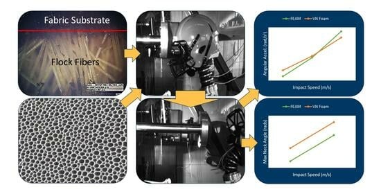
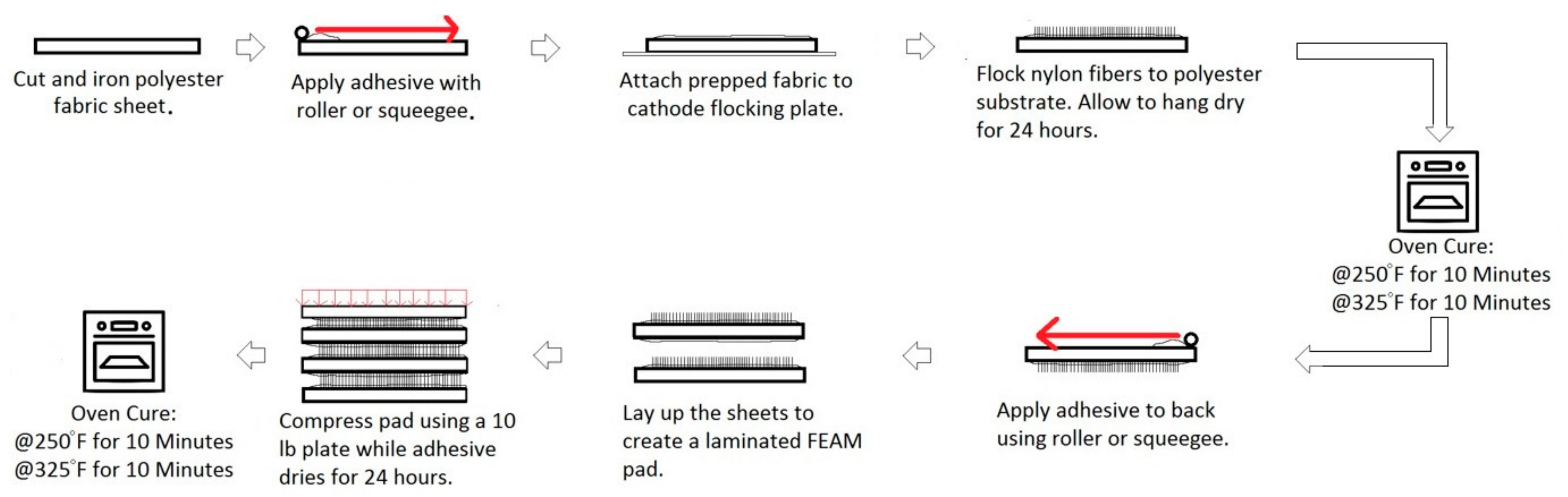
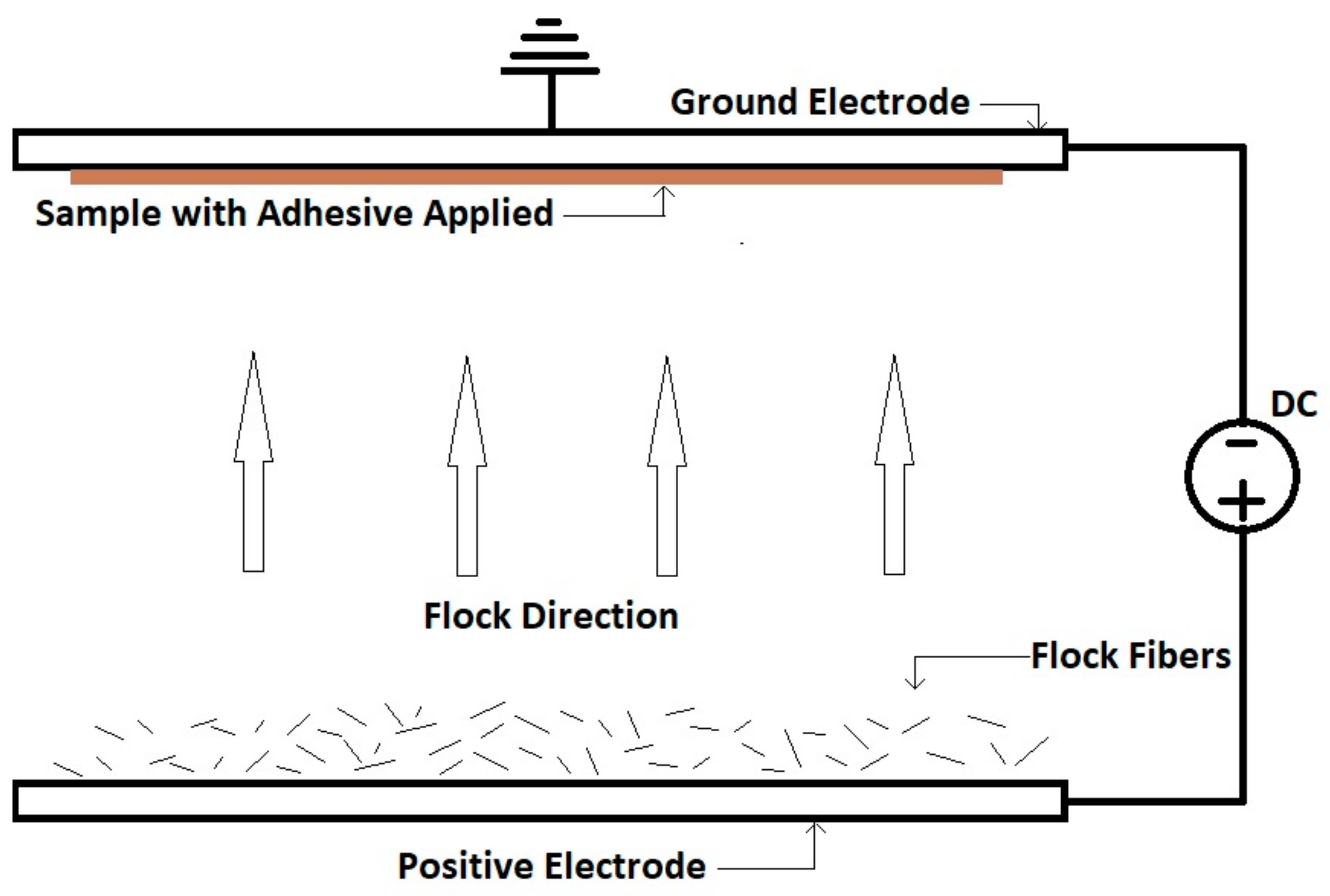
2.1. Fabrication of Padding Materials

FEAM-based padding materials are made using an electro-flocking fabrication process [25,26]. A schematic of the electro-flocking process is shown in Figure 1. The fabrication is shown in Figure 2. Initially, a thin film of adhesive (https://www.keypolymer.com/, accessed on 16 October 2023, Key Polymer FF3822 of Lawrence, MA, USA) is employed to a polyester fabric substrate (procured from www.fabric.com, accessed on 16 October 2023) using a draw down technique. Later, this fabric is affixed to the negative electrode of the flocking unit with the adhesive side face down. Nylon fibers (http://www.cellusuede.com/Nylon.aspx accessed on 16 October 2023, Cellusuede Products, Inc., of Rockford, IL, USA) are then dispersed evenly onto the positive electrode. An amount of 80 kV voltage potential is applied between the electrodes to levitate the nylon fibers up into the adhesive layer of the polyester substrate. This process is repeated to make the required number of fabrics attached with nylon fibers. These fabrics are then suspended at room temperature to dry for 24 h and then oven cured at 250 °F (121 °C) for 10 min followed by 325 °F (163 °C) for 10 min. After curing them in the oven, the other sides of the fabric (with no nylon fibers) are coated with a thin film of the above adhesive using a similar draw down technique. These flocked fabric substrates are then bonded together to make a thick pad where a top layer is covered with a fabric without nylon fibers. Lastly, the pads are kept in an oven once again at 250 °F (121 °C) for 10 min followed by 325 °F (163 °C) for another 10 min. When combined, FEAM and VN foam padding materials are made; some of the FEAM layers are replaced with the flocked foam sheets with the same fabrication process shown in Figure 2.
In this study, it is very important to match the geometry of the fabricated FEAM-based padding materials with commercially available pads that are installed inside the helmet. Therefore, instead of maintaining a constant number of layers, a constant thickness is maintained by using the data from our previous study to determine the approximate number of layers needed to generate a pre-defined thickness [20]. A commercially available helmet (https://www.riddell.com/riddell/en/Open-Catalogue/Helmets/c/t100, accessed on 16 October 2023, Riddell Speed Varsity Helmet of large size) is first purchased and torn down to determine the average padding thickness of VN foam used in the construction of said helmet. It is determined that this helmet has an average padding thickness of 25.06 ± 3.87 mm. This is defined as the target thickness for all novel fiber-based pads that are fabricated.
Each commercial pad is traced onto a piece of paper and then scanned into a computer to be reconstructed in SOLIDWORKS where the contact areas are estimated with some degree of certainty. It is determined through this method that commercial VN foam pads had roughly 692.92 cm2 of total contact area. Unfortunately, no statistical data was generated using this method due to the lengthy amount of time needed to rescan and generate cross sections of the pads; it is mostly used to ensure that manufactured fiber-based pads are relatively close in geometry to the commercial VN foam pads. Each group of pads is then weighed, and the total weight is divided by the total contact area to estimate the areal density of the different pad materials.
Since commercial padding is generally encased in a plastic inflatable bladder, there is a concern that the viscous drag of air inside the bladder might affect the control results, possibly leading to false conclusions. To prevent this from affecting results, the padding material is removed from the bladder, and a hook and loop method is used in all the tests to bind the padding to the internal structure of the helmet. This helps to remove the variance when comparing the novel fiber-based padding materials to the control VN foam.
This study also introduces a completely new material called “FF” padding. It is fiber-based material which uses thin VN Foam as its substrates, attempting to combine the shear impact absorption capabilities of fibers and the normal impact absorption capabilities of VN Foam. The “FF” pads are manufactured in the same fashion as the FEAM pads with the exception that the substrates are 3 mm thick VN foam sheets in place of the polyester fabric sheets.

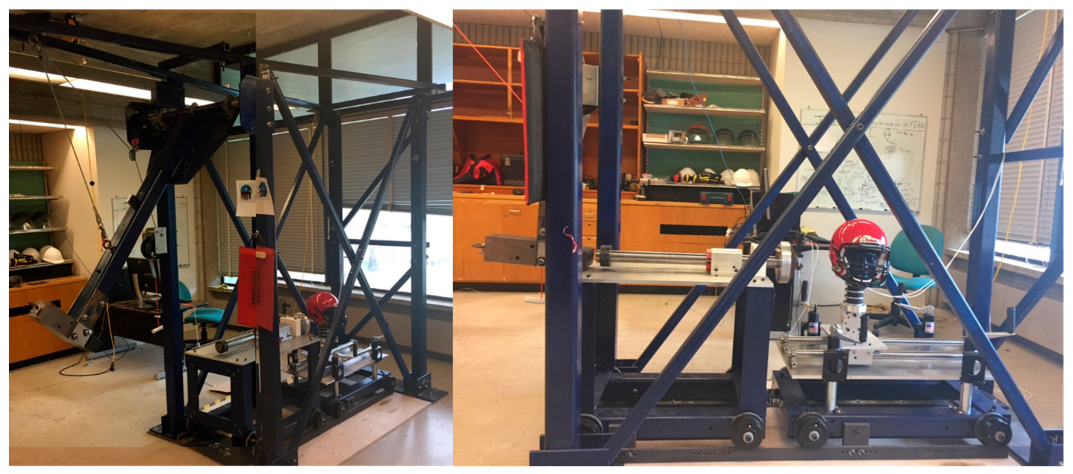
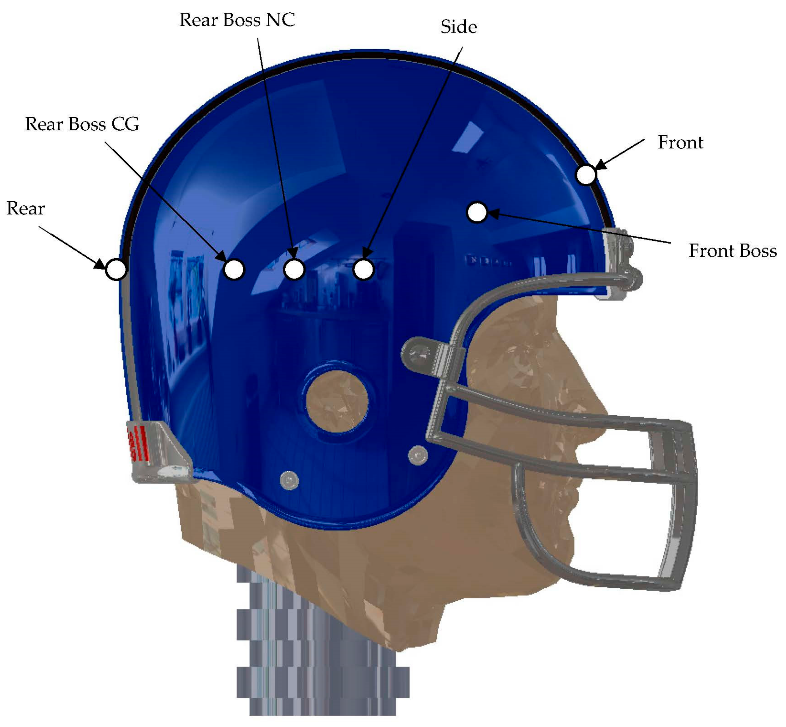
2.2. Experimental Setup

A custom-built linear impact tester as shown in Figure 3 is used to test different padding material configurations under simulated real time head-to-head impacts. The custom-designed and built impactor operates using a pendulum impact hammer to strike a linear impacting rod and is designed as per the NOCSAE standard [35]. The linear impacting rod in turn then strikes an instrumented and helmeted NOCSAE standard head at a predetermined velocity. The pendulum hammer has a mass of 127 kg and is 1.52 m long from the axis of rotation. The center of gravity lies 0.61 m from the axis of rotation. The hammer can be hoisted up to an angle of inclination of 115° from the natural hanging position with 0.1° accuracy.
The head is mounted upon a Hybrid III 50th percentile neck (Humanetics Inc., Farmington Hills, MI, USA) (https://www.humaneticsgroup.com/products/anthropomorphic-test-devices/aerospace-military/faa-hybrid-iii-50m, accessed on 16 October 2023) which is mounted upon a cart using a fixture and allows for positioning at a multitude of impact angles and positions. The neck is positioned according to the documentation provided by Humanetics Inc. A custom-built adaptor (provided by Virginia Tech, Blacksburg, VA, USA) is used to connect the neck properly to the head and to standardize the test setup with prior testing conducted by researchers [35]. At the center of gravity of the head, a six degrees of freedom sensor (www.dtsweb.com, accessed on 16 October 2023, 6DX Pro 2 K–18 K) is mounted. It captures all three translational accelerations (g) with a range of ±2000 g and all three rotational rates (rad/s) with a range of ±18,000 rad/s. The sensor also accommodates maximum bandwidths of 10 kHz for the accelerometers and 2 kHz for the angular rate sensors. The impacting rod has a laser guide which allows for the proper positioning of the NOCSAE head as defined for different impacting positions in the NOCSAE standard [35]. There is also a laser gate which acts both as a trigger and velocity measurement to ensure the impact speed is accurate and that data are acquired properly.
The sensor is routed to a data acquisition (DAQ) unit purchased from Measurement Computing (https://microdaq.com/manufacturers/measurement-computing.php?cat=330, accessed on 16 October 2023, MCC of Norton, MA, USA) which acquires samples at a rate of 500 kS/s and using the six channels’ yields 83.33 kS/s per accelerometer and angular rate sensor. All data are acquired via the LabVIEW custom program. The data are then imported to a custom MATLAB program for post processing (zero-phase low pass IIR Butterworth filter at 180 Hz for angular rate data and 1000 Hz for accelerometer data as per SAE J211) and analysis. Figure 4 shows an example of a raw and filtered impact trace. Notice the high frequency strain wave variations present in the raw data which requires filtration. If the data are not filtered, then when they are numerically differentiated, the noise is too great, and no valid conclusions can be drawn from the acceleration data. The resultant of accelerations in all directions is determined for both linear and angular accelerations. The second peak is the head-changing direction and oscillating around the rest position. Typically, this is negative in direction; however, when the resultant of the vectors is determined, they become positive.
Although data are collected for each degree of freedom, the resultant linear acceleration (a) and resultant angular acceleration (α) are of most interest, and more specifically, it is the magnitude of the resultant vectors which are usually recorded (resultant direction is usually of less importance). Angular accelerations are first calculated by differentiating the angular rate response. The resultant magnitude of a and α is then taken using a 3D magnitude formula.
For the first time, a high-speed camera (https://www.shimadzu.com/an/products/materials-testing/high-speed-video-camera/hyper-vision-hpv-x2/index.html, accessed on 16 October 2023, Shimadzu Hyper Vision HPV-X2) is used to capture simulated impacts. Typical settings for a recording included a 256-frame capture, with 1–2 ms interframe time, and 0.1–1 ms exposure time. The settings differed based on environmental lighting, artificial lighting positions, and impact velocities. A white light source using high intensity LEDs (Model: 900140B, voltage 100–240 VAC, Current 3.15 AMP) is used at full 100% setting. The light source is provided by Visual Instrumentation Corporation, Lancaster, CA, USA (http://visinst.com/leds/, accessed on 16 October 2023 ). The footage is used to calculate neck flexion angle and provide a correlation of padding material to neck flexion. Only in-plane impacts can be analyzed via this method due to complexity of out-of-plane rotations and single camera footage. Figure 5 shows how neck flexion angle is calculated from high-speed images.

2.3. Experimental Design

This study is designed to investigate how different padding materials installed into commercial football helmets affects both resultant linear and angular accelerations. Also, neck flexion angle is determined as an alternative means to determine padding effectiveness. Six different padding configurations as below are considered in the study.
  • As Purchased (with inflatable bladder)
  • VN Foam (no inflatable bladder)
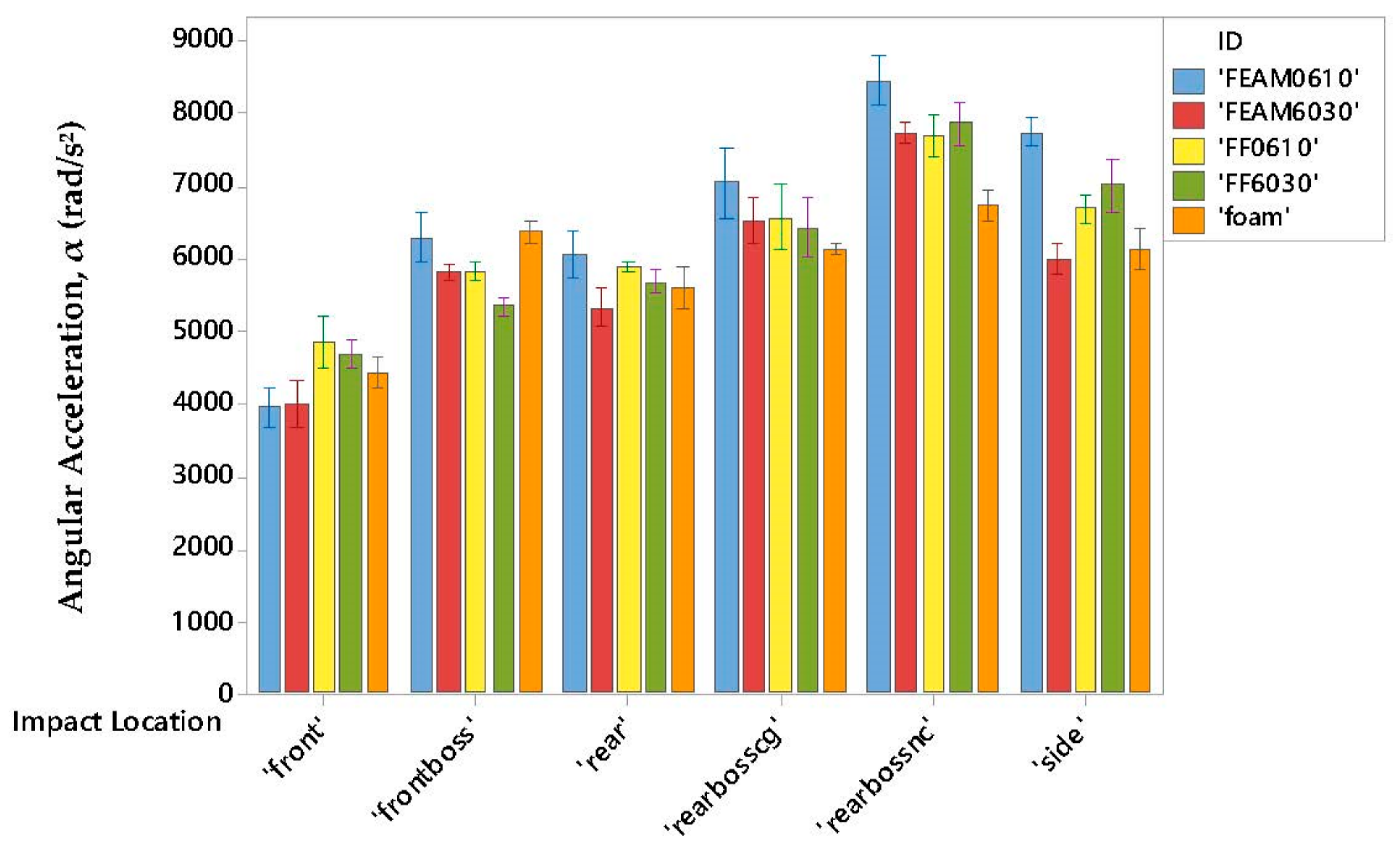
  • FEAM0610 (6 denier, 1 mm fiber length)
  • FEAM6030 (60 denier, 3 mm fiber length)
  • FF0610 (Same as FEAM0610 but with 3 mm thick VN foam substrates)
  • FF6030 (Same as FEAM6030 but with 3 mm thick VN foam substrates)
The density of each novel FEAM- and FF-based padding material was essentially kept constant around 248.63 ± 33 kg/m3, while the foam density was determined to be 127.58 kg/m3. Table 1 shows the data for each padding configuration. It is reiterated that the thickness is attempted to match the control group but, due to manufacturing variations, this is hard to achieve. The average thickness for FEAM- and FF- based padding materials, however, is maintained within one standard deviation of the measured thickness for the foam padding control. The volume fraction of the fibers and voids in each FEAM configuration is shown in Table 2. The optical microscopic images of all FEAM structures are shown in Figure 6, where the fibers take different angles between the substrates during the flocking process.
Each configuration is tested at six different impact locations as depicted in Figure 7 at three different impact velocities (6 m/s (low); 8 m/s (medium); 10 m/s (high)) for five times each to generate statistically significant data.

3. Experimental Results

3.1. Considerations of Inflatable Bladder

Prior to testing all padding configurations, the inflatable bladder that is molded around the VN foam padding of a commercial helmet was investigated. The worry was that this molded bladder may add viscous flow effects when the helmet is impacted showing significantly better performance than the FEAM padding configurations. To better understand the effects that this bladder played on impact resistance, the helmet was first tested in the as-bought condition and then the bladder was destroyed and VN foam removed and re-installed into the helmet using hook and loop attachment methods and tested again. Figure 8 and Figure 9 show that there was no major difference of both linear and angular acceleration between the as-bought condition and the VN foam by itself. The interval bars are based on 95% confidence intervals calculated using the student t-distribution.

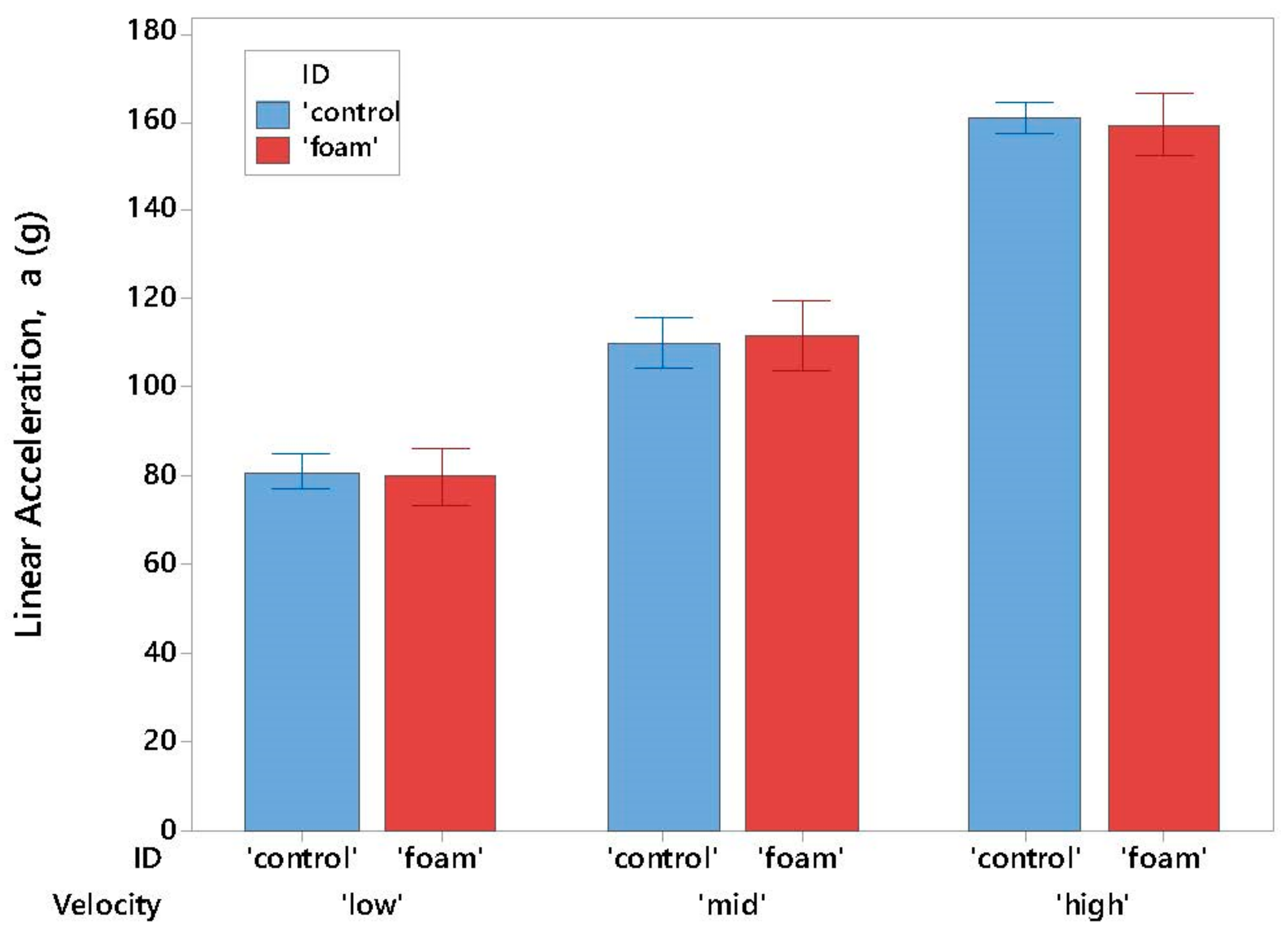
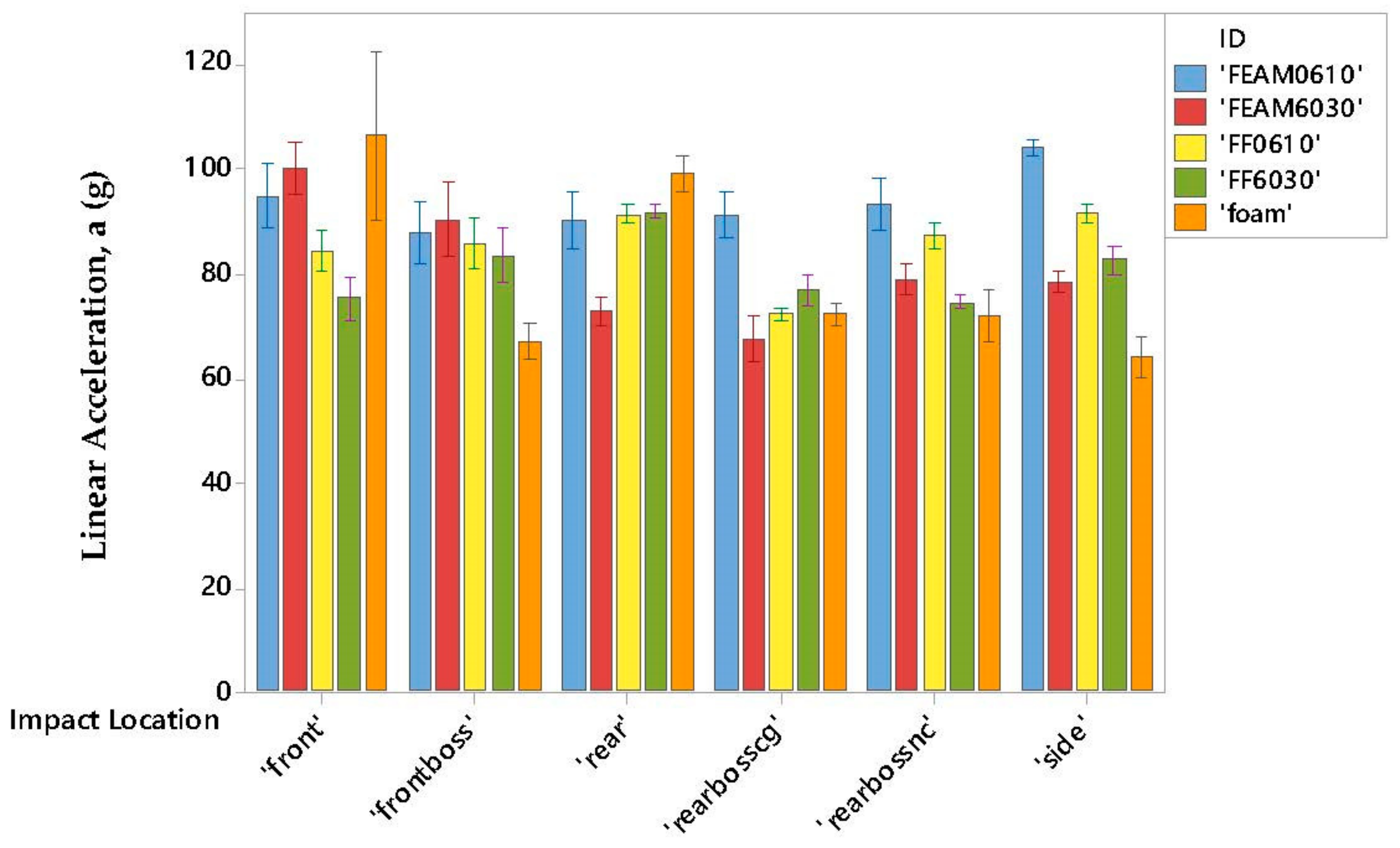
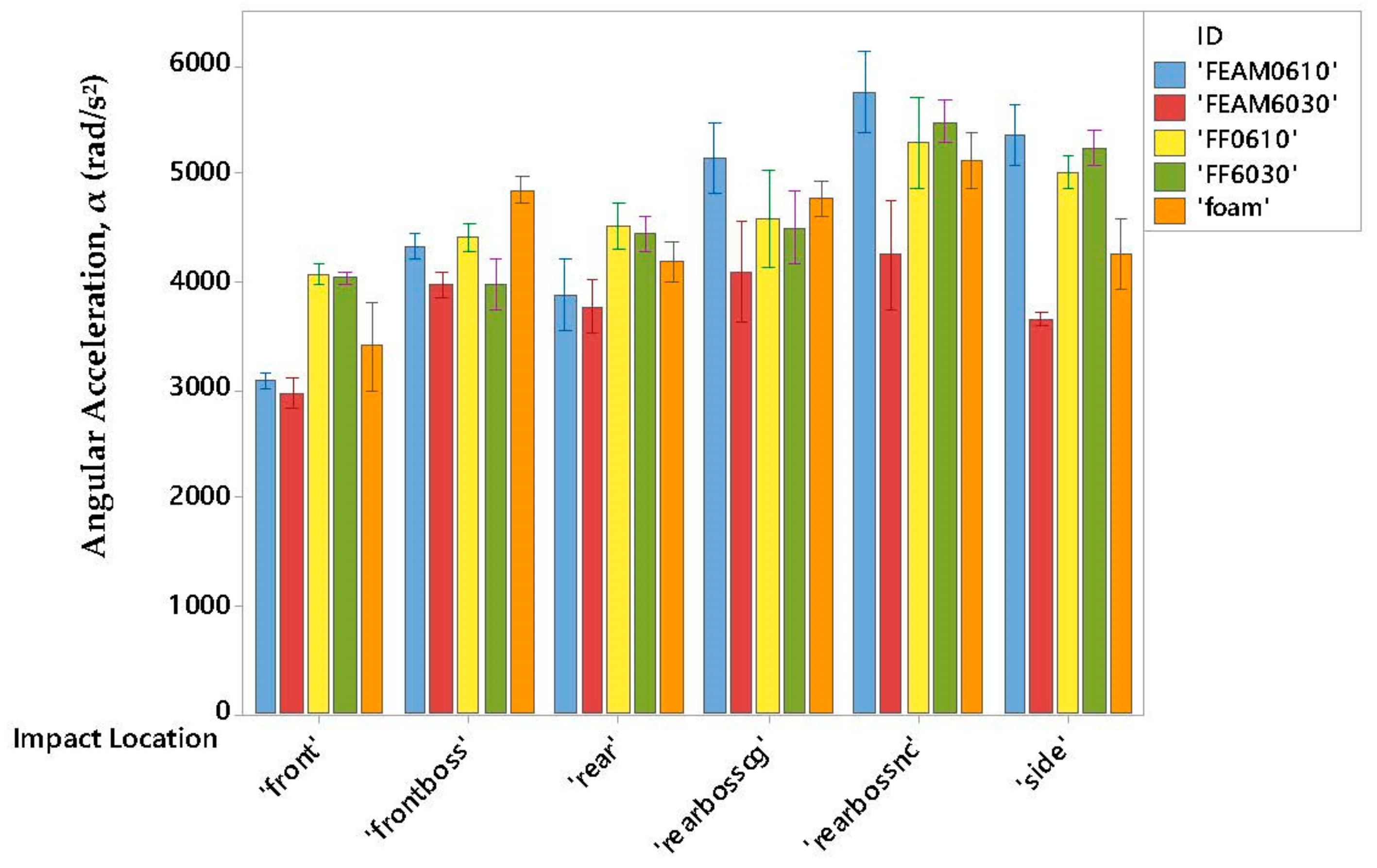
3.2. Low Impact Velocity

Figure 10 and Figure 11 show the resultant linear acceleration (a) and resultant angular acceleration (α) for each padding configuration and impact location under low velocity impact conditions (6 m/s). It can be observed that padding performance is highly dependent upon location and padding type. To summarize the data qualitatively, it can be noticed that at low impact velocities, at least one of the novel padding configurations outperformed foam for both metrics for frontal, rear, rear boss cg, and rear boss nc impact locations. It should be noted, however, that foam typically outperformed the novel paddings during low velocity impacts from the side and front boss impact locations.
The best material in attenuating rotational accelerations was the FEAM6030 configuration. It outperformed VN foam in every impact location significantly in terms of its ability to lower the rotational accelerations. It also performed relatively well in the linear acceleration metric, matching or exceeding foam, except for two impact locations: the side and front boss impacts. Since density was maintained to be relatively the same for all flocked material samples, there is some proof here that fiber-to-fiber interactions and fiber buckling are the cause for energy dissipation especially in reducing the angular accelerations. Unfortunately, it is impossible to know which dimension of the fiber (denier/diameter or length) has the most impact in reducing impact energy since the fibers chosen in this study have the same aspect ratio.
The question then becomes why does FEAM padding constructed with 60 denier perform much better than 6 denier? In the 6 denier case, the pads contain nearly 10× the number of fibers. Because there are so many more fibers and the paddings experience compression and shear loading that occur at the same time, the high fiber count causes individual fibers to be bundled together and experience the forces as a single larger fiber. Essentially, there is no space in which the fibers can buckle and, therefore, decreased attenuation of forces exist. Figure 8 and Figure 9 show that FEAM0610 was generally worse at lowering linear accelerations and angular accelerations, and that is because the fibers that can buckle are significantly reduced due to spacing and tight packing of the fibers when compared with the FEAM6030 pads.

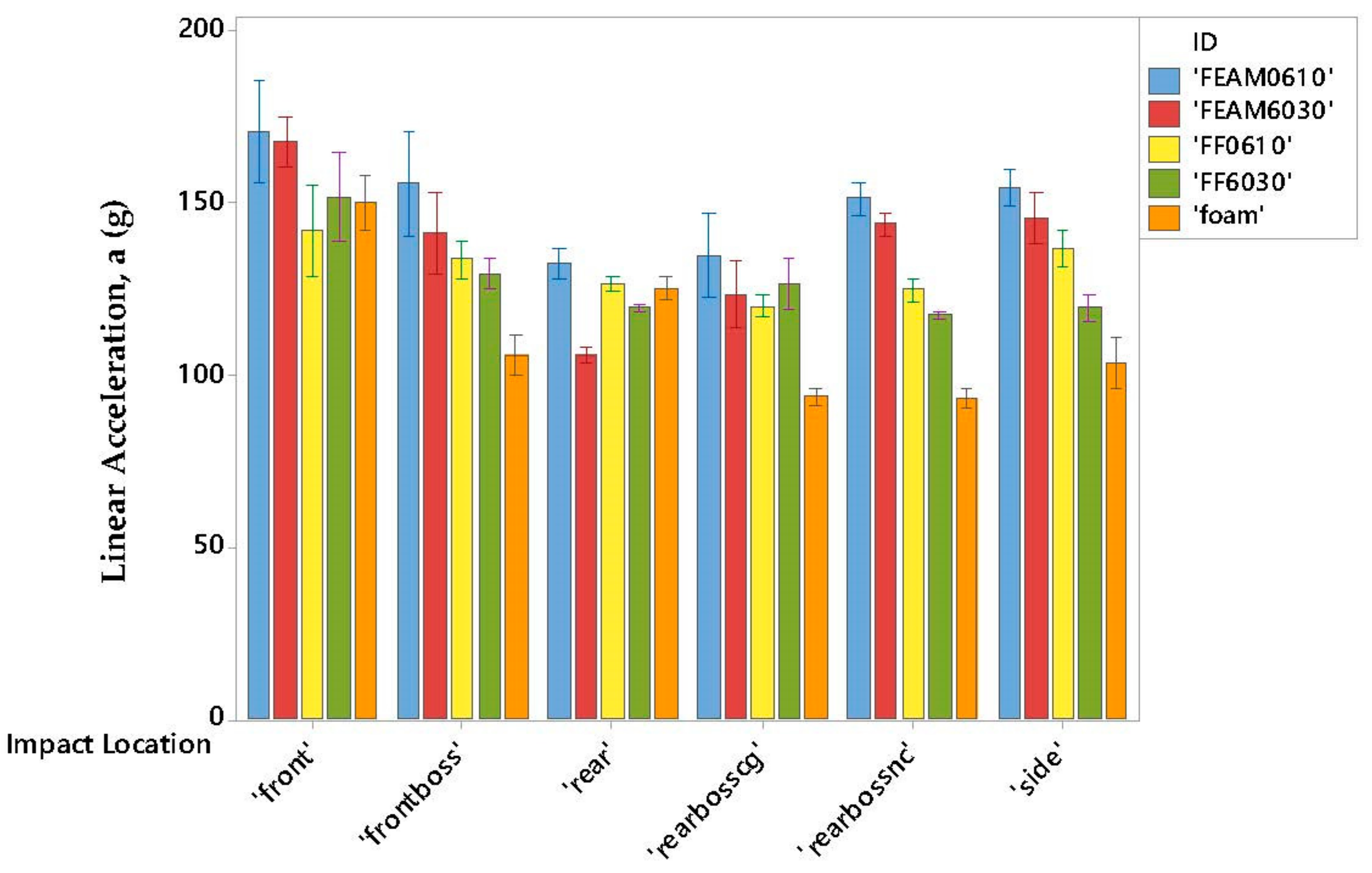
3.3. Medium Impact Velocity

The resultant linear acceleration and resultant angular acceleration for each padding configuration and impact location under medium velocity impact conditions (8 m/s) are shown in Figure 12 and Figure 13, respectively. It can be noticed again that padding performance is highly dependent upon location and padding type. Foam typically outperformed the novel paddings during medium velocity impacts during almost all impact locations for both metrics. Linear accelerations also demonstrated improved performance for the FEAM6030 padding when impacted from the rear as compared with foam. Rotational acceleration metric for FEAM6030, however, saw either equivalent or improved performance compared to foam for all impact locations other than the rear boss nc impact.
The best material in attenuating rotational accelerations was again the FEAM6030 configuration. It outperformed VN foam in almost every impact location, significantly in terms of its ability to lower the rotational accelerations except for the impact at the rear boss nc location. It is, however, performed relatively poorly in the linear acceleration metric in every impact except the rear when compared with foam. Finally, the rear boss nc impacts showed reduction in ability to attenuate rotational accelerations compared to foam. One of the more important data points of note is that FEAM6030 is able to maintain rotational accelerations below 6000 rad/s2, which is the proposed incidence for a 50% concussion risk as reported in previous studies [29,36,37,38,39,40].
Interestingly, a similar trend can be noticed here as that in the previous section. The FEAM6030 pads had significant improvements when compared with the FEAM0610 pads, this being again for the same reason. The high fiber density of the lower denier pads does not allow fibers to buckle. There is no space allowed for the fibers to buckle and many thin fibers act locally as a larger fiber by providing support to each other. Another interesting trend is noticed: when adding in foam substrates for the FF paddings, reduction of linear accelerations is seen compared to FEAM. Essentially, the padding acts more and more like a fully foam material. In the opposite vein, we see that the angular acceleration is increased when foam substrates are added. This could be accounted for the adhesive on the foam substrates that is used during flocking. The adhesive does not bond well with foam in general. A possible improvement could be to texture the foam surface before flocking in order to try and improve mechanical interlock.

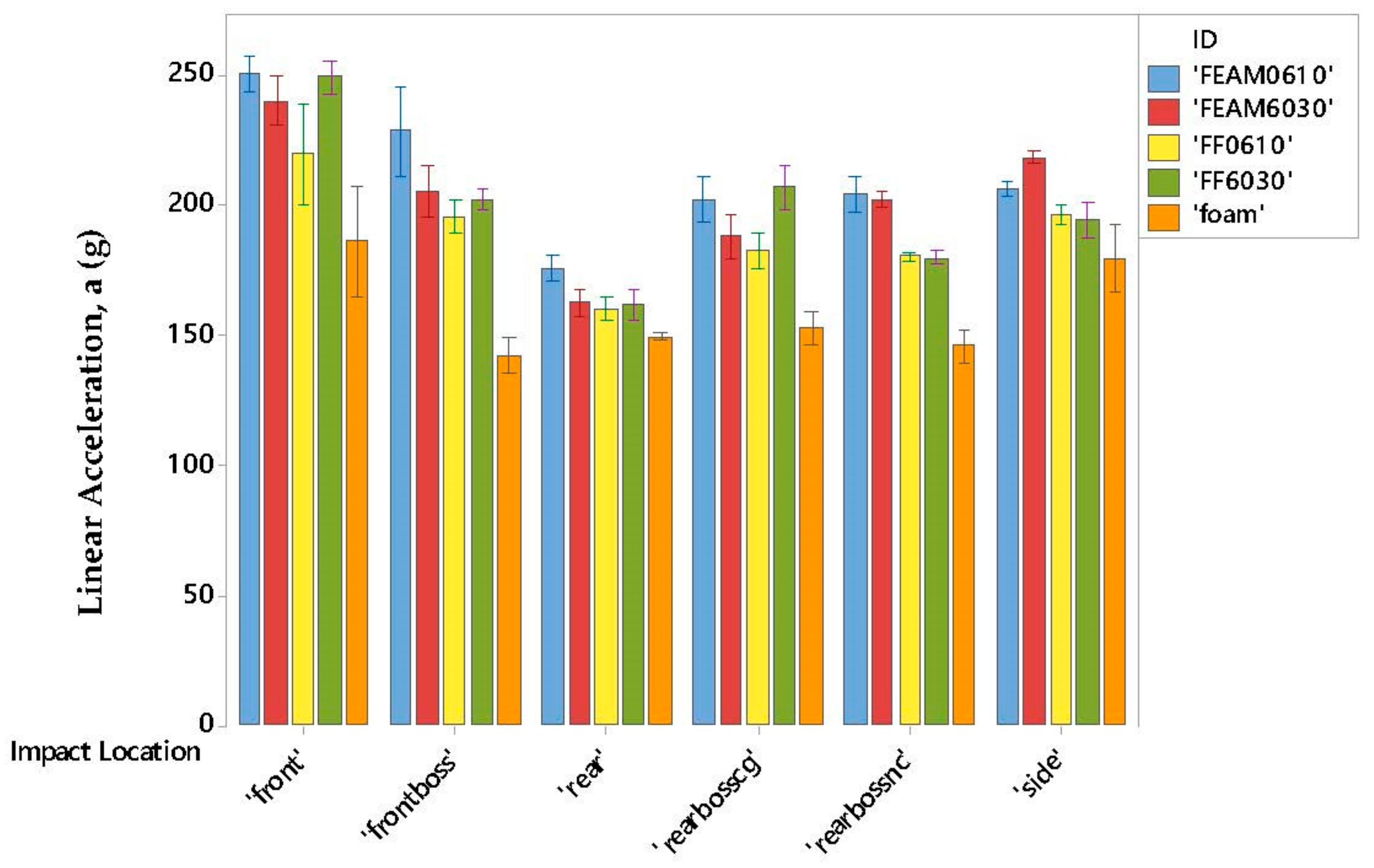
3.4. High Impact Velocity

Figure 14 and Figure 15 show the resultant linear acceleration and resultant angular acceleration for each padding configuration and impact location under high velocity impact conditions (10 m/s). It can be identified that padding performance is highly dependent upon location and padding type. The results for these impacts are representative of the most violent football impacts, sometimes labeled as elite impacts. At these levels, FEAM paddings have a tough time competing with foams. In almost every impact case, and for both metrics, the fiber-based padding underperformed when compared to foam. This is not to say that there is no fiber-based padding that could compete with foam, just that this study was too small in scope to investigate the entire parameter space of the designed paddings.
One promising attribute noticeable from the data are that rotational acceleration for at least one FEAM configuration showed no statistically significant difference when compared to foam impacts as indicated by overlapping error bars. Therefore, the FEAM paddings tend to perform better at lower impact velocities, and at least do not perform worse at higher impact velocities in terms of rotational accelerations. There is one exception which is the rear boss nc impact. At these increased impact velocities, it is believed that the materials behave significantly different than what has been seen in the other tests. The fibers experience dynamic compressive and shear loading simultaneously. In general, an improved performance can be seen for the FEAM6030 when compared with FEAM0610 due to once again to the differing fiber densities. We also tend in general to see the similar trends in the padding materials becoming more like foam, as foam substrates are added with some exceptions.

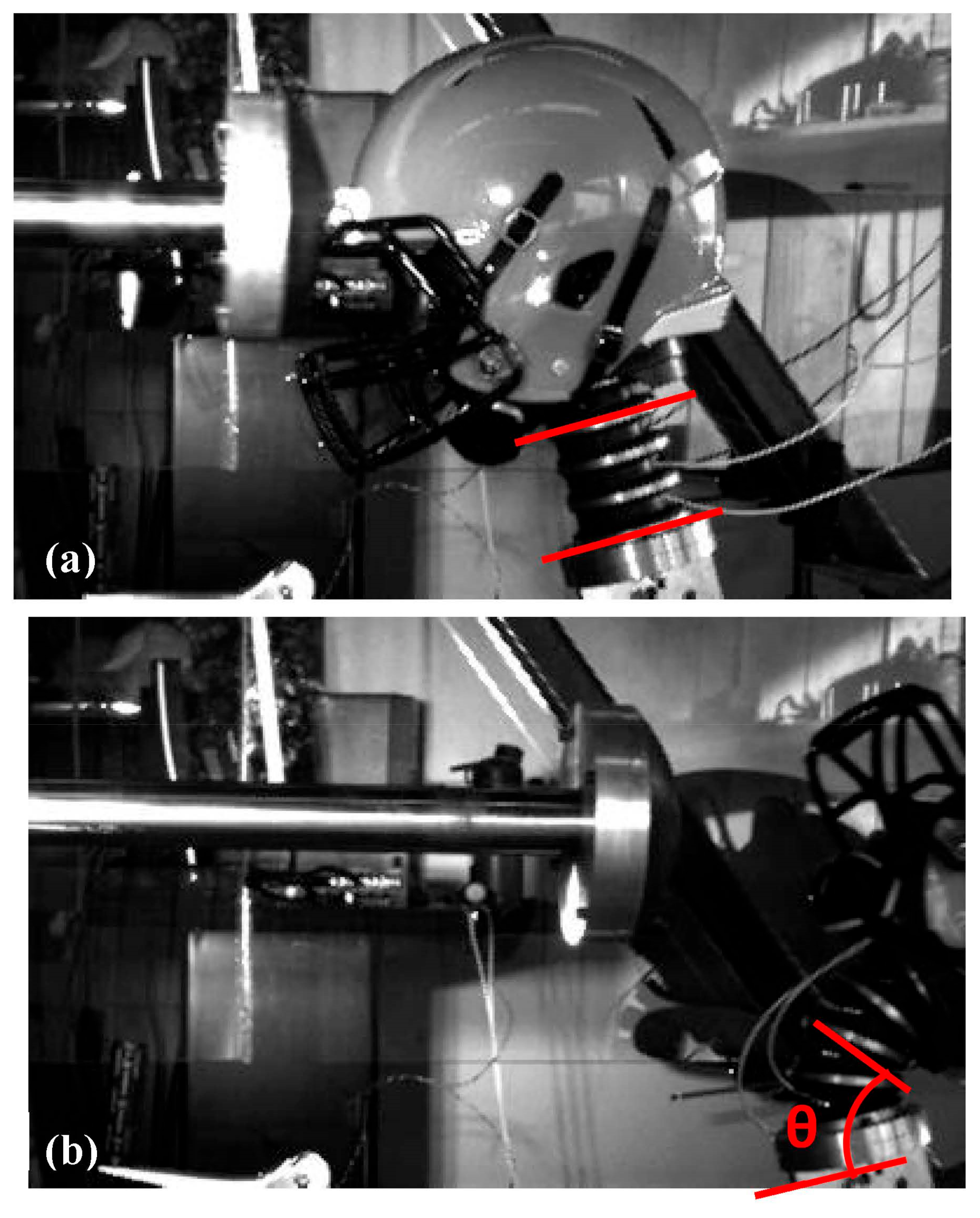
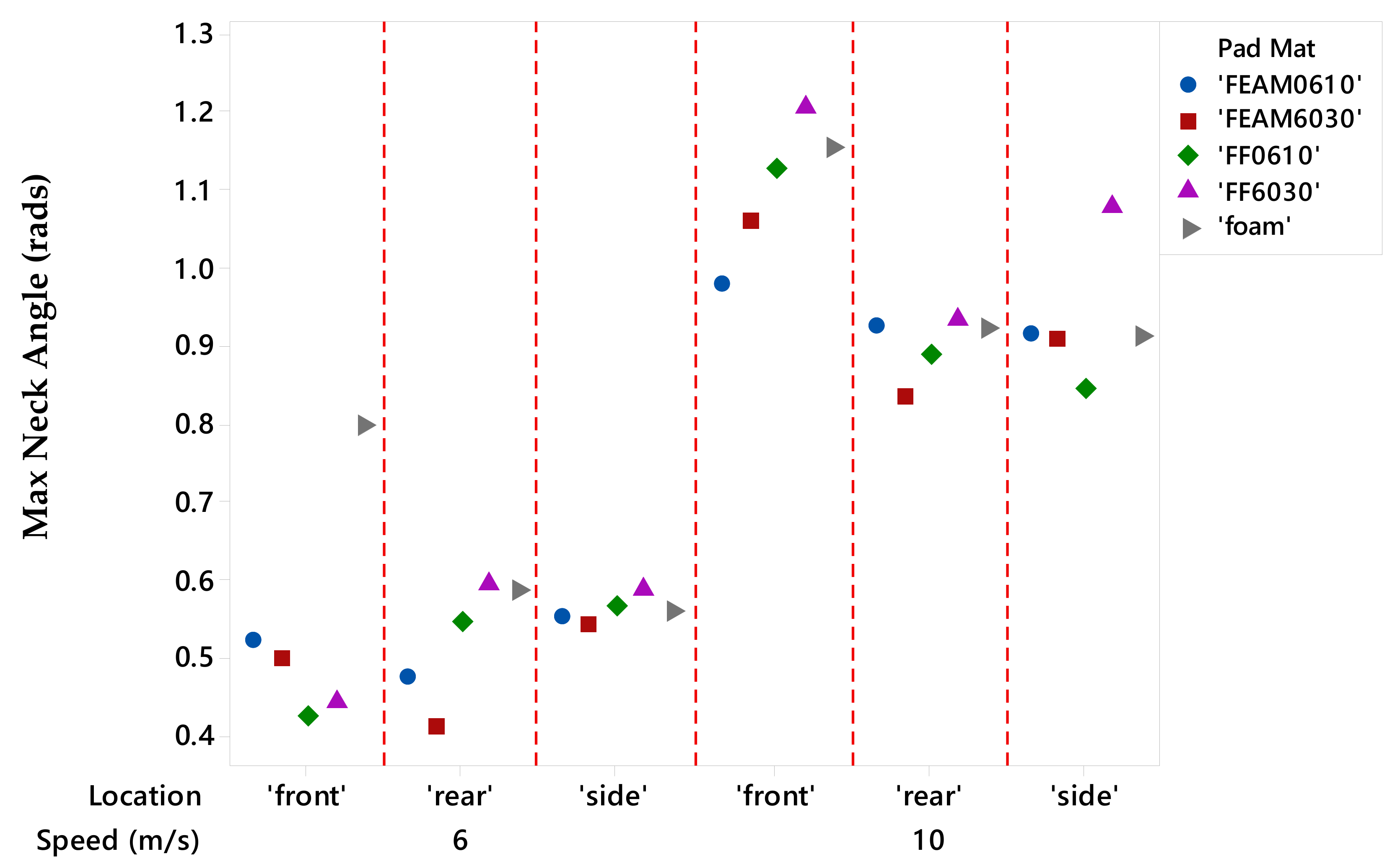
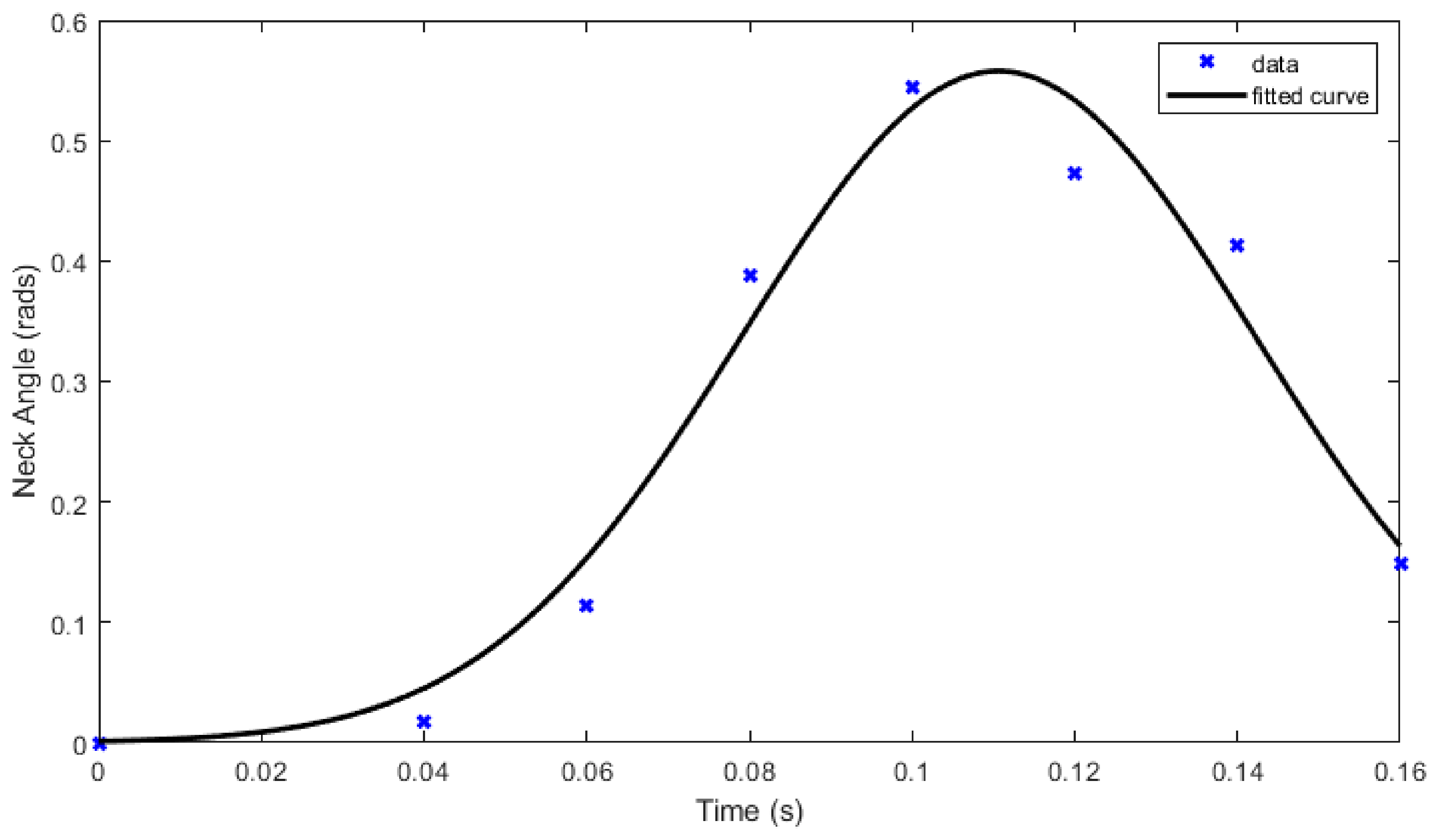
3.5. High Speed Video Neck Flexion Analysis

In order to analyze the neck flexion, some assumptions are made to simplify the calculations. It is assumed that neck flexion occurs continuously through time so that a small subset of frames for each high-speed video may be analyzed. A note of caution in relying on the data presented here is that the head center of gravity cannot be determined as there is some motion of the helmet relative to the head during impacts. The data are therefore collected by measuring the angel of the base of the neck and the most visible vertebrae of the neck. The angle of interest is more thoroughly outlined in Figure 4.
The data are first collected using measuring points from frame-by-frame playbacks of the high-speed video. The initial frame is determined to be when the impactor is just about to hit the helmeted head. The final frame is determined to be when the neck either is about to exit the frame, or the neck returns to its initial angle with respect to the base. The frames are incremented in such a way as to maintain a 0.01 s change in time and was done to ignore any difference in frame rate capturing speed. Once all data are collected it is post-processed via MATLAB using a nonlinear gaussian curve fitting scheme. The gaussian formula as given below is used due to goodness of fit metrics being relatively high for each impact.
θ = a 1 e t b 1 c 1 2
in which θ is the neck flexion angle, t is the time, and a1, b1,and c1 are the determined coefficients of the model. A typical fit is shown in Figure 16.
Once the data are fit using the gaussian, the neck flexion velocity and neck flexion acceleration values are determined through numerical differentiation. After calculating these metrics, the maximum values are determined and graphed on individual value plots to investigate how pad material and impact location affects the neck flexion angle, neck flexion velocity, and neck flexion acceleration. Figure 17, Figure 18 and Figure 19 show the individual value plots of the neck flexion angle, velocity, and acceleration respectively. Under certain circumstances, FEAM padding showed better performance than VN foam. In almost every case, at least one FEAM configuration showed decreased neck flexion angles as compared with foam. The neck flexion velocity was also lower for at least one FEAM configuration compared to the foam samples, except for the front 10 m/s impact. Lastly the most important plot of the neck flexion acceleration showed improvement in at least one FEAM configuration as compared to foam, except for the front 6 m/s impact, and the front 10 m/s impact.
It should be noted that these data are not comparable to any of the current literature as most of the current literature determines the associated metrics at the COG of the NOCSAE head. This data, however, being the first of its kind, may provide some insight into mTBI associated with neck injury such as Brachial Plexus injuries (commonly referred to as a ‘Stinger’) that are outlined and defined rigorously by Daly et al. [41]. It has also been shown by Hrysomallis that neck strength and neck training programs are directly related to neck injury and concussion risk in contact sports [42]. Therefore, it stands to reason that the neck can be tensioned for different real-life scenarios. Although it cannot be changed at any instant, it can be pre-tensioned to replicate different levels of bracing for impact. The importance of neck flexion angle is that it should be directly related to energy absorbed by the helmet. The more energy absorbed by the helmet, the less the neck should bend, given the same neck pre-tensioning. Less neck bending would also help reduce strains induced on the cervical spinal cord which could possibly help reduce risk of injury. In this experiment, it was set according to the standard value of 12 in-lbf (1.344 m-N) as provided by the manufacturer. This, however, may or may not accurately reflect more realistic conditions.

4. Discussion

The data presented above shows that, in some cases, FEAM-type padding materials reduced linear and angular acceleration metrics. Although the impactor should impart the same force for a given impact velocity, different head orientations and impact locations will alter the resultant kinematics. For instance, the stiffness of the neck most likely differs when the head rotates in the coronal plane (ear to shoulder style rotation) as opposed to the sagittal plane (forward to backward style rotation). This may be one reason why the FEAM performed better in certain impact locations when compared with others, and may be most noticeable when looking at front, rear, and side impacts as the rotations occur in only one plane. Essentially, the materials experience different stresses and strains due to anisotropic neck stiffnesses.
The material structures also influence how the metrics change due to different impact positions. FEAMs tend to be inhomogeneous at the micro scale. By nature of flocking, the impregnated flock fibers are not necessarily perpendicular to the substrate. It may be that certain pads have better or worse characteristics due to this inhomogeneity. Pads that have more fibers in line with the direction of impact would have more buckling fibers, leading to increased internal friction, and therefore increased energy dissipation.
The practical connection of this study on players of American football is to identify the optimum combination of FEAM-based padding materials, along with VN foam so that both linear and angular accelerations can be decreased to mitigate the head injuries and concussions of the players during the impact. More studies are needed to have a detailed parametric study that includes different fiber materials, fiber length, fiber diameter, thickness of VN foam, or other foam materials to investigate and optimize various metrics of football impacts. It is, however, promising to see significant reductions in rotational accelerations of the player head with fiber-based padding, especially at the lower impact velocities which are typically more prevalent in American football [43,44,45].

5. Conclusions

An experimental study is conducted to understand the effectiveness of fiber-based energy absorbing materials both on textile fabrics and foams against the VN foam for helmet padding materials under three different impact speeds using a linear impactor in conjunction with high-speed video camera. The following are the major outcomes of the study:
For low velocity impacts, (a) FEAM6030 showed superior performance in angular acceleration compared to all padding materials for all six impact locations, and (b) FEAM6030 also performed relatively well in the linear acceleration either by matching or exceeding foam except for side and front boss impacts.
For medium velocity impacts, (a) FEAM6030 showed superior performance in angular acceleration compared to VN foam for all impact locations except “rear boss cg” and rear boss ng”, and (b) VN foam outperforms in linear acceleration compared to all other padding types for the impact locations except for “front”.
For high velocity impacts, generally, VN foam outperformed for all four measurements of linear acceleration, and angular acceleration for most of the impact locations.
On neck flexion, generally, the neck angle increased by almost twice for all three impact locations when the impact speed increased from 6 m/s to 10 m/s. The maximum neck flexion angle results determined from the high-speed video imaging show that FEAM-based padding materials tend to reduce the maximum neck angle. Maximum neck velocity was also reduced in most impact positions; however, max angular acceleration was only reduced in rear and side impact positions.
Overall, the FEAM-based padding materials demonstrated superior performance to reduce angular or rotational acceleration of head successfully for both low and medium impact speeds. Although FEAM-based padding materials of higher denier fibers showed some promise in matching or exceeding the performance against linear acceleration of VN foam at lower impact speeds, having foam as a substrate in novel FF padding systems showed superior performance compared to FEAM pads. In this study, a very limited parametric space of nylon fibers and polymer substrates is considered. There is a great scope of material selection to further optimize both linear and angular acceleration at all impact speeds including high speed impact of 10 m/s. In addition to understanding the mechanics of fiber deformation under impacts, multi-scale simulations are necessary. The experimental results are limited to macro-scale or global measurement of padding materials performance. The experimental details of this study, such as loading conditions and the acceleration responses, can serve as validating data for developing multi-scale numerical models.

Author Contributions

All authors performed investigation and participated in the writing and the final review. All authors have read and agreed to the published version of the manuscript.

Funding

The authors acknowledge the financial support of DoD-DURIP grant of W911NF-17-1-0192 for acquiring a high-speed video camera.

Data Availability Statement

The data that support the findings of this study are available from the corresponding author upon reasonable request.

Conflicts of Interest

The authors declare no conflict of interest.

References

  1. Ford, J.H.; Giovanello, K.S.; Guskiewicz, K.M. Episodic memory in former professional football players with a history of concussion: An event-related functional neuroimaging study. J. Neurotrauma. 2013, 30, 1683–1701. [Google Scholar] [CrossRef] [PubMed]
  2. Jordan, B.D. The clinical spectrum of sport-related traumatic brain injury. Nat. Rev. Neurol. 2013, 9, 222–230. [Google Scholar] [CrossRef] [PubMed]
  3. Hampshire, A.; MacDonald, A.; Owen, A.M. Hypoconnectivity and hyperfrontality in retired American football players. Sci. Rep. 2013, 3, 2972. [Google Scholar] [CrossRef] [PubMed]
  4. Didehbani, N.; Munro Cullum, C.; Mansinghani, S.; Conover, H.; Hart, J., Jr. Depressive symptoms and concussions in aging retired NFL players. Arch. Clin. Neuropsychol. 2013, 28, 418–424. [Google Scholar] [CrossRef] [PubMed]
  5. Kumar, N.S.; Chin, M.; O’Neill, C.; Jokoi, A.M.; Tabb, L.; Wolf, M. On-field performance of national football league players after return from concussion. Am. J. Sports Med. 2014, 42, 2050–2055. [Google Scholar] [CrossRef] [PubMed]
  6. Clay, M.B.; Glover, K.L.; Lowe, D.T. Epidemiology of concussion in sport: A literature review. J. Chiropr. Med. 2013, 12, 230–251. [Google Scholar] [CrossRef] [PubMed]
  7. McGuine, T.A.; Hetzel, S.; McCrea, M.; Brooks, M.A. Protective equipment and player characteristics associated with the incidence of sport-related concussion in high school football players: A multifactorial prospective study. Am. J. Sports Med. 2014, 42, 2470–2478. [Google Scholar] [CrossRef] [PubMed]
  8. Stein, C.J.; MacDougall, R.; Quatman-Yates, C.C.; Myer, G.D.; Sugimoto, D.; Dennison, R.J.; Meehan, W.P. Young athletes’ concerns about sport-related concussion: The patient’s perspective. Clin. J. Sport Med. 2016, 26, 386–390. [Google Scholar] [CrossRef]
  9. Schneider, D.K.; Grandhi, R.K.; Bansal, P.; Kuntz, G.E.; Webster, K.E.; Logan, K.; Barber, K.D.F.; Myer, G.D. Current state of concussion prevention strategies: A systematic review and meta-analysis of prospective, controlled studies. Br. J. Sports Med. 2017, 51, 1473–1482. [Google Scholar] [CrossRef]
  10. Cecchi, N.J.; Oros, T.J.; Ringhofer, J.J.; Monroe, D.C. Comparison of head impact attenuation capabilities between a standard American football helmet and novel protective equipment that couples a helmet and shoulder pads. Sports Eng. 2019, 22, 16. [Google Scholar] [CrossRef]
  11. Johnston, J.M.; Ning, H.; Kim, J.-E.; Kim, Y.-H.; Soni, B.; Reynolds, R.; Cooper, L.; Andrews, J.B.; Vaidya, U. Simulation, fabrication and impact testing of a novel football helmet padding system that decreases rotational acceleration. Sports Eng. 2015, 18, 11–20. [Google Scholar] [CrossRef]
  12. McElhaney, J.H.; Roberts, V.L.; Hilyard, J.F. Properties of human tissues and components: Nervous tissues. In Handbook of Human Tolerance; Automobile Research Institute Inc.: Tokyo, Japan, 1976; Volume 143. [Google Scholar]
  13. Gennarelli, T.A.; Thibault, L.E.; Ommaya, A.K. Pathophysiological Responses to Rotational and Translational Accelerations of the Head. In Proceedings of the 16th Stapp Car Crash Conference, Detroit, MI, USA, 8–10 November 1972; Society of Automotive Engineers: Warrendale, PA, USA, 1972. [Google Scholar]
  14. Gennarelli, T.A.; Thibault, L.E.; Tomei, G.; Wiser, T.G.; Adams, G.J. Directional Dependence of Axonal Brain Injury due to Centroidal and Non-Centroidal Acceleration. In Proceedings of the 31st Stapp Car Crash Conference, New Orleans, LA, USA, 9–11 November 1987; SAE Technical Paper. p. 872197. [Google Scholar]
  15. Sances, A., Jr.; Herbst, B.; Khadilkar, A.V. Biomechanical Analysis of Padding. In Proceedings of the ASME International Mechanical Engineering Congress and Exposition, Nashville, TN, USA, 14–19 November 1999. [Google Scholar]
  16. Gambel, G.M.; Hoshizaki, T.B. Compressive properties of helmet materials subjected to dynamic impact loading of various energies. Eur. J. Sport. Sci. 2008, 8, 341–349. [Google Scholar] [CrossRef]
  17. Ramirez, B.J.; Gupta, V. Evaluation of novel temperature-stable viscoelastic polyurea foams as helmet liner materials. Mater. Des. 2018, 137, 298–304. [Google Scholar] [CrossRef]
  18. Foster, L.; Peketi, P.; Allen, T.; Senior, T.; Duncan, O.; Alderson, A. Application of Auxetic Foam in Sports Helmets. Appl. Sci. 2018, 8, 354. [Google Scholar] [CrossRef]
  19. Vicis, Inc. 2019. Available online: https://vicis.com/products/zero1 (accessed on 3 December 2019).
  20. Hanna, B.; Adams, R.; Townsend, S.; Robinson, M.; Soe, S.; Stewart, M.; Burek, R.; Theobald, P. Auxetic metamaterial optimisation for head impact mitigation in American football. Int. J. Impact Eng. 2021, 157, 103991. [Google Scholar] [CrossRef]
  21. Sokoloff, J.B. Hydrophilic porous materials as helmet padding able to prevent traumatic brain injuries. J. Appl. Phys. 2022, 132, 125102. [Google Scholar] [CrossRef]
  22. Decker, W.; Baker, A.; Ye, X.; Brown, P.; Stitzel, J.; Gayzik, F.S. Development and Multi-Scale Validation of a Finite Element Football Helmet Model. Ann. Biomed. Eng. 2020, 48, 258–270. [Google Scholar] [CrossRef] [PubMed]
  23. Mills, S.T.; Young, T.S.; Chatham, L.S.; Poddar, S.; Carpenter, R.D.; Yakacki, C.M. Effect of foam densification and impact velocity on the performance of a football helmet using computational modeling. Comput. Methods Biomech. Biomed. Eng. 2021, 24, 21–32. [Google Scholar] [CrossRef]
  24. Cecchi, N.J.; Alizadeh, H.V.; Liu, Y.; Camarillo, D.B. Finite element evaluation of an American football helmet featuring liquid shock absorbers for protecting against concussive and subconcussive head impacts. Front. Bioeng. Biotechnol. 2023, 11, 1160387. [Google Scholar] [CrossRef]
  25. Lewis, A.; Matos, H.; Rice, J.; Kim, Y. Impact force loss behavior of flocked surfaces. Text. Res. J. 2016, 88, 392–412. [Google Scholar] [CrossRef]
  26. Fodor, K.; Chalivendra, V.; Kim, Y.; Lewis, A. Dynamic Mechanical Behavior of Flocked Layer Composite Materials. Compos. Struct. 2018, 207, 677–683. [Google Scholar] [CrossRef]
  27. Kim, Y.K.; Chalivendra, V.B.; Lewis, A.F.; Fasel, B. Designing flocked energy-absorbing material layers into sport and military helmet pads. Text. Res. J. 2022, 92, 15–16. [Google Scholar] [CrossRef]
  28. Correia, J.; Chalivendra, V.; Kim, Y. Parametric study of a fibrous energy absorbing material under impact shear loading. Compos. Struct. 2020, 232, 111583. [Google Scholar] [CrossRef]
  29. Rowson, S.; Duma, S.M.; Beckwith, J.G.; Chu, J.J.; Greenwald, R.M.; Crisco, J.J.; Brolinson, G.P.; Duhaime, A.-C.; McAllister, T.W.; Maerlender, A.C. Rotational head kinematics in football impacts: An injury risk function for concussion. Ann. Biomed. Eng. 2012, 40, 1–13. [Google Scholar] [CrossRef]
  30. Zhang, L.; Yang, K.H.; King, A.I. A Proposed Injury Threshold for Mild Traumatic Brain Injury. J. Biomech. Eng. 2004, 126, 226. [Google Scholar] [CrossRef] [PubMed]
  31. Kimpara, H.; Iwamoto, M. Mild traumatic brain injury predictors based on angular accelerations during impacts. Ann. Biomed. Eng. 2012, 40, 114–126. [Google Scholar] [CrossRef] [PubMed]
  32. Kleiven, S. Evaluation of head injury criteria using a finite element model validated against experiments on localized brain motion, intracerebral acceleration, and intracranial pressure. Int. J. Crashworthiness 2006, 11, 65–79. [Google Scholar] [CrossRef]
  33. Morrison, B.; Sundstrom, L.E.; Ateshian, G.A.; Thomas, F.C.; Cater, H.L.; Hung, C.T.; Ateshian, G.A.; Sundstrom, L.E. A Tissue Level Tolerance Criterion for Living Brain Developed with an In Vitro Model of Traumatic Mechanical Loading. SAE Tech. Pap. Ser. 2018, 1, 93–105. [Google Scholar]
  34. Elkin, B.S.; Morrison, B. Region-specific tolerance criteria for the living brain. Stapp. Car. Crash. J. 2007, 51, 127–138. [Google Scholar]
  35. NOCSAE. Standard Pneumatic Ram Test Method and Equipment Used in Evaluating the Performance Characteristics of Protective Headgear and Face Guards; NOCSAE: Litchfield Park, AZ, USA, 2015; pp. 1–9. [Google Scholar]
  36. Rowson, B.; Rowson, S.; Duma, S.M. Hockey STAR: A Methodology for Assessing the Biomechanical Performance of Hockey Helmets. Ann. Biomed. Eng. 2015, 43, 2429–2443. [Google Scholar] [CrossRef]
  37. Pellman, E.J.; Viano, D.C.; Tucker, A.M.; Casson, I.R.; Waeckerle, J.F. Concussion in Professional Football: Reconstruction of Game Impacts and Injuries. Neurosurgery 2003, 53, 799–814. [Google Scholar] [CrossRef] [PubMed]
  38. Pellman, E.J.; Viano, D.C.; Tucker, A.M.; Casson, I.R. Concussion in Professional Football: Location and Direction of Helmet Impacts—Part 2. Neurosurgery 2003, 53, 1328–1341. [Google Scholar] [CrossRef] [PubMed]
  39. Pellman, E.J.; Viano, D.C.; Withnall, C.; Shewchenko, N.; Bir, C.A.; Halstead, P.D. Concussion in professional football: Helmet testing to assess impact performance—Part 11. Neurosurgery 2006, 58, 78–95. [Google Scholar] [CrossRef] [PubMed]
  40. Jadischke, R. Football Helmet Fitment and its Effects on Helmet Performance. Master’s Thesis, Wayne State University, Detroit, MI, USA, 2012. [Google Scholar]
  41. Daly, C.A.; Payne, S.H.; Seiler, J.G. Severe Brachial Plexus Injuries in American Football. Orthopedics. 2016, 39, e1188–e1192. [Google Scholar] [CrossRef] [PubMed]
  42. Hrysomallis, C. Neck Muscular Strength, Training, Performance and Sport Injury Risk: A Review. Sports Med. 2016, 46, 1111–1124. [Google Scholar] [CrossRef]
  43. Bailey, A.; Funk, J.; Lessley, D.; Sherwood, C.; Crandall, J.; Neale, W.; Rose, N. Validation of a videogrammetry technique for analysing American football helmet kinematics. Sports Biomech. 2020, 19, 678–700. [Google Scholar] [CrossRef] [PubMed]
  44. Bailey, A.M.; Sherwood, C.P.; Funk, J.R.; Crandall, J.R.; Carter, N.; Hessel, D.; Beier, S.; Neale, W. Characterization of Concussive Events in Professional American Football Using Videogrammetry. Ann. Biomed. Eng. 2020, 48, 2678–2690. [Google Scholar] [CrossRef] [PubMed]
  45. Camarillo, D.B.; Shull, P.B.; Mattson, J.; Shultz, R.; Garza, D. An Instrumented Mouthguard for Measuring Linear and Angular Head Impact Kinematics in American Football. Ann. Biomed. Eng. 2013, 41, 1939–1949. [Google Scholar] [CrossRef]
Figure 1. Schematic of electro-static up-flocking process.
Fibers 11 00096 g001
Figure 2. Schematic of fabrication process for creating FEAM padding materials, where the red arrow indicates the rolling direction.
Fibers 11 00096 g002
Figure 3. Pendulum based linear impactor with a magnesium head.
Fibers 11 00096 g003
Figure 4. Typical resultant angular velocity of an impact (a) raw collected data and (b) filtered data.
Fibers 11 00096 g004
Figure 5. Images of high-speed camera, with outlines of how neck flexion angle is calculated for each frame. (a) shows the neck flexion angel of 0° when impact first starts, while (b) shows the neck flexion angle θ for any time during and after impact.
Fibers 11 00096 g005
Figure 6. Optical images of microstructure of FEAM padding materials: (a) FEAM0610, (b) FEAM6030, (c) FF0610, and (d) FF6030.
Fibers 11 00096 g006
Figure 7. Helmet impact locations superimposed upon the helmeted CAD model.
Fibers 11 00096 g007
Figure 8. The average of resultant linear accelerations for all impact locations grouped by impact velocity and comparing the control versus foam configurations.
Fibers 11 00096 g008
Figure 9. The average of resultant angular accelerations for all impact locations grouped by impact velocity and comparing the control versus foam configurations.
Fibers 11 00096 g009
Figure 10. The average resultant linear acceleration grouped by padding type and impact location for the 6 m/s impact velocity.
Fibers 11 00096 g010
Figure 11. The average resultant angular acceleration grouped by padding type and impact location for the 6 m/s impact velocity.
Fibers 11 00096 g011
Figure 12. The average resultant linear acceleration grouped by padding type and impact location for the 8 m/s impact velocity.
Fibers 11 00096 g012
Figure 13. The average resultant angular acceleration grouped by padding type and impact location for the 8 m/s impact velocity.
Fibers 11 00096 g013
Figure 14. The average resultant linear acceleration grouped by padding type and impact location for the 10 m/s impact velocity.
Fibers 11 00096 g014
Figure 15. The average resultant angular acceleration grouped by padding type and impact location for the 10 m/s impact velocity.
Fibers 11 00096 g015
Figure 16. Characteristic plot of the Gaussian fit used to analyze neck flexion angle data recorded from high-speed images.
Fibers 11 00096 g016
Figure 17. Max neck angle grouped by padding type, impact location, and impact speed.
Fibers 11 00096 g017
Figure 18. Max neck angular velocity grouped by padding type, impact location, and impact speed.
Fibers 11 00096 g018
Figure 19. Max neck angular acceleration grouped by padding type, impact location, and impact speed.
Fibers 11 00096 g019
Table 1. Padding configuration dimensional data and bulk material density.
Padding
ID
Area (cm2)Weight
(g)
Thickness (mm)Thickness DeviationDensity (kg/m3)Areal Density
(kg/m2)
Flock Density (Fibers/mm2)
Foam692.92221.5025.063.87127.583.20NA
FEAM0610659.82423.4021.590.33297.166.42237.44
FEAM6030635.77384.3025.050.30241.306.0421.69
FF0610662.95326.3522.070.87223.034.92234.44
FF6030654.18345.2022.640.53233.035.2819.16
Table 2. FEAM Padding Constituents fractions.
FEAM TypeFlock Mass FractionSubstrate Mass FractionFlock Volume FractionSubstrate Volume FractionVoid Fraction
FEAM061044.71%55.29%10.89%33.95%55.16%
FEAM603059.35%40.65%13.78%23.81%62.41%
FF061042.06%57.94%6.85%82.64%10.51%
FF603057.65%42.35%11.23%72.30%16.48%
Disclaimer/Publisher’s Note: The statements, opinions and data contained in all publications are solely those of the individual author(s) and contributor(s) and not of MDPI and/or the editor(s). MDPI and/or the editor(s) disclaim responsibility for any injury to people or property resulting from any ideas, methods, instructions or products referred to in the content.

