

Multimode Ytterbium–Aluminosilicate Core Optical Fibre for Amplification and Laser Applications


Abstract
:
1. Introduction
2. Materials and Methods
2.1. Preform and Fibre Fabrication
2.2. Characterisation Methods
3. Results
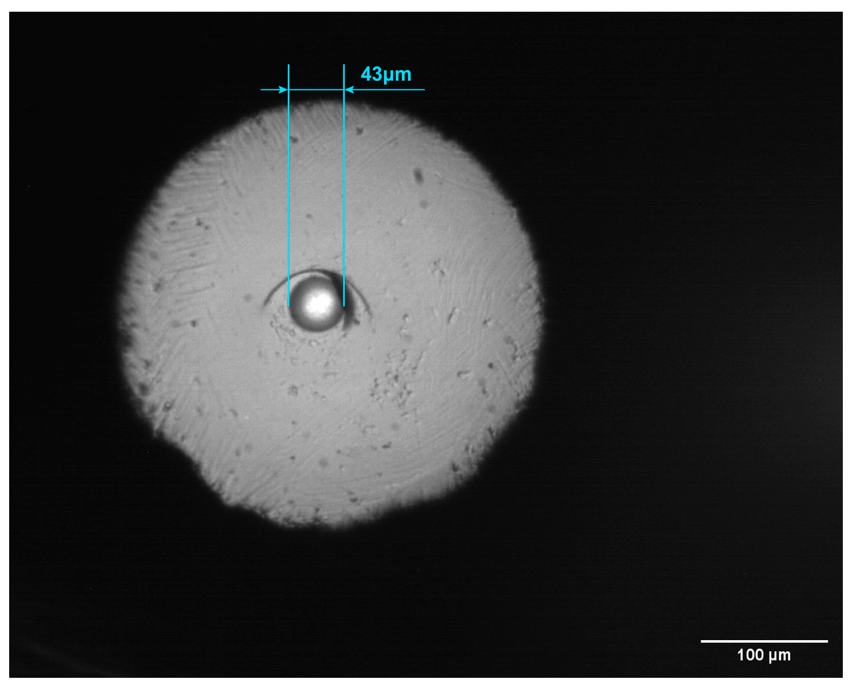
3.1. Micrograph
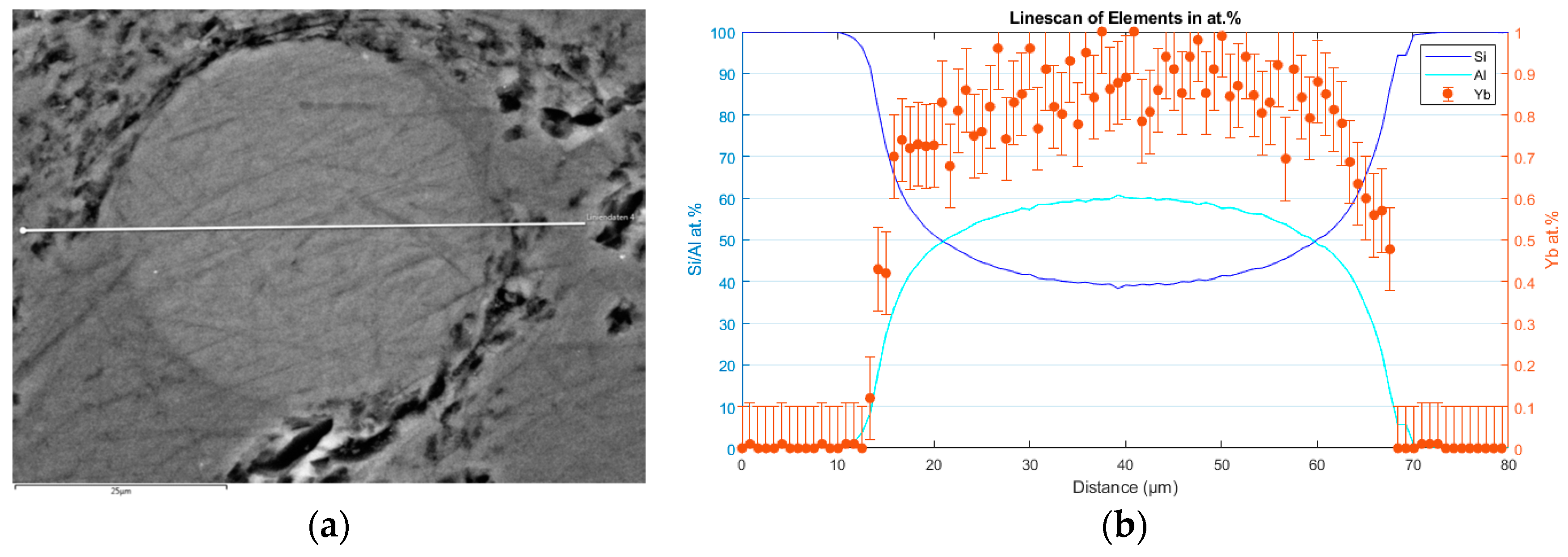
3.2. Energy Dispersive X-ray Analysis
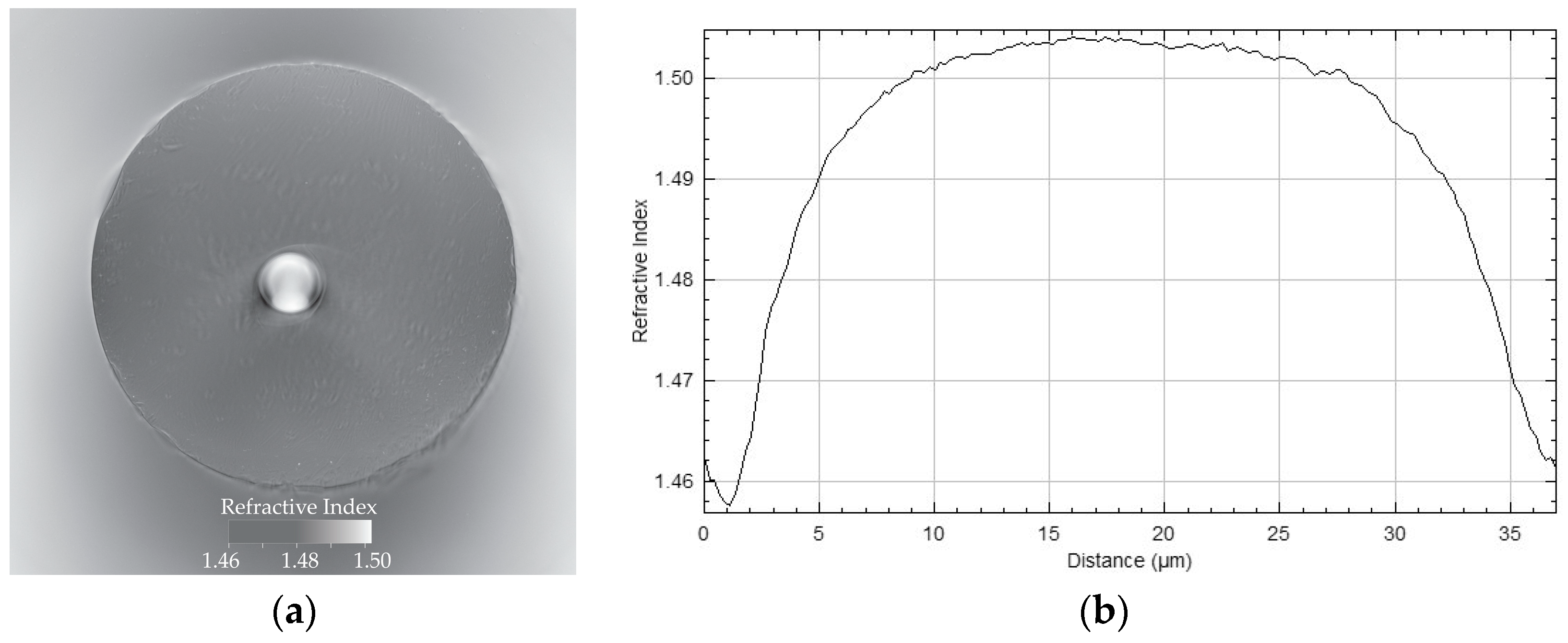
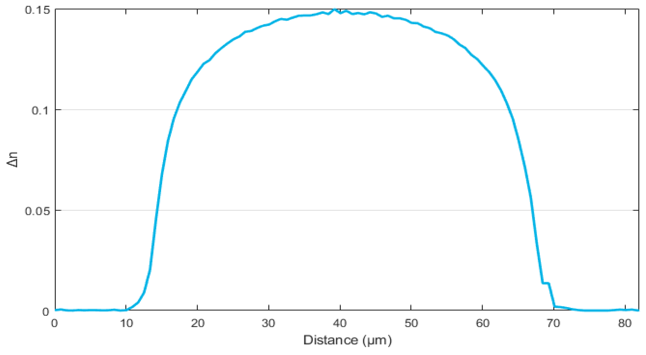
3.3. Refractive Index
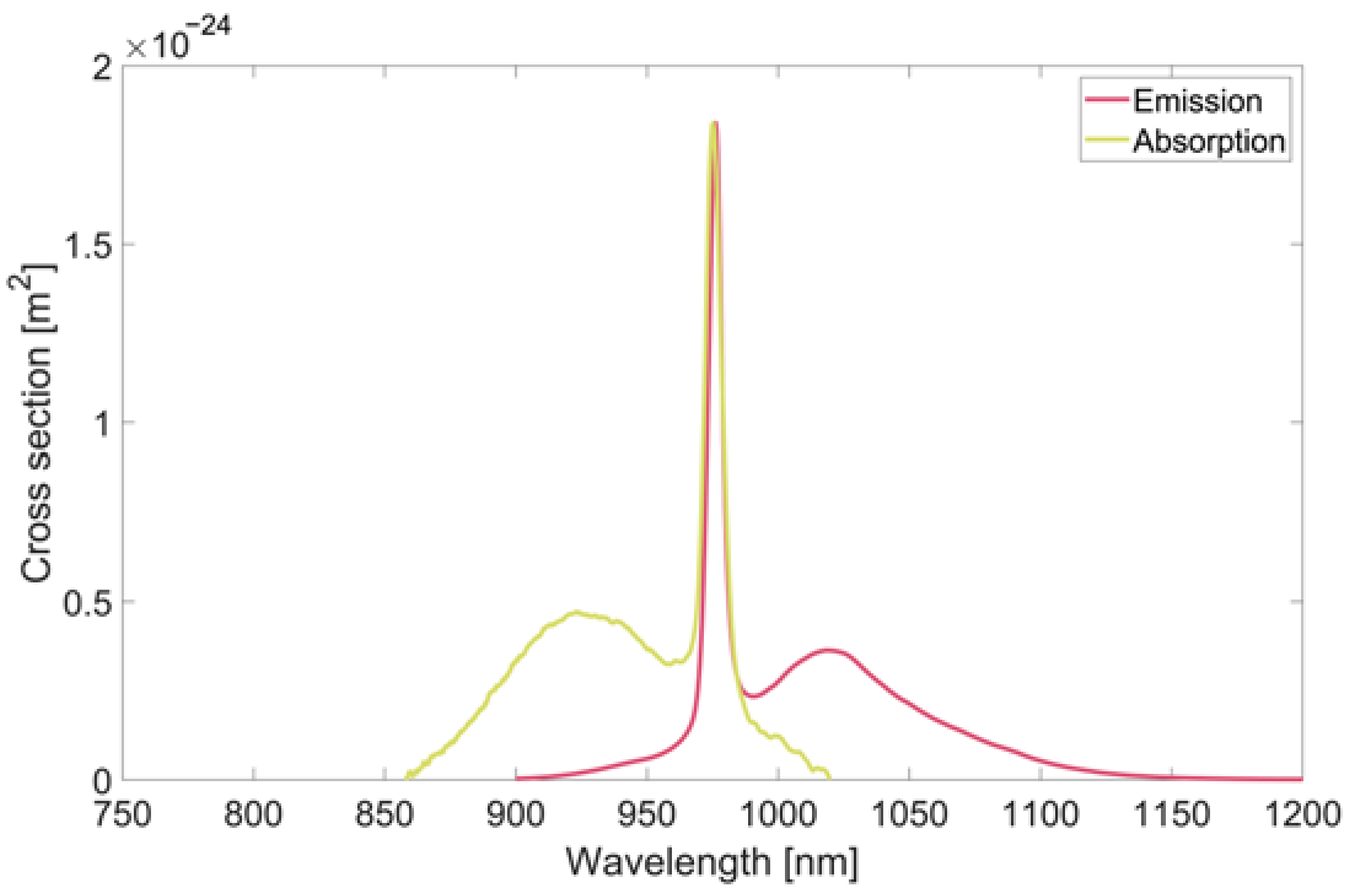
3.4. Fluorescence and Spectroscopy
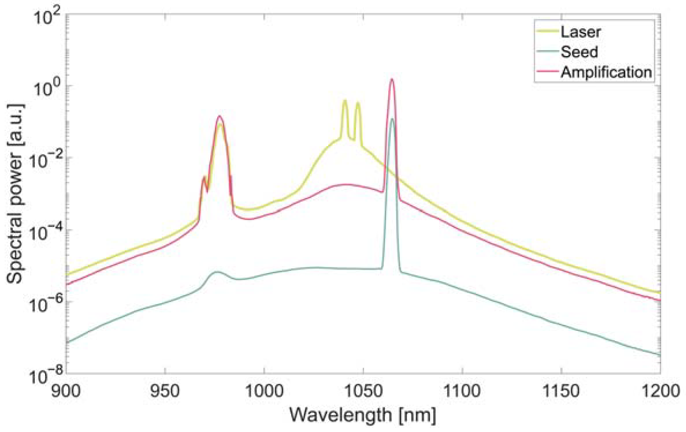
3.5. Signal Amplification and Laser Operation
4. Discussion and Conclusions
Author Contributions
Funding
Data Availability Statement
Acknowledgments
Conflicts of Interest
References
- Bobkov, K.K.; Mikhailov, E.K.; Zaushitsyna, T.S.; Rybaltovsky, A.A.; Aleshkina, S.S.; Melkumov, M.; Bubnov, M.M.; Lipatov, D.S.; Yashkov, M.V.; Abramov, A.N.; et al. Properties of Silica Based Optical Fibres Doped with an Ultra-High Ytterbium Concentration. J. Light. Technol. 2022, 40, 6230–6239. [Google Scholar] [CrossRef]
- Kenyon, A.J. Recent developments in rare-earth doped materials for optoelectronics. Prog. Quantum Electron. 2002, 26, 225–284. [Google Scholar] [CrossRef]
- Podrazky, O.; Kasik, I.; Pospisilova, M.; Matejec, V. Use of alumina nanoparticles for preparation of erbium-doped fibres. In Proceedings of the IEEE Lasers and Electro-Optics Society Annual Meeting Conference Proceedings, Lake Buena Vista, FL, USA, 21–25 October 2007; pp. 246–247. [Google Scholar]
- Renner-Erny, R.; Di Labio, L.; Lüthy, W. A novel technique for active fibre production. Opt. Mater. 2007, 29, 919–922. [Google Scholar] [CrossRef]
- Dhar, A.; Paul, M.C.; Pal, M.; Mondal, A.K.; Sen, S.; Maiti, H.S.; Sen, R. Characterization of porous core layer for controlling rare earth incorporation in optical fibre. Opt. Express 2006, 14, 9006–9015. [Google Scholar] [CrossRef] [PubMed]
- Webb, A.S.; Boyland, A.J.; Standish, R.J.; Yoo, S.; Sahu, J.K.; Payne, D.N. MCVD in-situ solution doping process for the fabrication of complex design large core rare-earth doped fibres. J. Non-Cryst. Solids 2010, 356, 848–851. [Google Scholar] [CrossRef]
- Lindner, F.; Aichele, C.; Schwuchwo, A.; Leich, M.; Scheffel, A.; Unger, S. Optical properties of Yb-doped fibres prepared by gas phase doping. In Proceedings of the SPIE 8982, Optical Components and Materials XI, San Francisco, CA, USA, 1–6 February 2014. 89820R. [Google Scholar]
- Honzatko, P.; Dhar, A.; Kasik, I.; Podrazky, O.; Matejec, V.; Peterka, P.; Blanc, W.; Dussardier, B. Preparation and characterization of highly thulium- and alumina-doped optical fibres for single-frequency fibre lasers. In Proceedings of the SPIE 8306, Photonics, Devices, and Systems V, Prague, Czech Republic, 24–26 August 2011; p. 830608. [Google Scholar]
- Pilz, S.; Najafi, H.; Ryser, M.; Romano, V. Granulated Silica Method for the Fibre Preform Production. Fibres 2017, 5, 24. [Google Scholar] [CrossRef]
- El Sayed, A.; Pilz, S.; Najafi, H.; Alexander, D.T.L.; Hochstrasser, M.; Romano, V. Fabrication and Characteristics of Yb-Doped Silica Fibres Produced by the Sol-Gel Based Granulated Silica Method. Fibres 2018, 6, 82. [Google Scholar] [CrossRef]
- Leich, M.; Just, F.; Langner, A.; Such, M.; Schötz, G.; Eschrich, T.; Grimm, S. Highly efficient Yb-doped silica fibres prepared by powder sinter technology. Opt. Lett. 2011, 36, 1557–1559. [Google Scholar] [CrossRef] [PubMed]
- Leich, M.; Jäger, M.; Grimm, S.; Hoh, D.; Jetschke, S.; Becker, M.; Bartelt, A.H.H. Tapered large-core 976 nm Yb-doped fibre laser with 10 W output power. Laser Phys. Lett. 2014, 11, 045102. [Google Scholar] [CrossRef]
- Unger, S.; Lindner, F.; Aichele, C.; Leich, M.; Schwuchow, A.; Kobelke, J.; Dellith, J.; Schuster, K.; Bartelt, H. A highly efficient Yb-doped silica laser fibre prepared by gas phase doping technology. Laser Phys. 2014, 24, 035103. [Google Scholar] [CrossRef]
- Velmiskin, V.V.; Egorova, O.N.; Mishkin, V.; Nishchev, K.N.; Semjonov, S. Active material for fibre core made by powder-in-tube method: Subsequent homogenization by means of stack-and-draw technique. In Proceedings of the SPIE 8426, Microstructured and Specialty Optical Fibres, Brussels, Belgium, 16–19 April 2012; p. 84260I. [Google Scholar]
- Ye, C.; Petit, L.; Koponen, J.; Hu, I.-N.; Galvanauskas, A. Short-Term and Long-Term Stability in Ytterbium-Doped High-Power Fibre Lasers and Amplifiers. IEEE—Sel. Top. Quantum Electron. 2014, 20, 188–199. [Google Scholar]
- He, W.; Leich, M.; Grimm, S.; Kobelk, J.; Zhu, Y.; Bartelt, H.; Jäger, M. Very large mode area ytterbium fibre amplifier with aluminum-doped pump cladding made by powder sinter technology. Laser Phys. Lett. 2015, 12, 015103. [Google Scholar] [CrossRef]
- Blaser, D.; Pilz, S.; Pedrido, C.; Romano, V. High alumina content optical fibres by powder methods. In Proceedings of the SPIE 12140, Micro-Structured and Specialty Optical Fibres VII, Strasbourg, France, 3 April–23 May 2022; p. 1214008. [Google Scholar]
- Romano, V.; Pilz, S.; Najafi, H. Powder Process for fabrication of Rare Earth-Doped Fibers for Lasers and Amplifiers. In Handbook of Optical Fibers (S. 1-43); Springer Nature: Singapore, 2018. [Google Scholar] [CrossRef]
- Devautour, M.; Roy, P.; Février, S.; Pedrido, C.; Sandoz, F.; Romano, V. Nonchemical-vapor-deposition process for fabrication of highly efficient Yb-doped large core fibres. Appl. Opt. 2009, 48, G139–G142. [Google Scholar] [CrossRef] [PubMed]
- Blomquist, R.A.; Fink, J.K.; Leibowitz, L. Viscosity of Molten Alumina; Argonne National Laboratory: Lemont, IL, USA, 1978.
- El Sayed, A.; Pilz, S.; Ryser, M.; Romano, V. Two-dimensional refractive index profiling of optical fibres by modified refractive near-field technique. In Proceedings of the SPIE 9744, Optical Components and Materials XIII, San Francisco, CA, USA, 13–18 February 2016; p. 97440N. [Google Scholar]
- Filmetrics. Available online: https://www.filmetrics.com/refractive-index-database/Al2O3 (accessed on 8 June 2023).
- Medenbach, O.; Dettmar, D.; Shannon, R.D.; Fischer, R.X.; Yen, W.M. Refractive index and optical dispersion of rare earth oxides using a small-prism technique. J. Opt. A Pure Appl. Opt. 2001, 3, 174. [Google Scholar] [CrossRef]
- Malitson, I.H. Interspecimen Comparison of the Refractive Index of Fused Silica. J. Opt. Soc. Am. 1965, 55, 1205–1208. [Google Scholar] [CrossRef]
- Paschotta, R.; Nilsson, J.; Tropper, A.C.; Hanna, D.C. Ytterbium-doped fibre amplifiers. IEEE J. Quantum Electron. 1997, 33, 1049–1056. [Google Scholar] [CrossRef]
- Barnes, W.L.; Laming, R.I.; Morkel, P.R.; Tarbox, E.J. Absorption-emission cross-section ratio for Er3+ doped fibre at 1.5 μm. In Proceedings of the Lasers and Electro-Optics Conference, Anaheim, CA, USA, 21–25 May 1990; Optica Publishing Group: Washington, DC, USA; p. JTUA3. [Google Scholar]
- Zimer, H.; Kozak, M.; Liem, A.; Flohrer, F.; Doerfel, F.; Riedel, P.; Linke, S.; Horley, R.; Ghiringhelli, F.; Desmoulins, S.; et al. Fibres and fibre-optic components for high-power fibre lasers. In Proceedings of the SPIE 7914, Fiber Lasers VIII: Technology, Systems, and Applications, San Francisco, CA, USA, 22–27 January 2011; p. 791414. [Google Scholar]
- Kirchhof, J.; Unger, S.; Schwuchow, A.; Jetschke, S.; Knappe, B. Dopant Interactions in High-Power Laser Fibres. In Proceedings of the SPIE 5723, Optical Components and Materials II, San Jose, CA, USA, 22–27 January 2005; pp. 261–272. [Google Scholar]
Disclaimer/Publisher’s Note: The statements, opinions and data contained in all publications are solely those of the individual author(s) and contributor(s) and not of MDPI and/or the editor(s). MDPI and/or the editor(s) disclaim responsibility for any injury to people or property resulting from any ideas, methods, instructions or products referred to in the content. |
© 2023 by the authors. Licensee MDPI, Basel, Switzerland. This article is an open access article distributed under the terms and conditions of the Creative Commons Attribution (CC BY) license (https://creativecommons.org/licenses/by/4.0/).
Share and Cite
Blaser, D.; Hänzi, P.; Pilz, S.; Heidt, A.; Romano, V. Multimode Ytterbium–Aluminosilicate Core Optical Fibre for Amplification and Laser Applications. Fibers 2023, 11, 95. https://doi.org/10.3390/fib11110095
Blaser D, Hänzi P, Pilz S, Heidt A, Romano V. Multimode Ytterbium–Aluminosilicate Core Optical Fibre for Amplification and Laser Applications. Fibers. 2023; 11(11):95. https://doi.org/10.3390/fib11110095
Chicago/Turabian StyleBlaser, Dunia, Pascal Hänzi, Sönke Pilz, Alexander Heidt, and Valerio Romano. 2023. "Multimode Ytterbium–Aluminosilicate Core Optical Fibre for Amplification and Laser Applications" Fibers 11, no. 11: 95. https://doi.org/10.3390/fib11110095
APA StyleBlaser, D., Hänzi, P., Pilz, S., Heidt, A., & Romano, V. (2023). Multimode Ytterbium–Aluminosilicate Core Optical Fibre for Amplification and Laser Applications. Fibers, 11(11), 95. https://doi.org/10.3390/fib11110095