

Investigating the Mechanical Performance on Static and Shock Wave Loading of Aramid Fiber-Reinforced Concrete
by
 , ,
, ,
Yeou-Fong Li
1,* ,
,
Hsin-Fu Wang
1,
Jin-Yuan Syu
1,
Gobinathan Kadagathur Ramanathan
1 and
Ying-Kuan Tsai
2 1
Department of Civil Engineering, National Taipei University of Technology, Taipei 10608, Taiwan
2
Department of Environmental Information and Engineering, Chung Cheng Institute of Technology, National Defense University, Taoyuan 33551, Taiwan
*
Author to whom correspondence should be addressed.
Fibers 2022, 10(10), 82; https://doi.org/10.3390/fib10100082
Submission received: 12 July 2022
/
Revised: 21 September 2022
/
Accepted: 22 September 2022
/
Published: 26 September 2022
(This article belongs to the Special Issue Fibers in Concrete Construction: Material Behavior, Design and Strengthening)
Abstract
:Fiber-reinforced concrete (FRC) has been used for over a century to improve the mechanical properties of concrete. Kevlar ® 29 fiber (KF) is one of the most popular aramid fibers used in industrial products. This research investigated the effect of the fiber length, the weight ratio of fiber to cement, the mix-proportion of two fiber lengths, and the sizing on the fiber surface on the mechanical properties of Kevlar fiber-reinforced concrete (KFRC) under static, dynamic, and shock wave loadings. Two lengths of chopped KF and three different weight ratios of fiber to cement were mixed in the KFRC specimens for comparison. Moreover, this study also compared how the five mix-proportions of two fiber lengths affected the mechanical properties of mix-proportion KFRC. KF was dispersed by the pneumatic method first, and then, the separated KF was mixed into the concrete to make KFRC. The results indicated that the KFRC specimens with a 10‰ weight ratio of fiber to cement exhibited the maximum compressive, flexural, and splitting tensile strengths, regardless of whether the fiber length was 12 mm or 24 mm. The main finding showed that the specimen mixed with 24 mm KF could endure the highest impact resistance under different impact energies. From the shock wave test, the external damage on the front and rear faces of all KFRC slabs and the KFRC slab reinforced with two layers of KF sheets was less than that of the benchmark slab. The testing results showed that KF greatly enhanced the static and dynamic mechanical performances of concrete, and the KFRC specimen with a 10‰ weight ratio and 24 mm length KF with sizing exhibited the best performance.
1. Introduction
Concrete is widely used as a material in buildings and infrastructures due to its low price, simple production methods, and its suitability for various environments. However, concrete is brittle for its poor tensile strength. Under an applied external load, concrete tends to crack or peel, often leaving the steel reinforcements exposed to corrosion. These problems greatly reduce the strength and service life of the concrete.
Fiber-reinforced concrete (FRC) is used in specific construction environments due to its outstanding mechanical properties. Adding fiber can enhance the fracture toughness of concrete while reducing the effects of shrinkage. Steel, glass, carbon, aramid, basalt, and polypropylene fibers are commonly used in FRC structures [1,2,3,4,5,6,7]. Compared with glass and polypropylene fibers, steel fiber provides concrete with a higher elastic modulus and tensile strength; however, they are difficult to be distributed uniformly in concrete [8,9]. Silica fume is mixed with steel fiber to improve impact resistance and flexural strength [10,11]. Polypropylene fiber is also combined with steel fiber to reduce crack propagation [12]. The mechanical strength of the FRC mixed with carbon/aramid hybrid fiber is greater than that of the FRC with carbon fiber only [13]. Glass fiber-reinforced polymer (GFRP) is lightweight, strong and resistant to corrosion; however, it is difficult to be recycled. The incorporation of recycled GFRP into concrete can improve the compressive and flexural strength of concrete [14,15,16], while improving impact resistance and alleviating crack propagation [10].
Carbon fiber has the characteristics of high strength, lightweight, and strong fatigue resistance, and it is non-corrosive. The flexural strength, compressive strength, and impact resistance of concrete could be enhanced by adding recycled carbon fiber-reinforced polymer (CFRP) pieces [17,18,19,20,21]. Adding 3% by weight of recycled CFRP pieces into mortar can improve the compressive strength by 21.9% [22]. However, carbon fiber reduces the workability of the concrete mixture and could cause an increase in void content in the specimens, which may reduce the strength [23,24,25,26]. When silane sizing from carbon fiber is removed by using chemical and physical approaches, the mechanical strength of carbon fiber-reinforced concrete (CFRC) is increased compared with that of CFRC that has silane on the surface of the carbon fiber [27]. Incorporating carbon fiber into concrete can effectively inhibit the development of cracks [28]. For this investigation, the carbon fiber was dispersed by injecting the nozzle technique into the cement paste which leads to unidirectional alignment [29]. The hydroxyethyl cellulose process aids the dispersion of carbon fibers, and the maximum dispersion coefficients are 84–94% [30,31].
Aramid fibers have the properties of being lightweight and having high tensile strength, and they can be resistant to abrasion and organic solvents. After the fire resistance test, the compressive strength was increased by about 150% due to the presence of aramid fibers [32]. The compressive strength of aramid FRC with a 1% fiber content exhibited the highest strength, and it had a tendency to decline as the percentage of fiber content increased [33].
The inclusion of fibers can greatly inhibit concrete shrinkage and improve resistance to cracking [1]. These mixes are particularly well suited to rigid pavements, bridge decks, expansion joints, and other concrete components subject to repeated impact by external loadings. Fiber-reinforced concrete can improve resistance to detonation waves in applications such as air defense shelters. Table 1 lists the material properties of various popular fibers [34,35]. As illustrated in Table 1, carbon fiber and aramid fiber have higher strength than other fibers, and they have exceptional weather resistance. As with other fibers, glass fiber is the weakest of not being alkali-resistant, steel fiber is susceptible to rusting, and polypropylene lacks the strength. In addition to fiber strength, fiber elongation is also an important factor to be considered in fiber-reinforced concrete. Therefore, since the elongation at break of aramid fiber is significantly higher than that of carbon fiber, this study used aramid fiber for further mechanical testing.
There are limited studies conducted on the mechanical properties of Kevlar fiber-reinforced concrete (KFRC) under different loading regimes. This study aimed to expand knowledge on the mechanical performance of KFRC from quasi-static to impulsive domains and conducted a series of field explosion tests on the blast resistance of KFRC slabs for validation.
In this study, aramid fiber (Kevlar® 29 fiber, KF) was chopped into two lengths of 12 mm and 24 mm pieces, and part of the original KF was soaked in a toluene solvent to remove the sizing. The original KF and the sizing-removed KF were dispersed by using a pneumatic process first and then mixed with cement, aggregate, and water to make KFRC specimens in different proportions. The workability, compressive strength, flexural strength, splitting tensile strength, impact resistance, and shock wave resistance of KFRC specimens with different weight ratios of fiber to cement and mixed proportions of different fiber lengths were measured to find the best proportion.
2. Materials
In this study, KFRC specimens were prepared for testing, and the materials included chopped aramid fiber, cement, and aggregate. The preparations of KFRC specimens are illustrated as follows.
2.1. Kevlar Fiber (KF)
Kevlar® 29 is an organically synthesized aramid fiber with the monomer formula of −[−CO−C6H4−CONH−C6H4−NH−]−, and it was obtained from DuPont Company. KF is used in military equipment, automated parts, ship ropes, fire-resistant clothing, and vehicle tire reinforcement materials for its high strength, high modulus, low density, and excellent abrasion resistance. Moreover, KF can stand heat less than 450 °C for a few minutes and also resist most of the chemicals such as acetic acid, hydrochloric acid, and other solvents [36]. Table 2 shows the material properties of KF [37]. Figure 1 shows two paths of the fiber pretreatment methods; in the first path, the original KF is dispersed by the pneumatic dispersion process only. In the second path, the sizing of KF is removed by the toluene solvent and then by the drying process and the pneumatic dispersion process. In the following sections, the above original KF and the sizing-removed KF were named K and AK, respectively.
2.2. Cement and Aggregate
In this study, the Portland cement Type I was used, and it was obtained from Taiwan Cement Corporation (Taipei, Taiwan). According to ASTM C33/C33M–18 [38], the fineness modulus (F.M.) of fine aggregates is 3.03; and that of coarse aggregates is 7.33. The fineness modulus of aggregates was 5.96, as listed in Table 3.
2.3. Kevlar Fiber-Reinforced Concrete (KFRC)
The dispersed KF was added to cement and mixed in the dry state to facilitate a uniform distribution. The KFRC specimen was prepared by mixing the KF/cement, aggregate, and water in the wet state, and all specimens were cured for 28 days. The control variables of single-length KFRC preparation included the lengths of chopped KF (12 mm and 24 mm), the KF-to-cement weight ratios (5‰, 10‰, and 15‰), and two types of chopped KF (K and AK). The mixing ratio of cement, sand, and aggregate in concrete was 1:1.05:2.25, and the water−cement ratio of concrete was 0.6.
Based on the mechanical test, the above single-length KFRC specimens were used to decide the best weight ratio of KF to cement for the preparation of mix-proportion KFRC specimens. The mix-proportion KFRC specimens were prepared by mixing two KF lengths (12 mm/24 mm) in ratios of 80–20% (M8/2), 60–40% (M6/4), 50–50% (M5/5), 40–60% (M4/6), and 20–80% (M2/8). As for the single-length cases, the KFRC specimens were prepared with solely 12 mm (M10/0) and 24 mm (M0/10) KFs, where M refers to the mixing ratio of 12 mm KF to 24 mm KF. For example, C-M8/2 indicates the specimen with a mixing ratio of 80% 12 mm KF to 20% 24 mm KF for the compressive test.
3. Experimental Methods
The mechanical properties of KFRC were tested under static and dynamic loadings including compressive, flexural, and impact load tests based on ASTM and ACI standards to determine the best performance of single-length KFRC and mix-proportion KFRC for the later shock wave loading test. Table 4 lists the numbers of test samples for benchmark and KFRC specimens for the compressive, flexural, impact loading, and shock wave loading tests.
3.1. Slump Test
Initially, workability is a foremost factor in controlling the variation of the fiber content in the mixture for FRC approaches [39]. The slumps of the KFRC mixture with fiber lengths of 12 mm and 24 mm and varying fiber-to-cement ratios (5‰, 10‰, and 15‰) were conducted according to ASTM C143 [40].
3.2. Compressive Test
The compressive strengths of the benchmark concrete and the KFRC specimens (under different fiber-to-cement weight proportions) were conducted as per ASTM C39-01 [41].
The cylindrical specimens, with 10 cm in diameter and 20 cm in height, were tested in a universal test machine (HT-9501 Series. Hong-Ta, Taipei, Taiwan) with a load cell (WF 17120, Wykeham Farrance, Milan, Italy) to determine the compressive strengths of specimens under loading rates of 900 to 1800 N·s−1, which was equivalent to strain rates of 10−6 s−1 to 10−4 s−1.
3.3. Three-Point Bending Test
The flexural strength of the KFRC specimens was tested according to ASTM C293-02 [42], under a loading rate of 0.020 MPa·s−1. The dimensions of the benchmark and the KFRC specimens were 28 cm × 7 cm × 7 cm (length × width × height). The flexural strength was calculated using Equation (1):
where R refers to the modulus of rupture (flexural strength, MPa); P is the maximum applied load indicated by the testing machine (N); L is the span length (mm); b is the average width of the specimen at the fracture (mm); d is the average depth of the specimen at the fracture (mm).
3.4. Impact Test
The impact test machine (SP-005, Sheng Peng Applied Materials Co., Ltd., Yu-Lin, Taiwan) was used for the impact loading test. According to ACI 544.2R-89 [43], the benchmark concrete and the KFRC specimens were examined with the dimensions of ϕ 15.2 cm × 6.35 cm. The specimens were then placed inside the test equipment and then held in a sandbox, which was used to absorb the energy that penetrated the specimen, to determine the impact numbers under varying impact energies (50 J to 100 J), which were controlled by the weight of the hammer and the drop height.
The impact energy was calculated by the equation: E = m × g × h, where E is the potential energy (J), m refers to the mass (kg), g is the gravitational acceleration (m·s−2), and h indicates the height (m).
3.5. Shock Wave Test
To determine the blast resistances of the benchmark concrete and the KFRC specimens, shock wave tests were performed on D10 rebar-reinforced samples prepared in dimensions of 50 cm × 50 cm × 15 cm. The fiber length and the weight ratio of the KFRC slab were determined by flexural test results. The explosive used in the contact explosion test was 150 g of C-4 dynamite placed in the center of the front face of the slabs. Figure 2a presents the KFRC slab under shock wave loading. As shown in Figure 2b, two-layer KF sheets (perpendicular alignment) were attached on the rear side of the strongest flexural strength KFRC slab by the epoxy (SB 838, Sam Bond Company, Taoyuan, Taiwan) to form the Kevlar fiber-reinforced polymer (KFRP). The mixing weight ratio of resin to hardener was 2:1 to produce SB838 epoxy resin. The fiber area weight (FAW) of the KF sheet was 225 g·m−2, and its mechanical properties were as follows: The Young’s modulus was 1.28 × 10⁵ MPa; the tensile strength was 2.18 × 10³ MPa; the thickness was 0.145 mm·layer−1; the ultimate strain was 3.6%.
The RC slabs were damaged by shock wave and reflected tensile stress wave. Therefore, four momentum traps (65 cm × 15 cm × 15 cm) were placed around the sides of the slabs to prevent extraneous damage caused by the reflected tensile stress waves in this study. In addition, petroleum jelly was applied to the gap between the slab and the momentum trap. The configuration of the rebar reinforcements inside the slab is shown in Figure 2c. The setup of the shock wave test is shown in Figure 2d.
3.6. NMR Spectroscopy Analysis
4. Results and Discussions
The results of compressive strength, flexural strength, and impact performance are listed below.
4.1. Slump Test Results
The slump values of the benchmark concrete and the KFRC specimens with different fiber-to-cement weight ratios are shown in Table 5. The results showed that the greater the weight ratio of KF to cement, the poorer the workability. The concrete mixture with a 15‰ weight ratio was hard for grouting [40].
4.2. Compression Test Results
4.2.1. Single-Length KFRC
In this subsection, to determine the compressive strength, KFRC specimens were tested under different proportions of fiber lengths (12 mm and 24 mm) and fiber-to-cement weight ratios (5‰, 10‰, and 15‰) on both original KF and sizing-removed KF. Table 6 shows the compressive strengths of the benchmark concrete and the KFRC specimens, and the labels and naming conventions are explained in the note section of the table. From the results presented in Table 6, the KFRC specimens with different KF-to-cement ratios all demonstrated higher compressive strength than the benchmark concrete. The test results also showed that the KFRC specimens with 10‰ KF had a greater strength increment than samples with 5‰ and 15‰ KF in both AK and K test groups. Out of all specimens, C-K10L24 had the highest increment in compressive strength (i.e., 39.1%). Generally, the compressive strength increment of KFRC with 24 mm KF was larger than that of KFRC with 12 mm KF. It is also worth noting that improvements in compressive strength were not seen when using sizing-removed fibers, as shown in Figure 4 below.
The strengths of the KFRC with both 5‰ and 15‰ KF had a much smaller increment in compressive strength comparing with that of the 10‰ KF specimens. Figure 5 illustrates the assumption of fibers distribution in the concrete specimens. As shown by the results from the slump test and the compressive test, specimens with a 15‰ fiber-to-cement ratio were difficult to be mixed evenly into slurry, and they exhibited the smallest slumps and the lowest compressive strength. This phenomenon could be explained by the larger fiber surface and the tangling of fiber that led to more pores in 15‰ specimens, which consequently resulted in a lower strength [45]. The compressive strength highly depended on the fiber content and the fiber distribution in specimens.
The fiber distribution of the C-K5 KFRC specimen could be depicted by Figure 5a, as it had the least amount of KF. The insufficiency of the fiber content, as shown in test results, produced a poorer performance in strength increment. In contrast, when the fiber-to-cement ratio was over a certain limit, as seen in specimen C-K15 KFRC where fiber content was the highest within this test group, the performances in strength were lower than that of 5‰ KF specimens, ranging from 0.1% to 8.7%. In addition, from the slump test, KFRC specimens with a 15‰ weight ratio had the lowest workability and consequently led to fiber content being not uniformly distributed, as shown in the schematic in Figure 5c.
The fiber distribution in C-K10 KFRC specimens, which had the highest increment in strength out of the three fiber-to-cement ratios, was most likely represented by Figure 5b, as it showed a more uniform spread of fiber content. It could be inferred that in order to achieve the greatest improvement in strength, the two crucial factors are the optimal proportion of fiber content and the uniformity of the fiber distribution in specimens.
4.2.2. Mix-Proportion KFRC
In this subsection, five mix-proportion KFRC specimens (M8/2, M6/4, M5/5, M4/6, and M2/8) were prepared to determine and compare the maximum compressive strength with those of the single-length KFRC specimens (M10/0 and M0/10). As seen from the results in compression tests, KFRC specimens with a 10‰ mixing ratio, C-K10L12 and C-K10L24, had the greatest increment in compressive strength; therefore, the 10‰ fiber-to-cement ratio was used in this section of the experiment. As mentioned in Table 7, C-M8/2 indicates the specimen prepared with a mixing ratio of 80% 12 mm KF and 20% 24 mm KF for compression tests.
The compressive strengths of the mix-proportion KFRC specimens were greater than that of the benchmark specimen by 24% to 39%. In contrast, when comparing the strengths of mix-proportion KFRC specimens with that in single-length KFRC specimens, a clear improvement of the use of mix proportion was absent. However, as depicted in Figure 6, within the mix-proportion specimens, there was a tendency in the increase of compressive strength with the increase of the 24 mm KF weight ratio.
4.3. Three-Point Bending Test Results
4.3.1. Single-Length KFRC
Three-point bending test was conducted on all specimens to determine their respective flexural strengths. As shown in Table 8, the KFRC specimens with 10‰ KF attained the highest flexural strength when compared within groups and with the benchmark specimens. Figure 7 shows the flexural strengths of the benchmark specimens and the KFRC specimens under various weight ratios and lengths between the original KF and sizing-removed KF groups. When comparing the original KF and sizing-removed KF specimens, across all test groups, the specimens with sizing removed exhibited a lower flexural strength; however, the differences in strength were slightly noticeable.
When compared with the benchmark specimen, all three different weight ratios produced a higher flexural strength. The KFRC specimens with a 10‰ fiber ratio had the strongest strength within each group, and this occurrence could explain by 10‰ being the more desirable ratio; thus, the fibers were more uniformly mixed. KFRC specimens with a 5‰ fiber content had a relatively lower strength, and the reason could be the inadequate fiber content in the specimen, leading to a weaker bounding force between the fiber and cement elements. Similarly, the KFRC specimens with a 15‰ fiber-to-cement weight ratio also had a lower increment in strength. As discussed in the compression test result, the lower flexural strength was caused by the larger fiber surface and the tangling of fibers creating a porous structure in concrete, which were also evident in this test.
4.3.2. Mix-Proportion KFRC
The aim of this subsection is to investigate the flexural strengths of mix-proportion KFRC specimens and compare results with that from single-length specimens. As mentioned in the above section, KFRC specimens with a 10‰ fiber content produced the highest flexural strength within each test group; thus, the 10‰ mixing ratio was used in this section.
Table 9 lists the flexural strength results of mix-proportion KFRC specimens, and as could be seen from the table, the flexural strengths of mix-proportion KFRC specimens increased from 26% to 31% relative to that of the benchmark specimen. However, as clearly illustrated in Figure 8, when examining the flexural strength among different mix proportions, there was no evident relation between KF length and the flexural strength. The test results did not seem to suggest that KF length is a crucial factor in the flexural strength of KFRC.
4.4. Impact Test Results
From the above compressive and flexural test results, the KFRC specimens mixed with 10‰ original KF attained a higher compressive and flexural strength than the others; fiber length is unlikely a factor that improves the strength of KFRC, as seen in test results that the flexural strength did not increase with the increase of the length of carbon fiber pieces. However, their impact resistance might differ from static mechanical properties. In this section, the impact-resistant numbers of single-length KFRC with original KF and sizing-removed KF and M5/5 mix-proportion KFRC specimens were tested to verify the variations.
Table 10 lists the impact-resistant numbers at the time of failure under different impact energies (50 J to 150 J). Under the 50 J impact, the average impact-resistant numbers of the benchmark, I-AK10L12, I-AK10L24, I-K10L12, I-K10L24, and I-M5/5 specimens were about 13.8, 255.5, 296.8, 316.0, 402.5, and 344.5, respectively, and the other impact energies presented similar results.
Figure 9 illustrates the relationship between the impact energy and the impact number for each specimen. The impact test results showed that KFRC specimen I-K10L24 had the highest overall impact resistance performance under different impact energies compared with the other specimens, especially below 100 J. For the impact energy higher than 100 J, the differences in impact number were insignificant. It could still be concluded that the impact resistance of the single-length KFRC specimen with 24 mm original KF was the strongest. However, due to the lack of data on different mix-proportion KFRC specimens, the conclusion as to the strongest 12 mm to 24 mm KF ratio cannot be drawn. Nevertheless, it could be noticed that, as seen in Figure 9, the I-M5/5 KFRC specimen had an obvious improvement in impact resistance than I-K10L12, the single-length 12 mm KFRC specimen. According to the impact test result and the above speculation, a longer fiber had a stronger bounding force with cement; thus, it can reduce the slipping phenomenon.
The KFRC specimens were broken into three to four pieces, and the benchmark specimens were broken in two pieces under repeated impacts at 50 J, as shown in Figure 10. The impact failure images of the M5/5 KFRC specimen, as shown in Figure 11, showed that the strong adhesion of the KF in the concrete inhibited crack propagation which led to an improved impact strength. Based on the results from the impact test, it can be interpreted that the toughness of KF could improve the brittleness of concrete.
4.5. Shock Wave Explosion Test Validation
As discussed above, the I-K10L24 KFRC specimen presented the highest impact resistance and static mechanical properties; therefore, this section used the KFRC slabs (50 cm × 50 cm × 15 cm) with a 10‰ weight ratio of 24 mm original KF to cement for the shock wave test. When dynamite exploded, shock waves carried tremendous energy transmitting to RC and KFRC slabs. Explosion damage tended to manifest as cratering on the front face and spalling on the rear face. In the following, SW-B was the benchmark RC slab (without KF), SW-K10L24 was the rebar-reinforced KFRC slab, and SW-K10L24-A was the rebar-reinforced KFRC slab with KFRP (two layers of KF sheets in perpendicular directions) attached to the bottom (rear surface). A contact explosion is the most extreme form of near-field explosion, and localized failure types were expected. The shock wave test results showed that the failure type of the slabs was observed from the post-photographs of the specimens, as shown in Figure 12.
Table 11 summarizes the failure types and damaged areas of the specimens. The failure type “cratering” was caused by the compressive stress wave generated by the explosion, and “spalling” was caused by the rebound tensile wave which was produced as the compressive wave propagating through the slab to the rear face. If the slab failed to absorb the energy of the compressive stress wave and the rebound tensile wave, “perforation and breaching” might appear in the slab. Evidence of perforation and breaching were observed in both SW-B and SW-K10L24 slabs, but the damaged area of the SW-K10L24 slab was smaller than that of the SW-B slab.
From the external damage evaluation, S-K10L24 and S-K10L24-A slabs had a better blast resistance in both the inner and outer diameters; their damaged areas were less significant than that of SW-B slab. As seen from the external damage evaluation, KFRC specimens, when in comparison with normal concrete, had almost unparalleled blast resistance. In addition, this finding confirmed that KFRC can substantially improve the mechanical properties of concrete.
5. Conclusions
Based on the above quantitative and qualitative mechanical tests of KFRC, this study has shown how fiber length, the weight ratio of fiber to cement, mix-proportion of two fiber lengths, and sizing on fiber surface affected the mechanical properties of KFRC under static, dynamic, and shock wave loadings. Several conclusions are drawn as follows:
- Evidence that 10‰ KF was the more optimal weight ratio than 5‰ and 15‰ KF can be found in the static mechanical test results, as it produced higher increments in both compressive strength and flexural strength. Moreover, this finding was evident in all combinations (fiber lengths and types).
- Mix-proportion KFRC specimens did not exhibit enhanced effects on the compressive and flexural strength when compared with single-length KFRC specimens; however, within the mix-proportion KFRC test group, the static mechanical strength increased, as the ratio of longer-piece fiber increased.
- KF could improve the impact resistance of concrete, and KFRC specimens with single-length 24 mm KF content demonstrated the strongest impact resistance.
- The explosion damage of the KFRC slabs was less than that in benchmark RC slabs, as seen in the external damage evaluation. The external damage evaluation provides a clearer understanding that the explosion damage of the KFRC slabs was less than that in benchmark RC slabs. Therefore, KFRC can effectively enhance the shock wave resistance; in addition, attaching KFRP to the rear side of the slab could prevent the development of spalling on KFRC.
Author Contributions
Conceptualization, Y.-F.L.; data curation, H.-F.W. and G.K.R.; formal analysis, H.-F.W. and G.K.R.; investigation, H.-F.W. and J.-Y.S.; methodology, Y.-F.L. and J.-Y.S.; project administration, Y.-F.L. and Y.-K.T.; supervision, Y.-F.L.; writing—original draft, H.-F.W., J.-Y.S. and G.K.R.; writing—review and editing, Y.-F.L. and Y.-K.T. All authors have read and agreed to the published version of the manuscript.
Funding
This research was funded by the Ministry of Science and Technology, Taiwan, under contract No. MOST 110-2221-E-027-031, the National Taipei University of Technology, under contract NTUT-USTB-105-2, and the “Research Center of Energy Conservation for New Generation of Residential, Commercial, and Industrial Sectors” from the Ministry of Education in Taiwan under contract No. L7101101-19.
Institutional Review Board Statement
Not applicable.
Informed Consent Statement
Not applicable.
Data Availability Statement
Not applicable.
Conflicts of Interest
The authors declare no conflict of interest.
References
- Afroughsabet, V.; Biolzi, L.; Ozbakkaloglu, T. High-performance fiber-reinforced concrete: A review. J. Mater. Sci. 2016, 51, 6517–6551. [Google Scholar] [CrossRef]
- Dong, H. Preparation and performance analysis of polypropylene fiber-reinforced concrete composite. Asia-Pac. J. Chem. Eng. 2020, 15, e2445. [Google Scholar] [CrossRef]
- Singh, N.K.; Rai, B. Assessment of synergetic effect on microscopic and mechanical properties of steel-polypropylene hybrid fiber reinforced concrete. Struct. Concr. 2021, 22, 516–534. [Google Scholar] [CrossRef]
- Sdiri, A.; Kammoun, S.; Daoud, A. Numerical modeling of the interaction between reinforcement and concrete at early age—A comparison between glass fiber reinforced polymer and steel rebars. Struct. Concr. 2021, 22, 168–182. [Google Scholar] [CrossRef]
- Torrijos, M.C.; Giaccio, G.; Zerbino, R. Glass macrofiber self-compacting concrete: Fiber distribution and mechanical properties in thin walls and slabs. Struct. Concr. 2019, 20, 798–807. [Google Scholar] [CrossRef]
- Hu, X.; Guo, Y.; Lv, J.; Mao, J. The mechanical properties and chloride resistance of concrete reinforced with hybrid polypropylene and basalt fibres. Materials 2019, 12, 2371. [Google Scholar] [CrossRef]
- Yang, L.; Xie, H.; Fang, S.; Huang, C.; Yang, A.; Chao, Y.J. Experimental study on mechanical properties and damage mechanism of basalt fiber reinforced concrete under uniaxial compression. Structures 2021, 31, 330–340. [Google Scholar] [CrossRef]
- Song, P.S.; Hwang, S. Mechanical properties of high-strength steel fiber-reinforced concrete. Constr. Build. Mater. 2004, 18, 669–673. [Google Scholar] [CrossRef]
- Düzgün, O.A.; Gül, R.; Aydin, A.C. Effect of steel fibers on the mechanical properties of natural lightweight aggregate concrete. Mater. Lett. 2005, 59, 3357–3363. [Google Scholar] [CrossRef]
- Nili, M.; Afroughsabet, V. Combined effect of silica fume and steel fibers on the impact resistance and mechanical properties of concrete. Int. J. Impact Eng. 2010, 37, 879–886. [Google Scholar] [CrossRef] [Green Version]
- Köksal, F.; Altun, F.; Yiğit, İ.; Şahin, Y. Combined effect of silica fume and steel fiber on the mechanical properties of high strength concretes. Constr. Build. Mater. 2008, 22, 1874–1880. [Google Scholar] [CrossRef]
- Naraganti, S.R.; Pannem, R.M.R.; Putta, J. Impact resistance of hybrid fibre reinforced concrete containing sisal fibres. Ain Shams Eng. J. 2019, 10, 297–305. [Google Scholar] [CrossRef]
- Li, Y.-F.; Wang, H.-F.; Syu, J.-Y.; Kadagathur Ramanathan, G.; Tsai, Y.-K.; Lok, M.-H. mechanical properties of aramid/carbon hybrid fiber-reinforced concrete. Materials 2021, 14, 5881. [Google Scholar] [CrossRef]
- García, D.; Vegas, I.; Cacho, I. Mechanical recycling of GFRP waste as short-fiber reinforcements in microconcrete. Constr. Build. Mater. 2014, 64, 293–300. [Google Scholar] [CrossRef]
- Ail, B.; Qureshi, L.A.; Khan, S.U. Flexural behavior of glass fiber-reinforced recycled aggregate concrete and its impact on the cost and carbon footprint of concrete pavement. J. Clean. Prod. 2021, 262, 120820. [Google Scholar]
- Rodin III, H.; Nassiri, S.; Englund, K.; Fakron, O.; Li, H. Recycled glass fiber reinforced polymer composites incorporated in mortar for improved mechanical performance. Constr. Build. Mater. 2018, 187, 738–751. [Google Scholar] [CrossRef]
- Mastali, M.; Dalvand, A.; Sattarifard, A.R. The impact resistance and mechanical properties of reinforced self-compacting concrete with recycled glass fibre reinforced polymers. J. Clean. Prod. 2016, 124, 312–324. [Google Scholar] [CrossRef]
- Ogi, K.; Shinoda, T.; Makoto, M. Strength in concrete reinforced with recycled CFRP pieces. Compos. Part A Appl. Sci. Manuf. 2005, 36, 893–902. [Google Scholar] [CrossRef]
- Guo, Z.; Zhuang, C.; Li, Z.; Chen, Y. Mechanical properties of carbon fiber reinforced concrete (CFRC) after exposure to high temperatures. Compos. Struct. 2021, 256, 113072. [Google Scholar] [CrossRef]
- Xiong, C.; Li, Q.; Lan, T.; Li, H.; Long, W.; Xing, F. Sustainable use of recycled carbon fiber reinforced polymer and crumb rubber in concrete: Mechanical properties and ecological evaluation. J. Clean. Prod. 2021, 279, 123624. [Google Scholar] [CrossRef]
- Mastali, M.; Dalvand, A. The impact resistance and mechanical properties of self-compacting concrete reinforced with recycled CFRP pieces. Compos. Part B Eng. 2016, 92, 360–376. [Google Scholar] [CrossRef]
- Nguyen, H.; Fujii, T.; Okubo, K.; Carvelli, V. Cement mortar reinforced with recycled carbon fiber and CFRP waste. In Proceedings of the ECCM17-17th European Conference on Composite Materials, Munich, Germany, 26–30 June 2016. [Google Scholar]
- Erdem, S.; Hanbay, S.; Blankson, M.A. Self-sensing damage assessment and image-based surface crack quantification of carbon nanofiber reinforced concrete. Constr. Build. Mater. 2017, 134, 520–529. [Google Scholar] [CrossRef]
- Safiuddin, M.; Yakhlaf, M.; Soudki, K.A. Key mechanical properties and microstructure of carbon fibre reinforced self-consolidating concrete. Constr. Build. Mater. 2018, 164, 477–488. [Google Scholar] [CrossRef]
- Han, B.; Zhang, L.; Zhang, C.; Wang, Y.; Yu, X.; Ou, J. Reinforcement effect and mechanism of carbon fibers to mechanical and electrically conductive properties of cement-based materials. Constr. Build. Mater. 2016, 125, 479–489. [Google Scholar] [CrossRef]
- De Souza Abreu, F.; Ribeiro, C.C.; Da Silva Pinto, J.D.; Nsumbu, T.M.; Buono, V.T.L. Influence of adding discontinuous and dispersed carbon fiber waste on concrete performance. J. Clean. Prod. 2020, 273, 122920. [Google Scholar] [CrossRef]
- Li, Y.-F.; Yang, T.-H.; Kuo, C.-Y.; Tsai, Y.-K. A Study on improving the mechanical performance of carbon-fiber-reinforced cement. Materials 2019, 12, 2715. [Google Scholar] [CrossRef]
- Li, Y.-F.; Lee, K.-F.; Kadagathur Ramanathan, G.; Cheng, T.-W.; Huang, C.-H.; Tsai, Y.-K. static and dynamic performances of chopped carbon-fiber-reinforced mortar and concrete incorporated with disparate lengths. Materials 2021, 14, 972. [Google Scholar] [CrossRef]
- Hambach, M.; Möller, H.; Neumann, T.; Volkmer, D. Portland cement paste with aligned carbon fibers exhibiting exceptionally high flexural strength (>100 MPa). Cem. Concr. Res. 2016, 89, 80–86. [Google Scholar] [CrossRef]
- Wang, C.; Li, K.-Z.; Li, H.-J.; Jiao, G.-S.; Lu, J.; Hou, D.-S. Effect of carbon fiber dispersion on the mechanical properties of carbon-fiber-reinforced cement-based composites. Mater. Sci. Eng. A 2008, 487, 52–57. [Google Scholar] [CrossRef]
- Wang, Z.; Gao, J.; Ai, T.; Jiang, W.; Zhao, P. Quantitative evaluation of carbon fiber dispersion in cement based composites. Constr. Build. Mater. 2014, 68, 26–30. [Google Scholar] [CrossRef]
- Talikoti, R.S.; Kandekar, S.B. Strength and durability study of concrete structures using aramid-fiber-reinforced polymer. Fibers 2019, 7, 11. [Google Scholar] [CrossRef] [Green Version]
- Dhanesh, S.; Kumar, K.S.; Maruthur, P.; Rejumon, R.; Usmanasha, G.S. Experimental investigation of strength of Aramid kelvar and chopped carbon reinforced concrete beam. Mater. Today Proc. 2021, 45, 1269–1273. [Google Scholar] [CrossRef]
- Teijin. An Outstanding Para-Aramid Combining Unique Properties. Available online: https://www.teijinaramid.com/wp-content/uploads/2018/10/Product-brochure-Technora.pdf (accessed on 12 July 2022).
- ACI-544.1R-96; Report on Fiber Reinforced Concrete, Reported by ACI Committee 544. America Concrete Institute: Farmington Hills, MI, USA, 2002.
- Ozen, M.; Demircan, G.; Kisa, M.; Acikgoz, A.; Ceyhan, G.; Işıker, Y. Thermal properties of surface-modified nano-Al2O3/kevlar fiber/epoxy composites. Mater. Chem. Phys. 2022, 278, 125689. [Google Scholar] [CrossRef]
- DuPont. Kevlar® Aramid Fiber Technical Guide. Available online: https://www.dupont.com/content/dam/dupont/amer/us/en/safety/public/documents/en/Kevlar_Technical_Guide_0319.pdf (accessed on 12 July 2022).
- ASTM C33/C33M-18; Standard Specification for Concrete Aggregates. ASTM: West Conshohocken, PA, USA, 2018.
- De Figueiredo, A.D.; Ceccato, M.R. Workability analysis of steel fiber reinforced concrete using slump and Ve-Be test. Mater. Res. 2015, 18, 1284–1290. [Google Scholar] [CrossRef]
- ASTM C143/C143M−20; Standard Test Method for Slump of Hydraulic-Cement Concrete. ASTM: West Conshohocken, PA, USA, 2020.
- ASTM C39/C39M-01; Standard Test Method for Compressive Strength of Cylindrical Concrete Specimens. ASTM: West Conshohocken, PA, USA, 2017.
- ASTM C293/C293M-16; Standard Test Method for Flexural Strength of Concrete. ASTM: West Conshohocken, PA, USA, 2016.
- ACI 544.2R-89; Measurement of Properties of Fiber Reinforced Concrete. America Concrete Institute: Farmington Hills, MI, USA, 1999; pp. 6–7.
- Barreca, S.; Bruno, M.; Oddo, L.; Orecchio, S. Preliminary study on analysis and removal of wax from a Carrara marble statue. Nat. Prod. Res. 2019, 33, 947–955. [Google Scholar] [CrossRef]
- Ranjbar, N.; Zhang, M. Fiber-reinforced geopolymer composites: A review. Cem. Concr. Compos. 2020, 107, 103498. [Google Scholar] [CrossRef]
Figure 1.
The original KF and sizing-removed KF pretreatment methods.
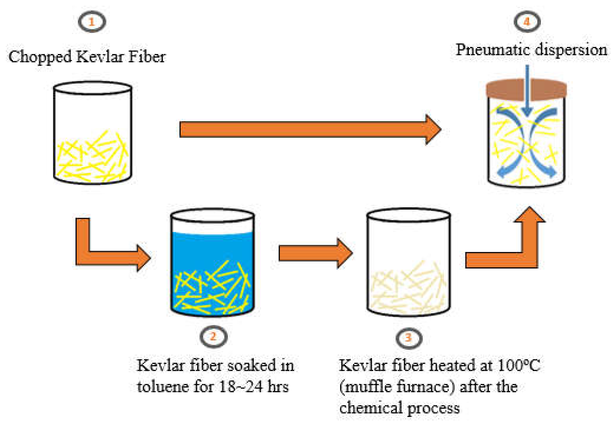
Figure 2.
Illustration and configurations of KFRC slab and momentum traps: (a) KFRC slab; (b) KFRC slab with KFRP; (c) the rebar reinforcement configuration in slab; (d) KFRC slab with momentum traps under C-4 dynamite.
Figure 2.
Illustration and configurations of KFRC slab and momentum traps: (a) KFRC slab; (b) KFRC slab with KFRP; (c) the rebar reinforcement configuration in slab; (d) KFRC slab with momentum traps under C-4 dynamite.
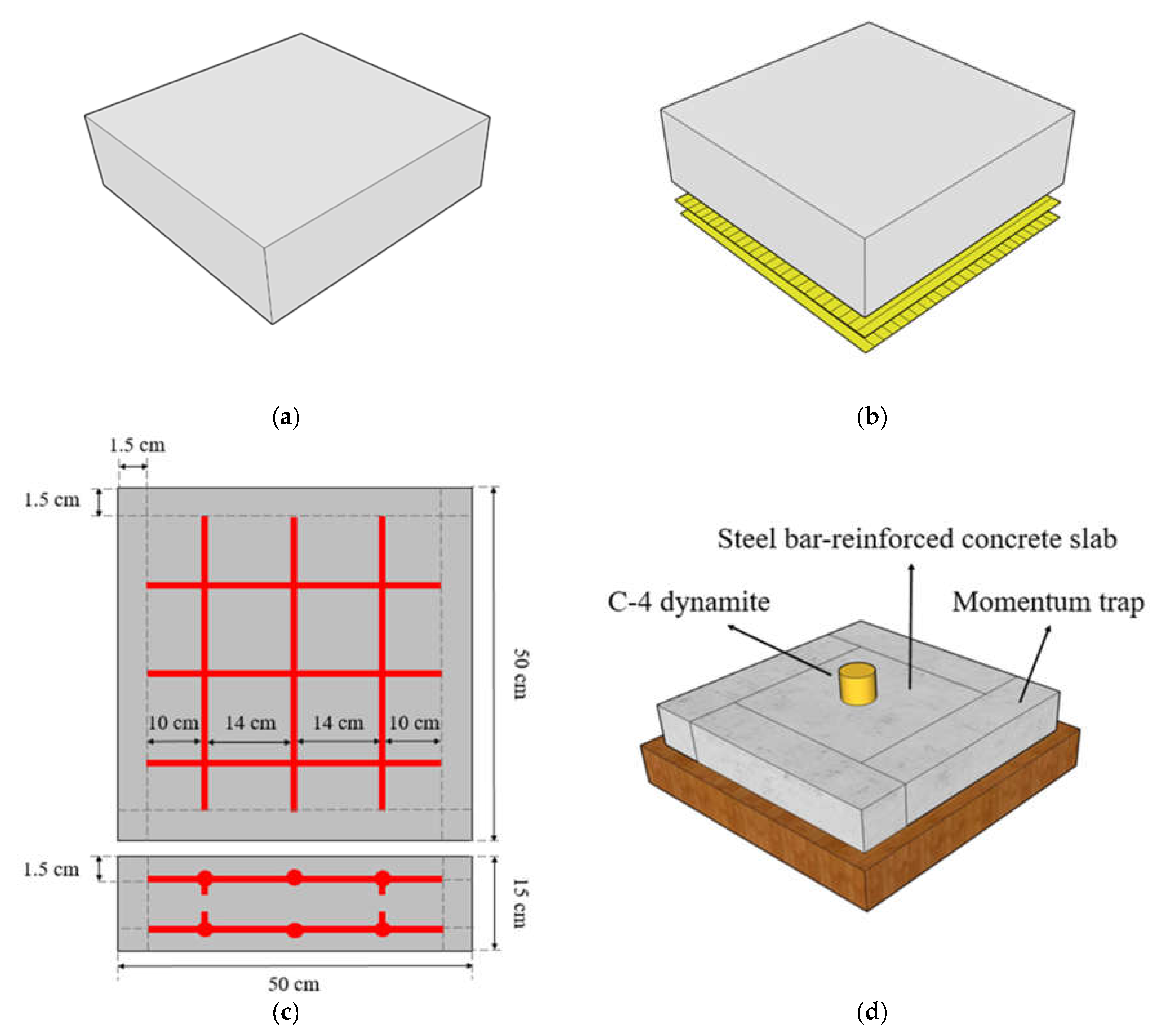
Figure 3.
NMR spectra of KF sizing.
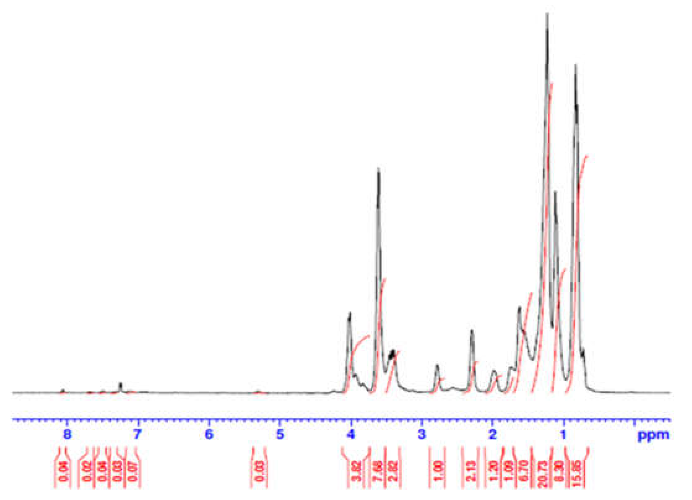
Figure 4.
Compressive strengths of the benchmark concrete and the KFRC specimens under various weight percentages.
Figure 4.
Compressive strengths of the benchmark concrete and the KFRC specimens under various weight percentages.
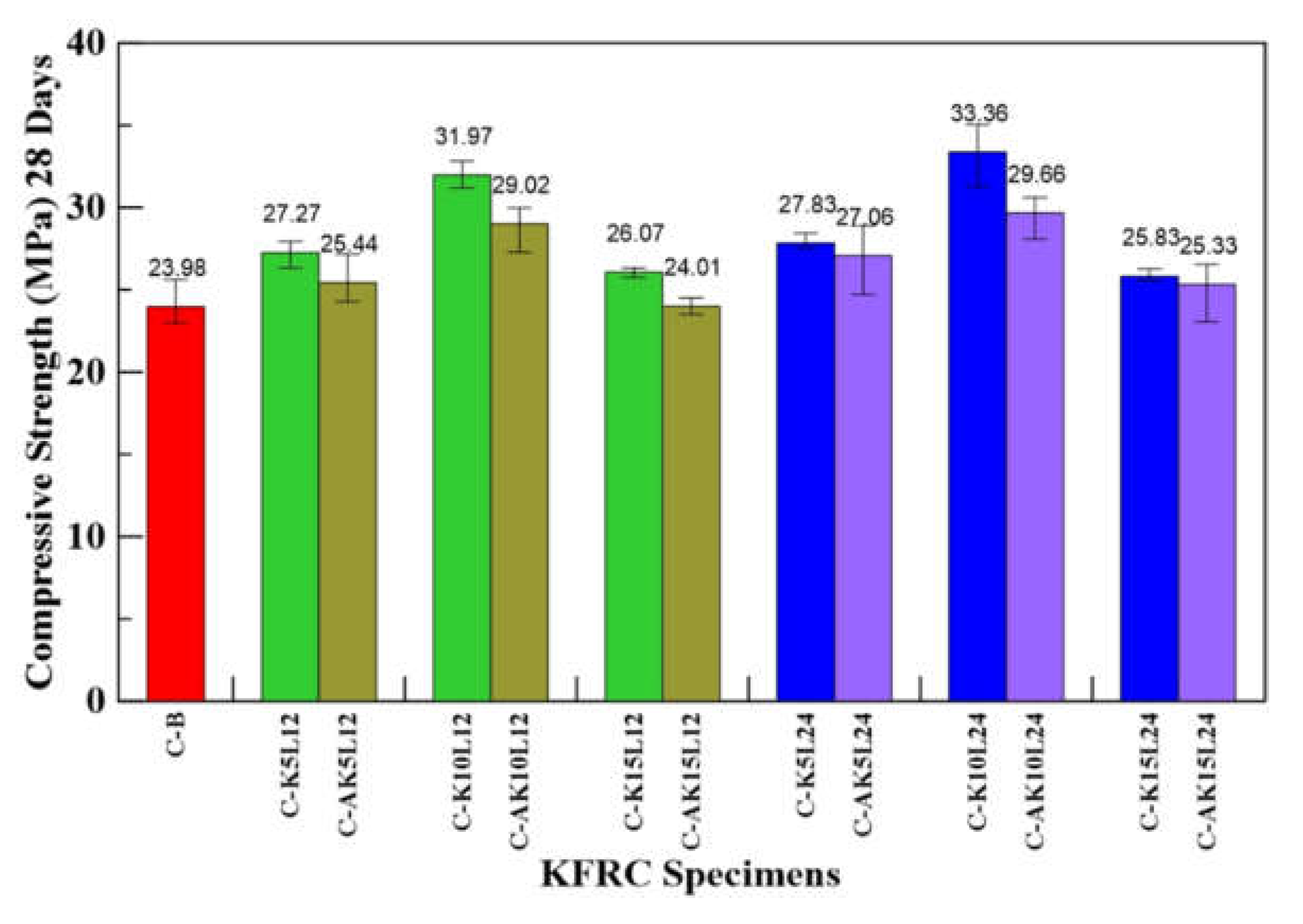
Figure 5.
Illustrations of fiber distribution into the concrete specimens: (a) low fiber content; (b) optimal fiber content; (c) high fiber content.
Figure 5.
Illustrations of fiber distribution into the concrete specimens: (a) low fiber content; (b) optimal fiber content; (c) high fiber content.
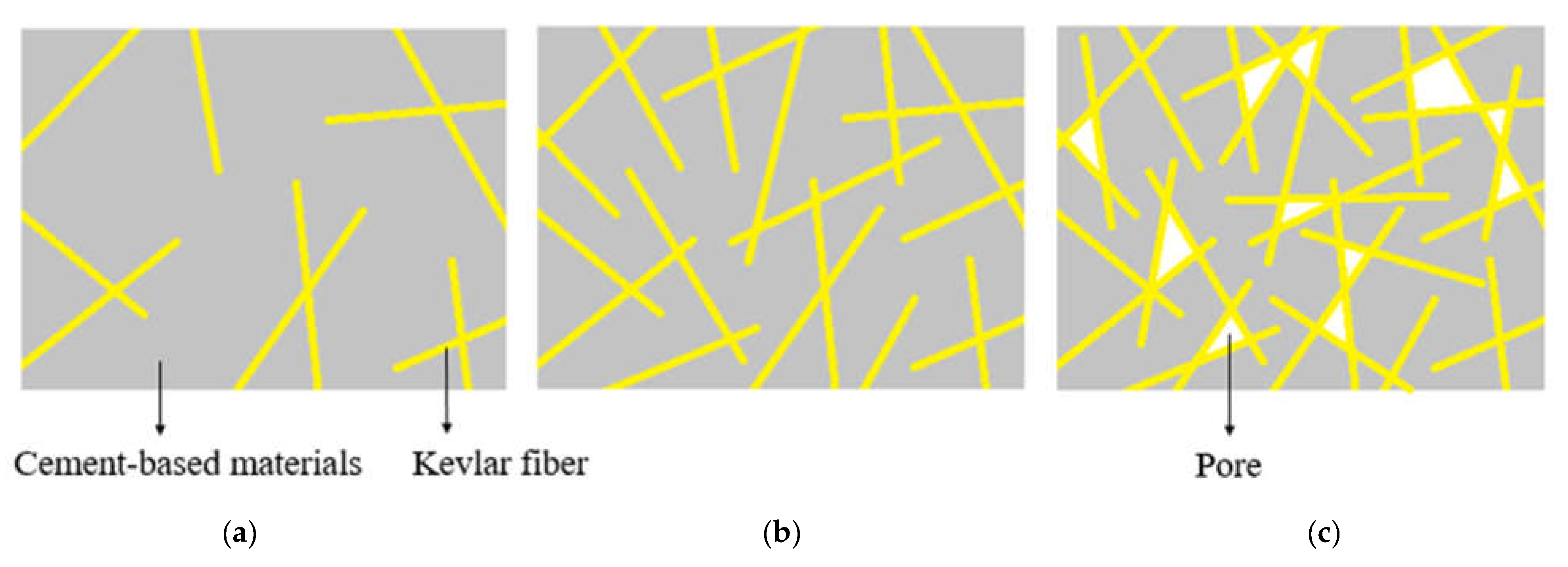
Figure 6.
Compressive strengths of the benchmark and mix-proportion KFRC specimens.

Figure 7.
Flexural strengths of the benchmark and KFRC specimens under various weight percentages.
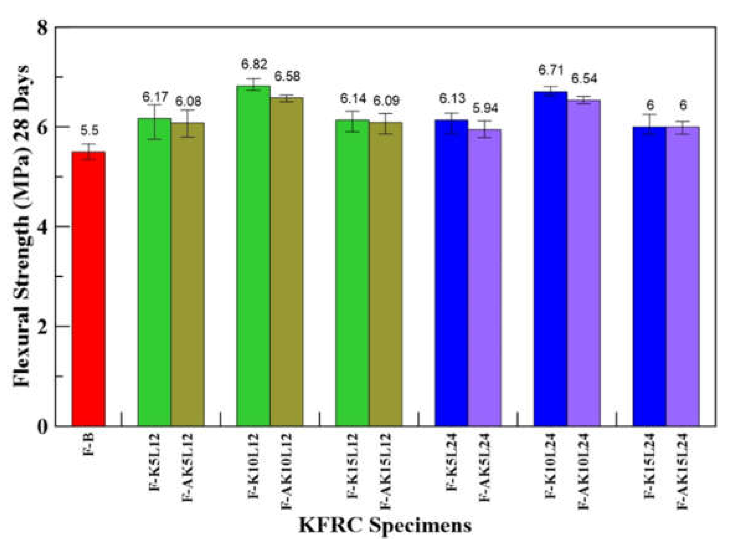
Figure 8.
Flexural strengths of the benchmark and mix-proportion KFRC specimens.
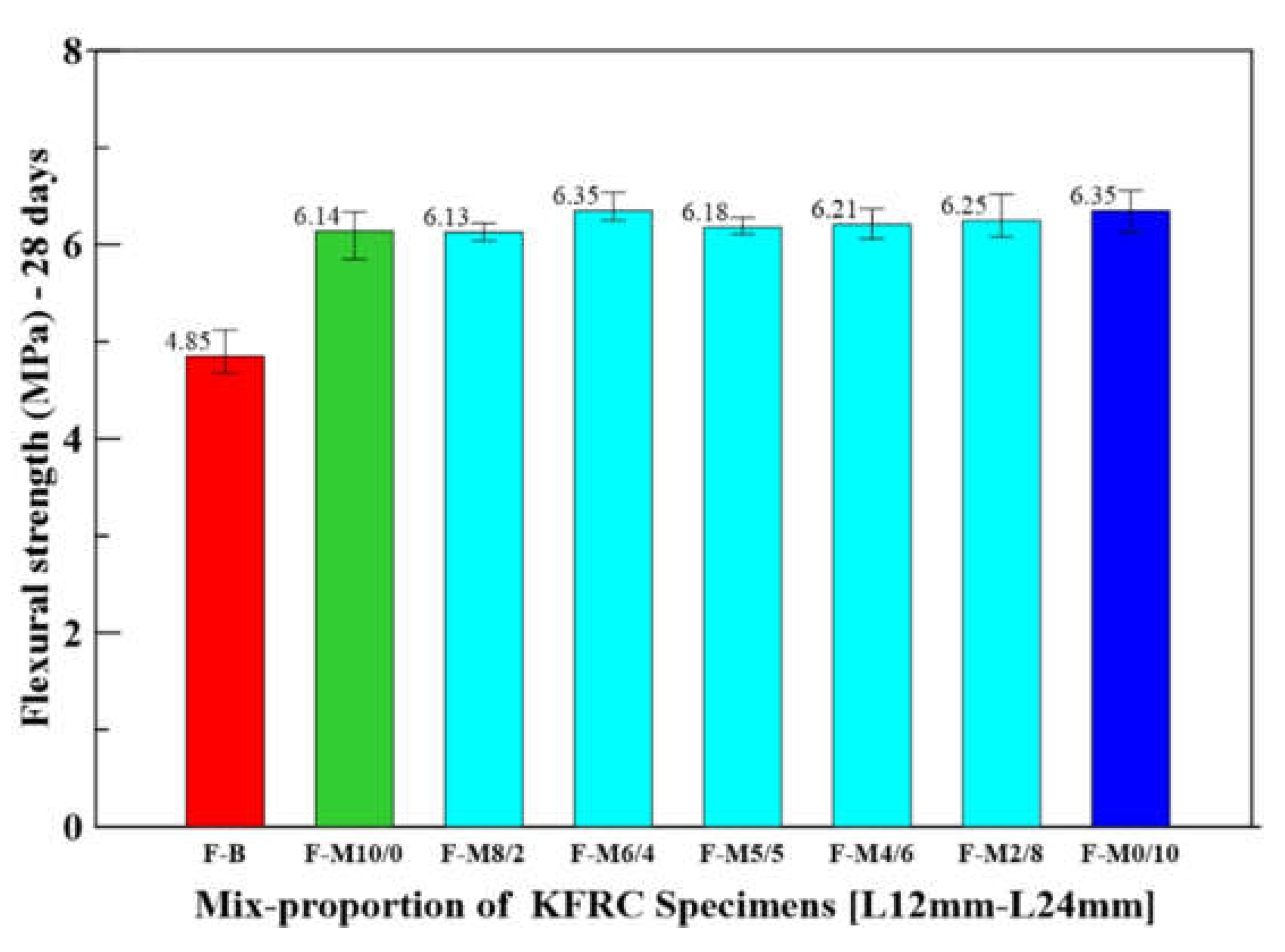
Figure 9.
Impact energy−number relationships of the benchmark and KFRC specimens.
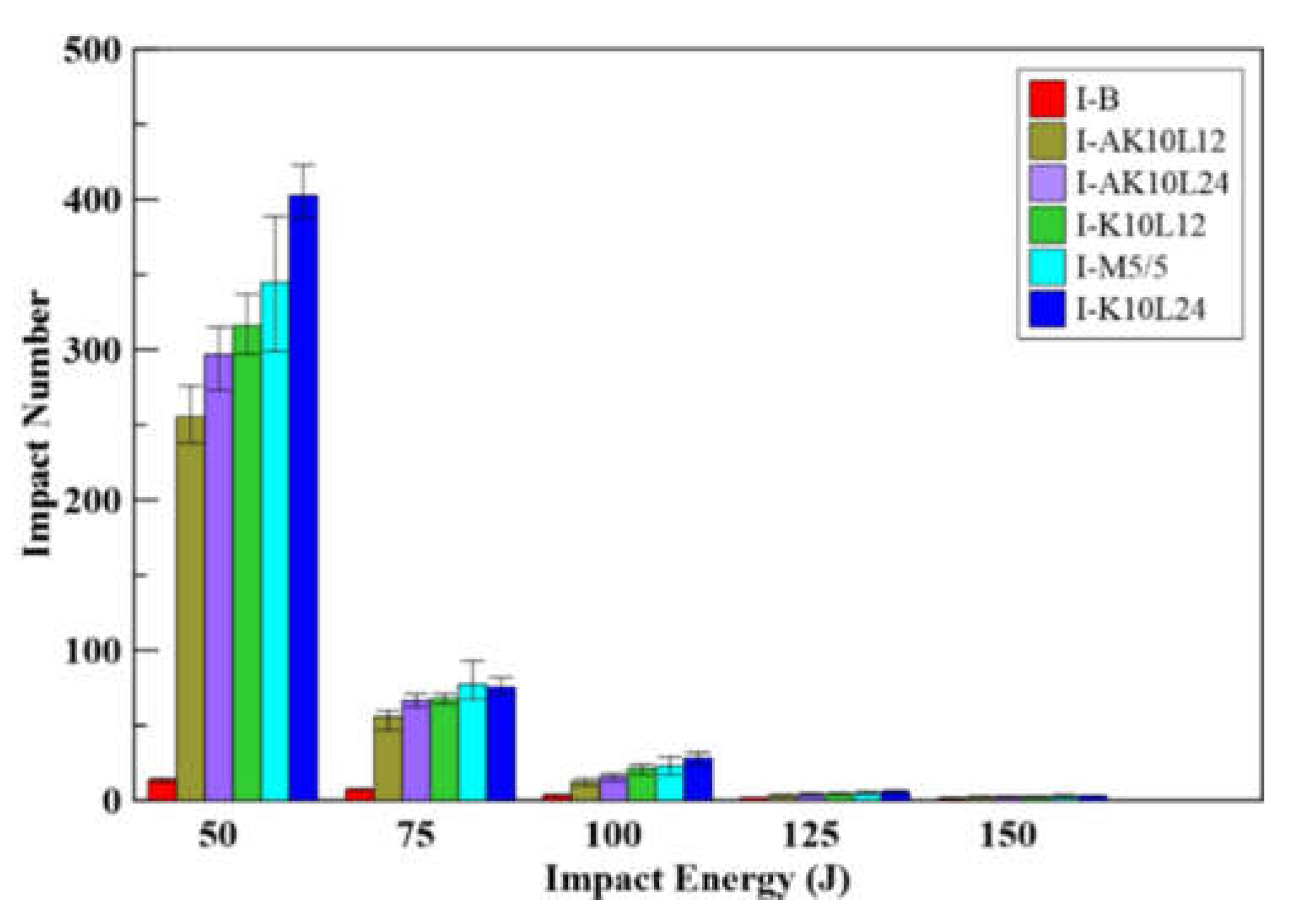
Figure 10.
The failure photos of the KFRC specimens under repeated impact at 50 J: (a) I-B; (b) I-AK10L24; (c) I-M5/5; (d) I-K10L24.
Figure 10.
The failure photos of the KFRC specimens under repeated impact at 50 J: (a) I-B; (b) I-AK10L24; (c) I-M5/5; (d) I-K10L24.

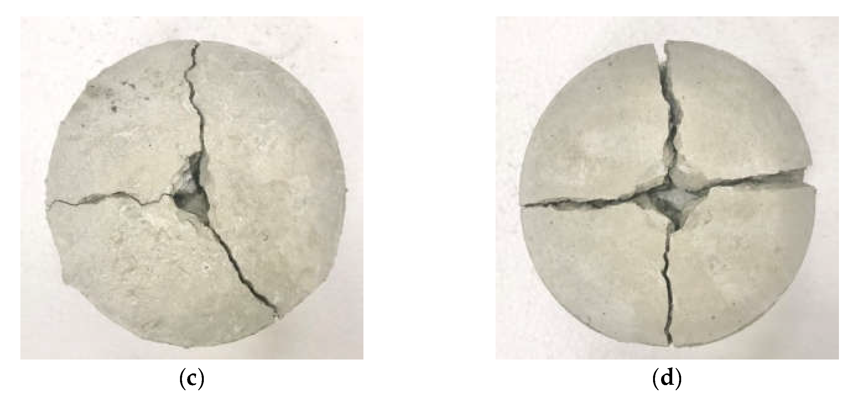
Figure 11.
Impact failure images of the I-M5/5 mix-proportion KFRC specimen by using a digital optical microscope.
Figure 11.
Impact failure images of the I-M5/5 mix-proportion KFRC specimen by using a digital optical microscope.
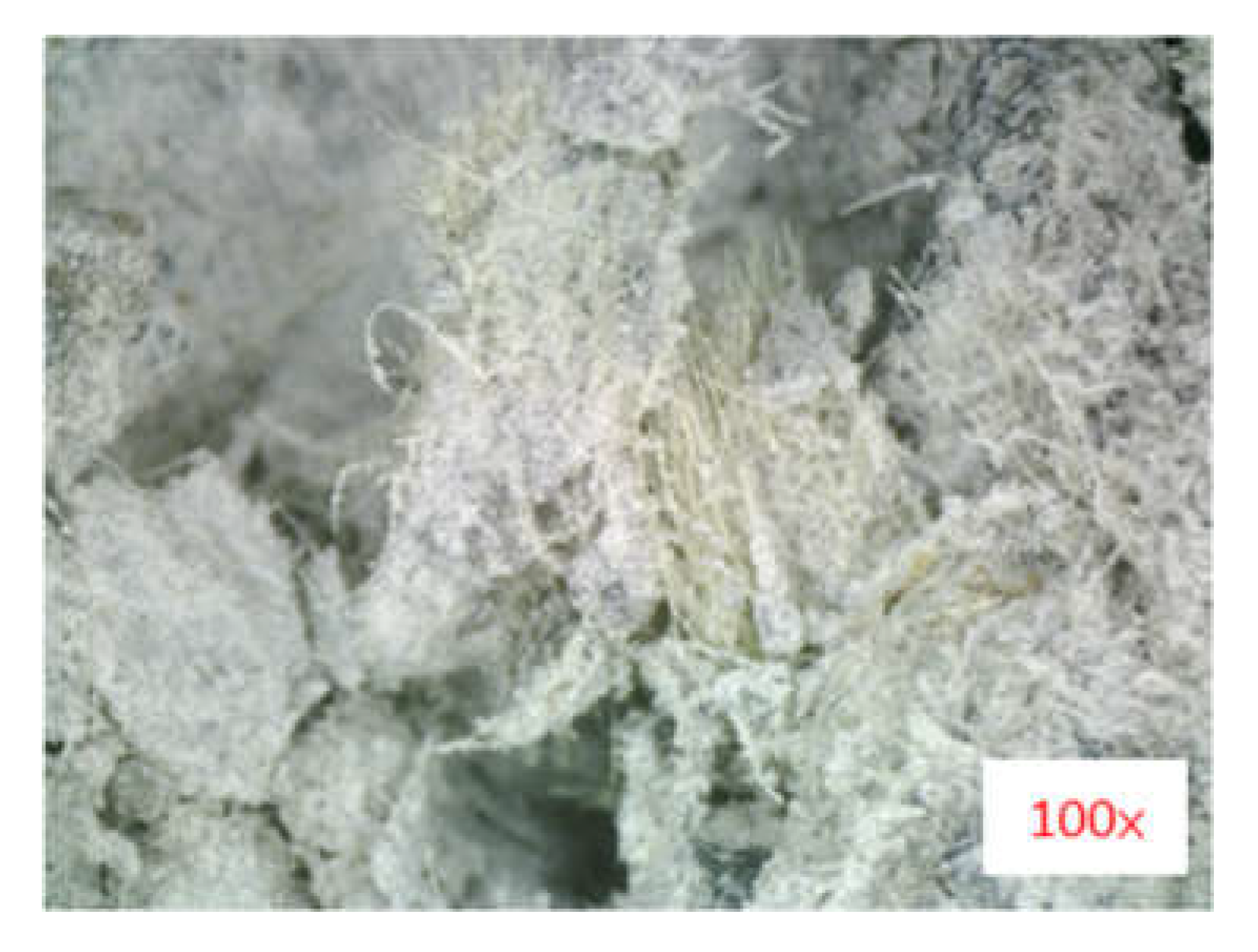
Figure 12.
The failure images of SW-B, SW-K10L24, and SW-K10L24-A specimens under shock wave loading: (a) front face of SW-B; (b) rear face of SW-B; (c) front face of SW-K10L24; (d) rear face of SW-K10L24; (e) front face of SW-K10L24-A; (f) rear face of SW-K10L24-A (with KFRP sheet); (g) rear face of SW-K10L24-A (KFRP sheet was removed).


Table 1.
Material properties of various fibers.
| Fiber | Carbon Fiber | Aramid Fiber | E-Glass Fiber | Steel Fiber | Polypropylene Fiber |
|---|---|---|---|---|---|
| Property | |||||
| Density (g/cm3) | 1.73−1.91 | 1.39−1.45 | 2.48−2.76 | 7.5−8.0 | 0.9–0.91 |
| Tensile strength (MPa) | 3300−6000 | 2700−3600 | 1500−3000 | <2600 | 140−700 |
| Elastic modulus (GPa) | 230−550 | 60−145 | 70−80 | 140−200 | 3−9 |
| Elongation (%) | 0.7−2.1 | 2.3−4.5 | 1.8−3.0 | <15 | 15 |
Table 2.
Material properties of Kevlar® 29 fiber.
| Material Property | Value |
|---|---|
| Density (g/cm3) | 1.44 |
| Tensile strength (MPa) | 2920 |
| Specific strength (MPa·cm3/g) | 2030 |
| Elastic modulus (GPa) | 70 |
| Elongation (%) | 3.6 |
Table 3.
Fineness moduli (FM) of fine and coarse aggregates.
| Sieve | Sieve Size (mm) | Weight Retained (g) | Percent Retained (%) | Cumulative Percent Retained (%) |
|---|---|---|---|---|
| 3/2” | 37.5 | 0 | 0 | 0 |
| 3/4” | 19 | 742.6 | 22.5 | 22.5 |
| 3/8” | 9.5 | 1507.1 | 45.67 | 68.17 |
| No. 4 | 4.75 | 14.8 | 0.45 | 68.62 |
| No. 8 | 2.36 | 187.9 | 5.69 | 74.32 |
| No. 16 | 1.18 | 270.3 | 8.19 | 82.51 |
| No. 30 | 0.60 | 207.6 | 6.29 | 88.80 |
| No. 50 | 0.30 | 172.7 | 5.23 | 94.03 |
| No. 100 | 0.15 | 99.4 | 3.01 | 97.04 |
| Pan | - | 97.6 | 2.96 | - |
| Total | - | 3300.0 | 100 | 596 |
| Fineness modulus (F.M.) = 5.96 | ||||
Table 4.
The initial plan for KFRC specimens.
| Experiment | Weight Ratio(‰) | Number of KFRC Specimens | Number of Benchmarks | Total | ||||
|---|---|---|---|---|---|---|---|---|
| Original KF | Sizing-Removed KF | Mix-Proportion | ||||||
| 12 mm | 24 mm | 12 mm | 24 mm | |||||
| Compressive test | 5 | 3 | 3 | 3 | 3 | 21 | 3 | 60 |
| 10 | 3 | 3 | 3 | 3 | ||||
| 15 | 3 | 3 | 3 | 3 | ||||
| Flexural test | 5 | 3 | 3 | 3 | 3 | 21 | 3 | 60 |
| 10 | 3 | 3 | 3 | 3 | ||||
| 15 | 3 | 3 | 3 | 3 | ||||
| Impact loading test | 10 * | 20 | 20 | 20 | 20 | 20 | 20 | 120 |
| Shock wave loading test | 10 * | 2 | 1 | 3 | ||||
* Determined by flexural test results.
Table 5.
Slump values of the benchmark concrete and the KFRC specimens under various weight ratios.
| Fiber-to-Cement Weight Ratio (‰) | 0 | 5 | 10 | 15 |
| Slump (mm) | 230 | 120 | 70 | 15 |
Table 6.
Compressive strengths of the benchmark concrete and the KFRC specimens under various weight ratios of KF to cement.
Table 6.
Compressive strengths of the benchmark concrete and the KFRC specimens under various weight ratios of KF to cement.
| Specimen 1 | Compressive Strength (MPa) | Increment (%) | |||
|---|---|---|---|---|---|
| 1 | 2 | 3 | Average | ||
| C-B | 22.99 | 23.31 | 25.62 | 23.98 | - |
| C-K5L12 | 26.34 | 27.51 | 27.94 | 27.27 | 13.7 |
| C-K10L12 | 31.17 | 31.91 | 32.82 | 31.97 | 33.3 |
| C-K15L12 | 25.75 | 26.14 | 26.34 | 26.07 | 8.7 |
| C-K5L24 | 27.48 | 27.57 | 28.43 | 27.83 | 16.1 |
| C-K10L24 | 31.28 | 33.76 | 35.05 | 33.36 | 39.1 |
| C-K15L24 | 25.58 | 25.63 | 26.28 | 25.83 | 7.7 |
| C-AK5L12 | 24.27 | 24.88 | 27.17 | 25.44 | 6.1 |
| C-AK10L12 | 27.28 | 29.78 | 29.99 | 29.02 | 21.0 |
| C-AK15L12 | 23.52 | 23.99 | 24.52 | 24.01 | 0.1 |
| C-AK5L24 | 24.7 | 27.6 | 28.89 | 27.06 | 12.8 |
| C-AK10L24 | 28.08 | 30.3 | 30.6 | 29.66 | 23.7 |
| C-AK15L24 | 23.06 | 26.4 | 26.54 | 25.33 | 5.6 |
1 C, compressive strength; B, benchmark; K5, 5‰ weight ratio of original KF to cement; AK10, 10‰ weight ratio of sizing-removed KF to cement; L12, 12 mm fiber; L24, 24 mm fiber; the number 5 in the specimen names represents a 5‰ weight ratio, the number 10 in the specimen names represents a 10‰ weight ratio, and the number 15 in the specimen names represents a 15‰ weight ratio.
Table 7.
Compressive strengths of the benchmark concrete and the mix-proportion KFRC specimens.
| Specimen 1 | Benchmark | Mix-Proportion KFRC (L12 mm/L24 mm) | ||||||
|---|---|---|---|---|---|---|---|---|
| C-B | C-M10/0 | C-M8/2 | C-M6/4 | C-M5/5 | C-M4/6 | C-M2/8 | C-M0/10 | |
| Compressive strength (MPa) | 22.99 | 31.40 | 29.79 | 32.92 | 31.41 | 33.96 | 31.90 | 31.18 |
| 23.31 | 31.34 | 30.37 | 30.41 | 32.38 | 32.52 | 35.12 | 32.13 | |
| 25.62 | 30.93 | 29.85 | 29.23 | 32.37 | 30.42 | 33.04 | 32.88 | |
| Average compressive strength (MPa) | 23.98 | 31.22 | 30.00 | 30.85 | 32.05 | 32.30 | 33.35 | 32.06 |
| Increment (%) | - | 30 | 25 | 29 | 34 | 35 | 39 | 34 |
1 C, compressive strength; B, benchmark; M, mix-proportion KFRC with a mixing ratio of 12 mm KF to 24 mm KF; the number 10 in the specimen names represents a 100% mixing ratio; the number 8 in the specimen names represents a 80% mixing ratio; the number 6 in the specimen names represents a 60% mixing ratio; the number 5 in the specimen names represents a 50% mixing ratio; the number 4 in the specimen names represents a 40% mixing ratio; the number 2 in the specimen names represents a 20% mixing ratio; the number 0 in the specimen names represents a 0% mixing ratio.
Table 8.
Flexural strengths of the benchmark and KFRC specimens under various percentages (5 ‰, 10 ‰, and 15 ‰).
Table 8.
Flexural strengths of the benchmark and KFRC specimens under various percentages (5 ‰, 10 ‰, and 15 ‰).
| Specimen | Flexural Strength (MPa) | Avg. Flexural Strength (MPa) | Increment (%) | ||
|---|---|---|---|---|---|
| F-B 1 | 5.12 | 4.76 | 4.68 | 4.85 | - |
| F-K5L12 | 5.75 | 6.31 | 6.44 | 6.17 | 27 |
| F-K10L12 | 6.73 | 6.76 | 6.97 | 6.82 | 41 |
| F-K15L12 | 5.9 | 6.19 | 6.31 | 6.14 | 27 |
| F-K5L24 | 5.87 | 6.26 | 6.28 | 6.13 | 26 |
| F-K10L24 | 6.62 | 6.69 | 6.81 | 6.71 | 38 |
| F-K15L24 | 5.85 | 5.9 | 6.25 | 6 | 24 |
| F-AK5L12 | 5.79 | 6.11 | 6.34 | 6.08 | 25 |
| F-AK10L12 | 6.5 | 6.61 | 6.64 | 6.58 | 36 |
| F-AK15L12 | 5.85 | 6.15 | 6.27 | 6.09 | 26 |
| F-AK5L24 | 5.78 | 5.93 | 6.12 | 5.94 | 23 |
| F-AK10L24 | 6.46 | 6.53 | 6.61 | 6.54 | 35 |
| F-AK15L24 | 6.03 | 6.11 | 5.85 | 6 | 24 |
1 F, flexural strength; B, benchmark; K5, 5‰ weight ratio of original KF to cement; AK10, 10‰ weight ratio of sizing-removed KF to cement; L12, 12 mm fiber; L24, 24 mm fiber; the number 5 in the specimen names represents a 5‰ weight ratio, the number 10 in the specimen names represents a 10‰ weight ratio, and the number 15 in the specimen names represents a 15‰ weight ratio.
Table 9.
Flexural strengths of the benchmark and mix-proportion KFRC specimens.
| Specimen | Benchmark | KF Mix-Proportion (L12 mm/L24 mm) | ||||||
|---|---|---|---|---|---|---|---|---|
| F-B 1 | F-M10/0 | F-M8/2 | F-M6/4 | F-M5/5 | F-M4/6 | F-M2/8 | F-M0/10 | |
| Flexural strength (MPa) | 5.12 | 6.14 | 6.12 | 6.54 | 6.28 | 6.20 | 6.15 | 6.56 |
| 4.76 | 6.44 | 6.22 | 6.25 | 6.11 | 6.06 | 6.52 | 6.36 | |
| 4.68 | 5.95 | 6.04 | 6.26 | 6.15 | 6.37 | 6.08 | 6.13 | |
| Average flexural strength (MPa) | 4.85 | 6.24 | 6.13 | 6.35 | 6.18 | 6.21 | 6.25 | 6.35 |
| Increase percentage (%) | - | 29 | 26 | 31 | 27 | 28 | 29 | 31 |
1 F, flexural strength; B, benchmark; M, mix-proportion KFRC with a mixing ratio of 12 mm KF to 24 mm KF; the number 10 in the specimen names represents a 100% mixing ratio; the number 8 in the specimen names represents a 80% mixing ratio; the number 6 in the specimen names represents a 60% mixing ratio; the number 5 in the specimen names represents a 50% mixing ratio; the number 4 in the specimen names represents a 40% mixing ratio; the number 2 in the specimen names represents a 20% mixing ratio; the number 0 in the specimen names represents a 0% mixing ratio.
Table 10.
Impact energy−number relationships of the benchmark specimens and the KFRC specimens.
| Specimen | Impact Energy (J) | Impact-Resistant Number | Increment (%) | ||||
|---|---|---|---|---|---|---|---|
| 1 | 2 | 3 | 4 | Average | |||
| I-B 1 | 150 | 1 | 1 | 1 | 2 | 1.3 | - |
| 125 | 2 | 2 | 2 | 2 | 2.0 | - | |
| 100 | 3 | 4 | 4 | 4 | 3.8 | - | |
| 75 | 7 | 7 | 8 | 8 | 7.5 | - | |
| 50 | 12 | 14 | 14 | 15 | 13.8 | - | |
| I-AK10L12 1 | 150 | 2 | 2 | 2 | 3 | 2.3 | 80 |
| 125 | 3 | 3 | 4 | 4 | 3.5 | 75 | |
| 100 | 10 | 11 | 14 | 15 | 12.5 | 233 | |
| 75 | 47 | 56 | 59 | 60 | 55.5 | 640 | |
| 50 | 238 | 245 | 263 | 276 | 255.5 | 1758 | |
| I-AK10L24 1 | 150 | 2 | 2 | 3 | 3 | 2.5 | 100 |
| 125 | 3 | 4 | 4 | 5 | 4.0 | 100 | |
| 100 | 13 | 16 | 17 | 18 | 16.0 | 327 | |
| 75 | 62 | 66 | 67 | 71 | 66.5 | 787 | |
| 50 | 273 | 291 | 308 | 315 | 296.8 | 2058 | |
| I-K10L12 1 | 150 | 2 | 2 | 3 | 3 | 2.5 | 100 |
| 125 | 4 | 4 | 4 | 5 | 4.3 | 113 | |
| 100 | 17 | 21 | 22 | 24 | 21.0 | 460 | |
| 75 | 64 | 66 | 70 | 71 | 67.8 | 803 | |
| 50 | 297 | 312 | 318 | 337 | 316.0 | 2198 | |
| I-K10L24 1 | 150 | 3 | 3 | 3 | 3 | 3.0 | 140 |
| 125 | 5 | 5 | 6 | 7 | 5.8 | 188 | |
| 100 | 24 | 28 | 29 | 32 | 28.3 | 653 | |
| 75 | 71 | 72 | 77 | 82 | 75.5 | 907 | |
| 50 | 388 | 397 | 402 | 423 | 402.5 | 2827 | |
| I-M5/5 2 | 150 | 2 | 2 | 3 | 4 | 2.8 | 120 |
| 125 | 4 | 4 | 5 | 6 | 4.8 | 138 | |
| 100 | 17 | 22 | 24 | 29 | 23.0 | 513 | |
| 75 | 67 | 72 | 77 | 93 | 77.3 | 930 | |
| 50 | 299 | 334 | 356 | 389 | 344.5 | 2405 | |
1 I, impact test; B, benchmark; K10, 10‰ weight ratio of original KF to cement; AK10, 10‰ weight ratio of sizing-removed KF to cement; L12, 12 mm fiber; L24, 24 mm fiber. 2 I, impact test; M, mix-proportion KFRC with a mixing ratio of 12 mm KF to 24 mm KF; the number 5 in the specimen name I-M5/5 refers to a 50% mixing ratio.
Table 11.
Failure types and external damage measurements of the benchmark and KFRC specimens.
| Specimen 1 | Slab Surface | Depth (cm) | Min. Diameter (cm) | Max. Diameter (cm) | Damaged Area (cm2) | Failure Type |
|---|---|---|---|---|---|---|
| SW-B | Front | - | 30 | 37 | 881 | Perforation and breaching |
| Rear | - | 34 | 47 | 1288 | ||
| SW-K10L24 | Front | - | 20 | 28 | 452 | Perforation and breaching |
| Rear | - | 25 | 40 | 830 | ||
| SW-K10L24-A | Front | 3.2 | 18 | 24 | 346 | Cratering |
| Rear (removing KFRP) | 5.6 | 20 | 37 | 638 | Spalling |
1 SW, shock wave test; B, benchmark; K10, 10‰ weight ratio of original KF to cement; L24, 24 mm fiber; A, attached KFRP on the bottom of the slab.
Publisher’s Note: MDPI stays neutral with regard to jurisdictional claims in published maps and institutional affiliations. |
© 2022 by the authors. Licensee MDPI, Basel, Switzerland. This article is an open access article distributed under the terms and conditions of the Creative Commons Attribution (CC BY) license (https://creativecommons.org/licenses/by/4.0/).
Share and Cite
MDPI and ACS Style
Li, Y.-F.; Wang, H.-F.; Syu, J.-Y.; Ramanathan, G.K.; Tsai, Y.-K. Investigating the Mechanical Performance on Static and Shock Wave Loading of Aramid Fiber-Reinforced Concrete. Fibers 2022, 10, 82. https://doi.org/10.3390/fib10100082
AMA Style
Li Y-F, Wang H-F, Syu J-Y, Ramanathan GK, Tsai Y-K. Investigating the Mechanical Performance on Static and Shock Wave Loading of Aramid Fiber-Reinforced Concrete. Fibers. 2022; 10(10):82. https://doi.org/10.3390/fib10100082
Chicago/Turabian StyleLi, Yeou-Fong, Hsin-Fu Wang, Jin-Yuan Syu, Gobinathan Kadagathur Ramanathan, and Ying-Kuan Tsai. 2022. "Investigating the Mechanical Performance on Static and Shock Wave Loading of Aramid Fiber-Reinforced Concrete" Fibers 10, no. 10: 82. https://doi.org/10.3390/fib10100082
Note that from the first issue of 2016, this journal uses article numbers instead of page numbers. See further details here.