Article

Mechanical Properties and Oxidation Behavior of Cr–Si–N Coatings

1
Department of Materials Engineering, Ming Chi University of Technology, New Taipei 24301, Taiwan
2
Center for Plasma and Thin Film Technologies, Ming Chi University of Technology, New Taipei 24301, Taiwan
3
Institute of Materials Engineering, National Taiwan Ocean University, Keelung 20224, Taiwan
4
Center of Excellence for Ocean Engineering, National Taiwan Ocean University, Keelung 20224, Taiwan
*
Author to whom correspondence should be addressed.
Coatings 2019, 9(8), 528; https://doi.org/10.3390/coatings9080528
Submission received: 28 July 2019 / Revised: 16 August 2019 / Accepted: 19 August 2019 / Published: 20 August 2019
(This article belongs to the Special Issue Physical Vapor Deposition)

Abstract

:
Cr–Si–N coatings were prepared through reactive direct current magneton sputtering using a high N2/Ar flow ratio of 1. The addition of Si to improve the mechanical properties and oxidation resistance of Cr–N coatings was examined. The results indicated that the Cr–Si–N coatings with an Si content of <12 at % and an N content of >50 at % exhibited a cubic CrN phase with a columnar structure, whereas the coatings with 14 at % Si comprised of a nanocomposite structure, and the coatings with 16–18 at % Si were near-amorphous. The nanocomposite Cr32Si14N54 coating possessed hardness and Young’s modulus values of 17 and 209 GPa, respectively, accompanied with a hardness to effective Young’s modulus (H/E*) value of 0.077 and an elastic recovery (We) level of 55%—all the properties were highest within the as-deposited coating. The addition of Si was also beneficial to reduce the surface roughness and improve the oxidation resistance.

1. Introduction

Chromium nitride thin films have attracted widespread industrial applications [1] and academic studies because of their excellent mechanical properties [2,3], wear resistance [4,5], corrosion resistance [6], and oxidation resistance [7,8,9,10]. To meet the increasingly advanced industrial demands, ternary composite films have attracted researchers’ attentions. Previous studies have demonstrated improved mechanical properties and oxidation resistance of chromium nitride by adding a third element, such as CrAlN [11,12], CrSiN [13], CrWN [14,15], and CrZrN [16]. CrSiN coatings have become a popular research topic [17,18,19,20,21,22,23,24,25,26], following the development of nanocomposite coatings and the pursuit of enhancing the mechanical properties. Nanocomposite nitride coatings (recognized as nc-MenN/a-Si3N4) [21,27,28] consist of transition-metal nitride nanocrystallities surrounded by amorphous tissue. The main hardening mechanisms of Me–Si–N coatings were solid-solution strengthening and nanocomposite formation hardening [21,23], whereas the residual stress effect was next in importance [21]. Stoichiometric CrN coatings exhibited their lowest oxidation rate, up to 800 °C, caused by the lowest Cr2O3 growth rate on the surface [7], whereas stoichiometric CrNx coatings included Cr and Cr2N phases, promoting their oxidation rates. However, crystalline Cr2O3 oxides roughened the surface to a high level of 55.5–200 nm [7,29]. The increased oxidation resistance of Cr–Si–N coatings at 800 °C was attributed to the deficiency of grain boundaries in the original amorphous Si3N4 phase within the coatings and the formation of amorphous SiO2, together with crystalline Cr2O3 on the coating surface [24,30]. The decomposition of CrN into Cr2N and N2 above 900 °C and subsequent oxidation restricted the oxidation resistance of Cr–Si–N coatings, and only the coatings with certain Si contents exhibited excellent oxidation resistance up to 1000 °C [30]. Previous studies [2,31] reported that increasing the nitrogen gas flow rate supported the addition of N into the Cr matrix and produced various phases from Cr + Cr2N to Cr2N, Cr2N + CrN, and CrN. In this study, Cr–Si–N coatings were prepared through magneton cosputtering using a high N2/Ar flow ratio of 1 to confirm the formation of the CrN phase. The goals of this work focused on the feasibility of introducing Si into Cr–N coatings to improve the mechanical properties and oxidation resistance. The oxidation resistance was evaluated at 600 °C in a 15 ppm O2–N2 atmosphere for 8 h and 16 h; this atmosphere and temperature provided realistic conditions for molding optical glass elements [32]. Also examined were the effects of Si addition on the structural variation, surface roughness, and residual stress of the annealed Cr–Si–N coatings.

2. Materials and Methods

Cr–Si–N coatings were prepared on silicon substrates and polished SUS420 stainless steel substrates through reactive direct current magneton cosputtering. The samples prepared on the two kinds of substrate were fabricated in one batch. The sputtering equipment and processes were similar to those used for fabricating Hf–Si–N/Ti/Si assemblies, which were described in detail in a previous study [33]. Targets of 99.95% pure Cr and 99.999% Si with a diameter of 50.8 mm were adopted as source materials. The target to substrate distance was kept at 90 mm. The substrate holder was electrically grounded and rotated at a speed of 5 rpm without heating. Both the flow rates of Ar (99.99%) and N2 (99.999%) were maintained at 10 sccm to maintain the working pressure at 0.4 Pa. Cr interlayers were deposited on the substrates to improve adhesion between the coatings and the substrates. Cr–Si–N coatings were deposited by applying a power of 100 W on the Cr target, whereas the Si target powers were set at 0, 25, 50, 75, 100, 125, and 150 W. A field emission electron probe microanalyzer (FE-EPMA, JXA-8500F, JEOL, Akishima, Japan) equipped with wavelength dispersive spectrometers was adopted to determine the chemical compositions of the coatings. The phases of the coatings were identified using a conventional X-ray diffractometer (XRD, X’Pert PRO MPD, PANalytical, Almelo, The Netherlands) with Cu Kα radiation. The thickness of coatings was evaluated by field-emission scanning electron microscopy (FE-SEM, S4800, Hitachi, Tokyo, Japan). The nanostructure was examined using a transmission electron microscope (TEM, JEM-2010F, JEOL, Tokyo, Japan) equipped with energy dispersive spectroscopy (EDS, Inca x-sight, Oxford Instruments, Tokyo, Japan). The TEM samples were prepared by applying a focused ion beam system (FEI Nova 200, Hillsboro, OR, USA). A Pt layer was deposited to protect each free surface during sample preparation. The surface roughness values, Ra, of the coatings were evaluated using an atomic force microscope (AFM, Dimension 3100 SPM, NanoScope IIIa, Veeco, Santa Barbara, CA, USA). The hardness and Young’s modulus values of the coatings were measured using a nanoindentation tester (TI-900 Triboindenter, Hysitron, Minneapolis, MN, USA) and calculated based on the Oliver and Pharr method [34]. The nanoindenter was equipped with a Berkovich diamond probe tip, which was 200 nm in diameter. The Poisson’s ratio used was 0.24 for CrN [35]. The residual stress of the coatings was measured by the curvature method using Stoney’s equation [33,36]. A scratch test (Scratch Tester, J & L Tech. Co., Gyeonggi-do, Korea), up to a maximum load of 50 N, was adopted to explore the adhesion properties of films on stainless steel substrates.

3. Results and Discussion

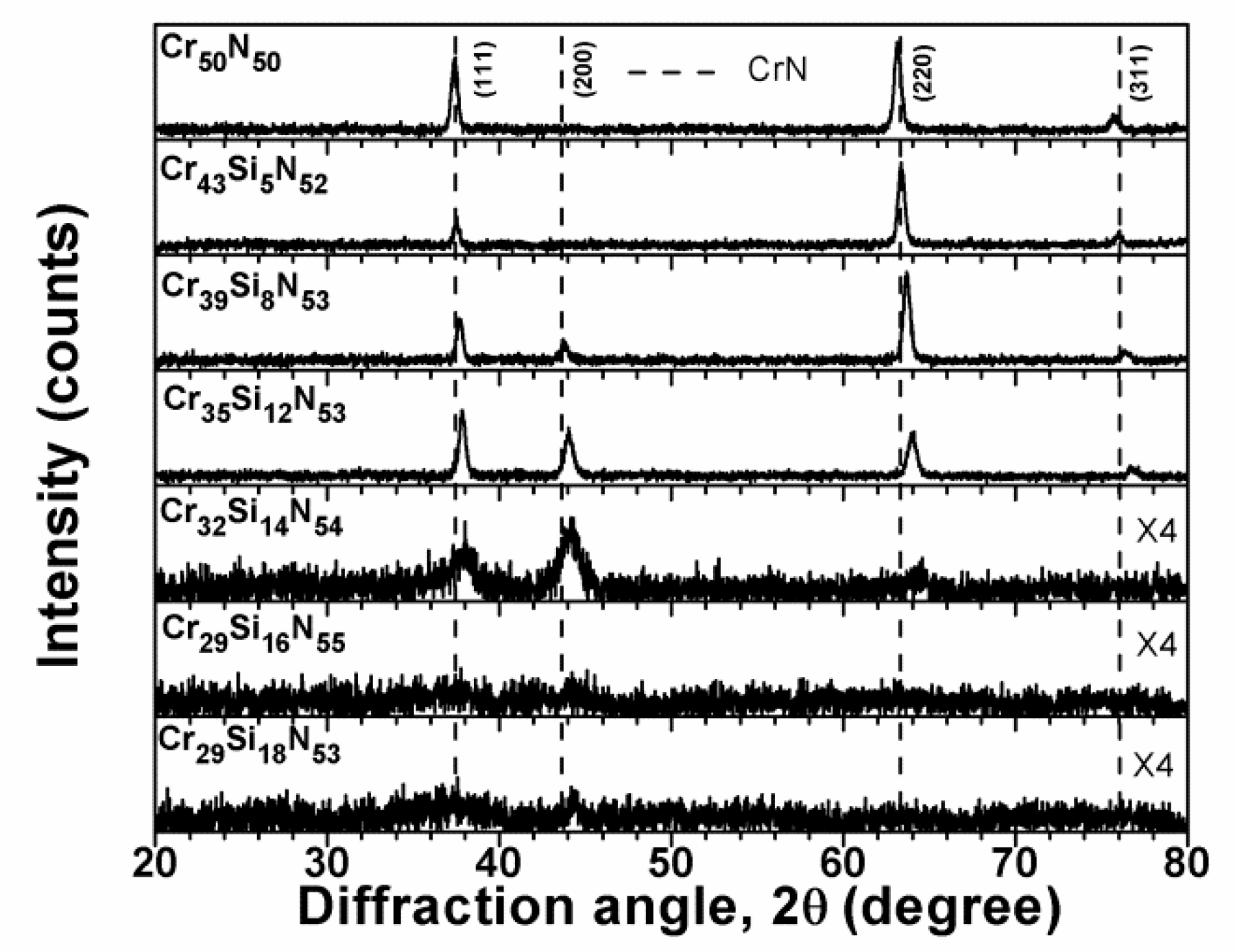
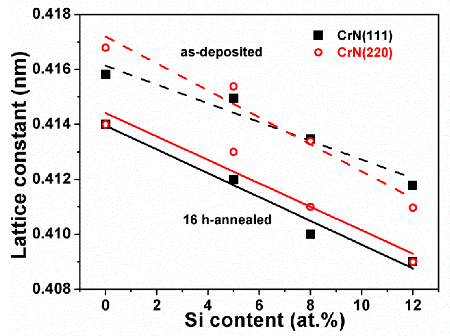
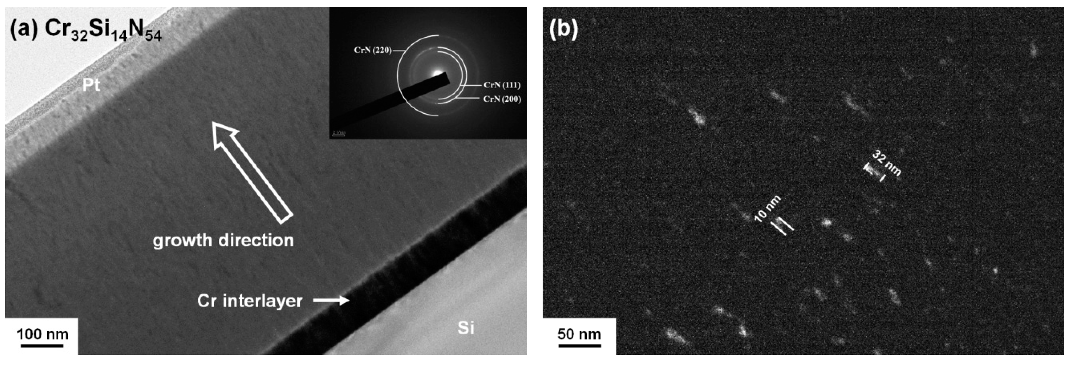
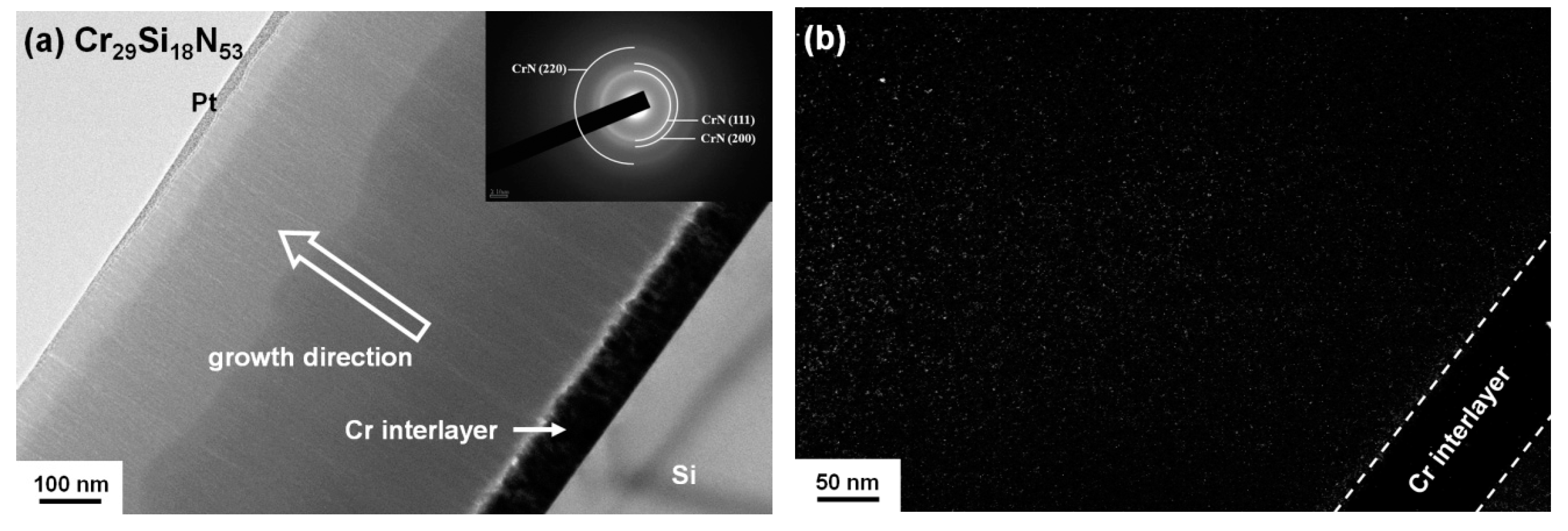
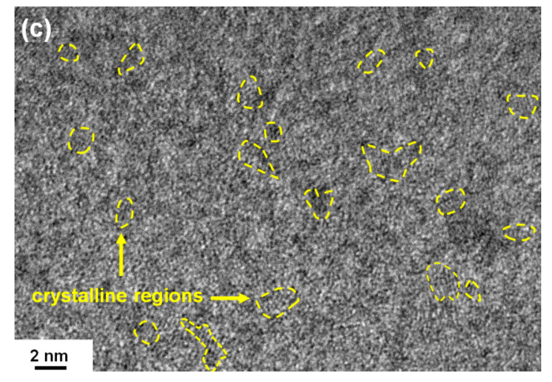
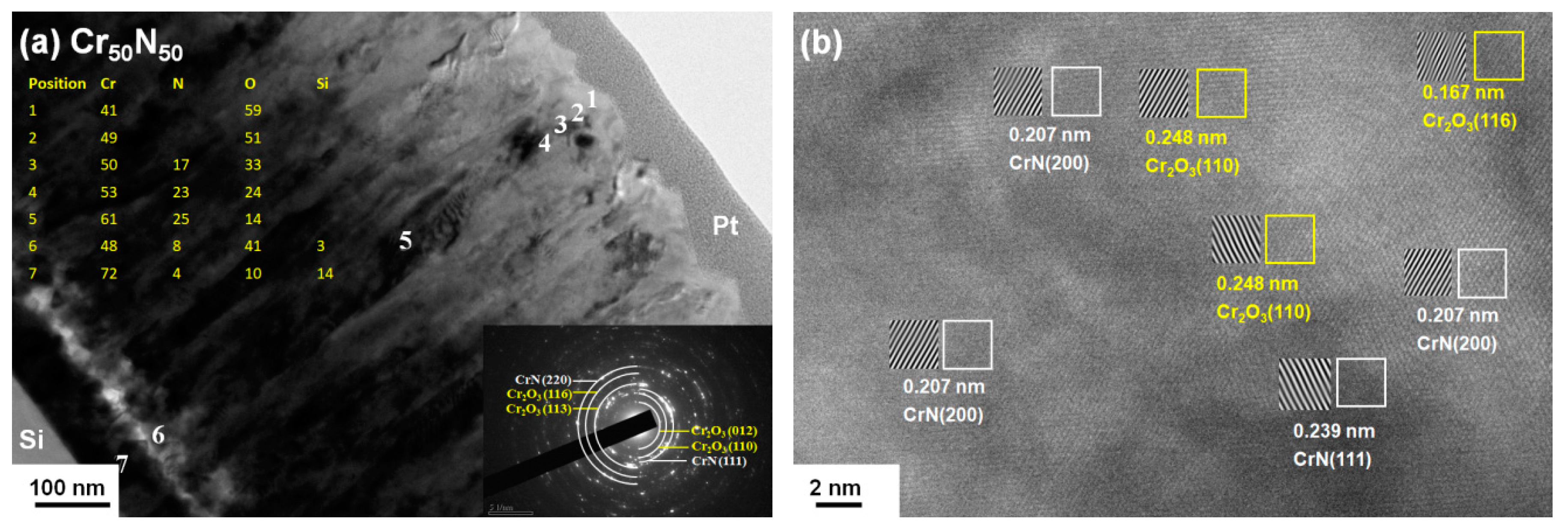
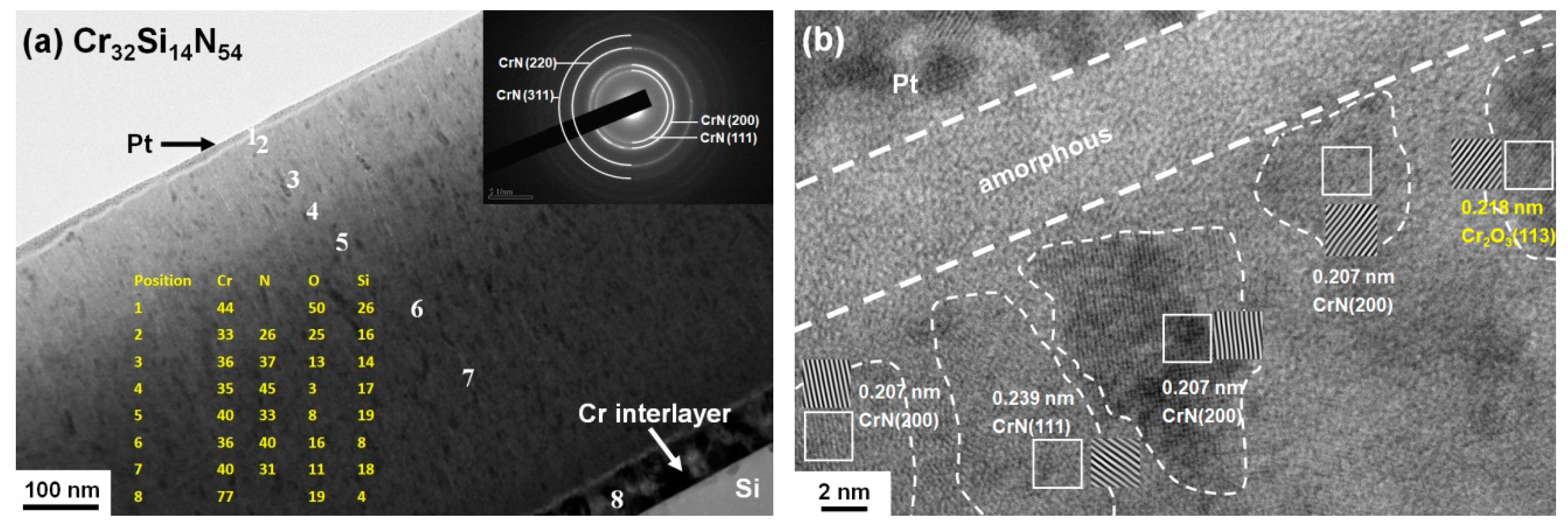
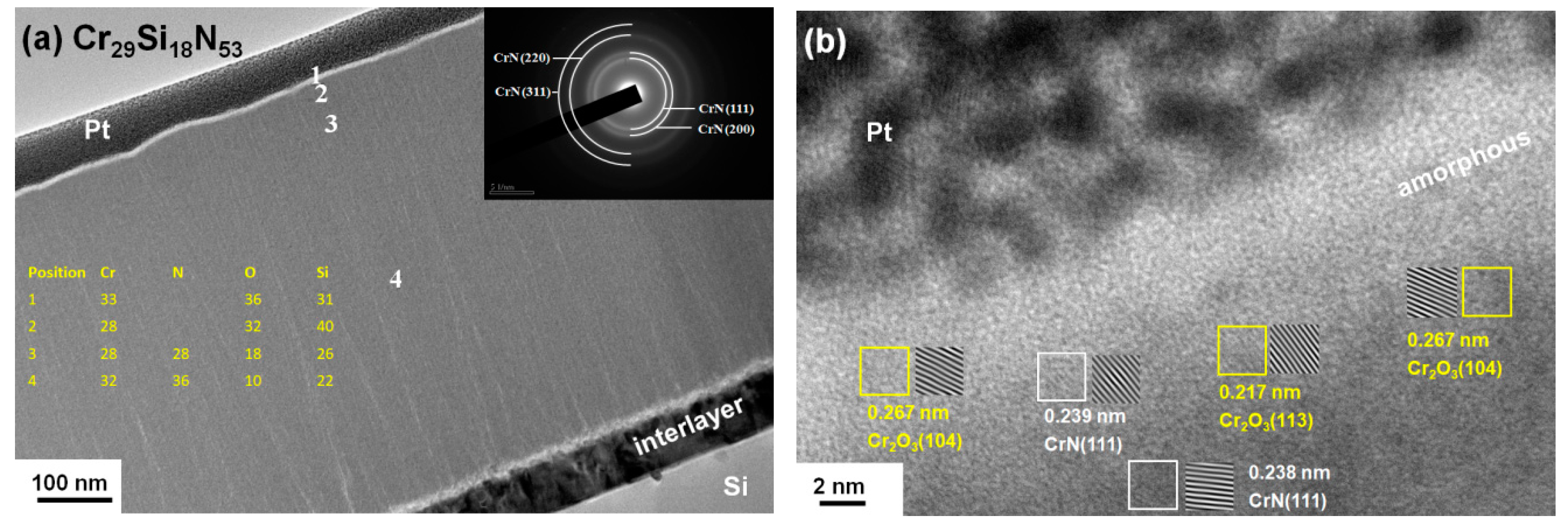
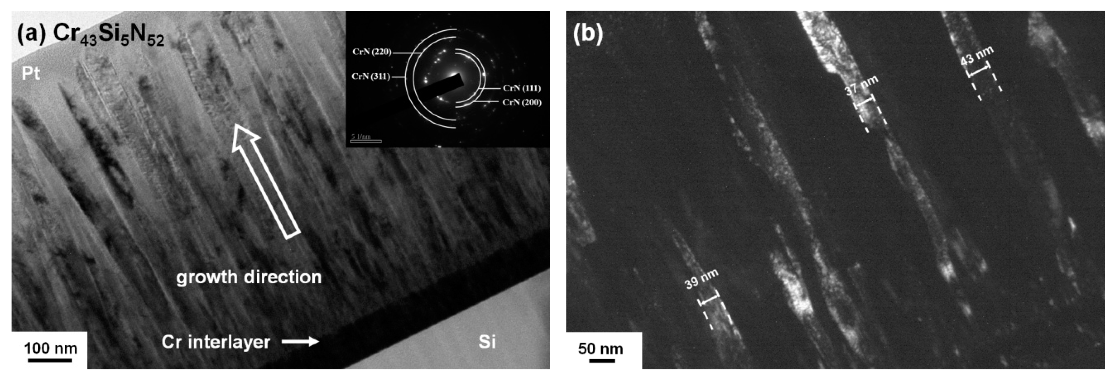
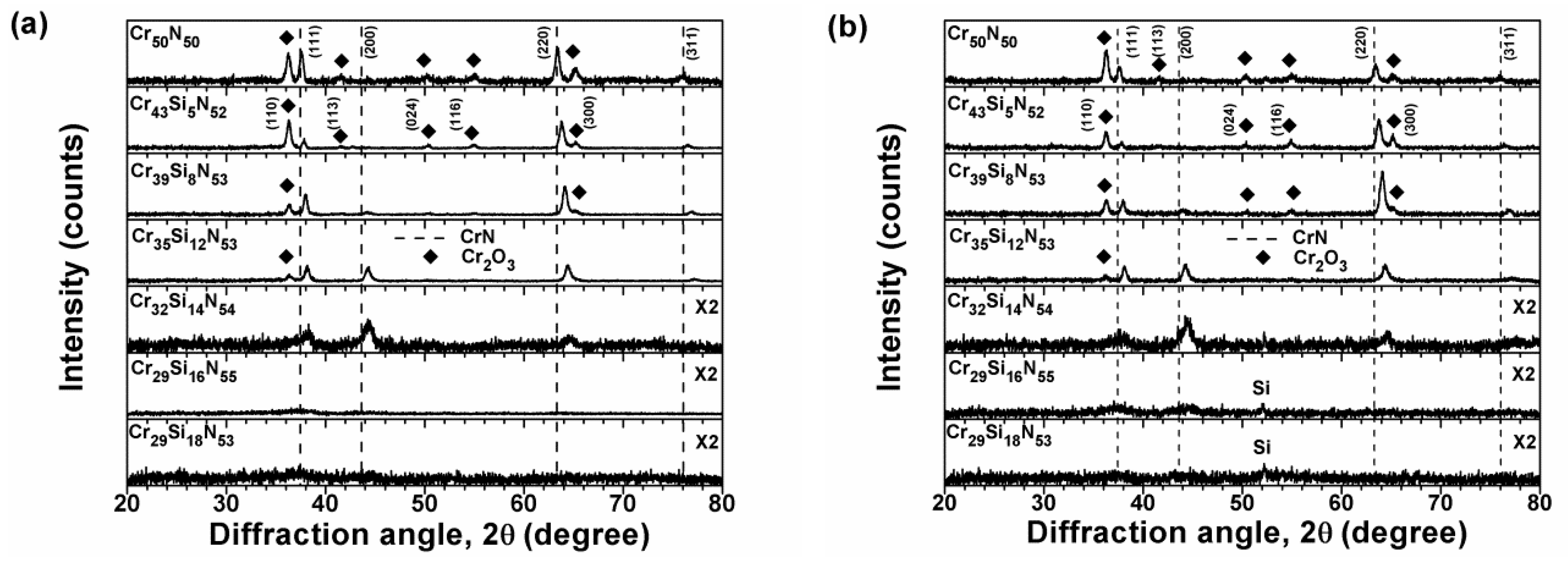
3.1. Chemical Compositions and Microstructure of As-Deposited Cr–Si–N Coatings

Table 1 shows the chemical compositions and deposition rates of the as-deposited CrN and Cr–Si–N coatings, prepared using various Si target powers. The oxygen contents in the as-deposited coatings were less than 5 at %. After ignoring the O content in these coatings, the N content was higher than 50 at % and the Si content varied from 0 to 18 at % with an increasing Si target power from 0 to 150 W, whereas the deposition rate increased from 5.9 to 9.8 nm/min, simultaneously. The thicknesses of the Cr50N50, Cr43Si5N52, Cr39Si8N53, Cr35Si12N53, Cr32Si14N54, Cr29Si16N55, and Cr29Si18N53 coatings were 739, 828, 853, 830, 769, 777, and 738 nm, respectively. An additional Cr37Si10N53 coating, prepared following the process for Cr39Si8N53 coatings on Ti interlayers, exhibited a chemical composition of 35.2 at % Cr, 9.4 at % Si, 50.4 at % N, 3.2 at % O, 1.8 at % Ti, and a thickness of 839 nm, which implied that the aforementioned chemical composition analysis for the as-deposited CrN and Cr–Si–N coatings affected by the Cr interlayer was limited.
Figure 1 shows the XRD patterns of the as-deposited Cr–Si–N coatings. Because both the flow rates of Ar and N2 were maintained at 10 sccm, forming a high flow ratio of the reactive gas to total gas, the deposited coatings with an Si content less than 12 at % exhibited a crystalline cubic phase of CrN without Cr or Cr2N. The intensities and widths of the reflections of the Cr32Si14N54 coatings were, respectively, lower and broader than those of the crystalline coatings, implying that the Cr32Si14N54 coatings formed a nanocomposite structure, whereas further increasing the Si content to 16–18 at % resulted in a near-amorphous phase, also named an X-ray amorphous phase. The diffraction reflections of the crystalline Cr–Si–N coatings shifted toward higher two-theta angles with increasing Si content, which implied that the decrease in lattice constants was caused by substituting Si into the CrN lattice.
Figure 2 shows the lattice constants of the crystalline Cr–Si–N coatings determined using (111) and (220) reflections. The as-deposited Cr50N50 coatings exhibited lattice constants of 0.4158 and 0.4168 nm for (111) and (200) planes, respectively, which shrunk to 0.4140 nm after annealing at 600 °C in a 15 ppm O2–N2 atmosphere for 16 h; the value of 0.4140 nm was identical to the standard value of a cubic CrN phase [ICDD 00-011-0065]. The expanded lattice of the as-deposited Cr50N50 coatings indicated the existence of interstitial Cr and N atoms. By contrast, the lattice constants of the CrN phase decreased with increasing Si content in the crystalline Cr–Si–N coatings, which implied that Si atoms (radius: 110 pm) substituted the Cr atoms (128 pm) in the CrN lattice structure [26]. Sandu et al. [21] proposed a model regarding the film formation of sputtered M–Si–N coatings. The solubility limit of Si atoms in M–Si–N compounds was determined by examining the evolutions of crystalline grain sizes and lattice parameters as a function of Si addition. Si atoms segregated at the crystallite surfaces as the Si content exceeded the solubility limit, which resulted in the formation of a nanocomposite structure [21]. Benkahoul et al. [23], Martinez et al. [13], Lee and Chang [22], and Lin et al. [26] reported the solubility limit of Si atoms in Cr–Si–N coatings to be 2.3, 3, 4.1, and 4.8 at %, respectively. By contrast, the lattice constants decreased with increasing Si content up to 12 at % in this study, which suggested a high Si solubility. Park et al. [17] reported that the d-spacing of CrN (200) planes decreased with increasing Si content to 11.0 at %.
Figure 3, Figure 4 and Figure 5 display the cross-sectional TEM images and selected-area diffraction patterns (SADPs) of the Cr43Si5N52, Cr32Si14N54, and Cr29Si18N53 coatings, respectively. The Cr43Si5N52 coating—a low Si content Cr–Si–N coating—exhibited an evident columnar structure growing through the entire coating (Figure 3a), with a width of 37–43 nm examined from the dark filed image correlated with the diffraction spot of CrN (200) (Figure 3b). The Cr32Si14N54 coating, a medium-Si-content coating, comprised of a dense structure with a ringed SADP (Figure 4a). Figure 4b shows that the Cr32Si14N54 coating consisted of nanoscale crystals with a width of 10 nm and a length of 32 nm, implying the formation of a nanocomposite structure. The Cr29Si18N53 coating, a high-Si-content coating, exhibited diffused ring patterns (Figure 5a), for which the dark field image displayed lots of randomly distributed spots (Figure 5b). Moreover, the high-resolution image exhibited short-range crystalline domains with a diameter of approximately 2 nm (Figure 5c); therefore, the Cr29Si18N53 coating was near-amorphous. The structure of Cr–Si–N coatings varied from crystalline columnar, to nanocomposite, and then to a near-amorphous structure with increasing Si content. Table 1 lists the surface roughness values of the Cr–Si–N coatings. The crystalline Cr50N50 and Cr43Si5N52 coatings with low Si contents exhibited a high surface roughness of 6.2–6.8 nm, whereas the Cr39Si8N53, Cr35Si12N53, and Cr32Si14N54 coatings with medium Si contents exhibited a medium surface roughness of 2.3–2.7 nm, and the Cr29Si16N55 and Cr29Si18N53 coatings with high Si contents exhibited a low surface roughness of 0.9 nm. The surface roughness of the Cr–Si–N coatings exhibited decreased upon increasing Si content, accompanied with a decrease in crystalline dimensions.

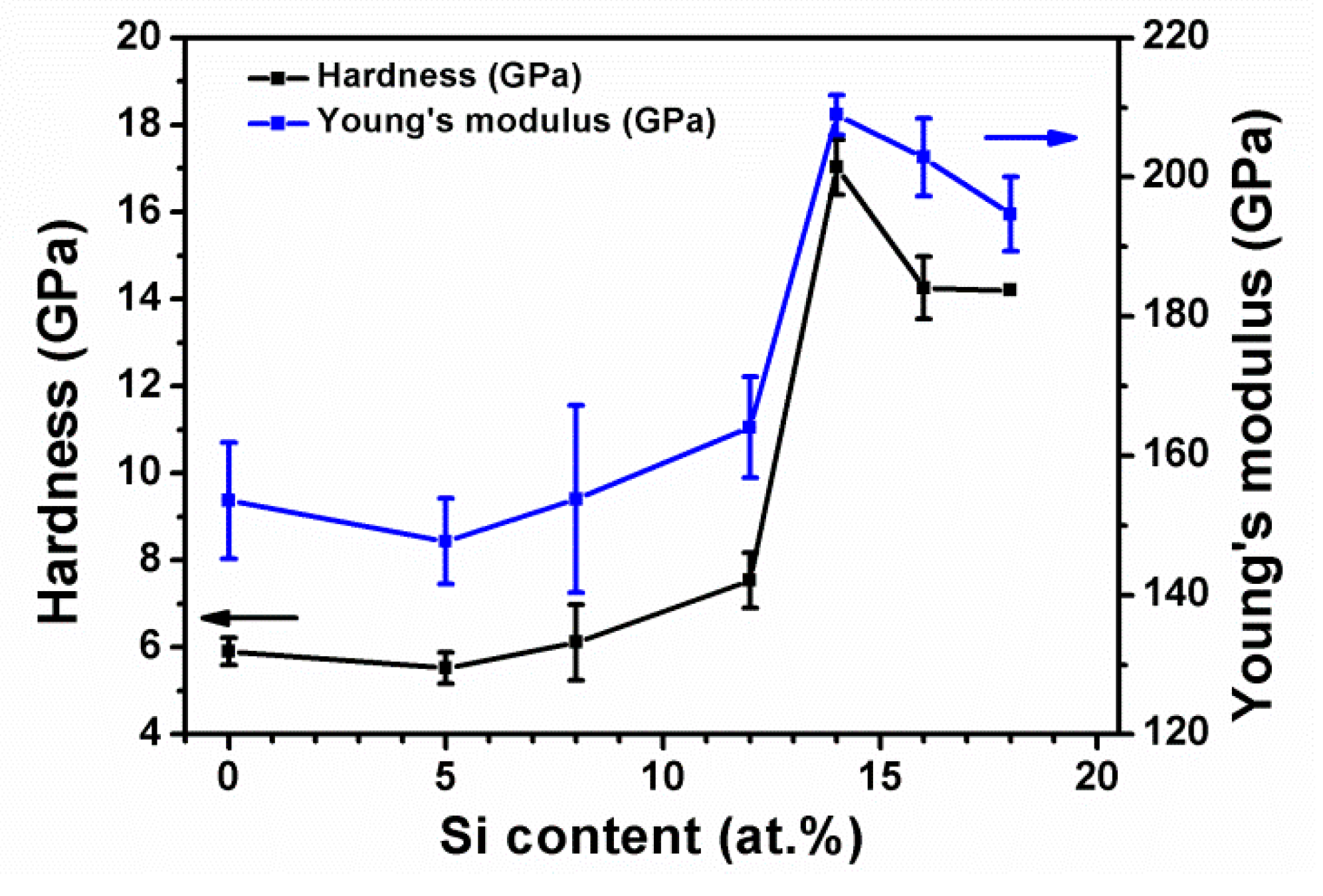
3.2. Mechanical Properties of As-Deposited Cr–Si–N Coatings

The Cr50N50 coating exhibited hardness and Young’s modulus values of 5.9 and 154 GPa (Table 2), respectively. The fact that the mechanical properties exhibited low levels should be attributed to the sputtering process having been performed without applying bias voltage and heating the substrates, which resulted in a loosely packed structure with the existence of interstitial Cr and N atoms. Previous works have reported hardness levels of 18–21 GPa for CrN coatings [2,4,11,15,19,37,38,39]. Lee et al. [37] reported a hardness of 9.6 GPa for CrN coatings prepared through pulsed direct current reactive magnetron sputtering without applying substrate bias and heated temperature; moreover, a CrN film with a hardness of 21 GPa was deposited at −290 V bias and 300 °C. Figure 6 illustrates the hardness and Young’s modulus values of Cr–Si–N coatings with various Si contents. The hardness and Young’s modulus values of the Cr–Si–N coatings initially increased with increasing Si content, reached maximum levels for the Cr32Si14N54 coating, and then decreased with the further addition of Si. The Cr32Si14N54 coating exhibited the highest hardness and Young’s modulus levels of 17 GPa and 209 GPa, respectively. Because all the as-deposited Cr–Si–N coatings exhibited a low residual stress of 0.2–0.9 GPa in tension, the hardness enhancement was attributed to the formation of solid solutions and nanocomposite structures. The decline in hardness of the coatings with a high Si content was attributed to the high volume of amorphous Si3N4. Musil [40] proposed that hard nanocomposite coatings with enhanced toughness should exceed the criteria of H/E* > 0.1 and We ≥ 60%, where E* is the effective Young’s modulus and We is the elastic recovery. The four crystalline Cr–Si–N coatings exhibited low H/E* values of 0.035–0.043 and We levels in the range of 34%–40%. The nanocomposite Cr32Si14N54 coating exhibited an H/E* value of 0.077 and a We level of 55%, which were the highest levels among the as-deposited coatings. The near-amorphous Cr29Si16N55 and Cr29Si18N53 coatings exhibited H/E* values of 0.066–0.069 and We levels of 50%–53%.
Figure 7 presents optical micrographs of the scratch tracks of Cr–Si–N coatings with various Si contents prepared on stainless steel substrates. The critical loads Lc1 and Lc2 were defined as the loads inducing the first cohesive failure and the first exposure of the substrate material, respectively [41]. The Lc1 and Lc2 values of the Cr–Si–N coatings with an Si content less than 12 at % remained at 13.1–13.9 N and 21.6–24.5 N, respectively. The Lc1 and Lc2 values decreased abruptly as the phase structure was altered from crystalline to nanocomposite. The nanocomposite and near-amorphous Cr–Si–N coatings exhibited Lc1 and Lc2 levels of 7.1–8.1 N and 15.7–16.7 N, respectively. Scratch tests indicated that the adhesion strength was related to the coatings’ phase structures.

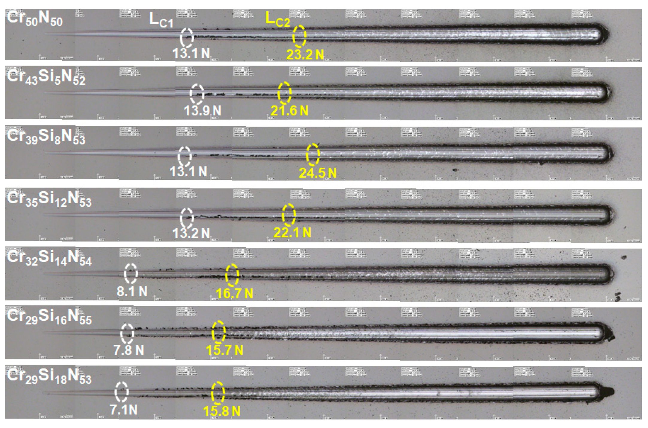
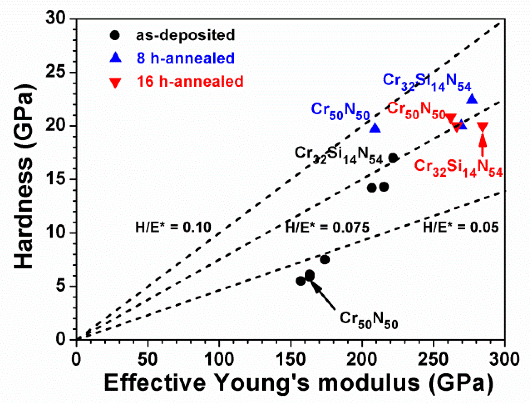
3.3. Oxidation Behavior of Cr–Si–N Coatings

Figure 8a shows the XRD patterns of the Cr–Si–N coatings annealed in 15 ppm O2–N2 at 600 °C for 8 h. Cr2O3 reflections were observed for the crystalline Cr50N50, Cr43Si5N52, Cr39Si8N53, and Cr35Si12N53 coatings, whereas the nanocomposite Cr32Si14N54 and near-amorphous Cr29Si16N55 and Cr29Si18N53 coatings maintained patterns similar to those of samples in the as-deposited state. Figure 8b shows the XRD patterns of the 16 h-annealed samples, which were similar to those of the 8 h-annealed samples. Figure 2 shows the lattice constants of the as-deposited and 16 h-annealed crystalline Cr–Si–N coatings and indicates that the lattice constants shrink after annealing. Moreover, all the crystalline Cr–Si–N coatings exhibited a similar decrease in the lattice constants after annealing, which implied that the expanded lattices formed due to sputter processes accompanied with interstitial Cr and N atoms were recovered after annealing. Furthermore, the lattice constants of the annealed coatings exhibited a decreasing tendency with increasing Si content, which implied that Si atoms still substituted the Cr atoms in the CrN lattice at 600 °C and that the nitride phase remained as CrN. Thobor-Keck et al. [18] reported that the addition of 3 at % Si into CrN coatings inhibited the formation of the Cr2N phase at 750 °C.
Figure 9a shows a cross-sectional TEM image of a 16 h-annealed Cr50N50 sample. The columnar structure was maintained, and a surface Cr-oxide scale of tens of nm in thickness was observed and verified by EDS analysis (positions 1 and 2). The SADP indicated that the annealed coating comprised CrN and Cr2O3 phases, which were comparable to those confirmed by XRD patterns (Figure 8b). The lattice fringes shown in the high-resolution TEM image (Figure 9b) at a depth of 150 nm beneath the free surface belonged to CrN and Cr2O3 phases.
Figure 10a displays a cross-sectional TEM image of a 16 h-annealed Cr32Si14N54 sample. The SADP exhibited evident ring patterns of a face-centered cubic (fcc) CrN phase. Figure 10b shows a high-resolution TEM image at the near-surface region, which exhibits an amorphous oxide scale of less than 6 nm in thickness. The EDS results indicated that the amorphous oxide comprised Cr, Si, and O. Beneath the surface oxide scale, CrN grains of approximately 10 nm were observed, and Cr2O3 lattice fringes were also noticed.
Figure 11a displays a cross-sectional TEM image of a 16 h-annealed Cr29Si18N53 sample. The structure was dense without evident grain boundaries. The SADP exhibited diffused ring patterns sharper than those shown in the as-deposited state (Figure 5a), which indicated that the crystallinity was enhanced after annealing at 600 °C. The SADP further indicated that the main crystalline species was CrN. Figure 11b shows a high-resolution TEM image at the near-surface region, which exhibits an amorphous oxide scale of approximately 4 nm in thickness. Beneath the surface oxide scale, discrete CrN and Cr2O3 crystalline domains were dispersed in an amorphous matrix.
Table 3 shows the chemical compositions of the as-deposited and annealed crystalline Cr50N50, nanocomposite Cr32Si14N54, and near-amorphous Cr29Si18N53 coatings. The O content of the Cr50N50 coating increased from 2.0 to 30.6 and 29.9 at % as the annealing time was increased from 0 to 8 and 16 h, respectively. The 8 and 16 h-annealed Cr50N50 coatings maintained a high surface roughness level of 5 nm, an increased tensile residual stress of 1 GPa, an increased hardness level of 19.7–20.8 GPa, and an enhanced Young’s modulus in the range of 197–247 GPa. The O content of the Cr32Si14N54 coating increased from 5 to 10 at % after annealing for 8–16 h, whereas the surface roughness remained at 2.6–2.7 nm, the residual stress increased from 0.7 to 1.3–2.4 GPa, the hardness increased to 20.0–22.4 GPa, and the Young’s modulus increased to 261–268 GPa. The O content of the Cr29Si18N53 coating increased from 2.4 to 3.2–4.6 at % after annealing for 8–16 h, whereas the surface roughness increased from 0.9 to 1.9–2.6 nm, the residual stress increased from 0.6 to 1.4 GPa, the hardness increased to 20.0 GPa, and the Young’s modulus increased to 251–254 GPa. The hardness levels of all the above three annealed coatings increased to 19.7–22.4 GPa, whereas the H/E* ratio increased to a high range of 0.070–0.094 (Figure 12). The improvement in the mechanical properties of the annealed Cr50N50 coatings was accompanied by the recovery of the expanded lattice. Moreover, the reported hardness values of CrN, Cr2O3, and SiO2 films were 18–21, 29–32 [42,43,44], and 8–11 [45] GPa, respectively. Therefore, the annealed Cr–Si–N coatings exhibited a hardness level of 20–22 GPa. In summary, the Cr–Si–N coatings with an Si content >14 at % exhibited oxidation resistance in 15 ppm O2–N2 at 600 °C for 16 h.

4. Conclusions

This study presents the fabrication of Cr–Si–N coatings through reactive direct current magnetron cosputtering. The Si content of Cr–Si–N coatings ranged from 0 to 18 at % and was controlled by varying the sputter power applied to the Si target, whereas the N content remained higher than 50 at %, which was attributed to a high N2/Ar flow ratio of 1. The mechanical properties of the Cr–Si–N coatings initially increased with increasing Si content, accompanied with the formation of a cubic CrN phase, reached maximum levels for the nanocomposite Cr32Si14N54 coating, and then decreased with further addition of Si accompanied with the formation of a near-amorphous phase. The addition of Si was also beneficial to reduce the surface roughness. The roughness level of the near-amorphous coatings with a Si content >16 at % was less than 1 nm.
The addition of >14 at % Si content into Cr–N coatings increased the oxidation resistance in 15 ppm O2–N2 at 600 °C for up to 16 h of annealing by forming an amorphous oxide scale on the free surface, accompanied with a surface roughness of 2.6–2.7 nm. The improvement in the mechanical properties of the annealed Cr–Si–N coatings was attributed to the recovery of the expanded lattice and the high mechanical properties of Cr2O3. Further research should focus on the effects of substrate bias and temperature on improving the characteristics of Cr–Si–N films.

Author Contributions

Conceptualization, L.C.C. and Y.I.C.; Funding acquisition, L.C.C. and Y.I.C.; Investigation, Y.H.L.; Project administration, Y.I.C.; Resources, L.C.C. and Y.I.C.; Validation, L.C.C.; Writing—original draft, Y.I.C.

Funding

This research was funded by the Ministry of Science and Technology, Taiwan, grant numbers 105-2221-E-019-007-MY3 and 107-2221-E-131-004. The APC was funded by National Taiwan Ocean University.

Acknowledgments

The authors thank Mei-Chen Chiang at Ming Chi University of Technology for technical support with TEM observations.

Conflicts of Interest

The authors declare no conflict of interest. The funders had no role in the design of the study; in the collection, analyses, or interpretation of data; in the writing of the manuscript, or in the decision to publish the results.

References

  1. Navinšek, B.; Panjan, P.; Mološev, I. Industrial applications of CrN (PVD) coatings, deposited at high and low temperatures. Surf. Coat. Technol. 1997, 97, 182–191. [Google Scholar] [CrossRef]
  2. Hones, P.; Sanjines, R.; Lévy, F. Characterization of sputter-deposited chromium nitride thin films for hard coatings. Surf. Coat. Technol. 1997, 94–95, 398–402. [Google Scholar] [CrossRef]
  3. Mayrhofer, P.H.; Mitterer, C.; Musil, J. Structure–property relationships in single- and dual-phase nanocrystalline hard coatings. Surf. Coat. Technol. 2003, 174–175, 725–731. [Google Scholar] [CrossRef]
  4. Lee, J.W.; Kuo, Y.C.; Wang, C.J.; Chang, L.C.; Liu, K.T. Effects of substrate bias frequencies on the characteristics of chromium nitride coatings deposited by pulsed DC reactive magnetron sputtering. Surf. Coat. Technol. 2008, 203, 721–725. [Google Scholar] [CrossRef]
  5. Shan, L.; Wang, Y.; Li, J.; Jiang, X.; Chen, J. Improving tribological performance of CrN coatings in seawater by structure design. Tribol. Int. 2015, 82, 78–88. [Google Scholar] [CrossRef]
  6. Liu, C.; Bi, Q.; Matthews, A. EIS comparison on corrosion performance of PVD TiN and CrN coated mild steel in 0.5 N NaCl aqueous solution. Corros. Sci. 2001, 43, 1953–1961. [Google Scholar] [CrossRef]
  7. Navinšek, B.; Panjan, P. Oxidation resistance of PVD Cr, Cr–N and Cr–N–O hard coatings. Surf. Coat. Technol. 1993, 59, 244–248. [Google Scholar] [CrossRef]
  8. Mayrhofer, P.H.; Willmann, H.; Mitterer, C. Oxidation kinetics of sputtered Cr–N hard coatings. Surf. Coat. Technol. 2001, 146–147, 222–228. [Google Scholar] [CrossRef]
  9. Chen, H.Y.; Lu, F.H. Oxidation behavior of chromium nitride films. Thin Solid Films 2006, 515, 2179–2184. [Google Scholar] [CrossRef]
  10. Meng, C.; Yang, L.; Wu, Y.; Tan, J.; Dang, W.; He, X.; Ma, X. Study of the oxidation behavior of CrN coating on Zr alloy in air. J. Nucl. Mater. 2019, 515, 354–369. [Google Scholar] [CrossRef]
  11. Barshilia, H.C.; Selvakumar, N.; Deepthi, B.; Rajam, K.S. A comparative study of reactive direct current magnetron sputtered CrAlN and CrN coatings. Surf. Coat. Technol. 2006, 201, 2193–2201. [Google Scholar] [CrossRef]
  12. Lin, J.; Mishra, B.; Moore, J.J.; Sproul, W.D. A study of the oxidation behavior of CrN and CrAlN thin films in air using DSC and TGA analyses. Surf. Coat. Technol. 2008, 202, 3272–3283. [Google Scholar] [CrossRef]
  13. Martinez, E.; Sanjinés, R.; Banakh, O.; Lévy, F. Electrical, optical and mechanical properties of sputtered CrNy and Cr1−xSixN1.02 thin films. Thin Solid Films 2004, 447–448, 332–336. [Google Scholar] [CrossRef]
  14. Hones, P.; Consiglio, R.; Randall, N.; Lévy, F. Mechanical properties of hard chromium tungsten nitride coatings. Surf. Coat. Technol. 2000, 125, 179–184. [Google Scholar] [CrossRef]
  15. Lin, C.H.; Duh, J.G.; Yau, B.S. Processing of chromium tungsten nitride hard coatings for glass molding. Surf. Coat. Technol. 2006, 201, 1316–1322. [Google Scholar] [CrossRef]
  16. Kim, G.S.; Kim, B.S.; Lee, S.Y.; Hahn, J.H. Structure and mechanical properties of Cr–Zr–N films synthesized by closed field unbalanced magnetron sputtering with vertical magnetron sources. Surf. Coat. Technol. 2005, 200, 1669–1675. [Google Scholar] [CrossRef]
  17. Park, J.H.; Chung, W.S.; Cho, Y.R.; Kim, K.H. Synthesis and mechanical properties of Cr–Si–N coatings deposited by a hybrid system of arc ion plating and sputtering techniques. Surf. Coat. Technol. 2004, 188–189, 425–430. [Google Scholar] [CrossRef]
  18. Thobor-Keck, A.; Lapostolle, F.; Dehlinger, A.S.; Pilloud, D.; Pierson, J.F.; Coddet, C. Influence of silicon addition on the oxidation resistance of CrN coatings. Surf. Coat. Technol. 2005, 200, 264–268. [Google Scholar] [CrossRef]
  19. Mercs, D.; Bonasso, N.; Naamane, S.; Bordes, J.M.; Coddet, C. Mechanical and tribological properties of Cr–N and Cr–SI–N coatings reactively sputter deposited. Surf. Coat. Technol. 2005, 200, 403–407. [Google Scholar] [CrossRef]
  20. Lee, H.Y.; Jung, W.S.; Han, J.G.; Seo, S.M.; Kim, J.H.; Bae, Y.H. The synthesis of CrSiN film deposited using magnetron sputtering system. Surf. Coat. Technol. 2005, 200, 1026–1030. [Google Scholar] [CrossRef]
  21. Sandu, C.S.; Sanjinés, R.; Benkahoul, M.; Medjani, F.; Lévy, F. Formation of composite ternary nitride thin films by magnetron sputtering co-deposition. Surf. Coat. Technol. 2006, 201, 4083–4089. [Google Scholar] [CrossRef]
  22. Lee, J.W.; Chang, Y.C. A study on the microstructures and mechanical properties of pulsed DC reactive magnetron sputtered Cr–Si–N nanocomposite coatings. Surf. Coat. Technol. 2007, 202, 831–836. [Google Scholar] [CrossRef]
  23. Benkahoul, M.; Robin, P.; Gujrathi, S.C.; Martinu, L.; Klemberg-Sapieha, J.E. Microstructure and mechanical properties of Cr–Si–N coatings prepared by pulsed reactive dual magnetron sputtering. Surf. Coat. Technol. 2008, 202, 3975–3980. [Google Scholar] [CrossRef]
  24. Shin, S.H.; Kim, M.W.; Kang, M.C.; Kim, K.H.; Kim, K.H.; Kwon, D.H.; Kim, J.S. Cutting performance of CrN and Cr–Si–N coated end-mill deposited by hybrid coating system for ultra-high speed micro machining. Surf. Coat. Technol. 2008, 202, 5613–5616. [Google Scholar] [CrossRef]
  25. Zhang, G.; Wang, L.; Wang, S.C.; Yan, P.; Xue, Q. Structure and mechanical properties of reactive sputtering CrSiN films. Appl. Surf. Sci. 2009, 255, 4425–4429. [Google Scholar] [CrossRef]
  26. Lin, J.; Wang, B.; Ou, Y.; Sproul, W.D.; Dahan, I.; Moore, J.J. Structure and properties of CrSiN nanocomposite coatings deposited by hybrid modulated pulsed power and pulsed dc magnetron sputtering. Surf. Coat. Technol. 2013, 216, 251–258. [Google Scholar] [CrossRef]
  27. Veprek, S.; Veprek-Heijman, M.G.J.; Karvankova, P.; Prochazka, J. Different approaches to superhard coatings and nanocomposites. Thin Solid Films 2005, 476, 1–29. [Google Scholar] [CrossRef]
  28. Kim, K.H.; Choi, S.R.; Yoon, S.Y. Superhard Ti–Si–N coatings by a hybrid system of arc ion plating and sputtering techniques. Surf. Coat. Technol. 2002, 298, 243–248. [Google Scholar] [CrossRef]
  29. Tien, S.K.; Duh, J.G.; Lee, J.W. Oxidation behavior of sputtered CrN/AlN multilayer coatings during heat treatment. Surf. Coat. Technol. 2007, 201, 5138–5142. [Google Scholar] [CrossRef]
  30. Castaldi, L.; Kurapov, D.; Reiter, A.; Shklover, V.; Schwaller, P.; Patscheider, J. High temperature phase changes and oxidation behavior of Cr–Si–N coatings. Surf. Coat. Technol. 2007, 202, 781–785. [Google Scholar] [CrossRef]
  31. Zhang, Z.G.; Rapaud, O.; Bonasso, N.; Mercs, D.; Dong, C.; Coddet, C. Control of microstructures and properties of dc magnetron sputtering deposited chromium nitride films. Vacuum 2008, 82, 501–509. [Google Scholar] [CrossRef]
  32. Liu, S.C.; Chen, Y.I.; Tsai, H.Y.; Lin, K.C.; Chen, Y.H. Thermal stability of Ir–Re coatings annealed in oxygen-containing atmospheres. Surf. Coat. Technol. 2013, 237, 105–111. [Google Scholar] [CrossRef]
  33. Chang, L.C.; Liu, B.W.; Chen, Y.I. Mechanical Properties and Oxidation Behavior of Multilayered Hf–Si–N Coatings. Coatings 2018, 8, 354. [Google Scholar] [CrossRef]
  34. Oliver, W.C.; Pharr, G.M. An improved technique for determining hardness and elastic modulus using load and displacement sensing indentation experiments. J. Mater. Res. 1992, 7, 1564–1583. [Google Scholar] [CrossRef]
  35. Olaya, J.J.; Wei, G.; Rodil, S.E.; Muhl, S.; Bhushan, B. Influence of the ion–atom flux ratio on the mechanical properties of chromium nitride thin films. Vacuum 2007, 81, 610–618. [Google Scholar] [CrossRef]
  36. Janssen, G.C.A.M.; Abdalla, M.M.; van Keulen, F.; Pujada, B.R.; van Venrooy, B. Celebrating the 100th anniversary of the Stoney equation for film stress: Developments from polycrystalline steel strips to single crystal silicon wafers. Thin Solid Films 2009, 517, 1858–1867. [Google Scholar] [CrossRef]
  37. Lee, J.W.; Tien, S.K.; Kuo, Y.C.; Chen, C.M. The mechanical properties evaluation of the CrN coatings deposited by the pulsed DC reactive magnetron sputtering. Surf. Coat. Technol. 2006, 200, 3330–3335. [Google Scholar] [CrossRef]
  38. Čekada, M.; Panjan, P.; Navinšek, B.; Cvelbar, F. Characterization of (Cr,Ta)N hard coatings reactively sputtered at low temperature. Vacuum 1999, 52, 461–467. [Google Scholar] [CrossRef]
  39. Choi, E.Y.; Kang, M.C.; Kwon, D.H.; Shin, D.W.; Kim, K.H. Comparative studies on microstructure and mechanical properties of CrN, Cr–C–N and Cr–Mo–N coatings. J. Mater. Process. Technol. 2007, 187–188, 566–570. [Google Scholar] [CrossRef]
  40. Musil, J. Hard nanocomposite coatings: Thermal stability, oxidation resistance and toughness. Surf. Coat. Technol. 2012, 207, 50–65. [Google Scholar] [CrossRef]
  41. Odén, M.; Ericsson, C.; Håkansson, G.; Ljungcrantz, H. Microstructure and mechanical behavior of arc-evaporated Cr–N coatings. Surf. Coat. Technol. 1999, 114, 39–51. [Google Scholar] [CrossRef]
  42. Hones, P.; Diserens, M.; Lévy, F. Characterization of sputter-deposited chromium oxide thin films. Surf. Coat. Technol. 1999, 120–121, 277–283. [Google Scholar] [CrossRef]
  43. Ji, A.L.; Wang, W.; Song, G.H.; Wang, Q.M.; Sun, C.; Wen, L.S. Microstructures and mechanical properties of chromium oxide films by arc ion plating. Mater. Lett. 2004, 58, 1993–1998. [Google Scholar] [CrossRef]
  44. Eklund, P.; Sridharan, M.; Sillassen, M.; Bøttiger, J. α-Cr2O3 template-texture effect on α-Al2O3 thin-film growth. Thin Solid Films 2008, 516, 7447–17450. [Google Scholar] [CrossRef]
  45. Jeong, H.; Cho, J. Fabrication and evaluation of protective SiOx layers using plasma-enhanced chemical vapor deposition. Surf. Coat. Technol. 2017, 330, 71–76. [Google Scholar] [CrossRef]
Figure 1. X-ray diffraction (XRD) patterns of as-deposited Cr–Si–N coatings (×4: multiplied by 4).
Coatings 09 00528 g001
Figure 2. Lattice constants of the as-deposited and 16 h-annealed Cr–Si–N coatings determined from (111) and (220) reflections of the XRD patterns.
Coatings 09 00528 g002
Figure 3. (a) Cross-sectional transmission electron microscope (TEM) image and selected-area diffraction pattern (SADP; inset) of the Cr43Si5N52 coating; (b) the dark field image correlated with the diffraction spot of CrN (200) in the SADP.
Coatings 09 00528 g003
Figure 4. (a) Cross-sectional TEM image and selected-area diffraction pattern (SADP) of the Cr32Si14N54 coating; (b) the dark field image correlated with the diffraction ring of CrN (200) in the SADP.
Coatings 09 00528 g004
Figure 5. (a) Cross-sectional TEM image and selected-area diffraction pattern (SADP) of the Cr29Si18N53 coating; (b) the dark field image correlated with the diffraction spot of CrN (111) in the SADP; (c) parts of the crystalline regions in the high-resolution TEM image (highlighted by yellow dashed lines).
Coatings 09 00528 g005aCoatings 09 00528 g005b
Figure 6. Hardness and Young’s modulus values of Cr–Si–N coatings with different silicon contents.
Coatings 09 00528 g006
Figure 7. Optical micrograph of the scratch tracks of Cr–Si–N coatings with various Si contents prepared on stainless steel substrates.
Coatings 09 00528 g007
Figure 8. XRD patterns of Cr–Si–N coatings annealed in 15 ppm O2–N2 at 600 °C for (a) 8 h and (b) 16 h (×2: multiplied by 2).
Coatings 09 00528 g008
Figure 9. (a) Cross-sectional TEM image, selected-area diffraction pattern, and energy dispersive spectroscopy (EDS) results of the Cr50N50 coating after annealing in 15 ppm O2–N2 at 600 °C for 16 h; (b) the high-resolution TEM image at a depth of 150 nm.
Coatings 09 00528 g009
Figure 10. (a) Cross-sectional TEM image, selected-area diffraction pattern (inset), and EDS results (given in yellow) of the Cr32Si14N54 coating after annealing in 15 ppm O2–N2 at 600 °C for 16 h; (b) the high-resolution TEM image.
Coatings 09 00528 g010
Figure 11. (a) Cross-sectional TEM image, selected-area diffraction pattern (inset), and EDS results (shown in yellow) of the Cr29Si18N53 coating after annealing in 15 ppm O2–N2 at 600 °C for 16 h; (b) the high-resolution TEM image.
Coatings 09 00528 g011
Figure 12. Relationship between hardness and effective Young’s modulus of the as-deposited and annealed Cr–Si–N coatings.
Coatings 09 00528 g012
Table 1. Chemical compositions, deposition rates, and surface roughness of as-deposited Cr–Si–N coatings.
SamplePower (W)Chemical Composition (at %)D 1
(nm/min)
Ra 2
(nm)
CrSiCrSiNO
Cr50N50100048.7 ± 0.449.3 ± 0.32.0 ± 0.25.96.2 ± 0.1
Cr43Si5N521002542.1 ± 0.84.4 ± 0.150.5 ± 0.93.0 ± 0.36.66.8 ± 0.6
Cr39Si8N531005037.7 ± 0.38.0 ± 0.150.7 ± 0.43.6 ± 0.17.82.4 ± 0.1
Cr35Si12N531007533.7 ± 0.411.0 ± 0.150.7 ± 0.44.6 ± 0.38.32.7 ± 0.2
Cr32Si14N5410010030.0 ± 0.414.5 ± 0.151.5 ± 0.55.0 ± 0.18.12.3 ± 0.5
Cr29Si16N5510012528.1 ± 0.216.1 ± 0.153.7 ± 0.42.1 ± 0.28.90.9 ± 0.2
Cr29Si18N5310015028.4 ± 0.317.9 ± 0.151.3 ± 0.42.4 ± 0.19.80.9 ± 0.2
1 D: Deposition rate. 2 Ra: Surface roughness.
Table 2. Mechanical properties and residual stresses of as-deposited Cr–Si–N coatings.
SampleH1E2H/E*We3Stress
(GPa)(GPa) %(GPa)
Cr50N505.9 ± 0.3154 ± 80.036370.4 ± 0.1
Cr43Si5N525.5 ± 0.6148 ± 60.035350.2 ± 0.1
Cr39Si8N536.1 ± 0.3154 ± 130.037340.4 ± 0.1
Cr35Si12N537.5 ± 0.6164 ± 70.043400.5 ± 0.1
Cr32Si14N5417.0 ± 0.6209 ± 30.077550.7 ± 0.1
Cr29Si16N5514.3 ± 0.7203 ± 60.066500.9 ± 0.2
Cr29Si18N5314.2 ± 0.7195 ± 50.069530.6 ± 0.1
1H: Hardness. 2E: Young’s modulus. 3We: Elastic recovery.
Table 3. Chemical compositions, surface roughness, residual stresses, and mechanical properties of Cr–Si–N coatings annealed in 15 ppm O2–N2 at 600 °C.
SampleTime 1Chemical Composition (at %)Ra 2StressH3E4H/E*
(h)CrSiNO(nm)(GPa)(GPa)(GPa)
Cr50N50048.7 ± 0.449.3 ± 0.32.0 ± 0.26.2 ± 0.10.4 ± 0.15.9 ± 0.3154 ± 80.036
842.9 ± 0.226.3 ± 0.530.8 ± 0.64.7 ± 0.11.1 ± 0.019.7 ± 1.4197 ± 60.094
1642.4 ± 0.227.7 ± 0.229.9 ± 0.15.3 ± 0.11.0 ± 0.020.8 ± 1.4247 ± 90.079
Cr32Si14N54030.0 ± 0.414.5 ± 0.151.5 ± 0.55.0 ± 0.12.3 ± 0.50.7 ± 0.117.0 ± 0.6209 ± 30.077
829.4 ± 0.213.1 ± 0.147.6 ± 0.29.9 ± 0.32.6 ± 0.11.3 ± 0.022.4 ± 1.0261 ± 140.081
1630.8 ± 0.313.6 ± 0.145.5 ± 0.410.1 ± 0.02.7 ± 0.02.4 ± 0.120.0 ± 1.4268 ± 120.070
Cr29Si18N53028.4 ± 0.317.9 ± 0.151.3 ± 0.42.4 ± 0.10.9 ± 0.20.6 ± 0.114.2 ± 0.7195 ± 50.069
827.8 ± 0.117.3 ± 0.150.3 ± 0.34.6 ± 0.21.9 ± 0.11.4 ± 0.020.0 ± 1.7254 ± 150.074
1627.4 ± 0.417.2 ± 0.352.2 ± 0.43.2 ± 0.12.6 ± 0.01.4 ± 0.320.0 ± 1.0251 ± 100.075
1 Time: Annealing time. 2 Ra: Surface roughness. 3 H: Hardness. 4 E: Young’s modulus.

