Article

Study on Corrosion Resistance and Wear Resistance of Zn–Al–Mg/ZnO Composite Coating Prepared by Cold Spraying

1
School of Mechanical Engineering, University of Jinan, Jinan 250022, China
2
Institute of Metal Research, Chinese Academy of Sciences, Shenyang 110016, China
*
Author to whom correspondence should be addressed.
Coatings 2019, 9(8), 505; https://doi.org/10.3390/coatings9080505
Submission received: 13 July 2019 / Revised: 5 August 2019 / Accepted: 7 August 2019 / Published: 9 August 2019

Abstract

:
Two composite coatings, Zn65Al15Mg5ZnO15 and Zn45Al35Mg5ZnO15, were prepared by the cold spray technique and were found to be compact, with no pits or cracks, based on scanning electron microscope (SEM) and energy-dispersive X-ray spectroscopy (EDS) investigations. The results of the neutral salt spray (NSS) and electrochemical tests showed that the two composite coatings possess a suitable corrosion performance. However, the Zn45Al35Mg5ZnO15 composite coatings were more corrosion resistant and allowed a better long-term stability. In addition, they were found to exhibit the best wear resistance and photocatalytic degradation efficiency.

1. Introduction

As a result of the larger development and utilization of marine resources, metallic materials representing the main building elements of the engineering equipment operating in the marine environment are strongly affected by its corrosive nature, significantly shortening their lifetime. Therefore, increased interest has been given to the development of efficient protective coatings suitable to be applied on the metallic parts of offshore equipment [1,2,3,4].
Currently, the commonly used surface treatment procedures for equipment working in the marine environment include thermal spraying, hot dip coating, and organic coating [5,6,7,8]. However, several drawbacks have been noticed, including an uncontrolled oxidation and increase of the pores within the coating during thermal spraying, as well as a faster degradation of the organic coatings due to their low UV resistance, releasing toxic compounds.

1.1. Cold Spray Technology Features

Cold gas dynamic spray, also known as cold gas spray, is a new surface treatment technology which has been rapidly developed in recent years. It uses compressed gas (air, helium, nitrogen, etc.) as an accelerated gas stream to drive powder particles (particle size 1–50 μm) to collide with the substrate at low temperature (room temperature to 600 °C), supersonic speed (300–1200 m/s), and complete solid state so that the particles undergo strong plastic deformation and deposit to form a coating [9,10,11,12,13,14].
Compared to the traditionally used treatment processes for offshore equipment protection, cold spray technique has the following advantages: (1) the coating prepared by cold spraying technology is in a low-temperature environment, the deposition rate of the coating is high, and it can be applied to various surface treatments of substrates, (2) it has little effect on the heat of the raw powder particles and the substrate, (3) the prepared coating has a compact structure and low porosity, and (4) the coating prepared by cold spraying has a strong ability to protect the matrix. On the one hand, the coatings have the advantages of original coatings, which can physically isolate seawater from the matrix. On the other hand, even if the coatings are scratched, they can effectively protect the matrix of marine equipment from sacrificial anode electrochemical protection.

1.2. Cold Spray Coating on the Surface of Marine Equipment

Studies show that Zn coating [15,16] is the best electrochemical protection for matrix steel, but its stability, long-term effectiveness, and erosion resistance in a high chlorine environment are not as good as that of Al coating [17,18,19]. Therefore, Zn–Al coatings [20,21,22,23,24], Zn–Mg coatings [25], Zn–Ni coatings [26,27], and other composite coatings have emerged as the times require. They all have good corrosion resistance and compact structures. The addition of Mg leads to changes in the coating structure and the corrosion product film, and the Zn–Mg coating has a better corrosion resistance than the pure Zn coating. Among them, Zn–6Al–3Mg is the most corrosion resistant of the zinc-based alloys studied, and its corrosion resistance is 18 times that of Zn coating [28,29,30]. Photocatalytic technology has been rapidly developed due to its wide and complete reaction conditions, wide decomposition range, and low energy consumption cost. Adding ZnO with good photocatalytic performance to a Zn-based alloy can play the role of double prevention. Seawater corrosion is also resistant to marine microbial fouling, and it is the best protection system for marine corrosion and biofouling protection.
For further study, two new types of Zn–Al–Mg/ZnO composite coatings, known as Zn65Al15Mg5ZnO15 and Zn45Al35Mg5ZnO15, were designed on the basis of Zn–Al coating.

2. Experimental Methods

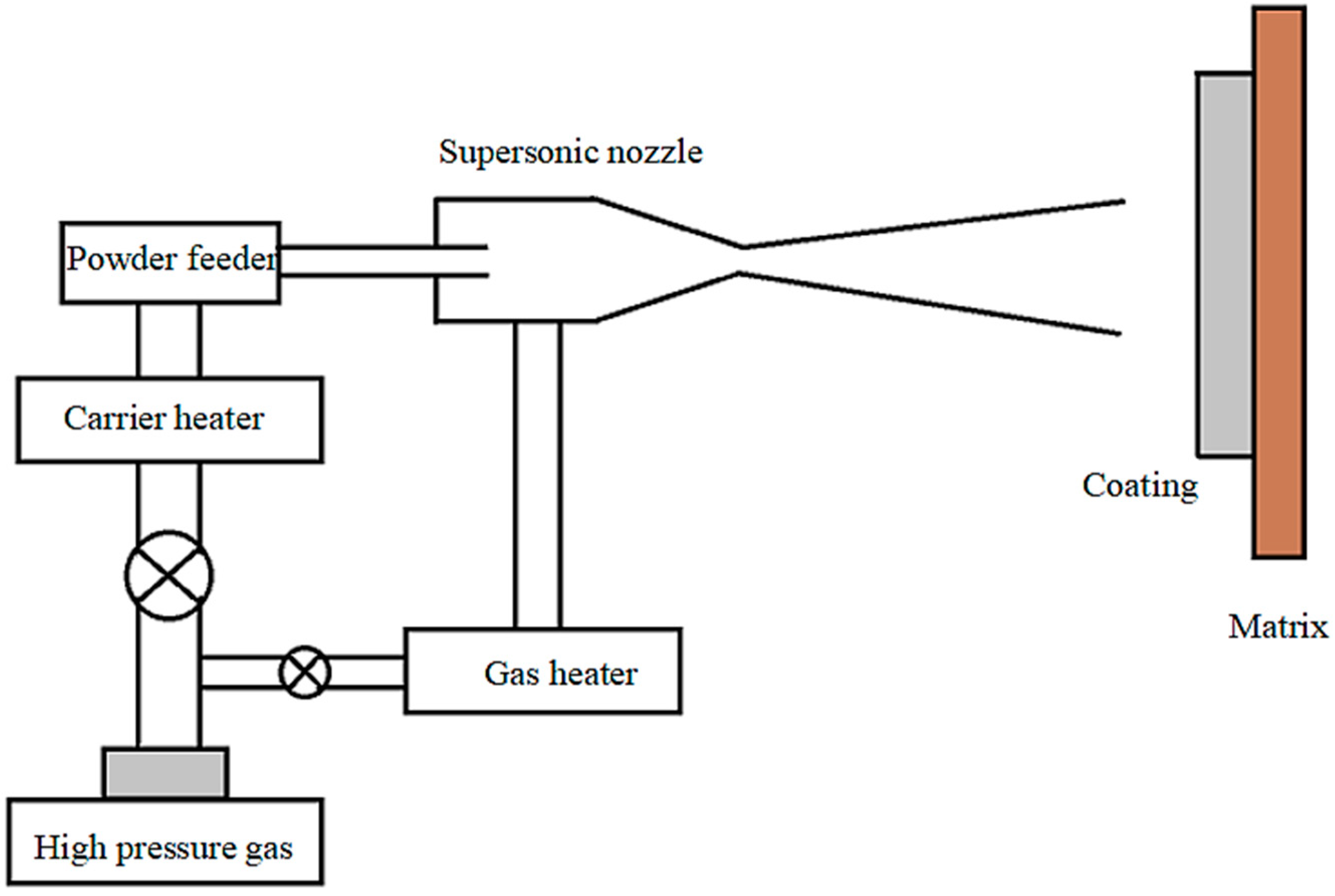
2.1. Preparation of Coating

Spherical powder particles of Zn, Mg, Al, and ZnO having sizes in the range of 10–30 μm were used to prepare the composite coatings. In order to synthesize the Zn65Al15Mg5ZnO15 and Zn45Al35Mg5ZnO15 coatings, the corresponding mass percentages of each component were mixed. Then they were mixed in a ball mill for 1.5 h to obtain uniform coating spraying materials. The matrix was made of 20 mm × 100 mm × 2 mm Q235 steel (Q235 is a carbon structural steel, also called level of steel. Q represents the yield limit of this material, and the latter 235 refers to the yield value of this material, which is around 235 MPa.). Before spraying, the surface of the Q235 steel was strengthened by sand blasting and descaling.
The composite coatings were prepared using a cold spraying technique (DyMET 423). The core of the cold spraying equipment is the spray gun mechanism, which is equipped with a high-pressure gas pipeline, heater, powder feeding pipeline, and de Laval nozzle (diameter 2 mm). The whole spray gun mechanism is installed on a six-degrees-of-freedom manipulator arm. The compressed power gas is nitrogen at the pressure of 1.8 MPa, and its working temperature is 400 °C. The distance between the spray gun and the spraying base is 20 mm, and the spraying speed of the powder particles is 800 m/s. Figure 1 is a schematic diagram of the working principle of the cold spray coating preparation.
The coatings were cut into 10 mm × 10 mm samples by laser cutting technology. The sample surface was polished repeatedly, then the impurities were removed by ultrasonic cleaning in absolute ethanol. Finally, the treated samples were stored in a vacuum bag for further tests.

2.2. Coating Characteristics

The microstructures of the composite coatings of Zn65Al15Mg5ZnO15 and Zn45Al35Mg5ZnO15 were observed and characterized. On the one hand, scanning electron microscopy (SEM, JSM-7610F, JEOL, Tokyo, Japan) provided information on the coating morphology and further summarized the microstructure characteristics of the coating. On the other hand, the elemental composition of the coating was characterized by an energy-dispersive X-ray spectroscopy (EDS) function of a scanning electron microscope (SEM). The parameters set by the scanning electron microscope to observe the microstructure of the coating areas was as follows: continuous scanning mode, scanning speed of 2°/min, scanning range of 10° to 90°, acceleration voltage of 20 kV, resolution of 1 nm, and so on.

2.3. Corrosion Behavior of the Composite Coatings

The neutral salt spray test (NSS, LRHS-108-RY, Shanghai Forestry Instrument Co., Ltd., Shanghai, China) was used to assess the corrosion behavior in the presence of a chloride aggressive environment. In order to assess the corrosion performance of the two composite coatings involving NSS, the selected specimens (area of 10 mm × 10 mm) were divided into four groups, each with four samples. The grouped samples were placed on the salt spray test box, waiting for the start of the neutral salt spray test. The parameters of the neutral salt spray test were as follows: 1000 mL of 3.5% ± 1.5% NaCl solution was placed into the spray chamber, the pH of the NaCl solution was between 6.5 and 7.2, the working temperature of the salt spray test chamber was stable at 35 ± 2 °C, the neutral salt spray test work process was static at room temperature, the NSS test for the investigated composite coatings had a total duration of 480 h, and intermediary examinations were performed after 120, 240, and 360 h of conditioning.
In addition, electrochemical accelerated tests were also performed using a 3.5% ± 1.5% NaCl solution, involving an electrochemical workstation (CHI604E, Shanghai Chenhua Instruments Co., Ltd., Shanghai, China). A three-electrode electrochemical cell was used, where Ag–AgCl (in saturated KCl) was the reference electrode, a Pt plate (10 mm × 10 mm) was the auxiliary electrode, and the composite coating sample was the working electrode. Prior to the electrochemical accelerated corrosion test, the non-coated surface of the coated sample was sealed with Kraft silicone rubber to prevent other surfaces affecting the coating test. The samples of the two composite coatings were divided into five labeled groups, and the labeled samples were separately placed in a 3.5% ± 1.5% NaCl solution where the solution was intermittently magnetically stirred every 12 h. The five groups of composite coating samples were soaked for 1, 120, 240, 360, and 480 h, respectively. The immersed composite coatings were placed in the electrochemical cell to measure their stable open circuit potential and corresponding polarization curves. The open circuit potential and polarization curves of each set of samples were measured multiple times to obtain good open circuit potential and plan curves. Then a Tafel curve test was performed at a scanning rate of 0.5 mV/s. A Butler–Volmer analysis involving Thales XT5.1.4 software was used to determine the corrosion current values (denoted Icorr) for each investigated working electrode. In addition, the polarization curves of Q235 matrix steel were compared with those of Zn65Al15Mg5ZnO15 and Zn45Al35Mg5ZnO15 composite coatings.

2.4. Photocatalytic Characteristics of the Composite Coatings

The photocatalytic degradation characteristics of Zn65Al15Mg5ZnO15 composite coating, Zn45Al35Mg5ZnO15 composite coating, and matrix steel Q235 on methyl blue were studied by UV spectrophotometer (UV-5100, Shanghai Yuanfang Instrument Co., Ltd., Shanghai, China). Samples were placed in a beaker containing methyl blue solution with a concentration of 100 mL and 20 mg/L. Ultraviolet light was directly irradiated on the coating surface. In the experiment, a magnetic stirrer (CL-200, Gongyi Yuhua Instrument Co., Ltd, Zhengzhou, China) was used to stir the solution continuously to prevent degradation products remaining on the coating surface from affecting the sustainability of degradation. Every 5 or 10 min, the pipette was used to put 3 mL solution into the colorimetric tube. The absorbance of the solution was measured by ultraviolet spectrophotometer, and the concentration of methyl blue in each time period was obtained. When degrading, the ultraviolet light should be irradiated on the surface of the coating as much as possible to ensure that the degradation efficiency of the coating is not affected. A comparative analysis of the photodegradation of methyl blue under UV irradiation on the investigated composite coatings and on Q235 steel was performed.
The degradation rate was calculated using Equation (1) below. The degradation rate of methyl blue under different materials was calculated by photocatalytic degradation test data.
η = (A0 − At)/A0 × 100%
where η is the degradation rate, A0 is the initial absorbance of the maximum absorption peak of the methyl blue solution, and At is the absorbance of the maximum absorption peak at the time, t, of the methyl orange solution.

2.5. Composite Coating Friction and Wear Test

The friction and wear characteristics of the investigated composite coating were tested by a friction and wear tester (MFT-50, Rtec Instruments, San Jose, CA, USA). The friction mode adopts spherical reciprocating wet friction, wherein the friction pair (the workpiece to be ground) is a GCr15 bearing steel ball (MFT-50, Rtec Instruments, San Jose, CA, USA) having a diameter of 6.35 mm. The relevant parameters were set according to the conditions of the material of the composite coating. The reciprocating friction frequency was 4 Hz, the grinding stroke was 4.50 mm, the friction and wear positive pressure was 20 N, and the friction and wear test time was 90 min. The entire friction and wear test was carried out in a 3.5% NaCl solution environment with a relative humidity of 45% ± 5%. The 3D morphology characterizing the frictional wear surface was observed using a white light interferometer (MFT-5000, Rtec Instruments, San Jose, CA, USA). The samples were weighed separately before and after the friction and wear test, and the wear and wear rates of the samples were calculated.

3. Results and Discussion

3.1. Preparation of Composite Coatings

Figure 2 presents the images of the Zn65Al15Mg5ZnO15 and Zn45Al35Mg5ZnO15 composite coated sheets prepared by cold spraying technology. It can be observed that the surfaces of the composite coated plates of Zn65Al15Mg5ZnO15 and Zn45Al35Mg5ZnO15 are very smooth and uniform. However, it can also be seen that the surface of the Zn65Al15Mg5ZnO15 composite coating has obvious pits and defects. After several sprays, the Zn65Al15Mg5ZnO15 composite coating still had obvious pits and defects, whereas the surface of the Zn45Al35Mg5ZnO15 composite coating was very flat and smooth, and the coating surface had no obvious defects. By comparing the macroscopical appearance of the Zn65Al15Mg5ZnO15 and Zn45Al35Mg5ZnO15 composite coatings prepared by cold spraying, it was found that the spraying deposition effect of Zn45Al35Mg5ZnO15 was superior to that of Zn65Al15Mg5ZnO15.

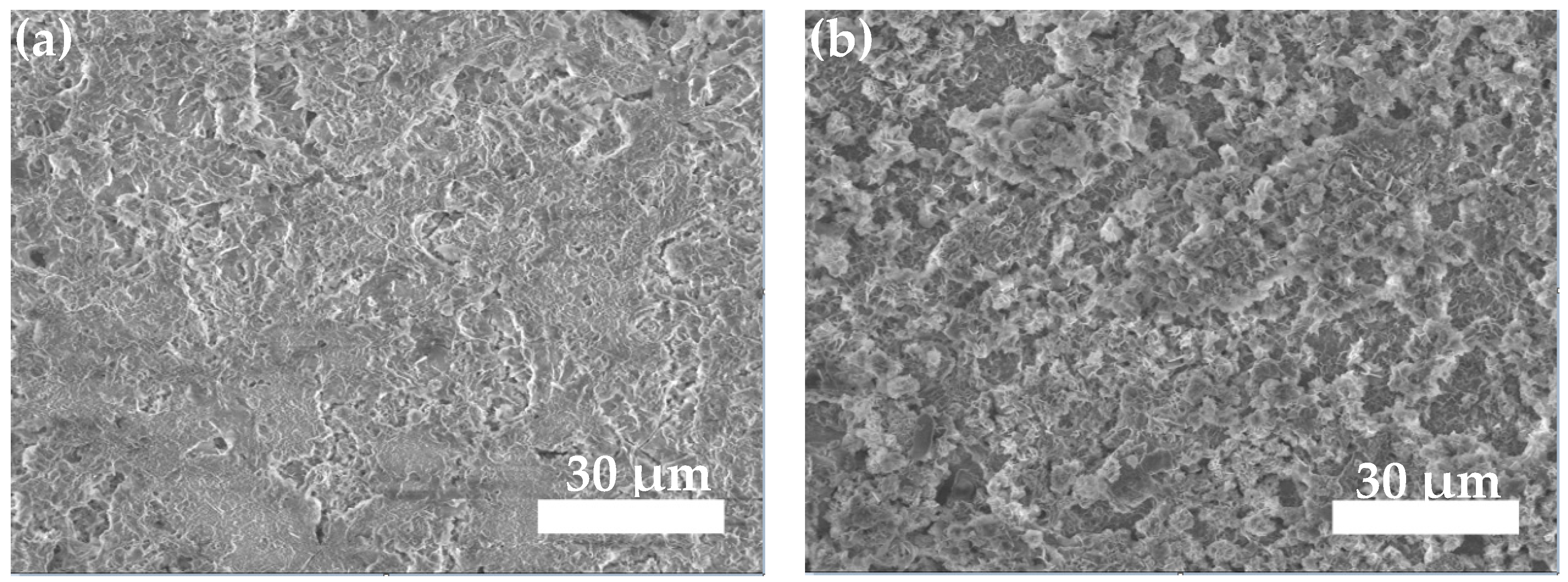
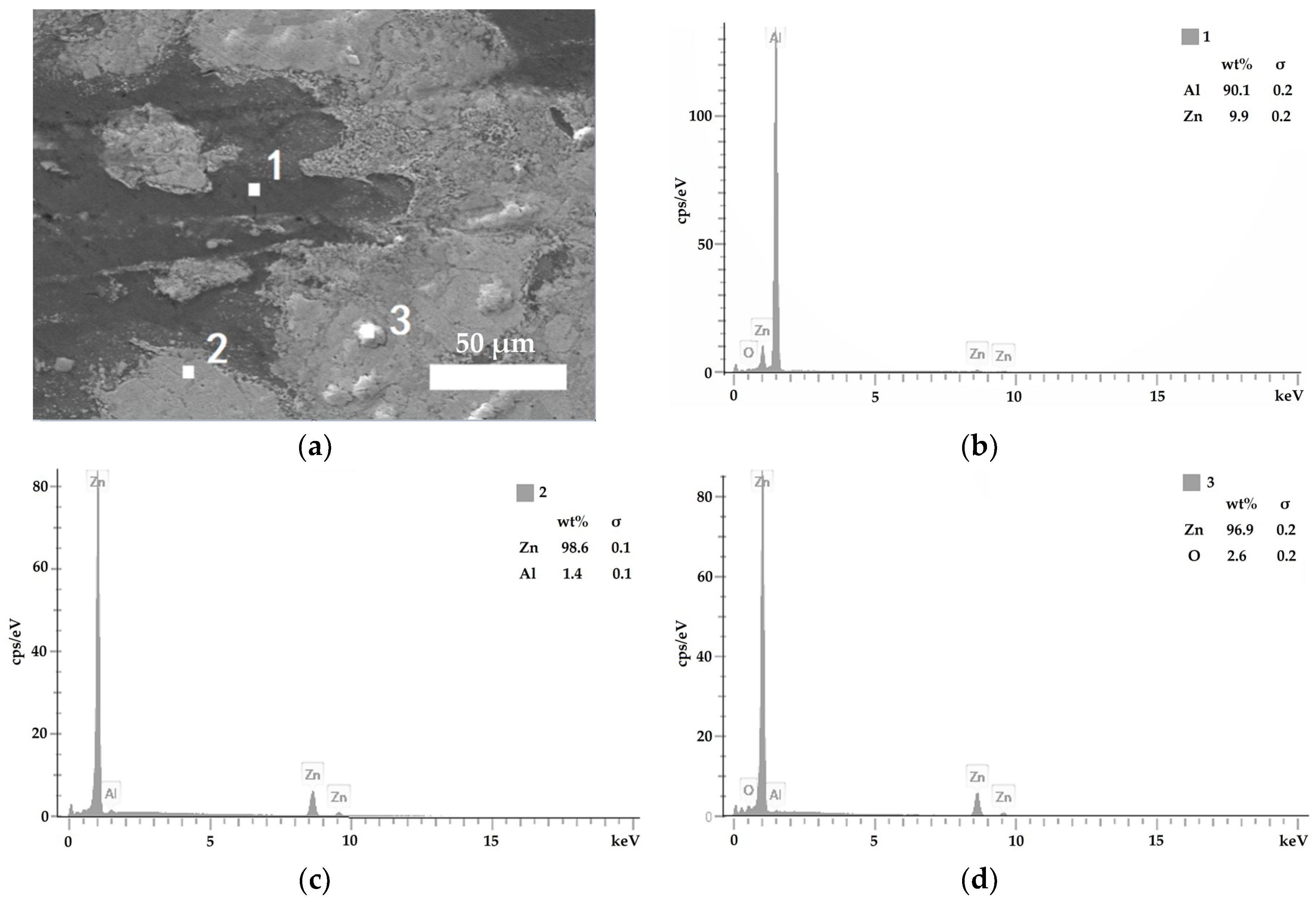
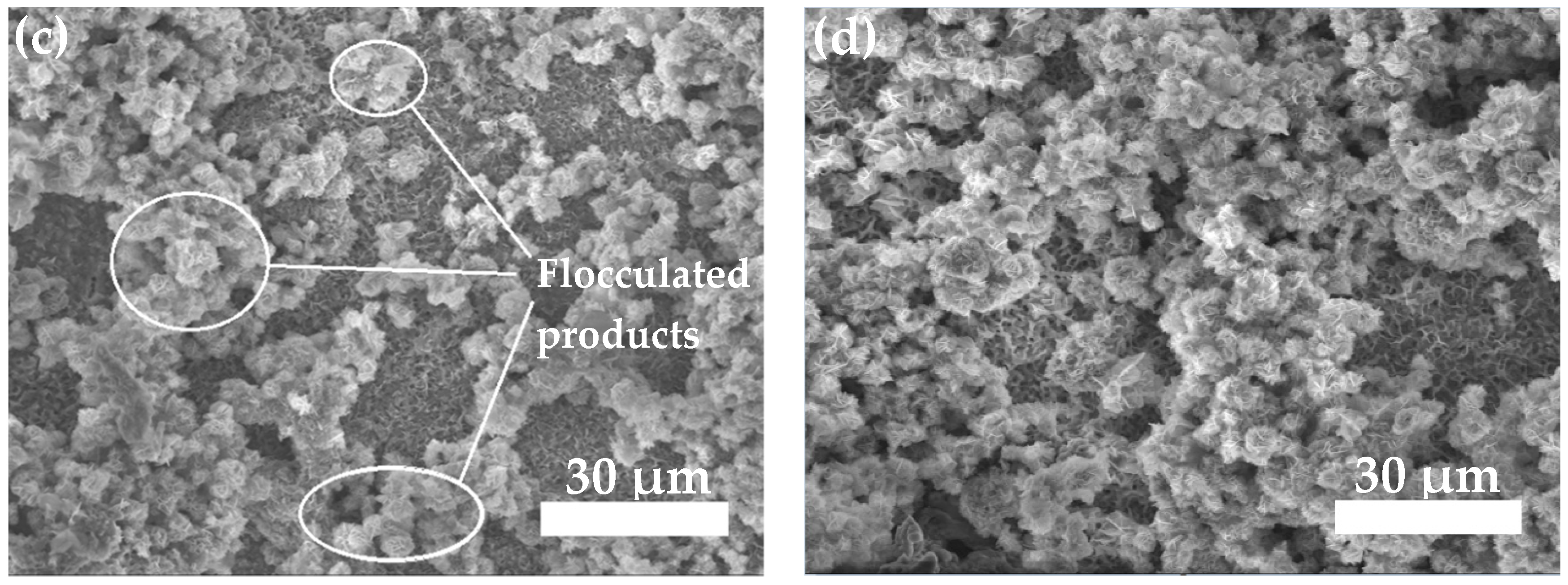
3.2. Composite Coating Morphology

Figure 3 shows the morphology of the surface of typical Zn45Al35Mg5ZnO15 and Zn65Al15Mg5ZnO15 composite coatings. There are three main morphology characteristics of the composite coatings: bright spots and white and black regions. Figure 3a,d is the enlarged 300× micromorphology of the composite coatings, Figure 3b,e is the enlarged 3000× micromorphology of the composite coatings, and Figure 3c,f is the enlarged 300× micromorphology of the cross-section of the composite coatings. Figure 3 shows the micromorphology of the composite coatings. The composite coatings have three main components, which are uniformly distributed in the coatings, and the same appearance does not have a large amount of aggregation. It is further explained that the mechanical mixing of cold sprayed coatings Zn, Al, Mg, and ZnO is very uniform in the configuration process. Combining the micromorphology and micro cross-sectional structure of the two composite coatings, it was found that the three morphology characteristics were uniform strips and closely adhered to each other to form a compact coating. There were no obvious defects, such as pits, in the internal structure of the composite coatings.
Figure 4 and Figure 5 present the energy dispersion point spectra of the three kinds of composite elements in the microstructures of the Zn45Al35Mg5ZnO15 and Zn65Al15Mg5ZnO15 composite coatings. Figure 4a and Figure 5a show the microstructures of the two composite coatings magnified 3000×. Figure 4b–d and Figure 5b–d are the energy-dispersive spectra of Points 1, 2, and 3 corresponding to the three appearances of the composite coating surface, respectively. Energy is the element content of a point represented by a dispersion spectrogram. By comparing the energy dispersion spectra of the two layers in Figure 4 and Figure 5, it was found that they have similarity in structure, morphology, and element content. The elemental composition of Points 1, 2, and 3 was substantially similar, so the components of the two coatings were analyzed together. In Figure 4b and Figure 5b, the Al content in Point 1 is 91.8% and 90.1%, and the Zn content is only 8.2% and 9.9%, so the element of the black region in the overcoat layer could be analyzed. The Zn content in Point 2 in Figure 4c and Figure 5c is 98.8% and 98.6%, but the Al content is only 1.2% and 1.4%, so the white area in the composite coating could be obtained by elemental content analysis. The element is Zn. Figure 4d and Figure 5d contain only Zn and O elements, so the element in the bright spot area is ZnO.
Through the analysis and observation of two kinds of composite coatings from two perspectives (plane and cross-section), shown in Figure 3, it was found that obvious plastic deformation occurs in the preparation of powder coatings and that the overall structure is flat. The structure of the composite coating is compact, and there are no pits and defects in the surface or internal structure.

3.3. Corrosion Resistance Test

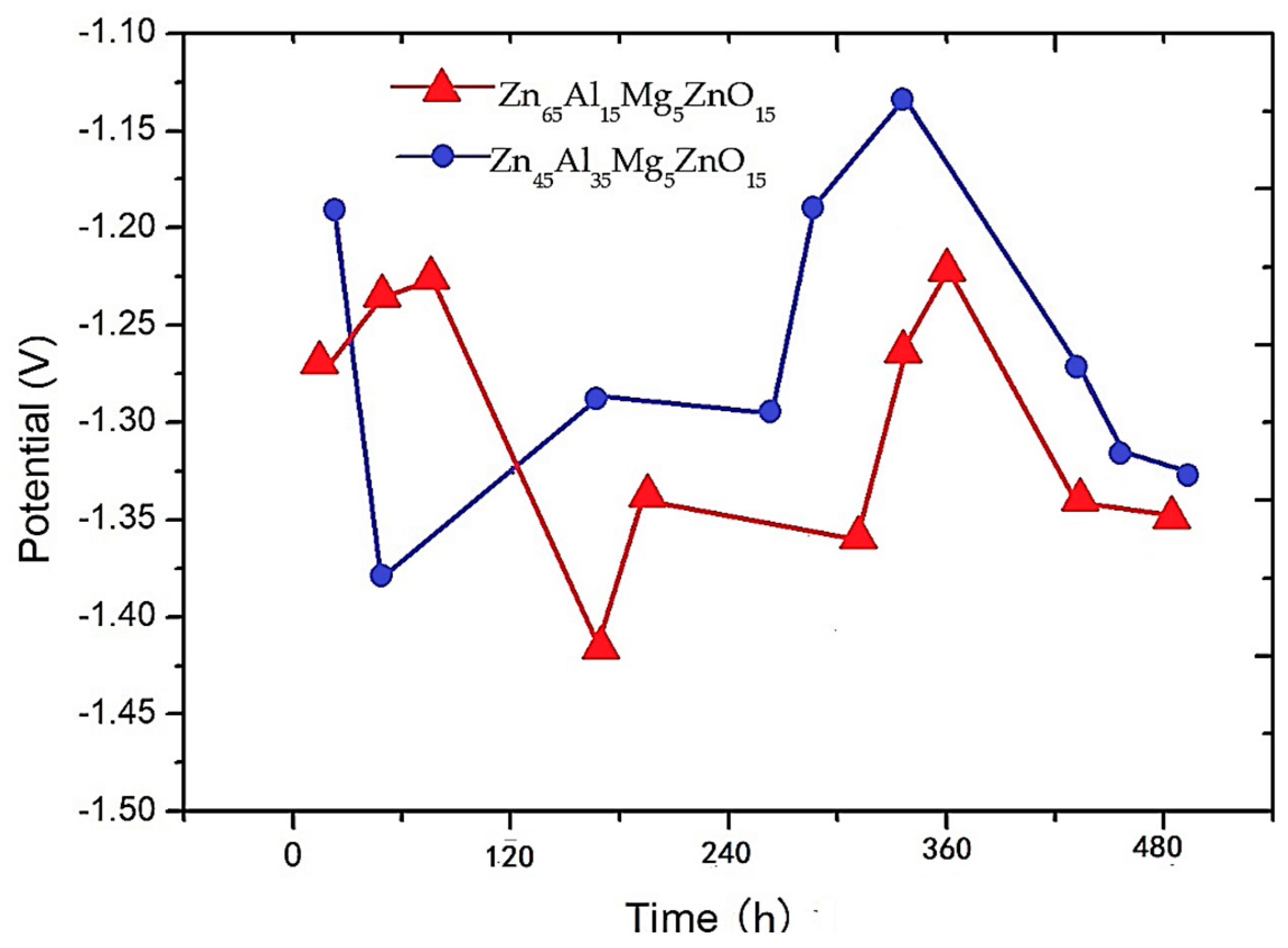
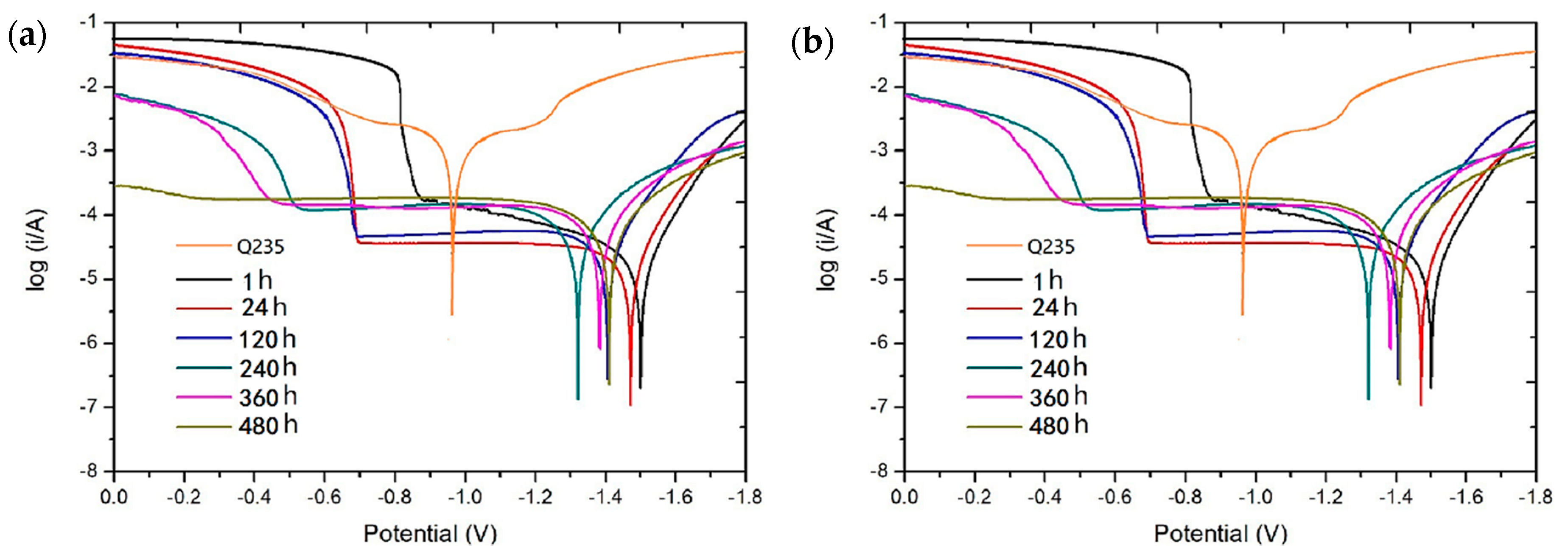
3.3.1. Electrochemical Accelerated Corrosion Test

The dependence of the open circuit potential against time provides information on corrosion evolution. The displacement of the corrosion potential toward more electronegative values suggests an increase in the corrosion rate. Figure 6 presents the evolution of the open circuit potential against the time for the two investigated composite coatings. Figure 6 shows the more negative displacement of the potential of the two composite coatings at the onset of corrosion. When the etching time is 120 h, the corrosion open circuit potential of the coating gradually shifts to the positive direction until it is maximum. After 360 h, the open circuit potentials of the two composite coatings began to shift in the negative direction. During the whole corrosion process, the corrosion process of the Zn65Al15Mg5ZnO15 and Zn45Al35Mg5ZnO15 composite coatings was basically the same, and the open circuit potential was synchronously shifted in the positive direction or negative direction. However, when the corrosion is stable, the open circuit potential of the Zn45Al35Mg5ZnO15 composite coating is always displaced in the positive direction of the Zn65Al15Mg5ZnO15 composite coating.
Figure 7 shows the polarization curves of the two kinds of composite coatings at 1, 24, 120, 240, 360, and 480 h and the polarization curves of matrix steel Q235. Table 1 shows the values of the corrosion potential and of the corrosion current density for the two composite coatings at 1, 120, 360, and 480 h and the polarization potential and corrosion current density of Q235. Figure 7a is a comparison of the polarization curves of the Zn45Al35Mg5ZnO15 composite coating at different times and the planned curve of the matrix steel. It was found that the polarization potential of the Zn45Al35Mg5ZnO15 composite coating at different times (maximum −1.32 V) is always much smaller than that of the base steel Q235. The polarization potential (−0.95 V) reveals that the Zn45Al35Mg5ZnO15 composite coating has a strong anodizing protection of the base steel in a seawater environment. Figure 7b is a comparison of the polarization curves of the Zn65Al15Mg5ZnO15 composite coating at different times and the planned curve of the matrix steel. It was found that the polarization potential of the Zn65Al15Mg5ZnO15 composite coating at different times (maximum −1.22 V) is always much smaller than the base steel Q235. The polarization potential (−0.95 V) shows that the Zn65Al15Mg5ZnO15 composite coating also has strong anodized protective base steel properties in the seawater environment. By comparing the corrosion current densities of the two composite coatings in Table 1, it was found that the corrosion current density of the Zn65Al15Mg5ZnO15 composite coating is higher than that of the Zn45Al35Mg5ZnO15 composite coating under the same corrosion time. In other words, the corrosion rate of the Zn45Al35Mg5ZnO15 composite coating always displaced in the more positive direction as compared to the Zn65Al15Mg5ZnO15 composite coating.
Based on the data of Table 1 and Figure 6 and Figure 7, it was found that both the Zn65Al15Mg5ZnO15 and Zn45Al35Mg5ZnO15 composite coatings have good properties of anodic oxidation protection of matrix steel. However, the open circuit potential and corrosion current density show that the anodic oxidation rate of the Zn65Al15Mg5ZnO15 composite coating is always higher than that of the Zn45Al35Mg5ZnO15 composite coating. Therefore, considering the time effect of protecting matrix steel, the composite coating of Zn45Al35Mg5ZnO15 has a longer durability than that of Zn65Al15Mg5ZnO15 under the same coating conditions.

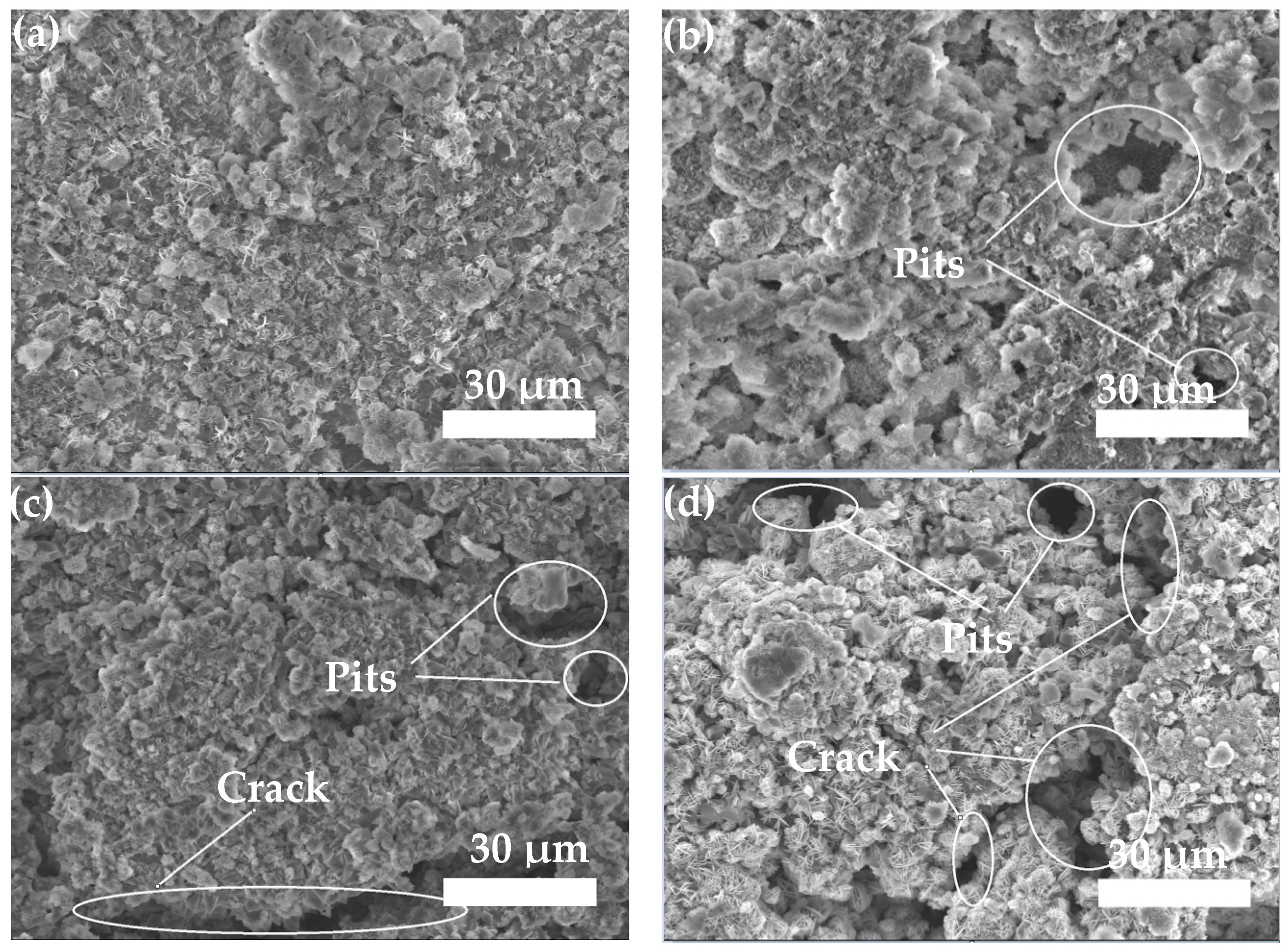
3.3.2. Neutral Salt Spray Test of Composite Coating

Figure 8 presents the SEM micrographs of the Zn45Al35Mg5ZnO15 composite coatings after different conditioning periods. Figure 8a shows the micromorphology of the composite coating after 120 h of corrosion. A dense network morphology is formed on the surface of the coating after corrosion. Figure 8b shows the micromorphology of the composite coating after 240 h of corrosion. The surface of the coating is corroded to form a dense flocculent corrosion product. The interior of the corrosion product is a lamellar material. Figure 8c shows the micromorphology of the composite coating after 360 h of corrosion. The flocculent morphology products on the surface of the coating are gradually eroded away, and the second layer of the dense flocculent morphology is formed by corrosion. Figure 8d shows the micromorphology of the composite coating after 480 h of corrosion, and the flocculent structure on the surface of the coating continues to corrode. The results show that the corrosion of the Zn45Al35Mg5ZnO15 composite coating is regularly stratified and that there are no pits and cracks in the corrosion process.
Figure 9 presents the SEM micrographs of the Zn65Al15Mg5ZnO15 composite coatings after different conditioning periods. Figure 9a shows the micromorphology of the composite coating after 120 h of corrosion. The surface of the coating is corroded to form a dense flocculent corrosion product. The interior of the corrosion product is a lamellar material. Figure 9b shows the micromorphology of the composite coatings after 240 h of corrosion. The deeper coatings begin to corrode irregularly, and deep pits appear on the surface of the corrosion products. Figure 9c shows the micromorphology of the composite coating after 360 h of corrosion. The surface of the coating is etched and cracks and pits appear. Figure 9d shows the micromorphology of the composite coating etched for 480 h—the surface of the coating is severely corroded and severe cracks and pits appear. The results show that the corrosion of the Zn65Al15Mg5ZnO15 composite coating is not uniform and that deep pits and cracks are produced after 240 h of corrosion.
Figure 8 and Figure 9 show that the Zn45Al35Mg5ZnO15 composite coating has regular delamination corrosion and that no pits and crack defects occur during the corrosion process. The Zn65Al15Mg5ZnO15 composite coating is not uniformly etched and defects, such as pits and cracks, appear. Therefore, the Zn45Al35Mg5ZnO15 composite coating has a better corrosion resistance than the Zn65Al15Mg5ZnO15 composite coating under the same corrosion conditions.
Figure 10 is the composition analysis of corrosion products of Zn65Al15Mg5ZnO15 and Zn45Al35Mg5ZnO15 by X-ray diffraction. It shows that the corrosion products of the two composite coatings are basically similar. The main corrosion products are (Al2O3)4·H2O, Zn5(OH)8Cl2·H2O, and Zn(OH)2. The main ion reaction is as follows:
Cathodic reaction: O2 + 2H2O + 4e → 4OH
Oxidation of metallic zinc: Zn − 2e → Zn2+
Hydrolysis of zinc ions: Zn2+ + 2H2O → Zn(OH)2 + 2H+
The corrosion rate of the two composite coatings becomes slower throughout the corrosion process, and then the corrosion rate becomes faster. Due to the corrosion rate of the coating being relatively fast at first, the corrosion of the coating produces surface oxidation of the oxidation product, which slows down the corrosion rate. When the passivation film is etched, the coating continues to be etched, so the corrosion rate is increased. The entire corrosion process is repeated, and it is known that the coating has been etched.
The corrosion resistance test data show that the Zn65Al15Mg5ZnO15 and Zn45Al35Mg5ZnO15 composite coatings both have an acceptable corrosion resistance but that the Zn45Al35Mg5ZnO15 composite coatings have a superior corrosion resistance and durability to the Zn65Al15Mg5ZnO15 composite coatings.

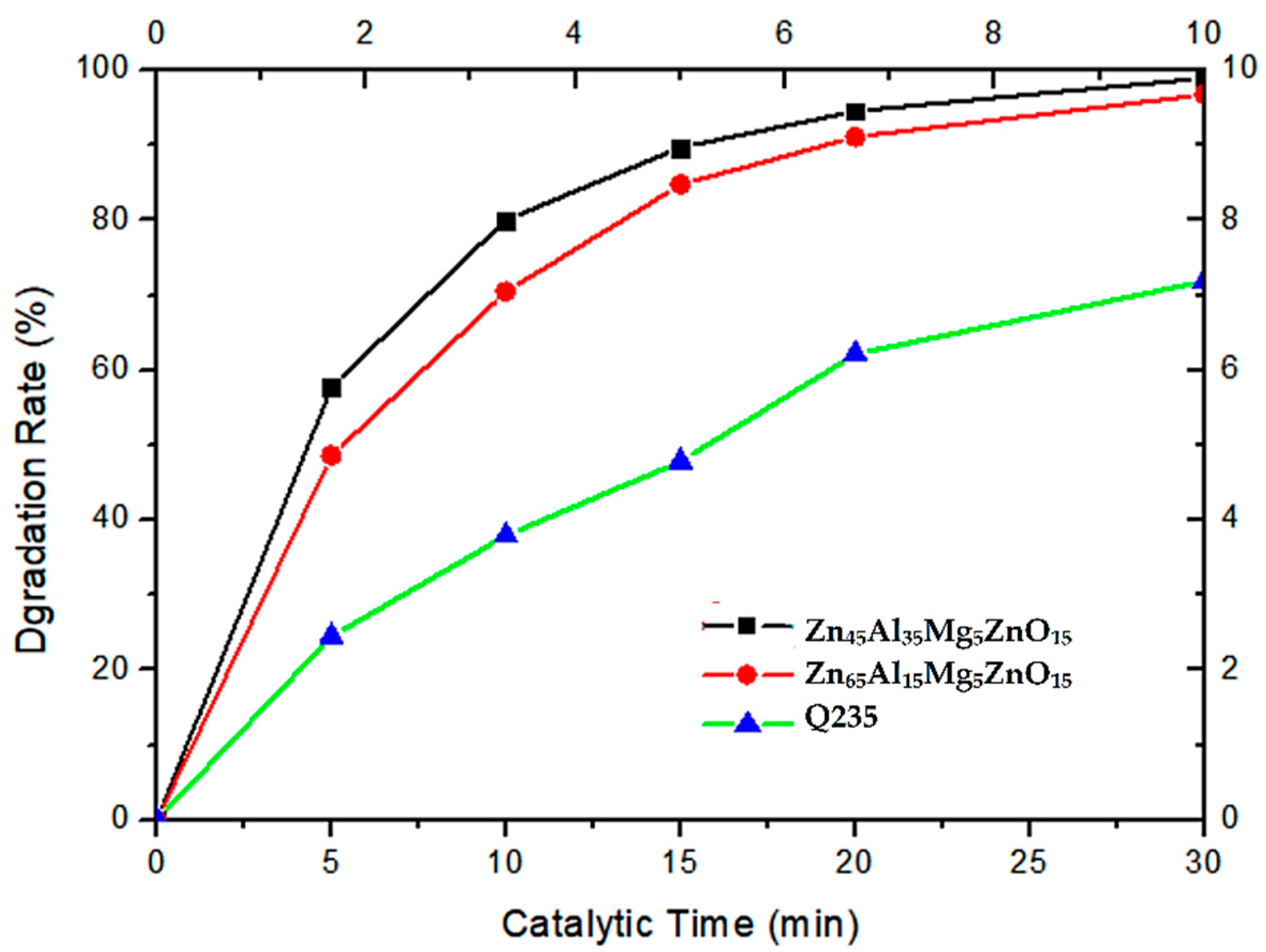
3.4. Photocatalytic Degradation of Methyl Blue

Table 2 and Figure 11 are the results of degradation of methyl blue solution by the Zn65Al15Mg5ZnO15 composite coating, the Zn45Al35Mg5ZnO15 composite coating, and the matrix steel Q235 under ultraviolet irradiation. Table 2 shows that the absorbance of methyl blue is the fastest under the action of the Zn45Al35Mg5ZnO15 composite coating and that the fading rate of methyl blue degradation solution is also the fastest. The absorbance of methyl blue is the slowest under the action of Q235, and the fading rate of methyl blue degradation solution is the slowest. The peak data of methyl blue absorbance were calculated to obtain the degradation rate of methyl blue. Figure 11 shows that the Zn65Al15Mg5ZnO15 composite coating and the Zn45Al35Mg5ZnO15 composite coating degrade methyl blue faster than Q235. In the same time, the degradation rate of the Zn45Al35Mg5ZnO15 composite coating to methyl blue was 98.9%, the degradation rate of methyl blue by the Zn65Al15Mg5ZnO15 composite coating was 96.7%, and the degradation rate of methyl blue by Q235 was only 71.8%.
The methyl blue degradation test data show that the degradation rates of methyl blue by the Zn65Al15Mg5ZnO15 composite coating and the Zn45Al35Mg5ZnO15 composite coating were much faster than that of Q235 and that the coatings have good photocatalytic degradation. The degradation efficiency of the Zn45Al35Mg5ZnO15 composite coating on methyl blue is better than that of the Zn65Al15Mg5ZnO15 composite coating.

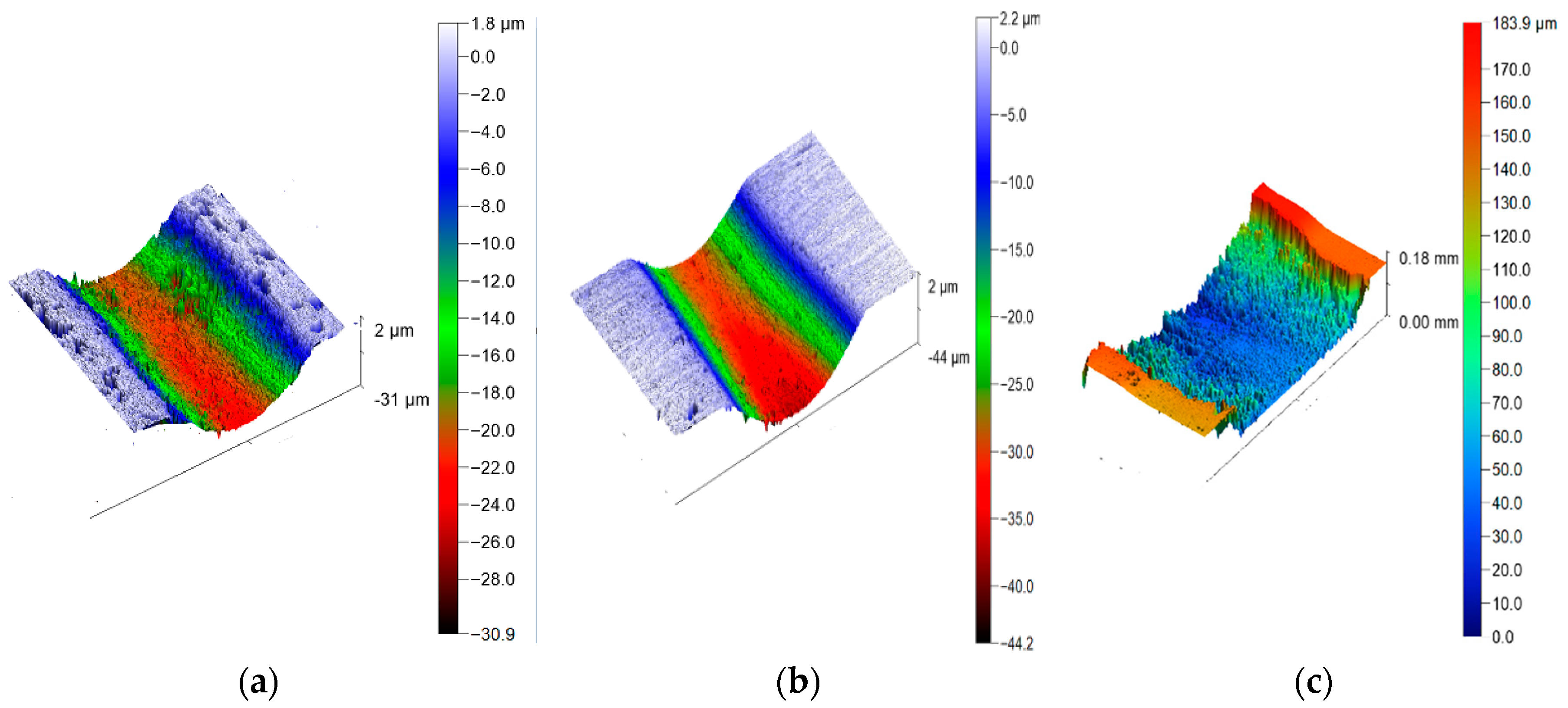
3.5. Friction and Wear Test of Composite Coatings

Figure 12 shows the friction and wear of the Zn65Al15Mg5ZnO15 composite coating, the Zn45Al35Mg5ZnO15 composite coating, and the base steel Q235 under the same conditions. Figure 12a shows the appearance of the Zn45Al35Mg5ZnO15 composite coating after friction and wear, and the depth of the wear scar is 28 ± 1 μm. Figure 12b shows the appearance of the Zn45Al35Mg5ZnO15 composite coating after friction and wear, and the depth of the wear scar is 44 ± 1 μm. Figure 12c shows the appearance of the Q235 steel after friction and wear, and the depth of the wear scar is 180 ± 5 μm. It can be seen that the wear marks of the Zn45Al35Mg5ZnO15 composite coatings are the shallowest, followed by the Zn65Al15Mg5ZnO15 composite coatings, and the wear marks of the Q235 matrix steel are the deepest.
Table 3 shows the friction and wear data of Zn65Al15Mg5ZnO15, Zn45Al35Mg5ZnO15, and base steel Q235. Table 3 shows that the friction and wear coefficient of the Zn45Al35Mg5ZnO15 composite coating is 0.181, and the amount of wear is 0.0035 g. The friction and wear coefficient of the Zn65Al15Mg5ZnO15 composite coating is 0.231 and the wear amount is 0.0050 g. The base steel Q235 has a friction and wear coefficient of 0.358 and a wear amount of 0.0111 g. By comparing the three groups of experimental data, it can be seen that the friction coefficient and wear amount of the Zn45Al35Mg5ZnO15 composite coating are the smallest and that its wear resistance is the best.
Figure 12 and Table 3 show that the Zn65Al15Mg5ZnO15 composite coating and the Zn45Al35Mg5ZnO15 composite coating have better friction and wear resistance than the base steel Q235, and the Zn45Al35Mg5ZnO15 composite coating has the best friction and wear characteristics.

4. Conclusions

Two types of Zn–Al–Mg/ZnO composite coatings were successfully prepared on Q235 metallic substrate involving the cold spray technique. The obtained coatings were investigated from corrosion performance, photocatalytic degradation, and wear resistance viewpoints. The following conclusions can be drawn:
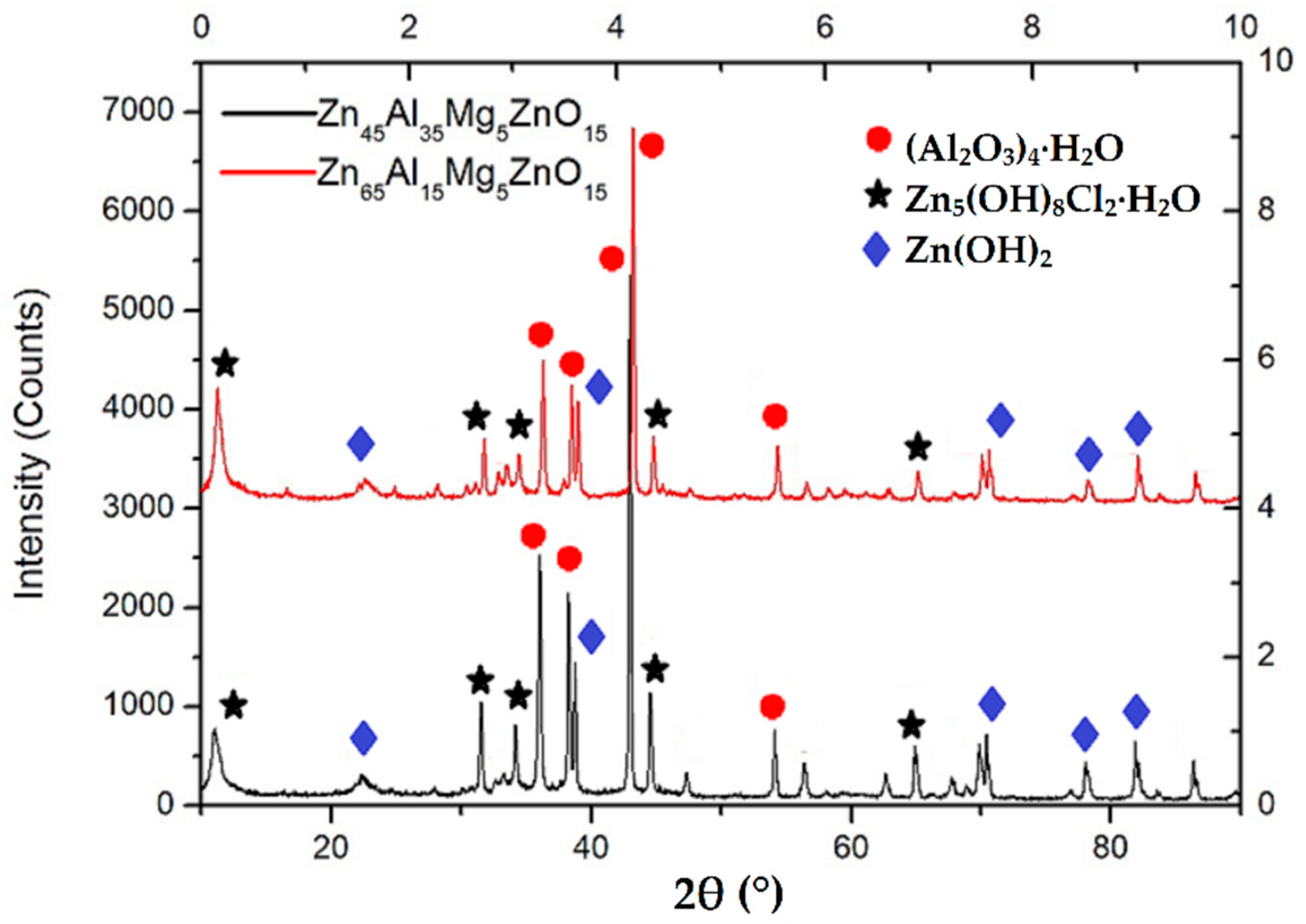
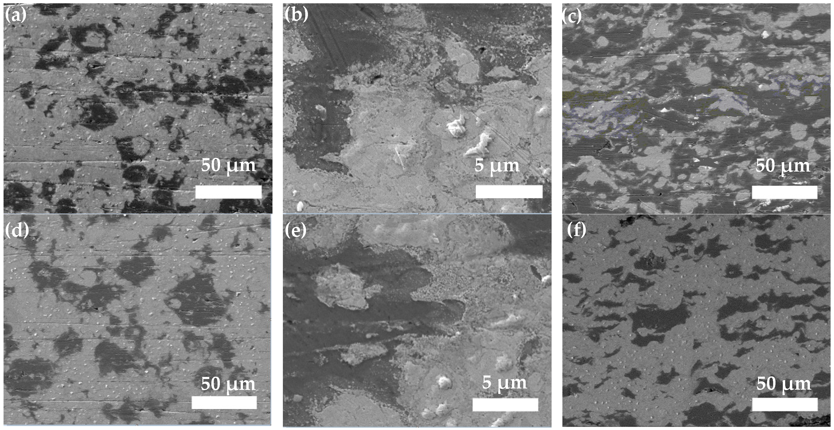
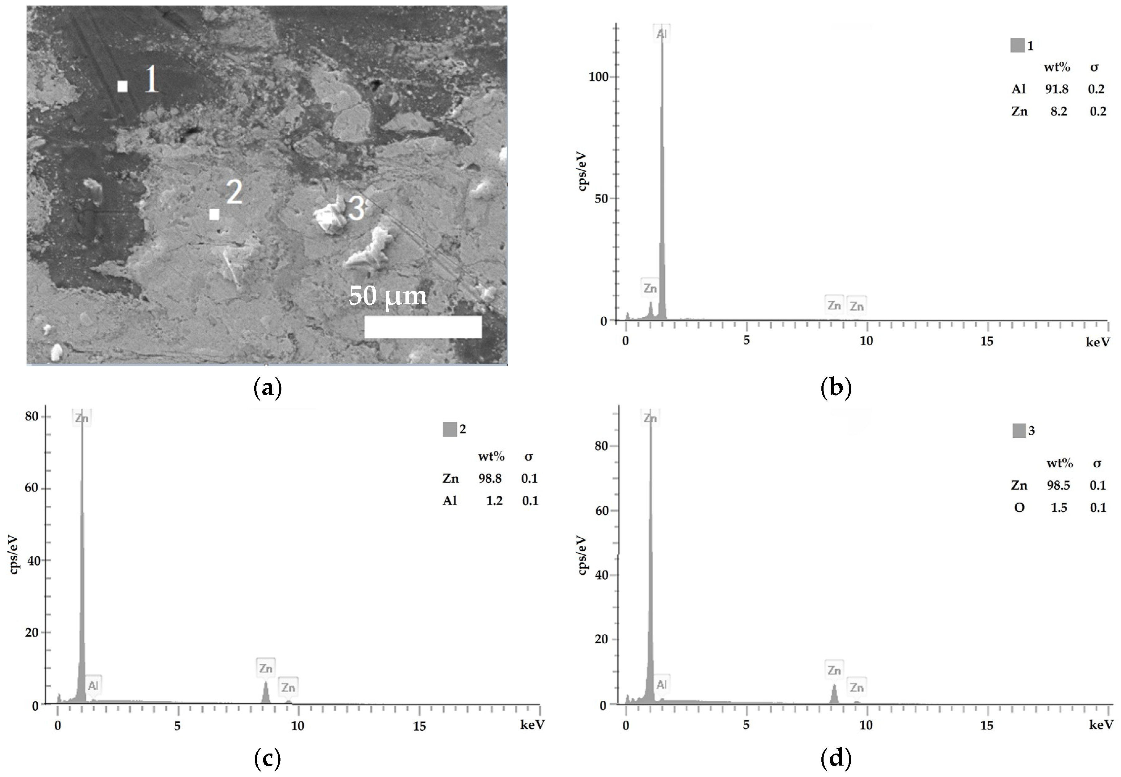
  • Zn65Al15Mg5ZnO15 composite coating and Zn45Al35Mg5ZnO15 composite coating can be prepared on base steel Q235 by cold spray technique. The surface of the Zn45Al35Mg5ZnO15 composite coating is smoother and flatter than the Zn65Al15Mg5ZnO15 composite coating. The micromorphology of the two composite coatings prepared by cold spraying is dense, there are no defects such as voids inside the coating, and the Zn, Al, Mg, and ZnO elements inside the coating are uniformly distributed.
  • The analysis of electrochemical workstation test data shows that both the Zn65Al15Mg5ZnO15 and Zn45Al35Mg5ZnO15 composite coatings have strong anodic oxidation cathodic protection characteristics, which can protect the matrix steel Q235 from corrosion. The open circuit potential and polarization current of the two composite coatings at different time periods show that the corrosion rate of the Zn65Al15Mg5ZnO15 composite coating is higher than that of the Zn45Al35Mg5ZnO15 composite coating, and the corrosion products produced by the oxidation of the composite coating have corrosion slowing characteristics during corrosion.
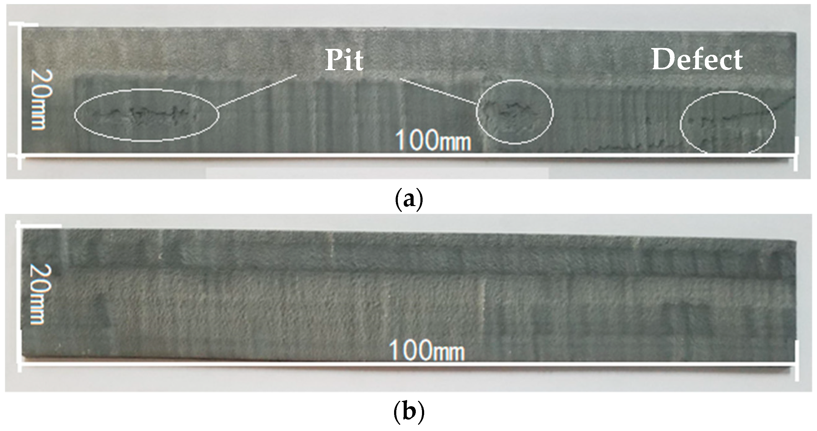
  • The neutral salt spray test of the two composite coatings shows that the Zn45Al35Mg5ZnO15 composite coating experienced regular delamination corrosion with no pits or cracks defects but the Zn65Al15Mg5ZnO15 composite coating was unevenly corroded and had a deep corrosion, with defects such as pits and cracks, after 240 h of corrosion. The corrosion resistance test shows that the Zn45Al35Mg5ZnO15 composite coating has a better corrosion resistance and long-term stability than the Zn65Al15Mg5ZnO15 composite coating.
  • By comparing the photocatalytic degradation data of the Zn65Al15Mg5ZnO15 composite coatings, Zn45Al35Mg5ZnO15 composite coatings, and Q235 matrix steel for methyl blue solution, the results show that the two composite coatings have good photocatalytic properties but that the photocatalytic properties of the Zn45Al35Mg5ZnO15 composite coatings are better.
  • The results of the friction and wear tests show that both the Zn65Al15Mg5ZnO15 composite coating and the Zn45Al35Mg5ZnO15 composite coating have better friction and wear resistance than the base steel Q235 and that the friction and wear properties of the Zn45Al35Mg5ZnO15 composite coating are the best.
  • The results of all the above experiments show that the Zn45Al35Mg5ZnO15 composite coating prepared by cold spraying has a superior deposition effect, high photocatalytic efficiency, better corrosion resistance, and wear resistance.

Author Contributions

Conceptualization, S.W.; methodology, X.L. and S.W.; validation, X.L. and G.W.; data curation, S.W. and X.L.; writing—original draft preparation, X.L.; writing—review and editing, S.W. and D.W.; supervision, T.X. and H.D.; project administration, S.W.

Funding

This research was funded by the National Natural Science Foundation of China (No. 51872122), the Shandong Key Research and Development Plan, China (No.: 2016JMRH0218), and the Taishan Scholar Engineering Special Funding (2016–2020).

Conflicts of Interest

The authors declare no conflict of interest.

References

  1. Yan, S.K.; Song, G.L.; Li, Z.X.; Wang, H.N.; Zheng, D.J.; Cao, F.Y.; Horynova, H.; Dargusch, M.S.; Zhou, L. A state-of-the-art review on passivation and biofouling of Ti and its alloys in marine environments. J. Mater. Sci. Technol. 2018, 34, 421–435. [Google Scholar] [CrossRef]
  2. Chavan, N.M.; Kiran, B.; Jyothirmayi, A.; Phani, P.S.; Sundararajan, G. The corrosion behavior of cold sprayed zinc coatings on mild steel substrate. J. Therm. Spray Technol. 2013, 22, 463–470. [Google Scholar] [CrossRef]
  3. Olakanmi, E.O.; Doyoyo, M. Laser-assisted cold-sprayed corrosion-and wear-resistant coatings: A review. J. Therm. Spray Technol. 2014, 23, 765–785. [Google Scholar] [CrossRef]
  4. Cai, M.R.; Guo, R.S.; Zhou, F.; Liu, W.M. Lubricating a bright future: Lubrication contribution to energy saving and low carbon emission. Sci. China Technol. Sci. 2013, 56, 2888–2913. [Google Scholar] [CrossRef]
  5. Cui, H.; Li, N.; Peng, J.; Yin, R.; Li, J.; Wu, Z. Investigation on the thermal performance of a novel spray tower with upward spraying and downward gas flow. Appl. Energy 2018, 231, 12–21. [Google Scholar] [CrossRef]
  6. Gkomoza, P.; Lampropoulos, G.S.; Vardavoulias, M.; Pantelis, D.I.; Karakizis, P.N.; Sarafoglou, C. Microstructural investigation of porous titanium coatings, produced by thermal spraying techniques, using plasma atomization and hydride-dehydride powders, for orthopedic implants. Surf. Coat. Technol. 2019, 357, 947–956. [Google Scholar] [CrossRef]
  7. Wu, Y.N.; Ke, P.L.; Wang, Q.M.; Sun, C.; Wang, F.H. High temperature properties of thermal barrier coatings obtained by detonation spraying. Corros. Sci. 2004, 46, 2925–2935. [Google Scholar] [CrossRef]
  8. Pawłowski, L. Strategic oxides for thermal spraying: Problems of availability and evolution of prices. Surf. Coat. Technol. 2013, 220, 14–19. [Google Scholar] [CrossRef]
  9. Xie, X.; Chen, C.; Xie, Y.; Aubry, E.; Ren, Z.; Ji, G.; Liao, H. Comparative investigation of microstructure and properties of Ni-coated FeSiAl soft magnetic composite coatings produced by cold spraying and HVOF. Surf. Coat. Technol. 2019, 371, 224–234. [Google Scholar] [CrossRef]
  10. Hunter, B.; Aldwell, B.; Jenkins, R.; Lupoi, R. A study on the feasibility of laser annealing to relieve residual stresses in cold spray coatings. Procedia CIRP 2018, 78, 91–96. [Google Scholar] [CrossRef]
  11. Xie, Y.C.; Chen, C.Y.; Planche, M.P.; Deng, S.H.; Huang, R.Z.; Ren, Z.M.; Liao, H.L. Strengthened peening effect on metallurgical bonding formation in cold spray additive manufacturing. J. Therm. Spray Technol. 2019, 28, 769–779. [Google Scholar] [CrossRef]
  12. Chen, C.Y.; Xie, Y.C.; Yin, Y.S.; Fukanuma, H.; Huang, R.Z.; Zhao, R.X.; Wang, J.; Ren, Z.G.; Liu, M.; Liao, H.L. Effect of hot isostatic pressing (HIP) on microstructure and mechanical properties of Ti6Al4V alloy fabricated by cold spray additive manufacturing. Addit. Manuf. 2019, 27, 595–605. [Google Scholar] [CrossRef]
  13. Kang, N.; Coddet, P.; Liao, H.L.; Coddet, C. The effect of heat treatment on microstructure and tensile properties of cold spray Zr base metal glass/Cu composite. Surf. Coat. Technol. 2015, 280, 64–71. [Google Scholar] [CrossRef]
  14. Coddet, P.; Verdy, C.; Coddet, C.; Debray, F. Effect of cold work, second phase precipitation and heat treatments on the mechanical properties of copper–silver alloys manufactured by cold spray. Mater. Sci. Eng. A 2015, 637, 40–47. [Google Scholar] [CrossRef]
  15. Esmaily, M.; Svensson, J.E.; Fajardo, S.; Birbilis, N.; Frankel, G.S.; Virtanen, S.; Arrabal, R.; Thomas, S.; Johansson, L.G. Fundamentals and advances in magnesium alloy corrosion. Prog. Mater. Sci. 2017, 89, 92–193. [Google Scholar] [CrossRef]
  16. Duchoslav, J.; Steinberger, R.; Arndt, M.; Keppert, T.; Luckeneder, G.; Stellnberger, K.H.; Hagler, J.; Angeli, G.; Riener, C.K.; Stifter, D. Evolution of the surface chemistry of hot dip galvanized Zn–Mg–Al and Zn coatings on steel during short term exposure to sodium chloride containing environments. Corros. Sci. 2015, 91, 311–320. [Google Scholar] [CrossRef]
  17. Grégoire, B.; Bonnet, G.; Pedraza, F. Mechanisms of formation of slurry aluminide coatings from Al and Cr microparticles. Surf. Coat. Technol. 2019, 359, 323–333. [Google Scholar] [CrossRef]
  18. Li, C.G.; Li, S.; Zeng, M.; Sun, S.; Wang, F.F.; Wang, Y. Effect of high-frequency micro-vibration on microstructure and properties of laser cladding aluminum coatings. Int. J. Adv. Manuf. Technol. 2019, 103, 1633–1642. [Google Scholar] [CrossRef]
  19. La, P.; Ou, Y.; Han, S.; Wei, Y.; Zhu, D.; Feng, J. Effect of carbon content on morphology, size and phase of submicron tungsten carbide powders by salt-assisted combustion synthesis. Rare Metal Mater. Eng. 2016, 45, 853–857. [Google Scholar] [CrossRef]
  20. Li, H.X.; Li, X.B.; Sun, M.-X.; Wang, H.R.; Huang, G.S. Corrosion resistance of cold-sprayed Zn–50Al coatings in seawater. J. Chin. Soc. Corros. Prot. 2010, 30, 62–66. [Google Scholar] [CrossRef]
  21. Liang, Y.L.; Wang, Z.B.; Zhang, J.; Zhang, J.B.; Lu, K. Enhanced bonding property of cold-sprayed Zn–Al coating on interstitial-free steel substrate with a nanostructured surface layer. Appl. Sur. Sci. 2016, 385, 341–348. [Google Scholar] [CrossRef]
  22. Kumar, V.A.; Sammaiah, P. Comparison of process parameters influence on mechanical and metallurgical properties of zinc coating on mild steel and aluminium during mechanical process. Mater. Today Proc. 2018, 5, 3861–3866. [Google Scholar] [CrossRef]
  23. Mandal, G.K.; Das, S.K.; Balasubramaniam, R.; Mehrotra, S.P. Evolution of microstructures of galvanised and galvannealed coatings formed in 0.2 wt.% aluminium–zinc bath. Mater. Sci. Technol. 2011, 27, 1265–1270. [Google Scholar] [CrossRef]
  24. Darvish, A.; Naderi, R.; Attar, M.R.M. Improvement in polyurethane coating performance through zinc aluminium phosphate pigment. Pigment. Resin Technol. 2016, 45, 419–425. [Google Scholar] [CrossRef]
  25. La, J.H.; Lee, S.Y.; Hong, S.J. Synthesis of Zn–Mg coatings using unbalanced magnetron sputtering and theirs corrosion resistance. Surf. Coat. Technol. 2014, 259, 56–61. [Google Scholar] [CrossRef]
  26. Zhang, X.Y.; Shi, Z.C.; Guo, M.Q.; Lu, F.; Sun, Z.H.; Tang, Z.Z.; Yu, B. Morphology and properties of cold sprayed Zn–Ni composite coatings. Therm. Spray. Technol. 2014, 6, 6–13. (In Chinese) [Google Scholar] [CrossRef]
  27. Conde, A.; Arenas, M.A.; De Damborenea, J.J. Electrodeposition of Zn–Ni coatings as Cd replacement for corrosion protection of high strength steel. Corros. Sci. 2011, 534, 1489–1497. [Google Scholar] [CrossRef]
  28. Gayathri, P.V.; Yesodharan, S.; Yesodharan, E.P. Microwave/Persulphate assisted ZnO mediated photocatalysis (MW/PS/UV/ZnO) as an efficient advanced oxidation process for the removal of RhB dye pollutant from water. J. Environ. Chem. Eng. 2019, 7, 103122. [Google Scholar] [CrossRef]
  29. Singh, N.K.; Koutu, V.; Malik, M.M. Enhancement of room temperature ferromagnetic behavior of Co-doped ZnO nanoparticles synthesized via sol–gel technique. J. Sol-Gel Sci. Technol. 2019, 91, 324–334. [Google Scholar] [CrossRef]
  30. Goel, S.; Kumar, B. Lead-free high Tc ferroelectric material: Hierarchical Dy-doped ZnO architectures co-assembled by 1D nanorods and 2D nanosheets. J. Alloy. Compd. 2019, 801, 626–639. [Google Scholar] [CrossRef]
Figure 1. The schematic diagram of the working principle of the cold spray coating preparation.
Coatings 09 00505 g001
Figure 2. Surface characteristics of the Zn65Al15Mg5ZnO15 (a) and Zn45Al35Mg5ZnO15 (b) composite coatings taken with an optical camera.
Coatings 09 00505 g002
Figure 3. Microstructure of the surface of two composite coatings: (a) the surface of the Zn45Al35Mg5ZnO15 composite coating (magnification 300×), (b) the surface of the Zn45Al35Mg5ZnO15 composite coating (magnification 3000×), (c) Zn45Al35Mg5ZnO15 composite coating cross-section (magnification 300×), (d) the surface of the Zn65Al15Mg5ZnO15 composite coating (magnification 300×), (e) the surface of the Zn65Al15Mg5ZnO15 composite coating (enlargement 3000×), and (f) Zn65Al15Mg5ZnO15 composite coating section (magnification 300×).
Coatings 09 00505 g003
Figure 4. (a) Energy dispersion point spectrum (EDSP) of the Zn45Al35Mg5ZnO15 composite coatings amplified at 3000× microstructure for the element analysis of three specimens: (b) Point 1, (c) Point 2, and (d) Point 3.
Coatings 09 00505 g004
Figure 5. Energy dispersion point spectrum (EDSP) of the Zn65Al15Mg5ZnO15 composite coatings amplified at 3000× microstructure for the element analysis of three specimens: (b) Point 1, (c) Point 2, and (d) Point 3.
Coatings 09 00505 g005
Figure 6. Open circuit potentials of Zn65Al15Mg5ZnO15 and Zn45Al35Mg5ZnO15 at different times.
Coatings 09 00505 g006
Figure 7. Polarization curves of two composite coatings at 1, 24, 120, 240, 360, and 480 h and polarization curves of matrix steel Q235: (a) polarization curves of Zn45Al35Mg5ZnO15 at different times and (b) polarization curves of Zn65Al15Mg5ZnO15 at different times.
Coatings 09 00505 g007
Figure 8. SEM micrographs for the Zn45Al35Mg5ZnO15 coating after different conditioning periods: (a) 120 h, (b) 240 h, (c) 360 h, and (d) 480 h.
Coatings 09 00505 g008aCoatings 09 00505 g008b
Figure 9. SEM micrographs for the Zn65Al15Mg5ZnO15 coating after different conditioning periods: (a) 120 h, (b) 240 h, (c) 360 h, and (d) 480 h.
Coatings 09 00505 g009
Figure 10. XRD analysis of the corrosion products of Zn65Al15Mg5ZnO15 and Zn45Al35Mg5ZnO15.
Coatings 09 00505 g010
Figure 11. Degradation rate of equivalent concentration of methyl blue under ultraviolet light at different times for Zn65Al15Mg5ZnO15, Zn45Al35Mg5ZnO15, and base steel Q235.
Coatings 09 00505 g011
Figure 12. Friction and wear appearance of Zn65Al15Mg5ZnO15, Zn45Al35Mg5ZnO15, and Q235 matrix steel: (a) Zn45Al35Mg5ZnO15, (b) Zn65Al15Mg5ZnO15, and (c) Q235.
Coatings 09 00505 g012
Table 1. Polarization potential and corrosion current density of two composite coatings at 1, 120, 360, and 480 h, and the polarization potential and corrosion current density of Q235.
SamplesTimes/hEcorr (V)Icorr (A·cm−2)
Q2351−0.95 ± 0.026.58 × 10−4
Zn45Al35Mg5ZnO151−1.22 ± 0.022.11 × 10−5
120−1.42 ± 0.021.08 × 10−5
360−1.27 ± 0.021.28 × 10−4
480−1.20 ± 0.028.23 × 10−5
Zn65Al15Mg5ZnO151−1.41 ± 0.023.03 × 10−5
120−1.50 ± 0.021.63 × 10−5
360−1.32 ± 0.023.54 × 10−4
480−1.40 ± 0.021.08 × 10−4
Table 2. Degradation of methyl blue solution by Zn65Al15Mg5ZnO15, Zn45Al35Mg5ZnO15, and matrix steel Q235 under ultraviolet light.
SamplesMethyl Blue AbsorbanceMethyl Blue Degradation Solution
Zn45Al35Mg5ZnO15 Coatings 09 00505 i001 Coatings 09 00505 i002
Zn65Al15Mg5ZnO15 Coatings 09 00505 i003 Coatings 09 00505 i004
Q235 Coatings 09 00505 i005 Coatings 09 00505 i006
Table 3. Friction and wear data of Zn65Al15Mg5ZnO15, Zn45Al35Mg5ZnO15, and base steel Q235.
Samplesm1 (g)m2 (g)Δm (g)f
Zn45Al35Mg5ZnO152.67352.67000.00350.181
Zn65Al15Mg5ZnO152.64202.63700.00500.231
Q2351.77341.76230.01110.358
Note: m1 is the quality before wear, m2 is the quality after wear, Δm is the amount of wear, and f is the coefficient of wet friction.

