Article

Ce3+/Eu2+ Doped Al2O3 Coatings Formed by Plasma Electrolytic Oxidation of Aluminum: Photoluminescence Enhancement by Ce3+→Eu2+ Energy Transfer

by
Stevan Stojadinović
* and
Aleksandar Ćirić
Faculty of Physics, University of Belgrade, Studentski trg 12-16, 11000 Belgrade, Serbia
*
Author to whom correspondence should be addressed.
Coatings 2019, 9(12), 819; https://doi.org/10.3390/coatings9120819
Submission received: 16 November 2019 / Revised: 22 November 2019 / Accepted: 25 November 2019 / Published: 3 December 2019

Abstract

:
Plasma electrolytic oxidation (PEO) of aluminum in electrolytes containing CeO2 and Eu2O3 powders in various concentrations was used for creating Al2O3 coatings doped with Ce3+ and Eu2+ ions. Phase and chemical composition, surface morphology, photoluminescence (PL) properties and energy transfer from Ce3+ to Eu2+ were investigated. When excited by middle ultraviolet radiation, Al2O3:Ce3+/Eu2+ coatings exhibited intense and broad emission PL bands in the ultraviolet/visible spectral range, attributed to the characteristic electric dipole 4f05d1→4f1 transition of Ce3+ (centered at about 345 nm) and 4f65d1→4f7 transition of Eu2+ (centered at about 405 and 500 nm). Due to the overlap between the PL emission of Al2O3:Ce3+ and the PL excitation of Al2O3:Eu2+, energy transfer from Ce3+ sensitizer to the Eu2+ activator occurs. The energy transfer is identified as an electric dipole–dipole interaction. The critical distance between Eu2+ and Ce3+ ions in Al2O3 was estimated to be 8.6 Å by the spectral overlap method.

1. Introduction

Ce3+ and Eu2+ ions have found widespread use as activators in luminescent materials because their parity allows 4f1→4f05d1 and 4f7→4f65d1 electric dipole transitions, respectively. Outer orbitals at 5d states of Ce3+ and Eu2+ ions are sensitive to crystal-field splitting and nephelauxetic effects [1,2], therefore, energy positions of excitation and emission bands of these ions can be tuned by changing the host matrix. Ce3+ ion also acts as an effective sensitizer due to its effective absorption [3]. Numerous studies demonstrated the importance and methods for enhancing the photoluminescence (PL) via an efficient energy transfer (e.g., [4,5]). The energy transfer from the Ce3+ sensitizer to the Eu2+ activator has been reported for some Ce3+/Eu2+ doped host lattices because of the spectral overlap between Ce3+ emission band and Eu2+ excitation band [6,7,8,9]. The aim of this work is to investigate PL properties of Ce3+/Eu2+ doped Al2O3 coatings created by plasma electrolytic oxidation (PEO) of pure aluminum and an energy transfer from Ce3+ to Eu2+ ions.
Recent investigations have shown that PEO process of aluminum is capable of preparation of Ce3+ and Eu2+ doped Al2O3 coatings in electrolyte enriched with CeO2 and Eu2O3 particles, respectively [10,11]. As ionic radii of Al3+ (0.53 Å), and Eu3+ (0.95 Å) and Ce4+ (0.97 Å) [12] significantly differ, the substitution of Al3+ by either Eu3+ or Ce4+ produces oxygen vacancies that in turn distort the crystal lattice. The excess O2− ions give their electrons to the lattice (2O2− − 4e→O2), which are then captured by Ce4+ and Eu3+, leading to their reduction to Ce3+ and Eu2+, respectively [13].
Thus, the interactions of CeO2 or Eu2O3 particles and Al2O3 coatings via the PEO process cause the reduction of Ce4+ to Ce3+ ions and Eu3+ to Eu2+ ions, enabling their efficient incorporation into Al2O3. Our assumption was that Al2O3:Ce3+/Eu2+ coatings could be formed if the PEO of aluminum is performed with an electrolyte containing CeO2 and Eu2O3 particles.

2. Materials and Methods

Pure aluminum foil (99.9%) with 0.25 mm thickness was used as a substrate in PEO. Before PEO, the substrate was cut into plates (25 × 10 mm2), cleaned ultrasonically in acetone and ethanol, rinsed with distilled water, dried in a warm air stream and sealed with insulation resin leaving a working area of ~15 × 10 mm2. PEO was carried out in a double-walled glass cell, with water cooling. The temperature of the electrolyte was kept at the constant (20 ± 1) °C during the PEO. Aluminum samples were used as an anode while the cathode was a cylinder of stainless steel. An aqueous solution of 0.1 M H3BO3 + 0.05 M Na2B4O7 was employed as a supporting electrolyte. CeO2 and Eu2O3 particles in different concentrations were added to the electrolyte. The magnetic stirrer allowed for the homogeneous particle distribution in the glass cell. The coatings were formed using a constant current density regime of 150 mA/cm2 for 10 min. Following PEO, the samples were rinsed in distilled water and dried in warm air.
The surface morphology of formed coatings was examined by scanning electron microscope (SEM, Tokyo, Japan) JEOL 840A and surface elemental distribution were determined by the integrated energy-dispersive x-ray spectroscopy (EDS, Oxford, UK). Phase composition of created PEO coatings was analyzed by X-ray diffraction (XRD, Tokyo, Japan), using a Rigaku Ultima IV diffractometer over a scanning range of 20°–80° with a 0.05° step size and 2°/min scanning speed. The Kratos AXIS Supra photoelectron spectrometer using a monochromatic Al Kα source with the energy of 1486.6 eV was used for obtaining the X-ray photoelectron spectra (XPS). The base pressure in the analysis chamber was 5 × 10⁻⁸ Pa.
Room temperature PL spectral measurements were acquired by a Horiba Jobin Yvon Fluorolog FL3-22 spectrofluorometer (Edison, NJ, USA), with a 450 W xenon lamp as the excitation source, coupled to a double grating monochromator in a wavelength range 220–600 nm. A 290–850 nm double grating monochromator and a side-on Hamamatsu 928P photomultiplier tube (PMT) allowed for recording of the PL emission spectra. The spectra were corrected for the spectral distribution of the excitation lamp and the measuring system’s spectral response.

3. Results and Discussion

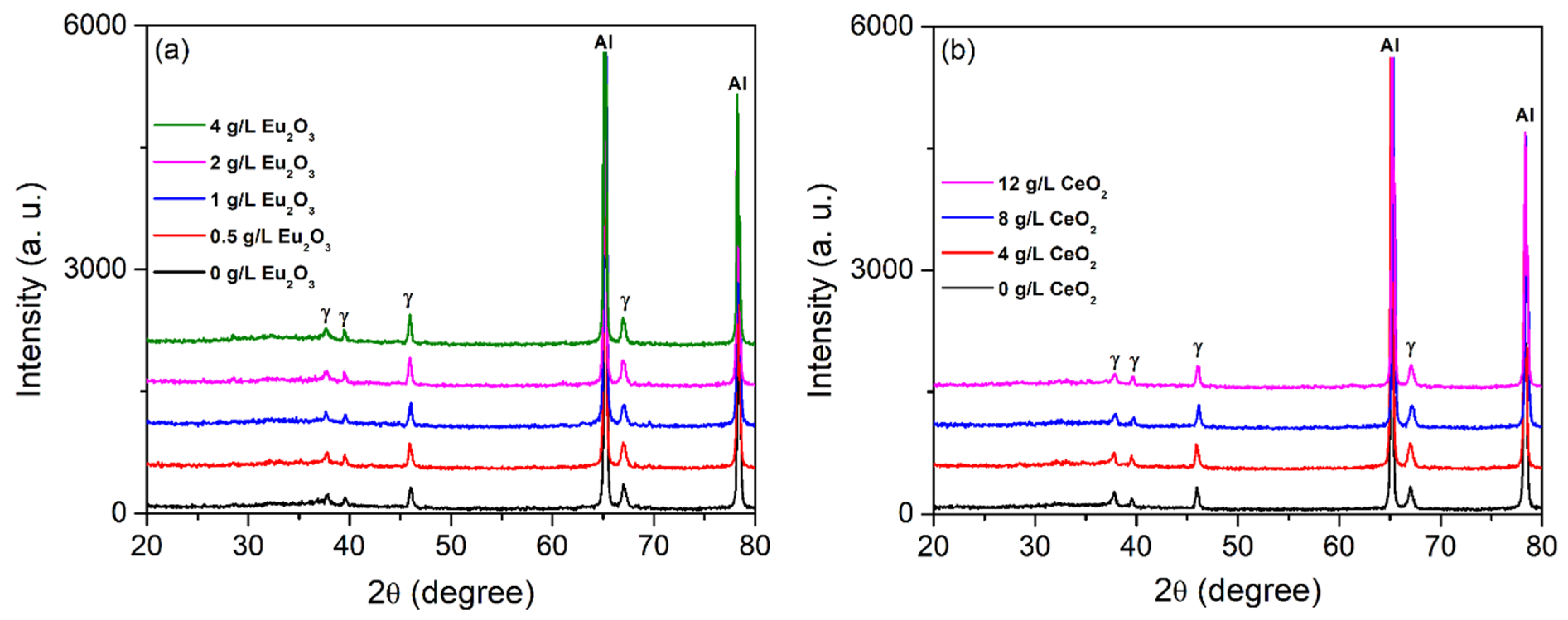
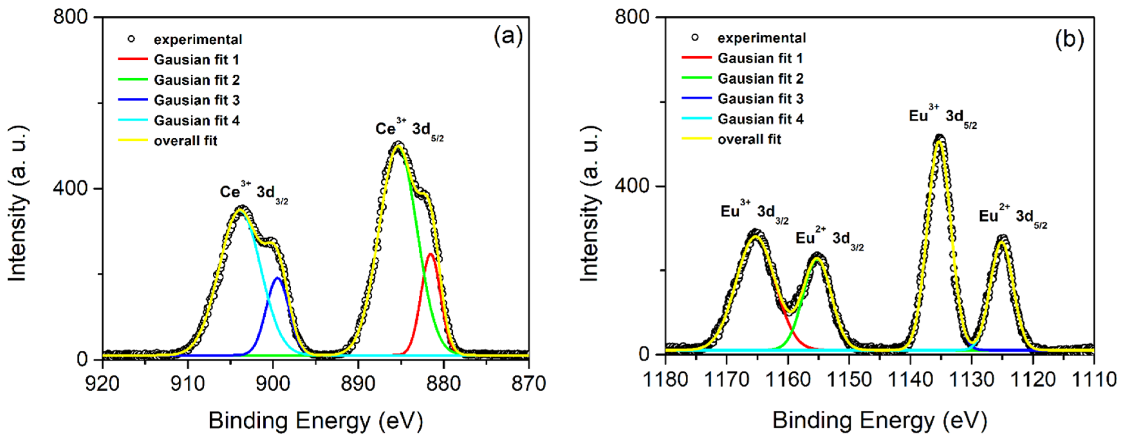
3.1. PEO Coatings’ Morphology, Phase and Chemical Composition

PEO is a high-voltage anodizing process of some metals (Al, Mg, Ta, Ti, etc.) and their alloys, combined with the plasma formation, as indicated by the presence of micro-discharges on the metal surface, and followed by the gas evolution [14]. High pressure (~102 MPa) and temperature (103 K to 104 K) at the micro-discharge sites induce numerous processes (electrochemical, thermodynamical, and plasma-chemical) responsible for structural, compositional, and morphological modifications of the obtained oxide coatings. The PEO formed oxide coatings usually have crystalline phases with constituents originating from both the electrolyte and the metal. During the PEO of aluminum, Al2O3 layer grows at the oxide/electrolyte and aluminum/oxide interfaces as a consequence of a strong electric field (~107 V/cm) induced relocation of O2−/OH and Al3+ ions across the oxide [15]. Moreover, melted aluminum and electrolyte components get drawn into the micro-discharge channels. From the channels, the oxidized aluminum gets ejected to the coating surface contacting the electrolyte. In that manner, the coating thickness increases around the channels. During the PEO, the electrophoretic effect drives CeO2 and Eu2O3 particles towards the anode. Local temperature at the micro-discharge sites is higher than the melting points of CeO2 and Eu2O3 particles (~2400 °C), enabling the molten particles to react with Al2O3 and form Ce and Eu ions doped Al2O3 coatings.
SEM images of coating surfaces, formed in supporting electrolyte by PEO, with the addition of CeO2 and Eu2O3 particles in various concentrations, are shown in Figure 1a. PEO coating displays a porous morphology with pores of varying diameter and shape, which appear at the sites of the micro-discharge channels because of the gas evolution erupting the molten oxide material during the PEO process [16]. The surface morphology of the formed coatings does not significantly change with the addition of CeO2 and Eu2O3 particles in supporting electrolyte. Elemental mapping by EDS shows that the main constituents of the coatings are uniformly distributed O, Ce, and Eu from the electrolyte and Al from the substrate (Figure 1b).
Integrated EDS analysis of all coatings created in the experiment is given in Table 1. The content of Ce and Eu in the coatings increases with increased concentration of CeO2 and Eu2O3 particles in supporting electrolyte, respectively.
XRD patterns of created coatings are presented in Figure 2. Diffraction peaks corresponding to the gamma phase of Al2O3 (reference ICCD card No. 10-0425) and Al substrate (reference ICCD card No. 89-4037) are observed in XRD patterns. Obviously, the formation of gamma Al2O3 during the PEO is favored by the rapid solidification of molten alumina due to the contact with surrounding low-temperature electrolyte [17]. We were not able to detect any peaks corresponding to CeO2 or Eu2O3 particles as well as any other Ce or Eu species, probably due to low concentration of incorporated Ce and Eu elements into Al2O3 coatings (Table 1).
For further investigation of the chemical nature and oxidation state of Ce and Eu in created coatings, we recorded a high-resolution Ce 3d and Eu 3d core-level spectra of Ce and Eu doped Al2O3 coating created in supporting electrolyte with the addition of 4 g/L CeO2 + 4 g/L Eu2O3 particles (Figure 3). The peak deconvolution of the high-resolution XPS peaks of Ce 3d shows that the level of Ce ion is composed of four Gaussian peaks, i.e., two pairs of doublets (3d5/2 at 881.5 eV and 885.3 eV, 3d3/2 at 899.5 eV and 903.9 eV), characteristic for Ce3+ oxidation state [18]. The Eu 3d core level spectrum consists of two doublets: (i) The Eu 3d5/2 (at 1135.3 eV) and Eu 3d3/2 (at 1165.3 eV) peaks, attributed to Eu3+ oxidation state, and (ii) at lower binding energies at ca. 1125.1 eV and 1155.2 eV, from the Eu2+ oxidation state [19]. These results indicate that interaction between CeO2 and Eu2O3 particles with Al2O3, under environmental conditions set by PEO, causes the reduction of Ce4+ ions to Ce3+ ions and the reduction of some of Eu3+ to Eu2+ ions in Al2O3 host (e.g., [10,11] and references therein).

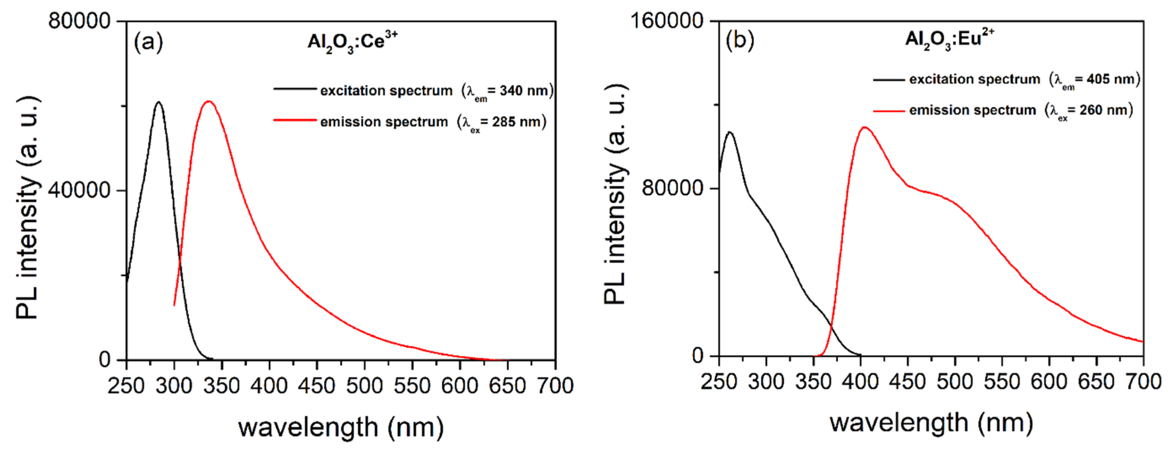
3.2. PL of Al2O3:Ce3+ and Al2O3:Eu2+ Coatings

The PL excitation and emission spectra of Ce3+ and Eu2+ singly doped Al2O3 coatings are presented in Figure 4. The PL excitation spectrum of Al2O3:Ce3+ coating (Figure 4a) exhibited the broad band in the range from 250 to 340 nm and peaked at about 285 nm, corresponding to the direct excitation from the Ce3+ ground state 4f to the field-splitting levels of 5d state [20]. The corresponding PL emission spectrum excited at 285 nm shows one broad emission band peaked at about 340 nm, attributed to the transitions of 5d excited state to the 2F7/2 and 2F5/2 ground states [20].
Figure 4b presents PL excitation and emission spectra of Al2O3 coating doped with Eu ions. The PL spectra show the characteristic Eu2+ broad band excitation and emission [21]. Although XPS indicates that Eu incorporated into Al2O3 is also in the 3+ oxidation state, typical f-f transitions of Eu3+ ions have not been identified in PL excitation and emission spectra, not even under the 395 nm excitation corresponding to the 7F05L6 transition of Eu3+. The PL excitation spectrum shows a large absorption band ranging from 250 to 330 nm, with center at 260 nm, attributed to the 4f65d1 multiplet excited states of Eu2+ ions. Under the excitation of 260 nm the PL emission spectrum shows two distinct bands reaching maxima at about 405 and 500 nm, caused by the 4f65d1→4f7 (8S7/2) transition of Eu2+ ions. This transition is structurally sensitive to the local environment around the Eu2+ in Al2O3 [21]. The gamma Al2O3 has two different sites for Al3+ ions. The appearance of two emission bands for a single transition of Eu2+ in Al2O3:Eu2+ is thus attributed to the Eu2+ substituting the Al3+ ions at both crystallographic sites.

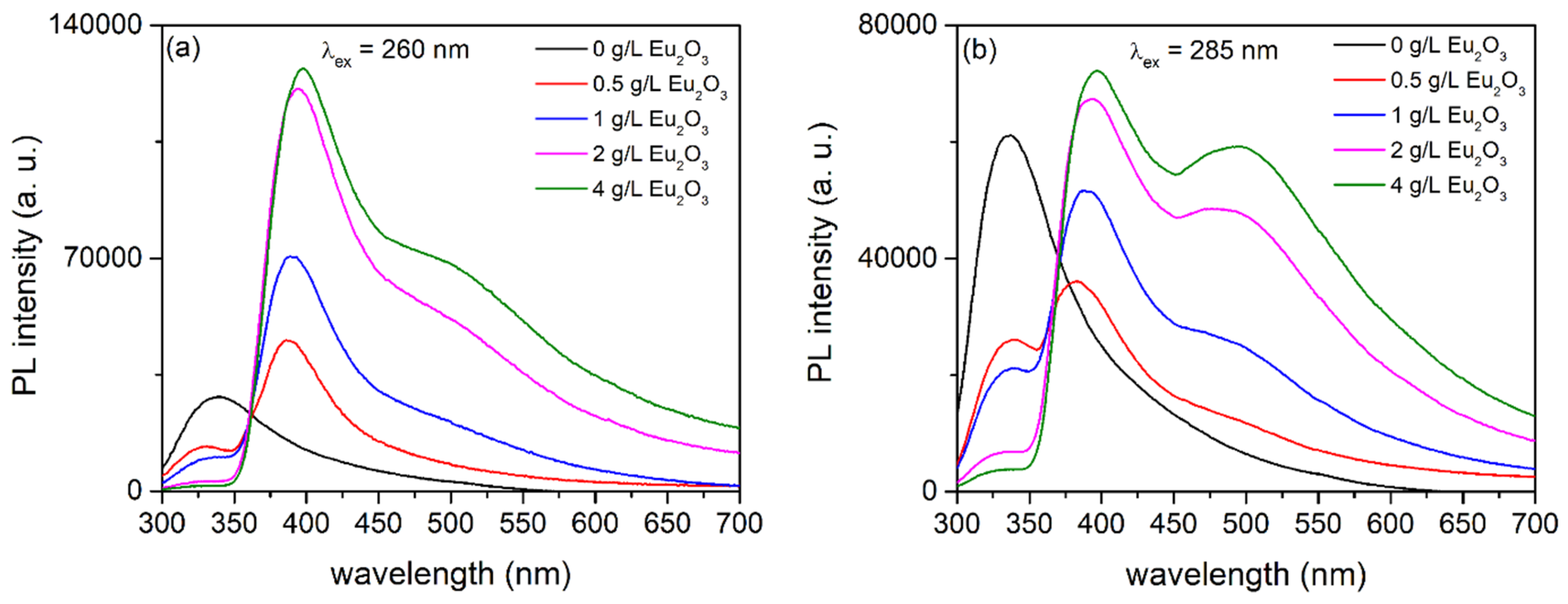
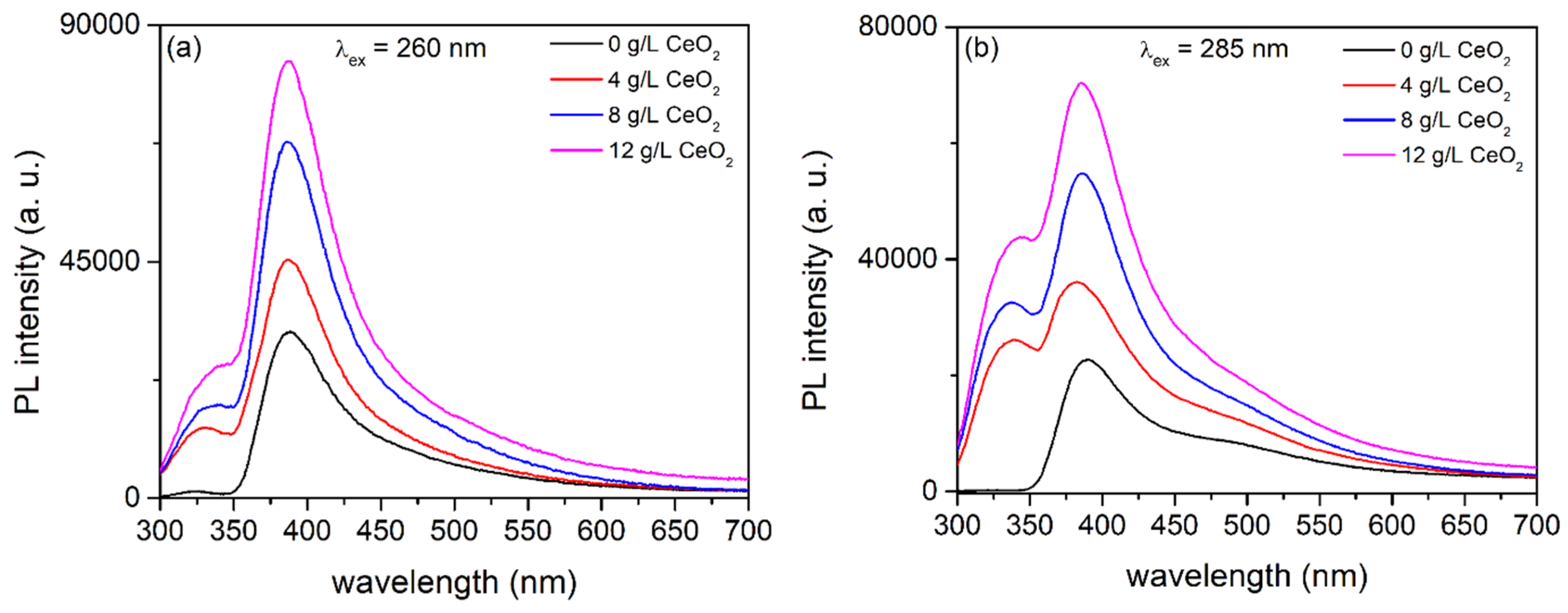
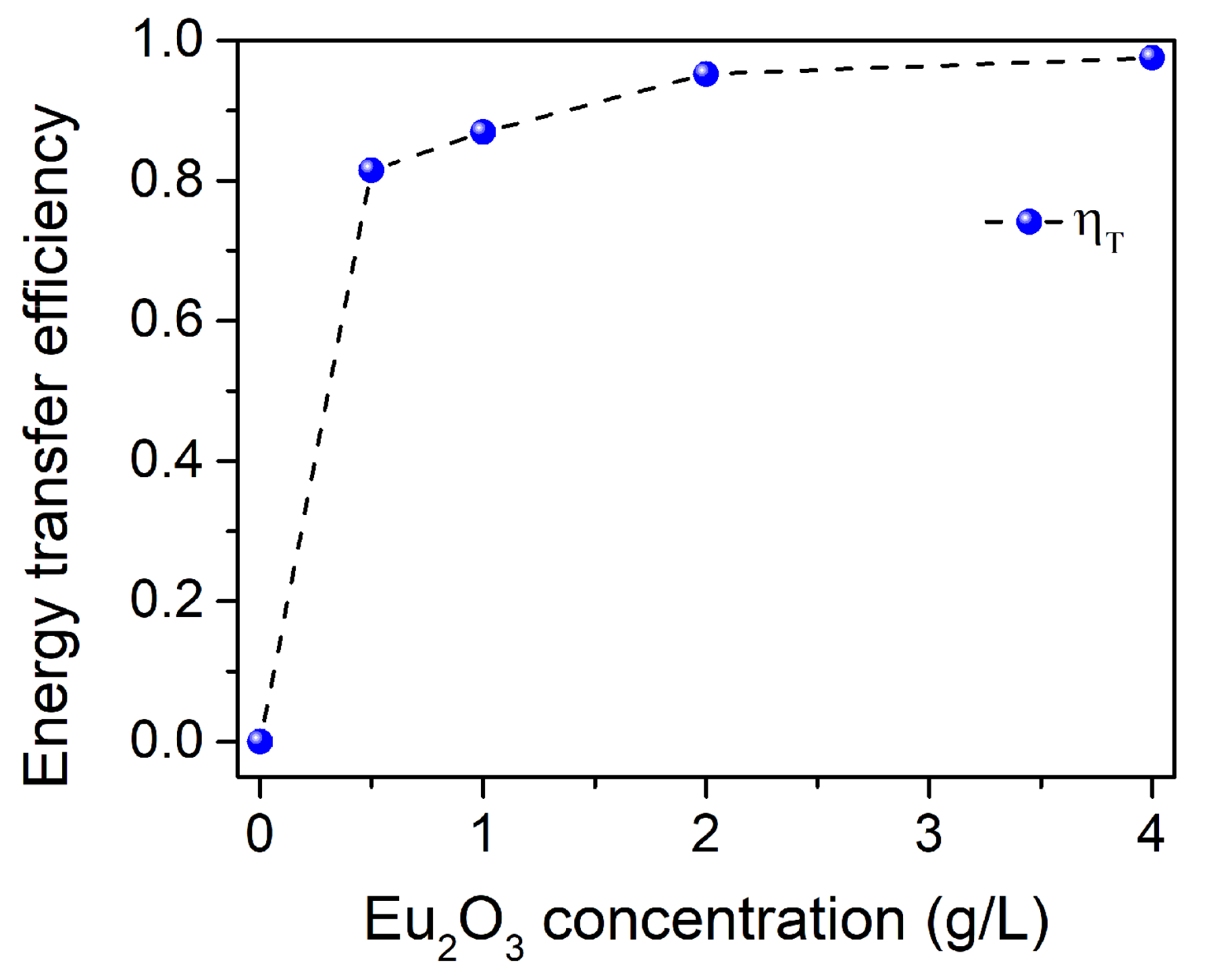
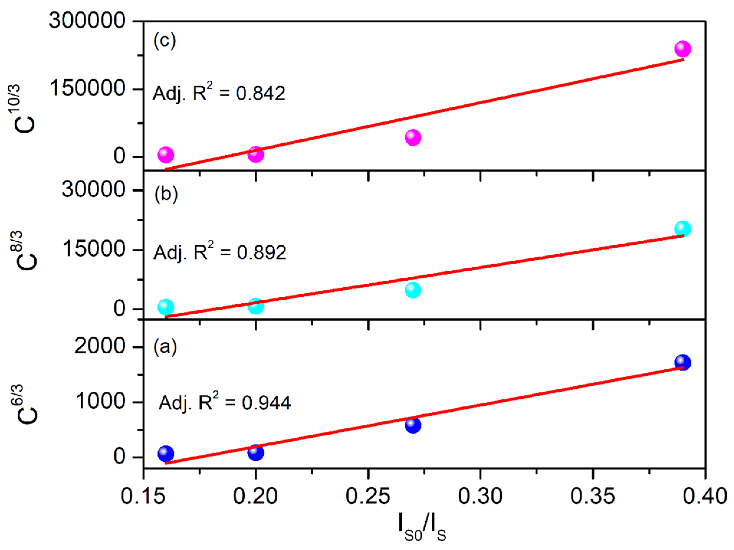
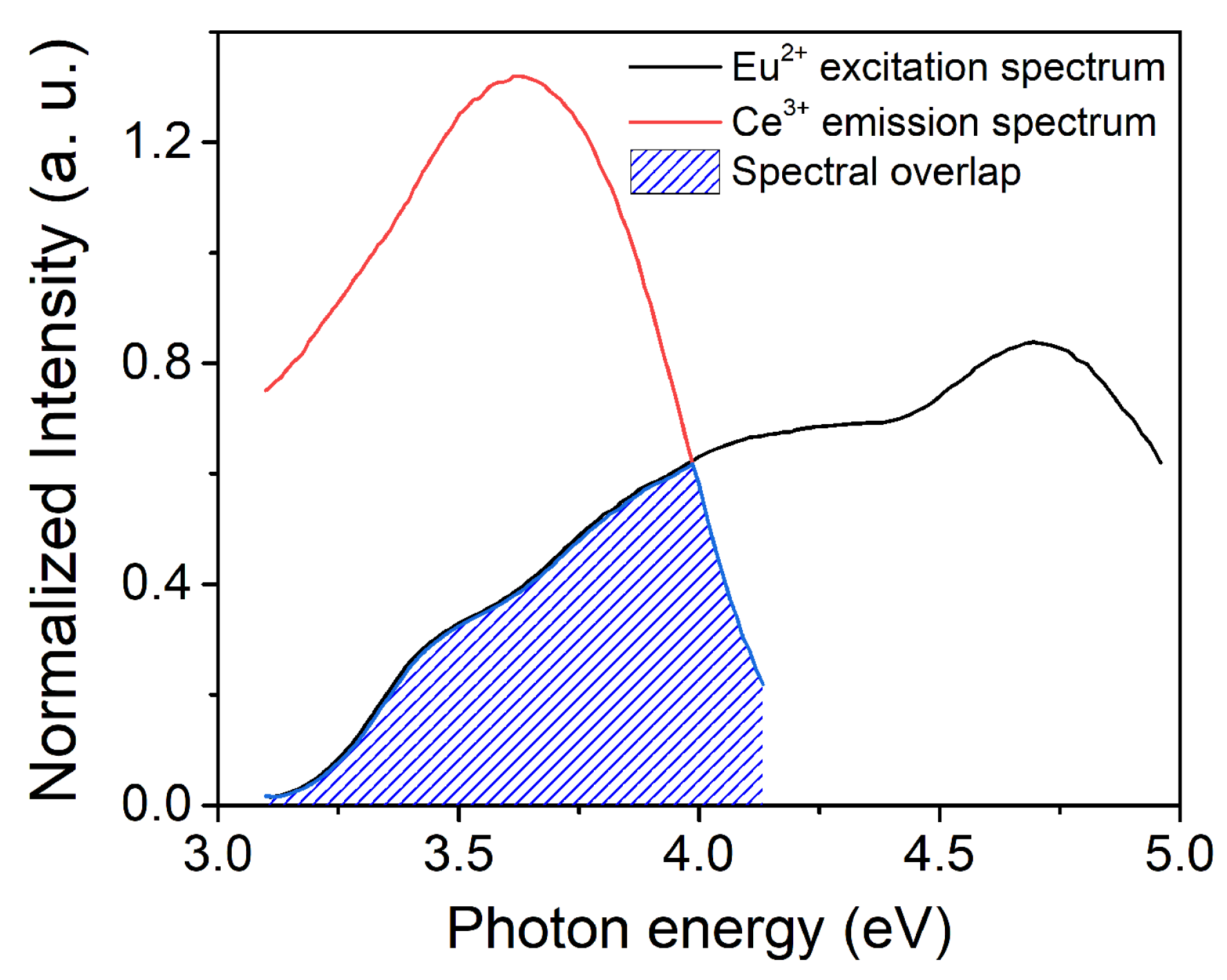
3.3. PL of Al2O3:Ce3+/Eu2+ Coatings

Figure 4 shows the spectral overlapping of the Ce3+ PL emission to the Eu2+ PL excitation in Al2O3 between 300 and 400 nm, which indicates that the energy transfer from a sensitizer Ce3+ to an activator Eu2+ is possible. To verify the energy transfer from Ce3+ to Eu2+ in Al2O3:Ce3+/Eu2+ coatings, the PL emission spectra excited at 260 and 285 nm of coatings formed in supporting electrolyte with the addition of 4 g/L CeO2 and different concentrations of Eu2O3 are shown in Figure 5. The PL emission spectra of Al2O3:Ce3+/Eu2+ coatings consist of the emission band peaking at about 345 nm, assigned to the 4f05d1→4f1 transition of Ce3+ ion, and two emission bands peaking at about 405 and 500 nm, attributed to the 4f65d→4f7 transition of Eu2+ ion. The intensity of the PL band of Ce3+ decreases with the increasing concentration of Eu2O3 in supporting electrolyte, i.e., content of incorporated Eu in Al2O3 coatings (Table 1), but the intensity of PL bands of Eu2+ increases. With the higher Eu2+ doping content, the Ce3+ emission practically disappears, and only the Eu2+ emission remains in the PL spectra of Al2O3:Ce3+/Eu2+ coatings. These results indicate that the energy transfer from Ce3+ to Eu2+ is confirmed. The intensity of PL bands of Eu2+ not only increases due to Ce3+→Eu2+ energy transfer, but also due to the increase of the Eu content in the Al2O3 coatings.
Ce3+→Eu2+ energy transfer in Al2O3:Ce3+/Eu2+ coatings created in supporting electrolyte with the addition of 0.5 g/L Eu2O3 and different concentrations of CeO2 is verified as well (Figure 6). The intensity of PL bands originating from Ce3+ and Eu2+ increases with increasing concentration of CeO2 in the supporting electrolyte, i.e., content of incorporated Ce3+ in Al2O3 coatings (Table 1). The intensity of PL bands of Eu2+ increases due to Ce3+→Eu2+ energy transfer, but the intensity of the PL band of Ce3+ increases due to the increase of the Ce3+ content in the Al2O3 coatings.
The energy transfer efficiency (ηT) from Ce3+ to Eu2+ can be calculated by the formula ηT = 1 – IS/IS0, where IS and IS0 are the PL intensities of the Ce3+ emissions with and without the presence of Eu2+, respectively [22]. The energy transfer efficiencies from Ce3+ to Eu2+ are calculated from the spectra in Figure 5 and presented in Figure 7. The energy transfer efficiency increases with increasing Eu2+ concentration, indicating that the energy transfer from Ce3+ to Eu2+ is effective under middle UV excitation. The energy transfer Ce3+→Eu2+ can also be observed via the shortening of the Ce3+ emission decay times with the increasing Eu2+ concentration, as demonstrated in Ref. [7].
In order to identify the energy transfer mechanism from a Ce3+ sensitizer to an Eu2+ activator, the equation of exchange interaction and electric multipolar interactions proposed by Dexter and Reisfeld was used [3]:
I S 0 I S C n 3 .
From Equation (1) the dominant multipolar interaction can be identified, where C is the total concentration of Ce3+ and Eu2+ ions, and n = 6, 8, 10 values correspond to dipole–dipole, dipole–quadropole and quadropole–quadropole interactions, respectively. In Figure 8, the plots of Cn/3 vs. IS0/IS are presented. The best fit is with n = 6, i.e., the energy transfer Ce3+→Eu2+ is primarily due to the electric dipole–dipole interaction.
The critical transfer distance for electric dipole–dipole interactions equal to [8]:
R C 6 [ ] = 6 · 10 3 L 4 · I ( C e ) · I ( E u ) d E I ( C e ) d E · I ( E u ) d E ,
where I(Ce) and I(Eu) are the intensities of Ce3+ emission and Eu2+ excitation spectra, respectively, and L is the largest energy point at which the spectral overlap occurs. As can be extracted from the graph in Figure 9, that point is equal to 3.985 eV, the term with integrals is equal to 0.3596 eV−1, and thus the critical distance was estimated to be 8.6 Å.

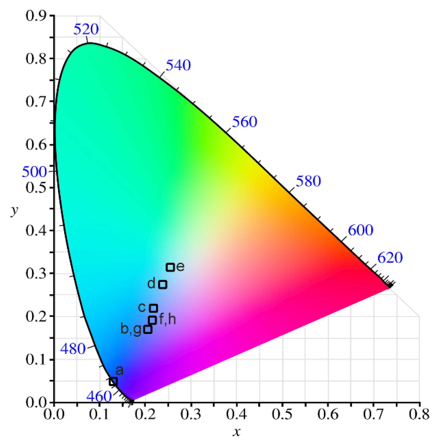
3.4. CIE Chromaticity Analysis

The Commission International de I’Eclairage (CIE) 1931 (x,y) coordinates of Al2O3:Ce3+/Eu2+ coatings created in supporting electrolyte with the addition different concentration of CeO2 and Eu2O3 were estimated by the JOES software, v. 2.8 [23], and the results are presented in Figure 10 and Table 2. From the diagram, the evident is the shift from pure blue towards the white color by increasing Eu2+ concentration. There is also a small shift in the same direction by changing the excitation from 260 to 285 nm. The emission color of the samples with constant Eu2+ is almost independent on the Ce3+ concentration. Thus, the emission color of Al2O3:Ce3+/Eu2+ can be fine-tuned from pure blue to white by increasing Eu2+ concentration.

4. Conclusions

In summary, we have successfully prepared Al2O3 coatings doped with Ce3+ and Eu2+ ions by the PEO process and their PL properties have been investigated in detail. PL emission spectra of Al2O3:Ce3+/Eu2+ are a sum of PL originating from 5d–4f transitions of Ce3+ and Eu2+ ions. Due to the spectral overlapping of the Ce3+ PL emission with the Eu2+ PL excitation in Al2O3, an energy transfer from Ce3+ sensitizer to Eu2+ activator occurs. The energy transfer mechanism is dominant by electric dipole–dipole interaction.

Author Contributions

S.S. conceptualized the idea; S.S. developed the coating; S.S. developed the methodology; S.S. and A.Ć. performed the experiments, and analyzed data; S.S. and A.Ć. contributed equally in manuscript preparation, editing and submission.

Funding

This research was funded by the Ministry of Education, Science and Technological Development of the Republic of Serbia under project No. 171035 and by the European Union Horizon 2020 research and innovation program under the Marie Sklodowska-Curie grant agreement No. 823942.

Conflicts of Interest

The authors declare no conflict of interest.

References

  1. Li, G.G.; Tian, Y.; Zhao, Y.; Lin, J. Recent progress in luminescence tuning of Ce3+ and Eu2+-activated phosphors for pc- WLEDs. Chem. Soc. Rev. 2015, 44, 8688–8713. [Google Scholar] [CrossRef] [PubMed]
  2. Yan, S. On the origin of temperature dependence of the emission maxima of Eu2+ and Ce3+- activated phosphors. Opt. Mater. 2018, 79, 172–185. [Google Scholar] [CrossRef]
  3. Li, K.; Shang, M.; Lian, H.; Lin, J. Recent development in phosphors with different emitting colors via energy transfer. J. Mater. Chem. C 2016, 4, 5507–5530. [Google Scholar] [CrossRef]
  4. Martín-Cano, D.; Martín-Moreno, L.; García-Vidal, F.J.; Moreno, E. Resonance Energy Transfer and Superradiance Mediated by Plasmonic Nanowaveguides. Nano Lett. 2010, 10, 3129–3134. [Google Scholar] [CrossRef]
  5. Caligiuri, V.; Palei, M.; Imran, M.; Manna, L.; Krahne, R. Planar Double-Epsilon-Near-Zero Cavities for Spontaneous Emission and Purcell Effect Enhancement. ACS Photonics 2018, 5, 2287–2294. [Google Scholar] [CrossRef]
  6. Zhao, J.; Sun, X.; Wang, Z. Ce3+/Eu2+ doped SrSc2O4 phosphors: Synthesis, luminescence and energy transfer from Ce3+ to Eu2+. Chem. Phys. Lett. 2018, 691, 68–72. [Google Scholar] [CrossRef]
  7. Hu, Z.; Cheng, Z.; Dong, P.; Zhang, H.; Zhang, Y. Enhanced photoluminescence property of single-component CaAlSiN3:Ce3+, Eu2+ multicolor phosphor through Ce3+-Eu2+ energy transfer. J. Alloys Compd. 2017, 727, 633–641. [Google Scholar] [CrossRef]
  8. Yan, J.; Liu, C.; Zhou, W.; Huang, Y.; Tao, Y.; Liang, H. VUV-UV–vis photoluminescence of Ce3+ and Ce3+-Eu2+ energy transfer in Ba2MgSi2O7. J. Lumin. 2017, 185, 251–257. [Google Scholar] [CrossRef]
  9. Li, C.; Zheng, H.; Wei, H.; Qiu, S.; Xu, L.; Wang, X.; Jiao, H. A color tunable and white light emitting Ca2Si5N8:Ce3+, Eu2+ phosphor via efficient energy transfer for near-UV white LEDs. Dalton Trans. 2018, 47, 6860–6867. [Google Scholar] [CrossRef]
  10. Stojadinović, S.; Vasilić, R. Eu2+ photoluminescence in Al2O3 coatings obtained by plasma electrolytic oxidation. J. Lumin. 2018, 199, 240–244. [Google Scholar] [CrossRef]
  11. Stojadinović, S.; Vasilić, R. Photoluminescence of Ce3+ and Ce3+/Tb3+ ions in Al2O3 host formed by plasma electrolytic oxidation. J. Lumin. 2018, 203, 576–581. [Google Scholar] [CrossRef]
  12. Kim, D.-J. Lattice Parameters, Ionic Conductivities, and Solubility Limits in Fluorite-Structure MO2 Oxide [M = Hf4+, Zr4+, Ce4+, Th4+, U4+] Solid Solutions. J. Am. Ceram. Soc. 1989, 72, 1415–1421. [Google Scholar] [CrossRef]
  13. Xie, H.; Lu, J.; Guan, Y.; Huang, Y.; Wei, D.; Seo, H.J. Abnormal Reduction, Eu3+ → Eu2+, and Defect Centers in Eu3+ -Doped Pollucite, CsAlSi2O6, Prepared in an Oxidizing Atmosphere. Inorg. Chem. 2014, 53, 827–834. [Google Scholar] [CrossRef] [PubMed]
  14. Stojadinović, S.; Vasilić, R.; Perić, M. Investigation of plasma electrolytic oxidation on valve metals by means of molecular spectroscopy–a review. RSC Adv. 2014, 4, 25759–25789. [Google Scholar] [CrossRef]
  15. Snizhko, L.O.; Yerokhin, A.L.; Pilkington, A.; Gurevina, N.L.; Misnyankin, D.O.; Leyland, A.; Matthews, A. Anodic processes in plasma electrolytic oxidation of aluminium in alkaline solutions. Electrochim. Acta 2004, 49, 2085–2095. [Google Scholar] [CrossRef]
  16. Yerokhin, A.L.; Nie, X.; Leyland, A.; Matthews, A.; Dowey, S.J. Plasma electrolysis for surface engineering. Surf. Coat. Technol. 1999, 122, 73–93. [Google Scholar] [CrossRef]
  17. McPherson, R. Formation of metastable phases in flame and plasma-prepared alumina. J. Mater. Sci. 1973, 8, 851–858. [Google Scholar] [CrossRef]
  18. Yagoub, M.Y.A.; Swart, H.C.; Noto, L.L.; Bergman, P.; Coetsee, E. Surface characterization and photoluminescence properties of Ce3+,Eu co-doped SrF2 nanophosphor. Materials 2015, 8, 2361–2375. [Google Scholar] [CrossRef] [Green Version]
  19. Rogers, J.J.; MacKenzie, K.J.D.; Rees, G.; Hanna, J.V. New phosphors based on the reduction of Eu(III) to Eu(II) in ion-exchanged aluminosilicate and gallium silicate inorganic polymers. Ceram. Int. 2018, 44, 1110–1119. [Google Scholar] [CrossRef]
  20. Wang, F.; Wang, W.; Zhang, L.; Zheng, J.; Jin, Y.; Zhang, J. Luminescence properties and its red shift of blue emitting phosphor Na3YSi3O9:Ce3+ for UV LED. RSC Adv. 2017, 7, 27422–27430. [Google Scholar] [CrossRef] [Green Version]
  21. Yang, Y.; Wei, H.; Zhang, L.; Kisslinger, K.; Melcher, C.L.; Wu, Y. Blue emission of Eu2+-doped translucent alumina. J. Lumin. 2015, 168, 297–303. [Google Scholar] [CrossRef] [Green Version]
  22. Chen, H.; Li, C.; Hua, Y.; Yu, L.; Jiang, Q.; Deng, D.; Zhao, S.; Ma, H.; Xu, S. Influence of energy transfer from Ce3+ to Eu2+ on luminescence properties of Ba3Si6O9N4:Ce3+,Eu2+ phosphors. Ceram. Int. 2014, 40, 1979–1983. [Google Scholar] [CrossRef]
  23. Ćirić, A.; Stojadinović, S.; Sekulić, M.; Dramićanin, M.D. JOES: An application software for Judd-Ofelt analysis from Eu3+ emission spectra. J. Lumin. 2019, 205, 351–356. [Google Scholar] [CrossRef]
Figure 1. (a) SEM images of coatings created in supporting electrolyte: (i) Without addition CeO2 and Eu2O3 and with the addition of (ii) 4 g/L CeO2, (iii) 4 g/L Eu2O3, (iv) 4 g/L CeO2 + 4 g/L Eu2O3. (b) Energy-dispersive x-ray spectroscopy (EDS) maps of coating created in supporting electrolyte with the addition of 4 g/L CeO2 + 4 g/L Eu2O3.
Coatings 09 00819 g001
Figure 2. (a) XRD patterns of coatings created in 0.1 M H3BO3 + 0.05 M Na2B4O7 + 4 g/L CeO2 with the addition Eu2O3 in different concentrations, (b) XRD patterns of coatings formed in 0.1 M H3BO3 + 0.05 M Na2B4O7 + 0.5 g/L Eu2O3 with the addition CeO2 in different concentrations.
Coatings 09 00819 g002
Figure 3. (a) High-resolution XPS spectrum of Ce 3d, (b) high-resolution Eu 3d XPS spectrum of coating created with the addition of 4 g/L CeO2 + 4 g/L Eu2O3 to the supporting electrolyte.
Coatings 09 00819 g003
Figure 4. Photoluminescence (PL) excitation and emission spectra of: (a) Al2O3:Ce3+, (b) Al2O3:Eu2+, created in supporting electrolyte with the addition of 4 g/L CeO2 and 4 g/L Eu2O3, respectively.
Coatings 09 00819 g004
Figure 5. PL emission spectra of Al2O3:Ce3+/Eu2+ coatings formed in supporting electrolyte with the addition of 4 g/L CeO2 and different concentrations of Eu2O3 excited at: (a) 260 nm, (b) 285 nm.
Coatings 09 00819 g005
Figure 6. PL emission spectra of Al2O3:Ce3+/Eu2+ coatings formed in supporting electrolyte with the addition of 0.5 g/L Eu2O3 and different concentrations of CeO2 excited at: (a) 260 nm, (b) 285 nm.
Coatings 09 00819 g006
Figure 7. Energy transfer efficiency of Al2O3:Ce3+/Eu2+ coatings created in supporting electrolyte with the addition of 4 g/L CeO2 and different concentrations of Eu2O3.
Coatings 09 00819 g007
Figure 8. Plot of Cn/3 vs. IS0/IS for: (a) n = 6, (b) n = 8, (c) n = 10.
Coatings 09 00819 g008
Figure 9. Normalized spectral line-shapes for the Ce3+ emission and Eu2+ excitation.
Coatings 09 00819 g009
Figure 10. Commission International de I’Eclairage (CIE) 1931 chromaticity diagram of Al2O3:Ce3+/Eu2+ coatings doped with various concentrations of CeO2 and Eu2O3 particles and excited at 260 nm. Labels are explained in Table 2.
Coatings 09 00819 g010
Table 1. EDS analysis of plasma electrolytic oxidation (PEO) coatings coalesced in supporting electrolyte with different concentrations of added CeO2 and Eu2O3 powders.
Concentration of Particles in Supporting ElectrolyteAtomic (%)
OAlCeEu
4 g/L CeO265.2534.620.13-
4 g/L Eu2O265.1934.55-0.26
4 g/L CeO2 + 0.5 g/L Eu2O364.8934.950.100.06
4 g/L CeO2 + 1 g/L Eu2O364.7335.060.110.09
4 g/L CeO2 + 2 g/L Eu2O364.3935.350.110.16
4 g/L CeO2 + 4 g/L Eu2O364.7934.820.120.27
0 g/L CeO2 + 0.5 g/L Eu2O364.9534.98-0.07
4 g/L CeO2 + 0.5 g/L Eu2O364.9034.940.100.06
8 g/L CeO2 + 0.5 g/L Eu2O364.9934.730.210.07
12 g/L CeO2 + 0.5 g/L Eu2O364.9734.650.320.06
Table 2. CIE x, y coordinates, color purity and dominant wavelength of Al2O3:Ce3+/Eu2+, coatings doped with various concentrations of CeO2 and Eu2O3 particles and excited at 260 and 285 nm.
LabelConcentration of Particlesλex
(nm)
xyColor Purityλdominant
(nm)
CeO2Eu2O3
a402600.106440.086031467
b40.52600.209440.180670.606957471
c412600.212950.214470.501821477
d422600.240270.252170.374879483
e442600.256930.276660.285429488
f00.52600.215030.192080.550572472
g80.52600.20220.177730.606957471
h120.52600.217430.193860.550572472

