Article

Simple Non-Destructive Method of Ultrathin Film Material Properties and Generated Internal Stress Determination Using Microcantilevers Immersed in Air

1
School of Sciences, Harbin Institute of Technology, Shenzhen, Shenzhen 518055, China
2
Institute of Physics, Czech Academy of Sciences, 18221 Prague, Czech Republic
3
Drážní revize s.r.o., Místecká 1120/103, 70300 Ostrava–Vitkovice, Czech Republic
*
Author to whom correspondence should be addressed.
Coatings 2019, 9(8), 486; https://doi.org/10.3390/coatings9080486
Submission received: 5 June 2019 / Revised: 22 July 2019 / Accepted: 27 July 2019 / Published: 1 August 2019

Abstract

:
Recent progress in nanotechnology has enabled to design the advanced functional micro-/nanostructures utilizing the unique properties of ultrathin films. To ensure these structures can reach the expected functionality, it is necessary to know the density, generated internal stress and the material properties of prepared films. Since these films have thicknesses of several tens of nm, their material properties, including density, significantly deviate from the known bulk values. As such, determination of ultrathin film material properties requires usage of highly sophisticated devices that are often expensive, difficult to operate, and time consuming. Here, we demonstrate the extraordinary capability of a microcantilever commonly used in a conventional atomic force microscope to simultaneously measure multiple material properties and internal stress of ultrathin films. This procedure is based on detecting changes in the static deflection, flexural and torsional resonant frequencies, and the corresponding quality factors of the microcantilever vibrating in air before and after film deposition. In contrast to a microcantilever in vacuum, where the quality factor depends on the combination of multiple different mechanical energy losses, in air the quality factor is dominated just by known air damping, which can be precisely controlled by changing the air pressure. Easily accessible expressions required to calculate the ultrathin film density, the Poisson’s ratio, and the Young’s and shear moduli from measured changes in the microcantilever resonant frequencies, and quality factors are derived. We also show that the impact of uncertainties on determined material properties is only minor. The validity and potential of the present procedure in material testing is demonstrated by (i) extracting the Young’s modulus of atomic-layer-deposited TiO2 films coated on a SU-8 microcantilever from observed changes in frequency response and without requirement of knowing the film density, and (ii) comparing the shear modulus and density of Si3N4 films coated on the silicon microcantilever obtained numerically and by present method.

1. Introduction

Functional micro-/nanostructures made of substrate and one or multiple ultrathin films are widely used in applications like photovoltaics [1], micro-electronics [2], optics [3,4], tunable resonators [5,6], and various sensors [7,8,9,10,11,12]. Preparation of these structures involves repeated usage of multiple fabrication processes such as deposition, lithography, etching, and cleaning. In order to prevent the mechanical failure or to guarantee that the structures would reach the desired operating conditions, the material properties of prepared ultrathin films must be known. During film deposition the internal stress that often originates from a coefficient of thermal expansion mismatch can be generated [13]. For films of thicknesses ranging from hundreds of nm to about tens of μm, the nanoindentation [14], bulge test [15], and the resonant methods [16] are the most common techniques used to determine the film material properties. Noticing that for micro-sized samples the density is estimated based on the known bulk values. However, once film thickness shrinks from micro- to nanoscale (i.e., tens of nm), the density of particularly polymer, organic, composite, or porous films can start to deviate from the bulk values (e.g., changes in deposition parameters affect notably prepared film density) [17,18]. In addition, usage of different film preparation processes can also cause significant variations in the material properties and density of designed nanostructure. As a result, current procedures of ultrathin film material properties determination require either simultaneous measurements on multiple sophisticated devices [19,20,21] or the specially designed micro-/nanomechanical resonators or experimental setup with the advanced computational tools [22,23,24,25,26]. For instance, the high-resolution transmission electron microscope is used to precisely control the force loading/unloading during the nanoindentation of a nanoscale sample [20,21]. Drawbacks of these procedures are that combined measurements on either several sophisticated devices or one specially-designed device are difficult to perform, time consuming, often expensive, and each developed procedure is usually limited to only a specific class of materials. The resonant methods can be also integrated in situ into the nanomaterial deposition systems [27,28].
In response, here we demonstrate the outstanding capability of common microcantilever to determine the density, generated internal stress, the Poisson’s ratio, and the elastic properties of solid and polymer ultrathin films, from measured static and dynamic responses of the microcantilever, before and after depositing a thin layer film on its surface. Sketch of the microcantilever with the deposited film is given in Figure 1. We emphasize here that the present procedure utilizes, in addition to well-established measurements of the cantilever static deflection, the flexural and torsional resonant frequencies of the cantilever operating in air; also monitoring often neglected changes in the corresponding quality factors (Q-factors). As a direct consequence, no additional experimental setup or specially designed microcantilevers are required, enabling non-destructive and easily accessible material characterization and testing of ultrathin films. Noticing that Q-factor is a dimensionless parameter describing the efficiency of the designed resonator (i.e., higher Q-factor values stand for lower dissipation and higher efficiency). Importantly, in air the Q-factor is proportional to the material properties and dimensions of the designed microcantilever, and a known air damping that can be precisely controlled by changing the air pressure [29]. Other energy losses, such as the support, surface or the thermo-elastic loss, have only a negligibly small impact on the Q-factor of microcantilever submerged in air. When film is sputtered on the resonator surface, it alters the material properties and dimensions of the microcantilever resonator, yielding changes in Q-factor. As such, Q-factor provides an additional source of information on prepared ultrathin film(s).
We first derive easily accessible expressions needed to calculate the material properties of an ultrathin film from observed changes in flexural and torsional resonant frequencies and Q-factors of the microcantilever operating in air. Then, we analyze the sensitivity of calculated material properties of ultrathin film on uncertainties in frequency (Q-factor) and dimensions measurements and, afterwards, we validate our theoretical findings by comparing theoretical predictions with experimental results and numerical computations. Despite the fact that analysis is carried out on rectangular microcantilevers, the obtained results and developed procedure of thin film material characterization are valid for other cantilever shapes. In this case, just the flexural and torsional rigidities and hydrodynamic functions used in the model must be recalculated.

2. Theory

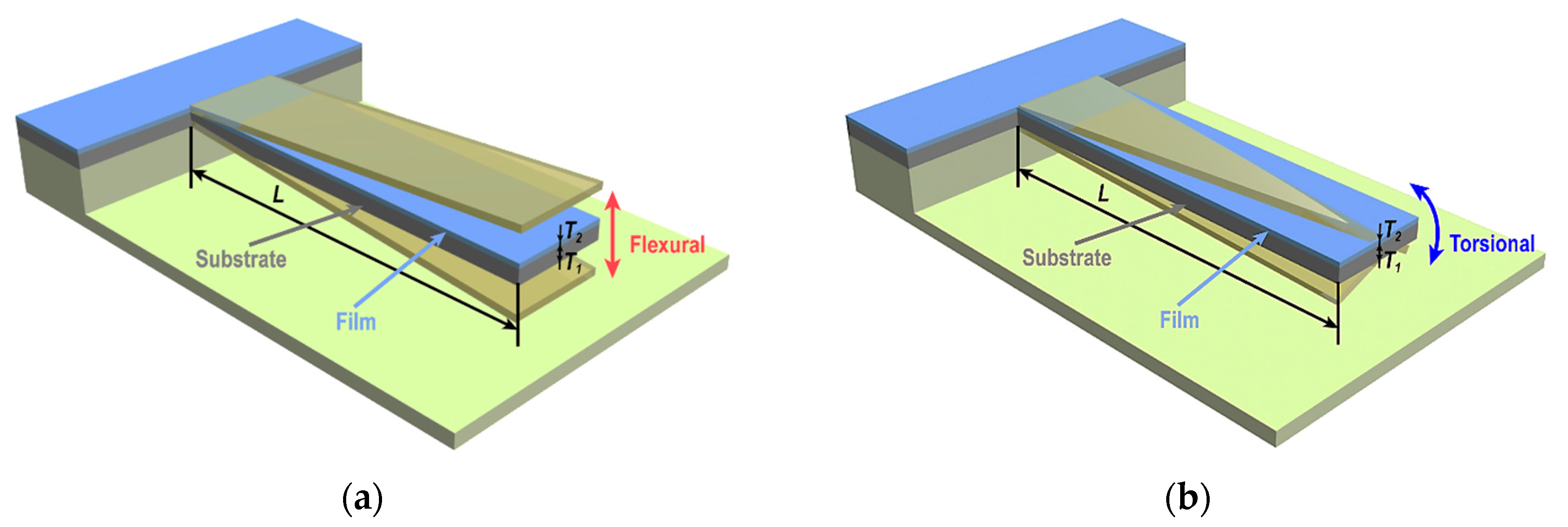
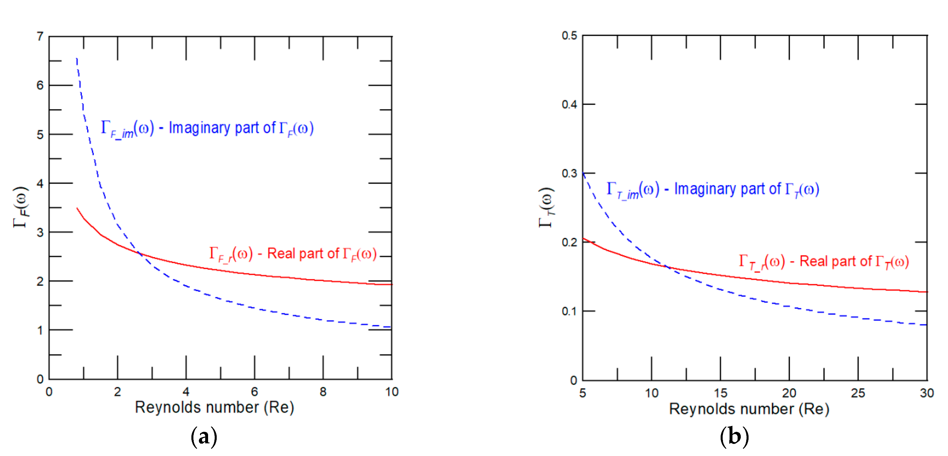
2.1. Flexural Oscillations of Two-Layered (Multi-Layered) Microcantilever Operating in Air

To begin, we recall a known fact that once a thin layer film is sputtered on an elastic substrate, it generates in-plane stresses and also alters the overall cantilever resonator elastic properties, particularly in near vicinity of its clamped end [6,30,31,32,33]. These effects, that originate from mismatches in strains and the coefficient of thermal expansion between substrate and film, have been proven to notably affect the resonant frequencies of ultrathin cantilever resonators (i.e., thin sheets) [32,33]. Nevertheless, for relatively thick microcantilevers (e.g., ultrathin film sputtered on a thick elastic substrate), of which are considered in the present work, the cantilever free end allows the generated internal stress to be relaxed [31]. Hence, for out-plane flexural vibrational modes, the governing equation for the dynamic deflection function u(x,t) of the microcantilever consisting of substrate and coated film (see Figure 1a) is given by
( ρ 1 S 1 + ρ 2 S 2 ) 2 u ( x , t ) t 2 + D F 4 u ( x , t ) x 4 = F drive ( x , t ) + F hydro ( x , t ) ,
where D F =   1 12 E 1 W T 1 3 r ( ξ F , η ) ; subscript 1 and 2 stand for substrate and film, respectively; ρ, S, W, T are the density, cross sectional area, width, and thickness, respectively; r(ξF,η) = [ξF2η4 + 4ξFη(1 + 1.5η + η2) + 1]/(1 + ξFη), ξF = E2/E1, η = T2/T1, F drive ( x , t ) is the external driving force per unit length of an arbitrary form that set the microcantilever into motion; F hydro ( x , t )   is the hydrodynamic force of surrounding air.
It shall be pointed out that detailed theoretical analysis of a homogeneous microcantilever (i.e., made of one material layer) performing flexural oscillations in air can be found in [34,35]. In present work, we extend these theoretical results to account for two material layers required to characterize the material properties of ultrathin films. Moreover, our results can be also directly applied to the microcantilever consisting of N material layers just by recalculating linear density, ρS (where ρ can be viewed as the effective density and S is the cantilever cross-sectional area), and flexural rigidity using the following general relationships:
ρ S = i = 1 N ρ i S i , D F = i = 1 N E i i u * 2 d S ( i = 1 N E i i u * d S ) 2 i = 1 N E i S i ,
where u* is the local coordinate in the lateral direction, i is the i-th region of cantilever beam cross section [36].
The general form of the hydrodynamic force obtained by solving the Fourier-transformed continuity and Navier–Stokes equations (i.e., computations are in the time domain Fourier-transform), for an incompressible fluid as F hydro ( x | ω ) = κ F ρ air ω 2 W 2 Γ F ( ω ) U ( x | ω ) , where U ( x | ω ) is the Fourier-transformed deflection function, κ F = π 4 , ρair is the air density, and Γ F ( ω ) is the hydrodynamic function for flexural vibration mode. Then, taking the Fourier transform of Equation (1) and rearranging terms yields:
d 4 U ( x | ω ) d x 4 ( γ ( n ) 2 ω ω v F ( n ) ) 2 [ 1 + κ F ρ air W ρ 1 T 1 ( 1 + μ η ) Γ F ( ω ) ] U ( x | ω ) = F ˜ drive ( x | ω ) ,
where μ = ρ 2 / ρ 1 , F ˜ drive ( x | ω ) = F drive ( x | ω ) L 4 / D F , ω v F ( n ) = ( γ ( n ) L ) 2 D F / [ ρ 1 T 1 ( 1 + μ η ) ] is the cantilever angular resonant frequency in vacuum of the n-th vibrational mode, n = 1, 2, 3, … stands for the considered vibrational mode, L is the cantilever length, ω is a characteristic angular frequency of the microcantilever oscillations and γ ( n ) is obtained as the positive root(s) of the following characteristic transcendental equation:
cosh γ   cos γ + 1 = 0 .
For an arbitrary form of the driving force the general solution of Equation (3) can be found by the eigenfunction expansion method. In this case, the dynamic deflection function can be obtained as a linear combination of the microcantilever mode shapes, θ F ( n ) ( x ) = sin h ( γ ( n ) x ) sin ( γ ( n ) x ) [ sin h ( γ ( n ) ) + sin ( γ ( n ) ) cos h ( γ ( n ) ) + cos ( γ ( n ) ) ] × [ cos h ( γ ( n ) x ) cos ( γ ( n ) x ) ] (see [37]) and the one reads:
U ( x | ω ) = n = 1 B F ( n ) ( ω ) θ F ( n ) ( x ) ,
where B F ( n ) ( ω ) is found using the orthonormal properties of θ F ( n ) ( x ) as
B F ( n ) ( ω ) = 0 L F ˜ dr ( x ¯ | ω ) θ F ( n ) ( x ¯ ) d x ¯ γ ( n ) 4 ( γ ( n ) 2 ω ω v F ( n ) ) 2 [ 1 + κ F ρ air W ρ 1 T 1 ( 1 + μ η ) Γ F ( ω ) ] .
The dissipative effect of air is small compared to viscous fluid (i.e., Q(n) >> 1 [34,35,38]); therefore, in a vicinity of the resonance peaks Γ F ( ω ) Γ F _ r ( ω ) + i Γ F _ i m ( ω ) , where Γ F _ r ( ω ) and Γ F _ i m ( ω ) are the real and imaginary components of the dimensionless hydrodynamic function for cantilever performing flexural oscillations. Then, the resonant frequency and Q-factor of n-th microcantilever vibrational mode in air can be obtained with an analogy to a simple harmonic oscillator as:
ω F ( n ) = ω v F ( n ) 1 + κ F ρ air W ρ 1 T 1 ( 1 + μ η ) Γ F _ r ( ω F ( n ) ) ,
Q F ( n ) = ρ 1 T 1 ( 1 + μ η ) κ F ρ air W + Γ F _ r ( ω F ( n ) ) Γ F _ i m ( ω F ( n ) ) .
For reader’s convenience, we present dependencies of the real Γ F _ r ( ω F ( 1 ) ) and imaginary Γ F _ i m ( ω F ( 1 ) ) components of the hydrodynamic function on the fundamental mode frequency represented through the Reynolds number, Re = π 4 ω W 2 ρ air / μ air , where μ air is the viscosity of air, in Figure 2a. Noticing only that the Reynolds number is a dimensionless parameter used to predict the flow pattern. For a microcantilever consisting of N material layers, the normalized “effective” density ρ 1 T 1 ( 1 + μ η ) in Equations (7) and (8) is replaced by i = 1 N ρ i T i . Furthermore, for higher vibrational modes the hydrodynamic function depends on the following two dimensionless parameters: (i) The Reynolds number defined now as Re = ω W 2 ρ air / μ air ; and (ii) the normalized mode shape given by κ = γ ( n ) W / L [39]. The exact form of the hydrodynamic function for an arbitrary mode number can be found in [39,40]. The general solution for the dynamic deflection has been obtained using the eigenfunction expansion method (see structure of Equation (5)); therefore, the obtained expressions for the resonant frequency and Q-factor represented by Equations (7) and (8) are valid for an arbitrary vibrational mode (i.e., for higher modes only the hydrodynamic function must be recalculated).

2.2. Torsional Oscillations of Two-Layered (Multi-Layered) Microcantilever Operating in Air
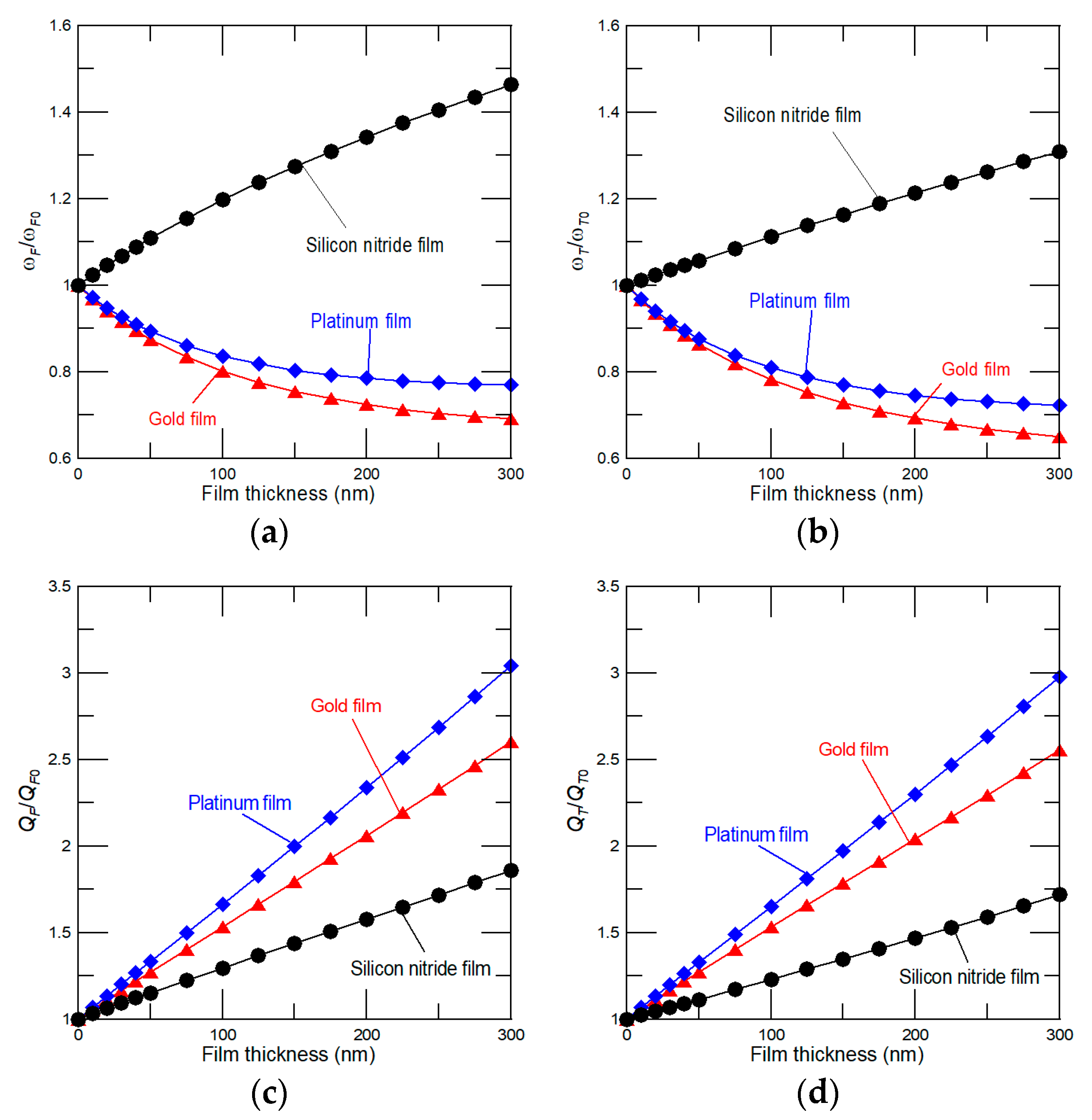
The resonant frequency and Q-factor of a two(multi)-layered microcantilever vibrating in air can be obtained in the same way as done in the previous section for flexural oscillations. Briefly, by accounting for the membrane analogy proposed by Prandtl in 1903, similarities with the theoretical model for flexural oscillations of a multilayered beam in vacuum given in Zapomel et al. [36] and theory of Green and Sader [41], the general governing equation and boundary conditions for torsional oscillations of a two-layered microcantilever (see Figure 1b) operating in air takes the following form:
D T r 2 ϕ ( x , t ) x 2 ρ 1 W 3 T 1 12 [ 1 + ε 1 2 + μ η ( 1 + ε 1 2 η 2 ) ] 2 ϕ ( x , t ) t 2 = M drive ( x , t ) + M hydro ( x , t ) ,
ϕ ( 0 , t ) = 0 ,   ϕ ( L , t ) x = 0.
Here ϕ(x, t) is the deflection angle about the cantilever major axis, ε1 = T1/W is the characteristic dimensional scale, D T r =   1 3 G 1 W T 1 3 r ( ξ T r , η ) is the torsional rigidity, r(ξTr, η) = [ξTr2η4 + 4ξTrη(1 + 1.5η + η2) + 1]/(1 + ξTrη), ξTr = G2/G1, G is the shear modulus; M drive ( x , t ) is the driving moment per unit length and M hydro ( x , t ) is the hydrodynamic torque per unit length, which the general form is obtained by solving the equation of motion of fluid in complex space [39,41], given by:
M hydro ( x | ω ) = π 8 ρ air ω 2 W 4 Γ T ( ω ) Φ ( x | ω ) ,
where Γ T ( ω ) is the torsional dimensionless hydrodynamic function, Φ ( x | ω ) is the deflection angle in complex space. Plugging Equation (11) into the Fourier-transformed Equation (9) and rearranging terms yields:
d 2 Φ ( x | ω ) d x 2 ( λ ( n )   ω ω v T r ( n ) ) 2 [ 1 + κ T ρ air W ρ 1 T 1 [ 1 + ε 1 2 + μ η ( 1 + ε 1 2 η 2 ) ] Γ T ( ω ) ] Φ ( x | ω ) = M ˜ drive ( x | ω ) ,
where κT = 3π/2, M ˜ drive ( x | ω ) = M drive ( x | ω ) / D T r , ω v T r ( n ) = λ ( n ) L 4 G 1 T 1 2 r ( ξ T r , η ) ρ 1 W 2 [ 1 + ε 1 2 + μ η ( 1 + ε 1 2 η 2 ) ] is the angular resonant frequency in vacuum of the n-th torsional mode and λ(n) = π(2n − 1)/2, n = 1, 2, 3,….
The general solution for torsional oscillations of the microcantilever driven by an arbitrary form torque can be again obtained by the eigenfunction expansion method:
Φ ( x | ω ) = n = 1 B T r ( n ) ( ω ) θ T r ( n ) ( x ) ,
where θ T r ( n ) ( x ) = sin [ ( 2 n 1 ) π x / 2 ] , n = 1, 2, 3, … and B T r ( n ) ( ω ) is given by
B T r ( n ) ( ω ) = 2 0 L M ˜ dr ( x ¯ | ω ) θ T r ( n ) ( x ¯ ) d x ¯ ( λ ( n ) ω ω v T r ( n ) ) 2 [ 1 + κ T ρ air W ρ 1 T 1 [ 1 + ε 1 2 + μ η ( 1 + ε 1 2 η 2 ) ] Γ T ( ω ) ] λ ( n ) 2 .
Then, in analogy with flexural motion, for small dissipative effects the desired expressions that enable to accurately predict the torsional resonant frequency and Q-factor of the n-th vibrational mode of microcantilever consisting of substrate and ultrathin film (i.e., η << 1 and ε1 < 1) operating in air are:
ω T r ( n ) ω v T r ( n ) 1 + κ T ρ air W ρ 1 T 1 ( 1 + μ η ) Γ T _ r ( ω T r ( n ) )
and
Q T r ( n ) ρ 1 T 1 ( 1 + μ η ) κ T ρ air W + Γ T _ r ( ω T r ( n ) ) Γ T _ i m ( ω T r ( n ) ) ,
where Γ T _ r ( ω T r ( n ) ) and Γ T _ i m ( ω T r ( n ) ) are the real and imaginary components of the dimensionless hydrodynamic function that, for fundamental torsional vibrational mode, are given in Figure 2b.
For a multilayered beam, just coefficients for torsional mass and hydrodynamic effect of fluid must be recalculated. In general cases, ρ 1 T 1 ( 1 + μ η ) is replaced by i = 1 N ρ i I P i , where Ip is the polar moment of inertia and the hydrodynamic effect of air is now represented by ( π 8 ) ρ air W 4 [see Equation (11)].

3. Results

3.1. Method of Determining Material Properties, Density, and Generated Internal Stress of Ultrathin Film(s)

We first evaluate impact of coated film on the microcantilever resonant frequency and Q-factor and, afterwards, we derive easily accessible expressions enabling calculation of the density, the Young’s and shear moduli, the Poisson’s ratio and stress of the solid and polymer ultrathin films from experimentally observed changes in the microcantilever resonant frequencies, Q-factors, and the cantilever static deflection. Using Equations (7), (8), (15), and (16), the desired changes in resonant frequency and Q-factor of the n-th vibrational mode, represented by ratio of the microcantilever made of substrate and coated film (i.e., ω and Q) to the one of without film (i.e., ω0 and Q0), are obtained as
ω j ( n ) ω j 0 ( n ) = r ( ξ j , η ) × [ 1 + C j Γ j _ r ( ω j 0 ( n ) ) 1 + μ η + C j Γ j _ r ( ω j ( n ) ) ] ,
Q j ( n ) Q j 0 ( n ) = Γ j _ i m ( ω j 0 ( n ) ) Γ j _ i m ( ω j ( n ) ) × [ 1 + μ η + C j Γ j _ r ( ω j ( n ) ) 1 + C j Γ j _ r ( ω j 0 ( n ) ) ] ,
where subscript j = F (flexural) and Tr (torsional), and C j = κ j ρ air   W ρ 1   T 1 .
Once film is coated on the elastic substrate, it alters the microcantilever flexural and torsional rigidity represented by the dimensionless parameter r(ξj,η) and increases its “effective” linear density through the coefficient μη. According to Equations (17) and (18), changes in the microcantilever resonant frequency caused by the film differ essentially from those obtained for Q-factor of the same vibrational mode. Since dissipative effect of air is small [38], changes in the resonant frequency depend just on interplay between the rigidity and effective linear density of the prepared sample as r(ξj,η)/(1 + μη). As a result, an increase, decrease, or even non-monotonic dependency of ω/ω0 on film thickness can be observed depending on the exact film and substrate material properties and density values. Quality factor is; however, proportional to combination of the linear density and known hydrodynamic load represented by Γ j _ r and Γ j _ i m . We note that rigidity affects the Q-factor only indirectly through the resonant frequency used to calculate both components of the hydrodynamic function (see Equation (18)). As such, with an increase of film thickness only an increase in Q-factor can be observed. It immediately implies that combined measurements of the resonant frequency and Q-factor changes enable evaluation of the material properties of ultrathin film, even when no shift in the resonant frequency can be observed [24]. For example, dependencies of the fundamental resonant frequency and Q-factor changes of the silicon microcantilever of length L = 300 μm, W = 30 μm, and T1 = 1 μm (ρ1 = 2.33 g/cm3, E1 = 169 GPa, and G1 = 42 GPa) on thickness of film made of gold (ρ2 = 19.3 g/cm3, E2 = 79 GPa, and G2 = 27 GPa), platinum (ρ2 = 21.45 g/cm3, E2 = 168 GPa, and G2 = 61 GPa), and silicon nitride (ρ2 = 3.2 g/cm3, E2 = 350 GPa, and G2 = 100 GPa) are given in Figure 3. As expected, an increase and/or decrease in the frequency ratio can be observed depending on the density and material properties of coated film (Figure 3a,b). For gold and platinum (silicon nitride), film density (rigidity) dominates the frequency response, thus with an increase of film thickness the resonance shifts to lower (higher) values. For a given film thickness, the higher Q/Q0 values can be achieved for heavier films (i.e., platinum and gold; Figure 3c,d). Importantly, obtained theoretical predictions are in a good agreement with published experimental observations carried out on the microcantilever resonator-based biosensor [42]. In these experiments, the antibody and antigen formed thin layer films on the cantilever surface, yielding both an increase and decrease in the resonant frequency depending on the interplay between stiffness and stress effects, and just an increase in Q-factor as predicted by the present model.
Rearranging terms in Equations (17) and (18), the density, and the Young’s and shear moduli of prepared ultrathin film can be determined from the following equations:
μ = 1 η Q j ( n ) Q j 0 ( n ) Γ j _ i m ( ω j ( n ) ) Γ j _ i m ( ω j 0 ( n ) ) ( 1 + C j Γ j _ r ( ω i 0 ( n ) ) ) 1 η ( 1 + C j Γ j _ r ( ω j ( n ) ) ) ,
r ( ξ j , η ) = ( ω j ( n ) ω j 0 ( n ) ) 2 Q j ( n ) Q j 0 ( n ) Γ j _ i m ( ω j ( n ) ) Γ j _ i m ( ω j 0 ( n ) ) .
The Young’s modulus is related to the shear modulus as E = 2G(1 + υ), where υ is the Poisson’s ratio. Hence, accounting for Equation (20), the Poisson’s ratio of coated film is then calculated by:
υ 2 ( R F 1 ) B T ( R T 1 ) B F ( 1 + υ 1 ) 1 ,
where R j = ( ω j ( n ) ω j 0 ( n ) ) 2 Q j ( n ) Q j 0 ( n ) Γ j _ i m ( ω j ( n ) ) Γ j _ i m ( ω j 0 ( n ) ) and Bj = 4 + 6η + 4η2Rj. And, finally, the generated internal stress can be obtained from the microcantilever static deflection measurement [7]:
σ = [ ( 1 υ 2 ) + ( 1 υ 1 ) ξ F η 3 ] E 1 T 1 3 ( 1 υ 2 ) ( 1 υ 1 ) ( 1 + η ) η L 2 z ,
where z is the detected microcantilever static deflection caused by stress due to film coating. Equation (22) is obtained using a plate approximation and without accounting for the clamped end effect. Hence, this equation is strictly valid for microcantilevers with a large aspect ratio L/W >> 5. If the aspect ratio is small, then the effect of clamping region must be accounted and the microcantilever deflection can be obtained by following approach given in work of Tamayo et al. [43]. In present work we assume L >> W >> T and, consequently, Equation (22) describes accurately the relationship between bending of the cantilever free end and the internal stress [44].
Equations (19) and (20) reveal that the Young’s and shear moduli of prepared film can be determined even without a requirement for knowing its density and vice versa. Similarly, the Poisson’s ratio of ultrathin film calculated by Equation (21) does not require previous calculation of the Young’s and shear moduli of film and substrate. These findings are particularly of value in testing of micro-/nano-electronic devices, where in order to prevent their mechanical failure, it is of emergent importance to know the material properties of designed ultrathin films [45]. It shall be pointed out that the present method can be also extended to determine, in addition to elastic properties and density, the ultrathin film thickness. In this case, the rarely-measured in-plane flexural resonant frequencies must be taken into account [24]. Then, for in-plane flexural mode r(ξF,η) = 1 + ξFη and, consequently, the density, elastic properties and thickness of prepared film can be determined using Equations (19) and (20).

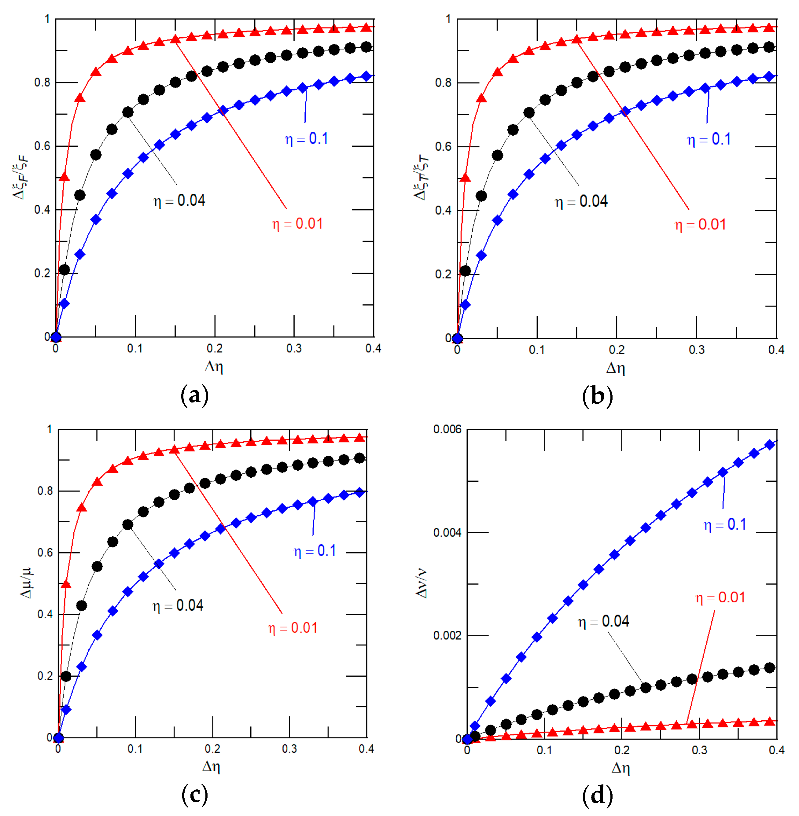
3.2. Impact of Errors in Dimensions, Frequency, and Quality Factor Measurements on the Accuracy of the Present Method

To ensure the proposed procedure of material properties determination is practical, we now examine impact of the dimensional discrepancy and uncertainties in frequency measurements on the determined material properties. It is worth noting that thickness of film can be measured by the ellipsometry with a typical measurement error of sub-nanometer, whereas the cantilever length and width are often determined by a scanning electron microscope with the common uncertainties ranging from few nm to tens of nm. In general, the uncertainties in dimensions, frequency, and Q-factor yield inaccuracies in the determined properties of designed ultrathin films. These inaccuracies expressed through errors in the dimensionless thickness, Δη, density, Δμ, modulus parameters, Δξi, and the Poisson’s ratio, Δυ, can be viewed as a perturbed term in a given quantity. The relative errors calculated from Equations (19)–(21) for η << 1 (i.e., r(ξj, η) ≈ [4ξjη(1+ 1.5η) + 1]/(1 + ξjη)) read:
μ μ = 1 1 + η η 1 ,
ξ i ξ i = 1 1 + 6 η 6 η + 4 R i * + η η 1 ,
υ ¯ υ ¯ = 1 + 4 η ( 1.5 + 2 η ) / B T * 1 + 4 η ( 1.5 + 2 η ) / B F * 1 ,
where υ ¯ = (1 + υ2)/(1 + υ1), R i * and B i * are the measured and calculated properties with due account for uncertainties in the frequency, Q-factor, and dimensions. The achievable relative sensitivity in determined material properties and density of gold film sputtered on the silicon substrate, with dimensions 300 μm (L), 30 μm (W), and 1 μm (T1), are given in Figure 4. For example, for 40 nm thick gold film and the uncertainties in frequency, thickness, and width measurements of 0.5 kHz, 1 and 10 nm, the following properties of gold film are obtained: The Young’s modulus of 78.9 ± 3.3 GPa, the shear modulus of 27.2 ± 0.4 GPa, the density of 20.3 ± 1.2 g/cm3, and the Poisson’s ratio of 0.45 ± 0.1. These results demonstrate that the present procedure of material properties measurement is accurate, even for the relatively high uncertainties in thickness and resonant frequencies (Q-factors) measurements. Importantly, for given measurement errors, the accuracy in determined material properties can be easily improved just by detecting changes in the resonant frequency and Q-factor of the higher vibrational modes (i.e., higher resonant frequencies yield a significant increase in Q-factor values) [38]. For an illustration, we again extract the material properties of 40 nm thick gold film with errors in measurements given in the previous example by considering the second vibrational mode. The calculated properties of gold film using the second vibrational modes are as follows: The Young’s modulus of 78.8 ± 1.4 GPa, the shear modulus of 27.2 ± 0.2 GPa, the density of 20.1 ± 0.9 g/cm3, and the Poisson’s ratio of 0.43 ± 0.1. Different values of film’s Young’s modulus, density and the Poisson’s ratio mainly originate from the uncertainties in calculated Γ j _ r ( ω j ( n ) ) and Γ j _ i m ( ω j ( n ) ) [34,39].

4. Discussion

We now assess the validity and versatility of the proposed procedure of material characterization by extracting the Young’s modulus of the atomic-layer-deposited TiO2 ultrathin film, of thickness 20 and 50 nm, sputtered on the microcantilever made of SU-8 photoresist polymer substrate [46]. In contrast to data presented in [46], where the density of TiO2 film was estimated based on the X-ray reflectometry measurements and, then, the Young’s modulus of TiO2 film was calculated from changes in the resonant frequencies before and after conformal coating of the film, we determine the TiO2 film Young’s modulus without requirement for the density measurement. We remind the reader that the effective linear density of microcantilever vibrating in air can be expressed through measured Q-factor values and, consequently, the simple flexural resonant frequencies of the n-th vibrational mode can be accurately predicted by:
f F 0 ( n ) = γ ( n ) 2 2 π L 2 1 κ F ρ air   W 2 D F Q F ( n ) Γ F _ i m ( ω ) ,
where f = ω / ( 2 π ) and the flexural rigidity of a microcantilever with conformal coating (i.e., the TiO2 film covers entire surface area of the microcantilever) is given by:
D F = 1 12 E 1 W T 1 3 + 1 6 E 2 [ T 1 3 T 2 + T 2 3 ( W + 2 T 2 ) + 3 T 2 ( W + 2 T 2 ) ( T 1 + T 2 ) 2 ] .
For a microcantilever of length, width, and substrate thickness of 300 ± 1 μm, 100 ± 1 μm, and 5.6 ± 0.05 μm, substrate density of 1.2 ± 0.01 g/cm3, and the measured fundamental resonant frequency in air of f F 0 ( 1 ) = 18.2 ± 0.32 kHz, the Young’s modulus of SU-8 substrate of 4.04 ± 0.3 GPa is estimated by Equation (26). Importantly, published experimental data from [46] shows that, in accordance with present theoretical predictions (see Figure 3a,c), coated TiO2 film shifts the microcantilever resonant frequencies to the higher values (i.e., for TiO2 film, stiffness dominates and causes an increase in Q-factor). Accounting for the flexural rigidity given by Equation (27) and structure of Equation (20), the expression enabling calculation of the Young’s modulus of TiO2 film from the experimentally-detected changes in frequency response reads:
ξ F = 1 2 r 0 [ ( f F ( n ) f F 0 ( n ) ) 2 Q F ( n ) Q F 0 ( n ) Γ F _ i m ( ω F ( n ) ) Γ F _ i m ( ω F 0 ( n ) ) 1 ] ,
where r0 = ε2 + η3(1 + 2ε2) + 3η(1 + 2ε2)(1 + η)2 and ε2 = T2/W. Table 1 presents a comparison of the Young’s modulus of 20 and 50 nm thick TiO2 films calculated using Equation (28) and determined previously by Colombi et al. [46].
In addition, comparisons of the shear moduli and densities of 20 and 50 nm thick silicon nitride (Si3N4) films, coated on the silicon microcantilevers of length 300 μm, width 30 μm, and thickness of 1 μm, calculated by the present method (i.e., Equations (19) and (20)) and numerically by using COMSOL Multiphysics, are given in Table 2. The uncertainties in frequency, thickness, and width measurements are: 0.5 kHz, 1, and 10 nm, respectively.
The results given in Table 1 and Table 2 show that here derived expressions enabling calculation of the ultrathin film material properties and density are valid and, in addition, the proposed procedure of material properties determination is relatively simple, practical, universal, and accurate, even for low accuracies in dimensions and frequency measurements.

5. Conclusions

We have proposed and demonstrated the non-destructive and easily accessible method of material characterization utilizing the well-established measurement of static and dynamic modes of the microcantilevers operating in air. Expressions needed to calculate the film properties from measured frequency and Q-factor changes are derived. We have showed that by monitoring changes in resonant frequency and, correspondingly, Q-factor, the Young’s (shear) modulus of film can be determined without the requirement of knowing the film density. This finding would be of great value in material testing of ultrathin films of which the density deviates from known bulk values. The usual discrepancies in dimensions and errors in frequency (Q-factor) measurements were proven to have only a small impact on the calculated material properties of ultrathin film. In addition, for given errors in dimensions and frequency measurements, the accuracy in extracted film properties can be easily improved by using the higher vibrational modes. A good agreement between the Young’s modulus (the shear modulus and density) determined by the present procedure and previous experimental measurements (numerical computations) carried out on the microcantilever, consisting of an elastic substrate and coated ultrathin film(s), has allowed us to confirm the validity of: (a) derived expressions and (b) the present procedure of the ultrathin film material properties determination.

Author Contributions

I.S. proposed the topic, developed the models, and wrote the manuscript. I.S. and L.G. performed the systematic investigations and analysis of data.

Funding

This work was supported by Harbin Institute of Technology, Shenzhen, Shenzhen, China, the project of Czech Republic SOLID 21 (CZ.02.1.01/0.0/0.0/16_019/0000760) and Drážní revize s.r.o.

Conflicts of Interest

The authors declare no conflicts of interest.

References

  1. Cerdán-Pasarán, A.; López-Luke, T.; Esparza, D.; Zarazúa, I.; De la Rosa, E.; Fuentes-Ramírez, R.; Alatorre-Ordaz, A.; Sánchez-Solís, A.; Torres-Castro, A.; Zhang, J.Z. Photovoltaic properties of multilayered quantum dot/quantum rod-sensitized TiO2 solar cells fabricated by SILAR and electrophoresis. Phys. Chem. Chem. Phys. 2015, 17, 18590–18599. [Google Scholar] [CrossRef] [PubMed]
  2. Yunin, P.A.; Drozdov, Y.N.; Drozdov, M.N.; Korolev, S.A.; Lobanov, D.N. Study of multilayered SiGe semiconductor structures by X-ray diffractometry, grazing-incidence X-ray reflectometry, and secondary-ion mass spectrometry. Semiconductors 2013, 47, 1556–1561. [Google Scholar] [CrossRef]
  3. Matsuda, T.; Ishihara, H. Proposal of highly efficient photoemitter with strong phonon-harvesting capability and exciton supperradiance. Appl. Phys. Lett. 2017, 111, 063108. [Google Scholar] [CrossRef]
  4. Li, D.; Jiang, Y.; Zhang, P.; Shan, D.; Xu, J.; Li, W.; Chen, K. The phosphorus and boron co-doping behaviors at nanoscale in Si nanocrystals/SiO2 multilayers. Appl. Phys. Lett. 2017, 110, 233105. [Google Scholar] [CrossRef]
  5. Stachiv, I.; Sittner, P.; Olejnicek, J.; Landa, M.; Heller, L. Exploiting NiTi shape memory alloy films in design of tunable high frequency microcantilever resonators. Appl. Phys. Lett. 2017, 111, 213105. [Google Scholar] [CrossRef]
  6. Stachiv, I.; Sittner, P. Nanocantilevers with adjustable static deflection and significantly tunable spectrum resonant frequencies for applications in nanomechanical mass sensors. Nanomaterials 2018, 8, 106. [Google Scholar] [CrossRef] [PubMed]
  7. Stachiv, I.; Fang, T.-H.; Jeng, Y.-R. Mass detection in viscous fluid utilizing vibrating micro- and nanomechanical mass sensors under applied axial tensile force. Sensors 2015, 15, 19351–19368. [Google Scholar] [CrossRef]
  8. Ceccacci, A.C.; Chen, C.; Hwu, E.; Morelli, L.; Bose, S.; Bosco, F.G.; Schmid, S.; Boisen, A. Blu-Ray-based micromechanical characterization platform for biopolymer degradation assessment. Sens. Actuators B Chem. 2017, 241, 1303–1309. [Google Scholar] [CrossRef] [Green Version]
  9. Stachiv, I.; Fedorchenko, A.I.; Chen, Y.L. Mass detection by means of the vibrating nanomechanical resonators. Appl. Phys. Lett. 2012, 100, 093110. [Google Scholar] [CrossRef]
  10. Hanay, M.S.; Kelber, S.; Naik, A.K.; Chi, D.; Hentz, S.; Bullard, E.C.; Colinet, E.; Duraffourg, L.; Roukes, M.L. Single-protein nanomechanical mass spectrometry in real time. Nat. Nanotechnol. 2012, 7, 602–608. [Google Scholar] [CrossRef]
  11. Sage, E.; Sansa, M.; Fostner, S.; Defoort, M.; Gély, M.; Naik, A.K.; Morel, R.; Duraffourg, L.; Roukes, M.L.; Alava, T.; et al. Single-particle mass spectrometry with arrays of frequency-addressed nanomechanical resonators. Nat. Commun. 2018, 9. [Google Scholar] [CrossRef] [PubMed]
  12. Stachiv, I. Impact of surface and residual stresses and electro-/magnetostatic axial loading on the suspended nanomechanical based mass sensors: A theoretical study. J. Appl. Phys. 2014, 115, 214310. [Google Scholar] [CrossRef]
  13. Kim, M.G.; Kanatzidis, M.G.; Faccheti, A.; Marks, T.J. Low temperature fabrication of high-performance metal oxide thin-film electronics via combustion process. Nat. Mater. 2011, 10, 382–388. [Google Scholar] [CrossRef] [PubMed]
  14. Oliver, W.C.; Pharr, G.M. An improved technique for determining hardness and elastic modulus using load and displacement sensing indentation experiments. J. Mater. Res. 1992, 7, 1564–1583. [Google Scholar] [CrossRef]
  15. Vlassak, J.J.; Nix, W.D. A new bulge test technique for the determination of Young’s modulus and Poisson’s ratio of thin film. J. Mater. Res. 1992, 7, 3242–3249. [Google Scholar] [CrossRef]
  16. Srikar, V.T.; Spearing, S.M. A critical review of microscale mechanical testing methods used in the design of micromechanical systems. Exp. Mech. 2003, 43, 238–247. [Google Scholar] [CrossRef]
  17. Xiang, H.F.; Xu, Z.X.; Roy, V.A.L.; Che, C.M.; Lai, T.P. Method for measurement of the density of thin films of small organic molecules. Rev. Sci. Instrum. 2007, 78, 034104. [Google Scholar] [CrossRef] [PubMed] [Green Version]
  18. Xu, J.; Umehara, H.; Kojima, I. Effect of deposition parameters on composition, structures, density and topography of CrN films deposited by r.f. magnetron sputtering. Appl. Surf. Sci. 2002, 201, 208–218. [Google Scholar] [CrossRef]
  19. Whiteside, P.J.D.; Chinisis, J.A.; Hunt, H.K. Techniques and challenges for characterizing metal thin films with application in photonics. Coatings 2016, 6, 35. [Google Scholar] [CrossRef]
  20. Tsai, P.C.; Jeng, Y.R.; Lee, J.T.; Stachiv, I.; Sittner, P. Effects of carbon nanotube reinforcement and grain size refinement mechanical properties and wear behaviors of carbon nanotube/copper composites. Diam. Relat. Mater. 2017, 74, 197–204. [Google Scholar] [CrossRef]
  21. Carlton, C.E.; Ferreira, P.J. In Situ TEM nanoindentation of nanoparticles. Micron 2012, 43, 1134–1139. [Google Scholar] [CrossRef] [PubMed]
  22. Ma, S.; Huang, H.; Lu, M.; Veidt, M. A simple resonant method that can simultaneously measure elastic modulus and density of thin films. Surf. Coat. Technol. 2012, 209, 208–211. [Google Scholar] [CrossRef]
  23. Stachiv, I.; Zapomel, J.; Chen, Y.L. Simultaneous determination of the elastic modulus and density/thickness of ultrathin films utilizing micro-/nanoresonators under applied axial force. J. Appl. Phys. 2014, 115, 124304. [Google Scholar] [CrossRef]
  24. Illic, B.; Krylov, S.; Craighead, H.C. Young’s modulus and density measurements of thin atomic layer deposited films using resonant nanomechanics. J. Appl. Phys. 2010, 108, 044317. [Google Scholar] [CrossRef]
  25. Stachiv, I.; Vokoun, D.; Jeng, Y.R. Measurement of Young’s modulus and volumetric mass density / thickness of ultrathin films utilizing resonant based mass sensors. Appl. Phys. Lett. 2014, 104, 083102. [Google Scholar] [CrossRef]
  26. Dufrene, Y.F.; Martinez-Martin, D.; Medalsy, I.; Alsteens, D.; Muller, D.J. Multiparametric imaging of biological systems by force-distance curve–based AFM. Nat. Methods 2013, 10, 847–854. [Google Scholar] [CrossRef] [PubMed]
  27. Moreland, J. Micromechanical instruments for ferromagnetic measurements. J. Phys. D Appl. Phys. 2003, 36, R39–R51. [Google Scholar] [CrossRef]
  28. Hwang, K.S.; Lee, J.H.; Park, J.; Yoon, D.S.; Park, J.H.; Kim, T.S. In-Situ quantitative analysis of a prostate-specific antigen (PSA) using a nanomechanical PZT cantilever. Lab Chip 2004, 4, 547–552. [Google Scholar] [CrossRef]
  29. Sandberg, R.; Mølhave, K.; Boisen, A.; Svendsen, W. Effect of gold coating on the Q-factor of a resonant cantilever. J. Micromech. Microeng. 2005, 15, 2249–2253. [Google Scholar] [CrossRef]
  30. Lachut, M.J.; Sader, J.E. Effect of surface stress on the stiffness of cantilever plates. Phys. Rev. Lett. 2007, 99, 206102. [Google Scholar] [CrossRef]
  31. Karabalin, R.B.; Villanueva, L.G.; Matheny, M.H.; Sader, J.E.; Roukes, M.L. Stress-induced variation in the stiffness of micro- and nanocantilever beams. Phys. Rev. Lett. 2012, 108, 236101. [Google Scholar] [CrossRef] [PubMed]
  32. Pini, V.; Ruz, J.J.; Kosaka, P.M.; Malvar, O.; Calleja, M.; Tamayo, J. How two-dimensional bending can extraordinary stiffen thin sheets. Sci. Rep. 2016, 6, 29627. [Google Scholar] [CrossRef] [PubMed]
  33. Ruz, J.J.; Pini, V.; Malvar, O.; Kosaka, P.M.; Calleja, M.; Tamayo, J. Effect of surface stress induced curvature on the eigenfrequencies of microcantilever plates. AIP Adv. 2018, 8, 105213. [Google Scholar] [CrossRef]
  34. Sader, J.E. Frequency response of cantilever beams immersed in viscous fluids with applications to the atomic force microscope. J. Appl. Phys. 1998, 84, 64–76. [Google Scholar] [CrossRef] [Green Version]
  35. Stachiv, I.; Fang, T.H.; Chen, T.H. Micro-/nanosized cantilever beams and mass sensors under applied axial tensile/compressive force vibrating in vacuum and viscous fluid. AIP Adv. 2015, 5. [Google Scholar] [CrossRef]
  36. Zapomel, J.; Stachiv, I.; Ferfecki, P. A novel method combining Monte Carlo–FEM simulations and experiments for simultaneous evaluation of the ultrathin film mass density and Young’s modulus. Mech. Syst. Signal Process. 2016, 66–67, 223–231. [Google Scholar] [CrossRef]
  37. Kelly, S.G. Fundamentals of Mechanical Vibrations, 2nd ed.; McGraw-Hill International: Singapore, 2000. [Google Scholar]
  38. Chon, J.W.M.; Mulvaney, P.; Sader, J.E. Experimental validation of theoretical models for the frequency response of atomic force microscope cantilever beams immersed in fluids. J. Appl. Phys. 2000, 87, 3978–3988. [Google Scholar] [CrossRef]
  39. Van Eysden, C.A.; Sader, J.E. Frequency response of cantilever beams immersed in viscous fluids with applications to the atomic force microscope: Arbitrary mode number. J. Appl. Phys. 2007, 101, 044908. [Google Scholar] [CrossRef]
  40. Van Eysden, C.A.; Sader, J.E. Small amplitude oscillations of a flexible thin blade in a viscous fluid: Exact analytical solution. Phys. Fluids 2006, 18, 123102. [Google Scholar] [CrossRef] [Green Version]
  41. Green, C.P.; Sader, J.E. Torsional frequency response of cantilever beams immersed in viscous fluids with applications to the atomic force microscope. J. Appl. Phys. 2002, 92, 6262–6274. [Google Scholar] [CrossRef] [Green Version]
  42. Gupta, A.K.; Nair, P.R.; Akin, D.; Ladisch, M.R.; Broyles, S.; Alam, M.A.; Bashir, R. Anomalous resonance in a nanomechanical biosensor. Proc. Natl. Acad. Sci. USA 2006, 103, 13362–13367. [Google Scholar] [CrossRef] [PubMed] [Green Version]
  43. Tamayo, J.; Ruz, J.J.; Pini, V.; Kosaka, P.; Calleja, M. Quantification of the surface stress in microcantilever biosensors: Revisiting Stoney’s equation. Nanotechnology 2012, 23, 475702. [Google Scholar] [CrossRef] [PubMed]
  44. Sader, J.E. Surface stress induced deflections of cantilever plates with applications to the atomic force microscope: Rectangular plates. J. Appl. Phys. 2001, 89, 2911–2921. [Google Scholar] [CrossRef] [Green Version]
  45. Morin, P.; Raymond, D.; Benoit, P.; Maury, P.; Beneyton., R. A comparison of the mechanical stability of silicon nitride films deposited with various techniques. Appl. Surf. Sci. 2012, 260, 69–72. [Google Scholar] [CrossRef]
  46. Colombi, P.; Bergese, P.; Bontempi, E.; Borgese, L.; Federici, S.; Keller, S.S.; Boisen, A.; Depero, L.E. Sensitive determination of the Young’s modulus of thin films by polymeric microcantilevers. Meas. Sci. Technol. 2013, 24, 125603. [Google Scholar] [CrossRef]
Figure 1. Sketch of the two-layered microcantilever made of an elastic substrate and coated ultrathin film performing (a) flexural and (b) torsional oscillations.
Coatings 09 00486 g001
Figure 2. Calculated dependencies of the real and imaginary components of the hydrodynamic function on the fundamental resonant frequency of a rectangular two-layered microcantilever (see Figure 1) immersed in air, represented through the Reynolds number for (a) flexural and (b) torsional oscillations.
Coatings 09 00486 g002
Figure 3. Dependencies of (a,b) the fundamental resonant frequencies and, correspondingly, (c,d) Q-factors of the silicon cantilever on film thickness for flexural and torsional vibrational modes.
Coatings 09 00486 g003
Figure 4. The achievable relative sensitivity of (a) the Young’s modulus (Equation (24)); (b) the shear modulus (Equation (24)); (c) density (Equation (23)); and (d) the Poisson’s ratio (Equation (25)) of gold film of η = 0.01, 0.04, and 0.1 coated on the silicon substrate with dimensions 300 μm (L), 30 μm (W), and 1 μm (T1).
Coatings 09 00486 g004
Table 1. Comparison of the Young’s modulus of atomic layer deposition (ALD) TiO2 films calculated by Equation (28) and determined previously in [46].
Measured QuantitySU-820 nm TiO250 nm TiO2
Frequency in air (kHz)18.2 ± 0.3221.0 ± 0.2127.1 ± 0.18
QF/QF0None1.11 ± 0.0181.34 ± 0.019
Young’s modulus (GPa), by Equation (28)4.04 ± 0.3066.3 ± 1496.9 ± 8
Young’s modulus (GPa), [34]3.82 ± 0.1360 ± 1891 ± 15
Table 2. Comparisons of the shear modulus and density of silicon nitride film coated on the silicon microcantilever obtained by the proposed procedure and numerically. Considered errors in frequency, thickness, and width measurements are: 0.5 kHz, 1, and 10 nm, respectively.
Measured Quantity20 nm Si3N450 nm Si3N4
ωT/ωT0, Equation (17)/Numerically1.024 ± 0.003/1.026 ± 0.0031.058 ± 0.003/1.061 ± 0.003
QT/QT0, Equation (18)/Numerically1.045 ± 0.002/1.048 ± 0.0021.114 ± 0.002/1.116 ± 0.002
Density (g/cm3), Equation (19)/Numerically3.35 ± 0.01/3.52 ± 0.023.25 ± 0.01/3.26 ± 0.01
Shear modulus (GPa), Equation (20)/Numerically100.48 ± 10.77/107.64 ± 11.11100.39 ± 4.67/104.01 ± 4.74

