Article

Stress Corrosion Cracking Resistance of Cold-Sprayed Al 6061 Deposits Using a Newly Developed Test Fixture

1
Department of Mechanical Engineering, Bucknell University, Lewisburg, PA 17837, USA
2
Applied Research Laboratory, University Park, The Pennsylvania State University, State College, PA 16802, USA
3
U.S. Army Research Laboratory, Weapons and Materials Research Directorate, Aberdeen Proving Ground, MD 21005, USA
*
Author to whom correspondence should be addressed.
Coatings 2019, 9(7), 445; https://doi.org/10.3390/coatings9070445
Submission received: 10 June 2019 / Revised: 9 July 2019 / Accepted: 11 July 2019 / Published: 17 July 2019
(This article belongs to the Special Issue Cold Spraying: Recent Trends and Future Views)

Abstract

:
The stress corrosion cracking (SCC) response of Al 6061 bulk deposits produced by high-pressure cold spray (HPCS) was investigated and compared to commercial wrought Al 6061-T6 material. Representative tensile coupons were stressed to 25%, 65% and 85% of their respective yield strength and exposed to ASTM B117 salt fog for 90 days. After exposure, the samples were mechanically tested to failure, and subsequently investigated for stress corrosion cracking via optical and scanning electron microscopy with energy-dispersive X-ray spectroscopy (EDS). The results were compared to the wrought Al 6061-T6 properties and correlated with the observed microstructures. Wrought samples showed the initiation of stress corrosion cracking, while the cold-sprayed deposits appeared to be unaffected or affected by general corrosion only. Optical microscopy revealed evidence of stress corrosion cracking in the form of intergranular corrosion in the wrought samples, while no significant corrosion was observed in the cold-sprayed deposits. Fractography revealed wrought samples failed due to multiple mechanisms, with predominant cleavage and intergranular failure, but cold-sprayed samples only failed by ductile dimple rupture. The difference in SCC response between the differently processed materials is attributed to the documented benefits of the cold spray process, which includes maintaining fine grain structure of the feedstock powder and high density after consolidation, low oxidation, and work hardening effect.

1. Introduction

Recently, efforts to produce highly dense, bulk components with high strength and ductility have shifted focus from traditional metallurgy methods, which have limitations, to the cold spray process [1,2,3,4]. Cold spray is a relatively new technology derived from other thermal spray processes. The cold spray process involves the acceleration of micron-sized particles in the solid state toward a target, upon which the surface of the powder particle undergoes high levels of plasticity. This plasticity helps to break down surface contaminants on both the powder and substrate (which can be the target or the prior deposited layers of cold spray) leading to a metallic and mechanical bond. The bulk of the powder also undergoes plasticity, but to a much lesser extent than the surface. Because the material is deposited in the solid state, the microstructure prior to spraying remains relatively intact after spraying, with the exception of some dynamic recrystallization due to high strain levels. Also, because the process requires high levels of plasticity, it is important to have a feedstock material that can undergo high levels of strain with low energy input, but also work-harden sufficiently to obtain the strength required. The cold spray process can also produce near-net shapes before machining to final components, making it a possible method for three-dimensional (3D) manufacturing. Unlike thermal spray methods or conventional manufacturing processes, the main advantages of using cold spray is that it can produce coatings and bulk materials with no recrystallization, thus maintaining the structure and size of starting powders. As a low-temperature process, it operates below the melting point of metals and results in very low porosity deposits without the need for combustible gasses. Additional motivation to use this process is the low oxide content, which can improve corrosion resistance, mechanical properties, and wear resistance by eliminating sites for localized corrosion and premature failure.
There has been a great deal of research into corrosion mechanisms in metallic materials over the past century [5,6,7,8,9,10,11,12,13,14,15,16,17]. Atmospheric or environmentally assisted corrosion is one of the least understood areas of corrosion. Stress corrosion cracking is a type of atmospheric corrosion that is very difficult to detect and mitigate, since it only occurs in alloys that have been under stress in corrosive environments. Metallic materials used extensively in engineering and defense applications are susceptible to corrosion. Corrosion costs the US billions of dollars per year in preventative maintenance and product loss. There are many different types of corrosion that can attack metallic materials, which include uniform corrosion, galvanic corrosion, crevice corrosion, pitting and environmentally induced corrosion. The environment the material is exposed to has a major effect on how it corrodes. The three main types of environmental corrosion that lead to cracking are: corrosion fatigue, hydrogen induced, and stress corrosion (SCC). Stress corrosion cracking is the formation of cracks in a material that form due to corrosion while a part is exposed to tensile stresses.
Pure metals are typically resistant to stress corrosion cracking, but metallic alloys such as stainless steel and aluminum alloys are susceptible due to the large amount of alloying elements in the matrix. Typically, alloys rely on intermetallic formation at the grain boundaries to increase strength and ductility. Consequently, the intermetallics cause an anodic condition at the grain boundaries, which in turn causes preferential intergranular corrosion in aluminum alloys. Dealloying is associated with stress corrosion cracking in aluminum alloys, steels, and noble metal alloys such as AgAu and CuAu [14,15,16]. Renner et al. [17] noted that cracks can form in CuAu alloys during local dealloying and depend on the crystallographic orientation of the substrate material and stability of applied inhibitor layers. Higher strength alloys such as the 7xxx and the 2xxx alloys are more susceptible to SCC [18,19,20,21,22] due to the high alloying additions. The 6xxx series alloys are usually not as susceptible to SCC when exposed to high tensile stresses and highly corrosive atmospheres [18,21,22,23]. For the most part, the service record of 6xxx alloys shows no reported cases of SCC. But in accelerated laboratory tests where high stresses and aggressive solutions are used, cracking has been observed [18,23]. These results were predominately demonstrated in alloys with high alloy content and containing silicon in excess of the Mg2Si ratio and/or high percentages of copper [23]. Aluminum alloy 6061-T6 (peak-aged) is typically not susceptible to this type of corrosion, but more understanding of this behavior is required, as published research in this area is often contradictory.
As high-pressure cold spray (HPCS) continues to gain interest in various applications such as repair, wear and corrosion resistance, there is a necessity to understand the effects of the processing parameters and resulting microstructure and mechanical/corrosion performance of defense-related alloys produced by cold spray. Postdeposition heat treatments are often used in cold-sprayed materials to improve ductility [24,25,26,27]. In precipitation-hardened alloys, such as Al 6061 that is used in various defense applications, it is important to consider the effect the heat treatment may have on corrosion resistance and precipitation strengthening. Cold-sprayed materials which are synthesized by severe plastic deformation can result in varied precipitation strengthening performance when compared with that of conventionally processed materials. As a result, finding an optimized heat treatment for cold-sprayed materials of the same material class can be challenging. Thus, evaluating material performance in the as-sprayed condition can provide a useful starting point.
This paper studies the effect of the high-pressure cold spray process on the SCC performance of Al 60601 alloy in an aggressive corrosive environment. Mechanical properties of bulk as-sprayed and annealed cold-sprayed material were first evaluated and compared to wrought Al 6061-T6 values. Since preliminary tensile data for the cold-sprayed 6061 was close to the wrought values (other than % elongation), it was decided that the SCC performance of the materials would be compared in these respective processing conditions. Furthermore, Rokni et al. [24] observed that ultimate tensile strength did not substantially increase with subsequent heat treatment after deposition. They noted that the increase in ultimate tensile strength (UTS) for the solution-treated and peak-aged cold-sprayed Al 6061 was relatively small. Knowing that precipitates can have negative affect on corrosion behavior, it was decided to compare cold spray materials in the as-deposited and annealed conditions to wrought material in the peak-aged condition. Resulting microstructures and fracture surfaces in this study were evaluated through scanning electron microscopy with energy dispersive X-ray spectroscopy (EDS) and optical microscopy after corrosion exposure and tensile testing to failure.

2. Materials and Methods

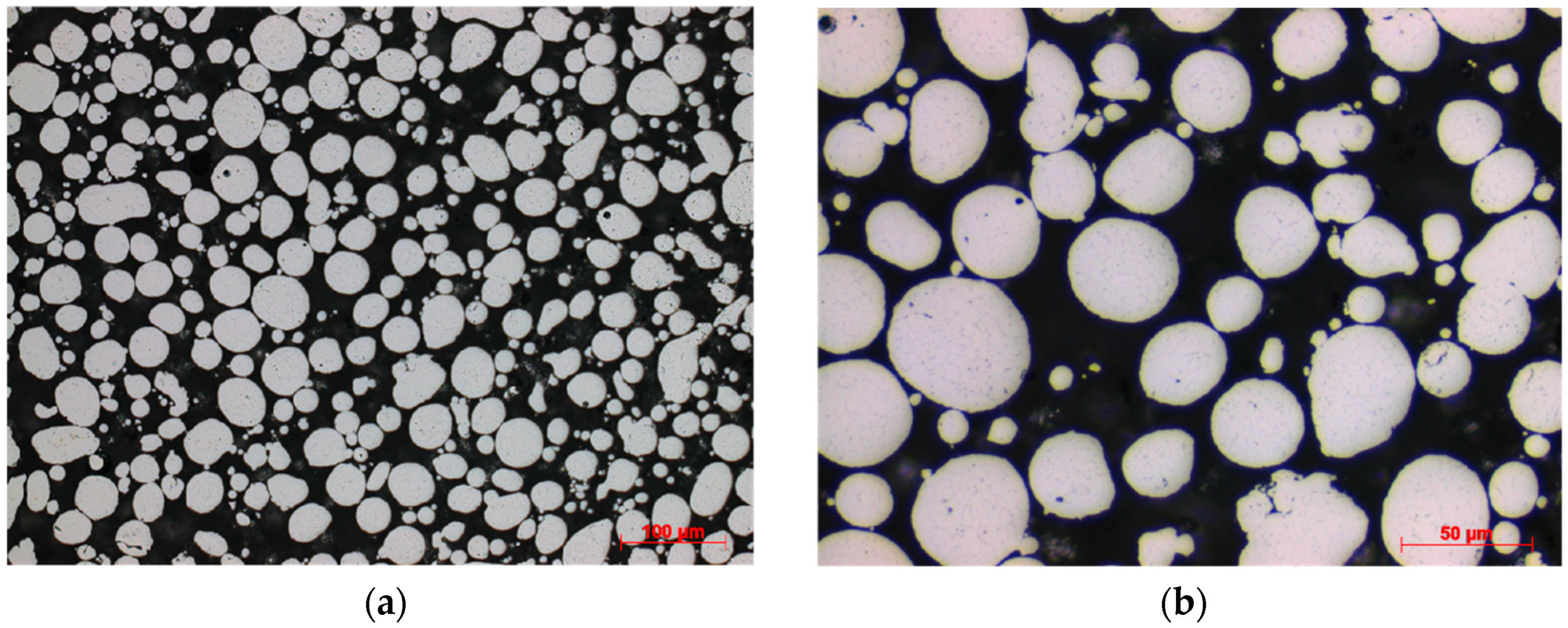
2.1. Feedstock Powders

All powders were produced by Valimet Inc. (Stockton, CA, USA) by inert gas atomization. Most production of aluminum powder uses a process of inert gas atomization. In this process, an inert or semi-inert gas like argon, helium, and even sometimes nitrogen is used to spray a molten stream of aluminum, atomizing it into fine particles. The Al 6061 powder particles are relatively spherical in appearance (Figure 1). Spherical aluminum particle morphology provides good consolidation characteristics, with high deposit efficiency and results in a microstructure containing low porosity and high hardness/strength. The specified particle size cut was −325 mesh, which corresponds to a maximum particle size of approximately 44 μm. Particle size and morphology was confirmed using a Horiba LA-910 laser scattering particle size distribution analyzer (Horiba, Kyoto, Japan) and an environmental scanning electron microscope (ESEM, Quanta 200, FEI, Hillsboro, OR, USA). The average Al 6061 feedstock particle size was approximately 18 μm (D50). Figure 2 shows the particle size distribution for the 6061 powders.

2.2. Sample Preparation

The first major technical challenge was development and optimization of the cold spray process parameters. Particle velocities and temperatures are two of the key variables in the cold spray process. Modeling these variables saved significant costs by eliminating iterative and extraneous experimentation. Army Research Laboratory’s (Adelphi, MD, USA) propriety cold spray computer model was used for this effort. Input variables include, but are not limited to, nozzle geometry, carrier gas type, particle density, gas viscosity, operating pressure, gas temperatures and particle size. Particle temperature and particle velocity at the substrate are the two of the variables which are actually modeled. The modeling program also provides estimates for deposition efficiency as well as coating cost per area. Both of these estimates are extremely practical tools which aid implementation. Other parameters such as robot raster speed, nozzle material and stand-off distance were optimized for aluminum coatings during the trials. Specific coating compositions, carrier gases and nozzle designs are provided in Table 1.
The SCC specimens were fabricated from both bulk cold-sprayed and wrought material. The wrought Al 6061-T6 samples were used as a baseline. All samples were fabricated using wire electrical discharge machining (EDM). For the wrought samples, a 0.125″ thick plate of Al 6061-T6 was cut into 4″ × 6″ rectangular sections. Flat tensile bar specimens were machined in accordance to ASTM E8, Standard Test Method for Tension Testing of Metallic Materials [28]. The samples were 4″ in length by 0.375″ in width in the grip section and 0.25″ in the gage section. The samples were inspected for machining defects, and any burrs were removed using a file.
For the cold-sprayed bulk samples, two blocks of cold-sprayed Al 6061 were provided by the Army Research Laboratory. They were manufactured by depositing a cold-sprayed 0.375″ thick layer of Al 6061 on to a 0.50″ thick plate of wrought Al 6061-T6. After deposition, the aluminum coating was machined to a uniform thickness of 0.20″. To accomplish this task, the block was placed in a Bridgeport vertical mill (Bridgeport, CT, USA) and the coating was machined using a ¾″ diameter titanium aluminum nitride coated carbide end mill (Niagara Cutter LLC, Reynoldsville, PA, USA). The cross section and isometric views of the aluminum blocks are shown in Figure 3. A wire electrical discharge machining (EDM) process was used to separate the cold spray coating from the substrate. Tensile specimens were subsequently cut from the cold spray material following ASTM E8, to the same dimensions and method as the wrought specimens. The grip areas of the samples were anodized to a type 3 condition to minimize galvanic corrosion between the test specimen and the test fixture.

2.3. Test Procedure and Fixture Development

Following ASTM standard G64-99 (2013), Standard Classification of Resistance to Stress-Corrosion Cracking of Heat-Treatable Aluminum Alloys [29], the stress levels for the wrought were 0%, 25%, 65% and 85% of the specified minimum yield strength for wrought Al 6061-T6 (270 MPa). The cold-sprayed material was tested at 25%, 65% and 85% of the minimum yield strength, 270-MPa, since preliminary tensile data for the cold-sprayed Al 6061 was close to the wrought values (other than % elongation). The stress levels were achieved by mounting the tensile bars into a corrosion-resistant uniaxial stress fixture, shown in Figure 4. The tensile test fixtures were developed by Pennsylvania State University (PSU, State College, PA, USA)/ARL and were designed to withstand extended periods of time in the ASTM B117 [30] salt fog environment.
The fixtures were made from 316L stainless steel and have a polymer spring system that can be adjusted to apply a constant force on the sample depending on the compression of the spring. An estimate for the required compression amount can be made by using values from the yield strength and Hooke’s law. Before testing occurred, the fixtures were calibrated using Fiber Bragg Grating (FBG) sensors (Micron Optics, Atlanta, GA, USA) to ensure that the compression was accurate and did not creep over time. Figure 5 shows the results from a fixture loaded to 80% of the yield strength of Al 6061-T6. There was little change in the applied load, even during long-term testing.
The moving parts in the tension fixtures were coated with anti-seize lubricant to prevent galvanic corrosion from occurring between sample and fixture. Each fixture was subsequently compressed to the desired percentage of the Al 6061-T6 yield strength by turning the nuts on the threaded rod. The initial distance between the faces of each stainless steel clamp were noted at assembly. This distance was then compressed to the calculated compression distance. The sample was then placed into the fixture; the clamps were bolted down and torqued to 35 ft-lb in an alternating pattern. Once the clamps were in place and bolted, the threaded rod was loosened, applying a constant force to the aluminum sample. The loaded fixtures were then placed in the cyclic salt fog (SF) chamber for test duration of 90 days. The samples were photographed and inspected periodically during testing. Test duration was determined using ASTM G64 [29] and was the recommended maximum exposure period to determine intergranular SCC while avoiding excessive pitting. Test parameters for ASTM B117, Standard Practice for Operating Salt Spray (Fog) Apparatus were followed and are shown in Table 2.
Samples were tensile-tested to failure after 90 days of exposure to ASTM B117 salt fog. A screw-driven tensile frame (Instron 5866, Norwood, MA, USA) was used for all testing, which was conducted following the ASTM E8 standard at a strain rate of 0.015 mm/mm/min. A 25 mm resolution extensometer was mounted to each sample to measure strain, and a 10 kN load cell (Instron 5866, Norwood, MA, USA) was used to measure load. Each sample’s cross-sectional area was measured with digital calipers (Mitutoyo 500-753-100, Kawasaki, Japan) and used for stress calculation. After testing, the fracture surfaces were preserved for further microscopic analysis. All valid results using at least five specimens per condition (based on ASTM standard) were averaged and are presented for each stress condition.

2.4. Microstructural Characterization

Both mechanical testing and microstructural analysis were performed to characterize the behavior of wrought Al 6061-T6 and cold-sprayed Al 6061 material in a saline environment. This included tensile testing, optical microscopy, and scanning electron microscopy (SEM, NanoSEM 630, FEI, Hillsboro, OR, USA) analysis of fracture surfaces with energy-dispersive X-ray spectroscopy (EDS, NanoSEM 630, FEI, Hillsboro, OR, USA). Specimens were analyzed using a Nikon Epiphot 200 inverted microscope (Tokyo, Japan) and DS-Fil camera head system to capture optical micrograph images. Samples for grain-size analysis were etched using Keller’s reagent (95 pct water, 2.5 pct HNO3, 1.5 pct HCl, 1.0 pct HF) for 10 s. The mean linear intercept method according to the ASTM-E112-12 standard [31] was used to measure average grain size and was recorded using NIS Elements D (version 4.6).

3. Results

3.1. Microstructural Characterization before B117 Salt Fog Exposure

3.1.1. As-Deposited Cold Spray Condition

Figure 6a,b shows the cross-sectional optical microscopy images of the cold spray Al 6061 bulk deposit perpendicular to the spraying direction. The representative microstructures were etched, showing where prior particle boundaries exist. Upon inspection, interparticle voids and porosity can be observed; lower particle-impact velocity and subsequent lack of local deformation in some particles results in these types of imperfections forming in cold spray deposits [32,33,34]. Rokni et al. [24] observed similar microstructure in their as-deposited cold-sprayed Al 6061 materials and found the imperfections to influence the mechanical properties. They also performed electron back-scatter diffraction (EBSD) mapping in order to characterize the grain structure, and in doing so, Roki et al. [24] identified the presence of two distinct regions, particle interiors and prior particle boundary (PPB) regions. The first was characterized by small grain size, approximately 1–10 μm in size and was attributed to significant plastic deformation that occurs in the feedstock powders. The second was described as much smaller grain sizes and was believed to be the result of the pancaking mechanism that results from the continuous buildup of particles. The ultrafine grain structures (UFG) that resulted were attributed to the high plastic deformation at strain rates between 106/s–109/s and moderate temperatures during the consolidation of the deposits. Ultrafine grain structures in cold spray deposits have been observed by numerous researchers [35,36,37,38,39,40,41,42,43], who attributed the result to two types of dynamic recrystallation, continuous and geometric. In this study, the average grain size of the as-deposited Al 6061 material was found to be 25 μm (standard deviation of 14.5). The ultrafine grain sizes can easily be observed in the cold spray material at higher magnification and were observed to range from 1 to 10 μm, as shown in Figure 6b.

3.1.2. As-Received Wrought Al 6061-T6

Figure 7 shows the cross-sectional optical micrograph of wrought Al 6061-T6 in the as-received condition. Irregular distribution of course second-phase particles can be observed throughout the cross section. The effect of these precipitates on the SCC behavior is discussed later in this paper. The average grain size was found to be 78 μm (standard deviation 24 μm).

3.2. Tensile Testing and Residual Strength Calculations

None of the wrought or cold-sprayed samples fractured in the stress frames during the B117 exposure; all samples remained intact after 90 days of exposure until removed from fixtures. Figure 8 shows the representative (average of five samples) stress/strain behavior of the wrought Al 6061-T6 samples that were tensile-tested to failure after 90 days of ASTM B117 salt fog exposure. The samples strained at 85% and 65% of the yield stress displayed similar stress/strain behavior, while the samples strained at 85% displayed a much shorter plastic region and lower strain at fracture. The samples prestrained at 25% of yield had the highest resulting yield and tensile stress after 90 days exposure to the salt fog, while the 85% had the lowest. This result was expected, since higher imposed pre-strains generally result in decreased strength properties, resulting from more aggressive stress corrosion attack.
Figure 9 shows the results from the cold spray Al 6061 samples that were tensile-tested (average of five samples) after 90 days of ASTM B117 salt fog exposure. As expected, the samples strained at 85% of the yield strength had the least amount of plastic deformation and the lowest yield and tensile strength. The samples strained at 25% and 65% of yield strength had similar tensile behavior after exposure, with the 25% displaying a more significant plastic region, a higher tensile strength, and higher strain at fracture. There is no significant difference in the slope of the elastic region, for the most part, but the biggest change is in the plastic region of the stress–strain curves for the cold-sprayed material and is believed to be related to the type of corrosive attack (discussed later). For engineering alloys, this is typically not an issue, since most designs do not come close to the elastic limit of the material.
Figure 10 combines data from Figure 8 and Figure 9 into bar graphs to compare the average values for ultimate tensile strength and yield strength of differently prepared samples at each pre-stress condition. Average values of yield strength ranged from 227 to 191 MPa for the wrought Al 6061-T6 and 251–193 MPa for the cold-sprayed Al 6061 for all samples exposed for 90 days. The yield and tensile strength of the cold spray samples was very close to that of the wrought samples and was slightly higher in most cases, even though they had not been heat-treated. This improved strength in the non-heat-treated condition can be attributed to the cold spray process, where particles experience severe plastic deformation during deposition [1,28,34,37,38]. The grain refinement and strain hardening of the process are mechanisms which assist with this increase in strength when compared with that of conventionally processed Al 6061 [1,28,38,41,42]. Similar behavior has been documented by researchers who studied other manufacturing processes where severe plastic deformation is involved, such as tube channel pressing [43], equal channel angular pressing (ECAP) [44], and high-pressure torsion [45], with increases in UTS from 39% to 92%. Depending on heat treatment and stress condition, the cold-sprayed processing yields results similar or improved over the conventional wrought material, as shown in Figure 10. While the results establish the cold spray process yields improved ultimate tensile strength, the ductility of these materials displayed a marked reduction in ductility (Figure 11). This behavior can be explained by the presence of interparticle voids and localized porosity, in addition to the increased cold work during deposition, as explained in Section 3.1.1.
The percentage of residual strength retained after exposure was calculated and is presented in Figure 11. Most notable is that the cold-sprayed deposits retained a higher percentage of their original tensile strength after 90 days exposure than the wrought samples at both the 25% and 65% of yield stress conditions. This reduction in residual strength is believed to be due to the stress corrosion attack, which developed in the Al 6061-T6 and was the focus of the subsequent microscopic analysis. Conversely, in the 85% of yield stress condition, the wrought material retained more strength than the cold-sprayed Al 6061 deposits. This behavior is attributed to the aggressive loading condition and the predominately mechanical vs. corrosion response of the cold spray deposits, and can be rationalized by understanding the precipitation behavior of the differently processed materials.
Rokni et al. [24,37] characterized cold-sprayed Al 6061 deposits in the as-deposited (AD), stress-relief-annealed (SR) and peak-aged (T-6) conditions to understand the effect of heat treatment on strength and ductility. They observed AD cold sprayed Al 6061 to possess moderate dislocation density and multiple low-angle grain boundaries (LAGB). The microstructure of conventionally processed Al 6061-T6 is well documented and commonly described as containing disc-shaped β, rod-shaped β′, and needle-shaped β″ particles, in addition to fine spherical or needle-shaped Guinier-Preston (GP) zones approximately 5 nm in size [23]. These precipitates are known to be sites for failure and corrosive attack [23,26,27].

3.3. Microstructural Analysis after B117 Exposure

3.3.1. Optical Microscopy

Optical microscopy was performed after 90 days of B117 exposure on all fractured tensile cross sections to better understand the mechanisms of failure. The samples were polished and imaged using a Nikon Epiphot 200 optical microscope using brightfield microscopy in order to identify any indication of stress corrosion cracking. Metallographic sections of stress corrosion cracking samples revealed evidence of pitting and intergranular corrosion at all three stress conditions (Figure 12, Figure 13 and Figure 14) for the wrought Al 6061-T6 samples. Stress corrosion cracking in aluminum alloys is typically intergranular in nature [19]. At all three pre-stressed conditions, cracks nucleated at pits and were highly branched, indicative of stress corrosion cracking (Figure 12, Figure 13 and Figure 14). Braun et al. [22,23] investigated Al 6061 sheet samples using bent-beam specimens (stress was applied in the transverse direction) in the natural and peak-aged conditions that were alternately immersed in 3.5% NaCl solution and found them to only show signs of pitting. It is possible that the wrought samples in the current study show signs of SCC, most likely due to the extremely corrosive atmosphere found in the ASTM B117 salt fog. Braun [23] noted pits reached a maximum depth of 30 μm, while pits in the current study were much deeper, the size increasing with pre-stress condition. In the 25% of yield stress condition (Figure 12), the wrought Al 6061-T6 displayed pits approximately 350 μm in size, with a maximum pit depth of 450 μm. Maximum depths of attack including branching reached up to 750 μm, with the average depth of combined attack being approximately 400 μm. In the 65% of yield stress condition, maximum pit depths grew to 600 μm, with combined depths of attack which ranged from 150 to 750 μm (Figure 13). When wrought samples were stressed to 85% of yield stress, the maximum pit depth increased to 750 μm, with average crack branching attack reaching an additional 250 μm; average depths of attack ranged between 250 and 650 μm (Figure 14). Under static loading, Braun [23] tested Al 6061 sheet in the peak-aged condition using an aqueous chloride–bicarbonate solution. After 30 days, he observed pitting and intergranular corrosion extending up to 210 μm in his samples [23], which is similar to what was observed in this study. The occurrence of stress corrosion cracking is also supported in the fractography of the failed specimen and is discussed later.
Results of optical analysis (Figure 15a–c) of the cold spray samples did not show any evidence of stress corrosion cracking at any of the stress conditions. The samples showed negligible general corrosion on the surface (Figure 15a,b) in the 25% and 65% yield stress conditions. This is in contrast to the wrought samples, which showed evidence of pitting and intergranular corrosion at the surface in the same stress condition. At the 85% yield stress condition, the cold spray deposit did show signs of some corrosive attack, although intergranular attack, pitting, or branching was not obvious (Figure 15c).

3.3.2. Fractography

Scanning electron microscopy (SEM) was used to analyze the fracture surfaces of both the wrought and cold-sprayed samples to obtain more information about the failure mechanism. Figure 16 and Figure 17 show the SEM micrographs of the fracture surfaces for wrought Al 6061-T6 samples after 90 days of ASTM B117 salt fog exposure. The samples appear to have failed due to multiple mechanisms, as characterized by two primary features: (1) few fine dimples showing microvoid coalescence with associated tearing, and (2) smooth regions suggesting particle-to-particle fracture. In the wrought sample strained to 25% yield (Figure 16a), although few fine dimples exist, the fractography predominately shows intergranular fracture; Figure 16b shows the grain boundaries have been attacked. This type of failure is caused by elemental depletion at the grain boundary or weakening of the grain boundaries from oxidation, chemical attack, or embrittlement [17,27,46,47]. Figure 17a,b also shows additional transgranular fracture. This fracture behavior corresponds with the ASM handbook on aluminum alloys evaluating stress corrosion cracking and compliments the optical analysis by previous researchers [24,47]. The smooth regions indicate fast fracture through rapid crack propagation as a result of brittle behavior and low ductility (low strain to failure) and explains the similar and decreased strain to failure when compared with that of the cold-sprayed deposits. Figure 18a–c shows the SEM micrographs of the fracture surfaces for the cold spray Al 6061 deposits after 90 days of ASTM B117 salt fog exposure. These samples show evidence of predominate failure by ductile dimple rupture and void coalescence, although smooth regions attributed to particle–particle fracture can also be observed and are identified by arrows.

3.4. Stress Corrosion Cracking

Research has determined that the effects of heat treatment, grain size, grain boundary segregation and precipitates, hydrogen embrittlement, as well as the loading mode, all have an influence on the SCC resistance of aluminum alloys [5,6,7]. Various studies have also shown that the stress corrosion cracking behavior of aluminum alloys in chloride environments is largely dependent on the specific immersion conditions [18,19,44,45,46]. Additionally, precipitates can cause areas of localized corrosion because of differences in corrosion potential as compared with surrounding areas, resulting in hydrogen evolution, promoting SCC [7,8,9,10,17,48,49]. The build-up of hydrogen can eventually embrittle the material and cause cracking [11,12,13]. Since the cold spray deposit was in the as-deposited condition, while the wrought Al 6061 in the T6, EDS was conducted to evaluate the elemental differences in fracture surfaces between the two materials. Wrought fracture surfaces showed a presence of second-phase particles rich in Mg, Si and Fe, as shown in Figure 19. Conversely, the cold-sprayed deposit fracture surfaces show evenly distributed elemental mapping free of segregation. There were some random inclusions observed, as shown in Figure 20.
Based on the microstructural analysis, it can be concluded that the wrought samples failed by stress corrosion cracking, while the cold-sprayed samples failure was predominately by mechanical means. It has been well established that powder metallurgy (PM) methods can produce materials with fine metallurgical structures and compositions, which make such materials more resistant to stress corrosion cracking [5,6]. The cold spray process can also produce materials that have a very fine grain size, which is dictated by the starting feedstock powder. The fine grain size of the powder is maintained in the bulk deposit. This inherent characteristic becomes even more pronounced when producing aluminum cold spray materials, because there can be a great disparity in grain size between the cold spray Al 6061 material (Figure 6) and its wrought counterpart (Figure 7). The difference in average grain size is approximately 53 μm, and therefore, the SCC results were expected and substantiate previous research of PM materials.

4. Conclusions

In this preliminary study, the stress corrosion cracking response of cold spray deposits was compared to wrought counterparts that were peak-aged. Following ASTM standard G64-99 (2013), Standard Classification of Resistance to Stress-Corrosion Cracking of Heat-Treatable Aluminum Alloys, the stress levels for the wrought were 0%, 25%, 65% and 85% of the specified minimum yield strength for Al 6061-T6, while the cold-sprayed deposits were evaluated at 25%, 65% and 85% of the minimum yield strength. SCC test fixtures were developed at PSU/ARL and were designed to withstand extended periods of time in the ASTM B117 salt fog environment without galvanic interaction. Nonfailed samples that were exposed for 90 days were subsequently tensile tested to obtain residual strength.
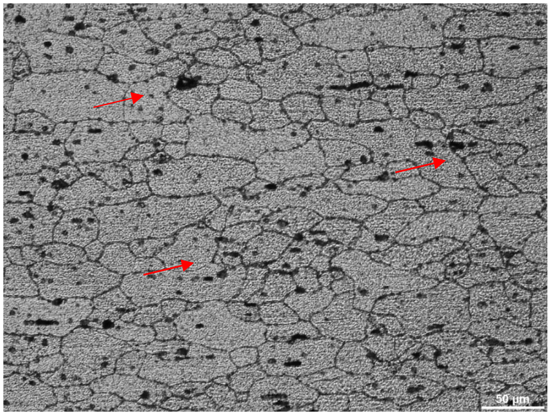
  • The cold-sprayed deposits displayed yield strengths similar to wrought peak-aged samples after exposure. Furthermore, the cold-sprayed deposits retained a higher percentage of tensile strength after 90 days exposure in samples pre-stressed to 25% and 65% of yield strength than the wrought counterparts did. The reduction in residual strength was attributed to the development of stress corrosion cracking and was supported by metallographic evidence, which revealed pitting and intergranular branch cracking in the wrought samples, with depths of attack averaging between 350 and 400 μm.
  • At the same stress conditions, the cold-sprayed deposits showed negligible evidence of corrosion. When samples were pre-stressed to 85% of the yield strength and exposed for 90 days, wrought and cold spray deposits retained a similar percentage of residual strength. Metallographic evidence showed average depths of attack reached 650 μm for the wrought material, with some evidence of corrosive attack observed for the cold spray deposits, although not intergranular.
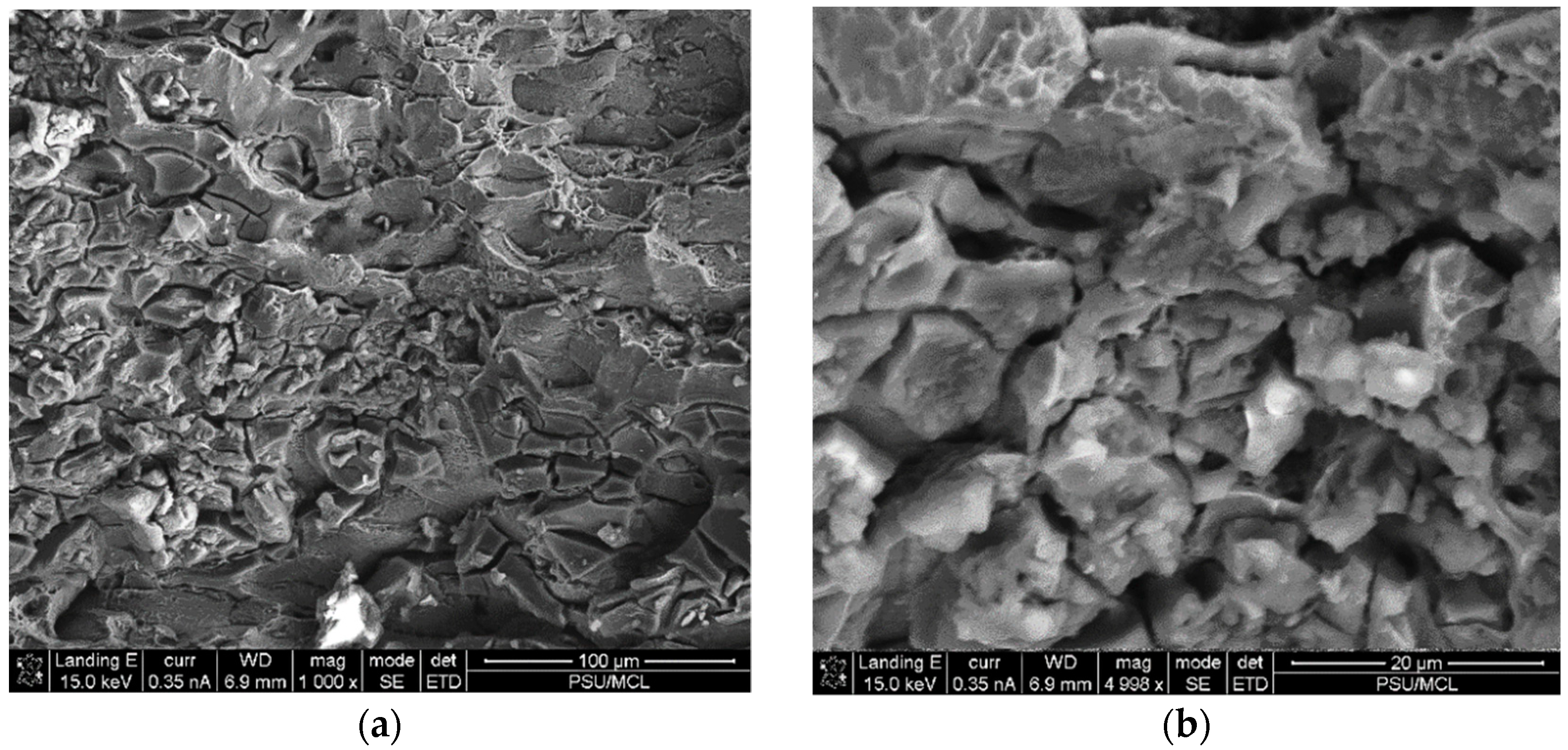
  • Scanning electron microscopy of the fractured wrought peak-aged Al 6061 showed failure from multiple mechanisms including cleavage, intergranular and transgranular fracture. Fractography of the cold-sprayed deposits revealed failure predominately by ductile dimple rupture, although brittle particle–particle fracture was also observed. Microstructural analysis supports that the wrought samples failed by stress corrosion cracking while the cold-sprayed samples failure predominately by mechanical means and general corrosion.
  • The dissimilarities between the SCC response of the differently processed materials is attributed to the benefits of the cold spray process, which includes maintaining fine grain structure of the feedstock powder, fine distribution of second phase precipitates, and low oxidation.

Author Contributions

Conceptualization, V.C. and T.E.; Methodology, V.C., J.S., M.S. and T.E.; Validation, M.S. and J.S.; Formal Analysis, M.S.; Investigation, J.S., M.S., T.E. and V.C.; Writing—Original Draft Preparation, Review and Editing, M.S.

Funding

This research received no external funding.

Conflicts of Interest

The authors declare no conflict of interest.

References

  1. Champagne, V.K. The Cold Spray Materials Deposition Process: Fundamentals and Applications, 1st ed.; Woodhead Publishing: Cambridge, UK, 2007. [Google Scholar]
  2. Schmidt, T.; Gartner, F.; Assadi, H.; Kreye, H. Development of a generalized parameter window for cold spray deposition. Acta Mater. 2006, 54, 729–742. [Google Scholar] [CrossRef]
  3. Assadi, H.; Gartner, F.; Stoltenhoff, T.; Kreye, H. Bonding mechanism in cold gas spraying. Acta Mater. 2003, 51, 4379–4394. [Google Scholar] [CrossRef]
  4. Zou, Y.; Goldbaum, D.; Szpunar, J.A.; Yue, S. Microstructure and nanohardness of cold-sprayed coatings: Electron backscattered diffraction and nanoindentation studies. Scr. Mater. 2010, 62, 395–398. [Google Scholar] [CrossRef]
  5. Lyle, J.P.; Cebulak, W.S. Powder metallurgy approach for control of microstructure and properties in high strength aluminum alloys. MTA 1975, 6, 685. [Google Scholar] [CrossRef]
  6. Pickens, J.R.; Christodoulou, L. The stress-corrosion cracking behavior of high-strength aluminum powder metallurgy alloys. MTA 1987, 18, 135–149. [Google Scholar] [CrossRef]
  7. Wang, S.D.; Xu, D.K.; Wang, B.J.; Sheng, L.Y.; Han, E.H.; Dong, C. Effect of Solution Treatment on Stress Corrosion Cracking Behavior of an As-Forged Mg-Zn-Y-Zr Alloy; Springer Nature: Basingstoke, UK, July 2016. [Google Scholar] [CrossRef]
  8. Williams, G.; ap Llwyd Dafydd, H.; Grace, R. The localised corrosion of Mg alloy AZ31 in chloride containing electrolyte studied by a scanning vibrating electrode technique. Electrochim. Acta 2013, 109, 489–501. [Google Scholar] [CrossRef]
  9. Lebouil, S.; Duboin, A.; Monti, F.; Tabeling, P.; Volovitch, P.; Ogle, K. A novel approach to on-line measurement of gas evolution kinetics: Application to the negative difference effect of Mg in chloride solution. Electrochim. Acta 2014, 124, 176–182. [Google Scholar] [CrossRef]
  10. Ralston, K.D.; Williams, G.; Birbilis, N. Effect of pH on the grain size dependence of magnesium corrosion. Corrosion 2012, 68, 507–517. [Google Scholar] [CrossRef]
  11. Winzer, N.; Atrens, A.; Song, G.; Ghali, E.; Dietzel, W.; Kainer, K.U.; Hort, N.; Blawert, C. A critical review of the stress corrosion cracking (SCC) of magnesium alloys. Adv. Eng. Mater. 2005, 7, 659–693. [Google Scholar] [CrossRef]
  12. Jafari, S.; Harandi, S.E.; Singh Raman, R.K. A Review of stress-corrosion cracking and corrosion fatigue of magnesium alloys for biodegradable implant applications. J. Mater. 2015, 67, 1143–1153. [Google Scholar] [CrossRef]
  13. Kannan, M.B.; Dietzel, W. Pitting-induced hydrogen embrittlement of magnesium-aluminium alloy. Mater. Des. 2012, 42, 321–326. [Google Scholar] [CrossRef]
  14. Deakin, J.; Dong, Z.H.; Lynch, B.; Newman, R.C. De-alloying of type 316 stainless steel in hot, concentrated sodium hydroxide solution. Corros. Sci. 2004, 46, 2117–2133. [Google Scholar] [CrossRef]
  15. Knight, S.P.; Birbilis, N.; Muddle, B.C.; Trueman, A.R.; Lynch, S.P. In situ X-ray tomography of intergranular corrosion of 2024 and 7050 aluminium alloys. Corros. Sci. 2010, 52, 3855–3860. [Google Scholar] [CrossRef]
  16. Raja, V.S.; Shoji, T. Stress Corrosion Cracking: Theory and Practice (Woodhead Publishing Series in Metals and Surface Engineering); Elsevier: Cambridge, UK, 2011. [Google Scholar]
  17. Renner, F.U.; Ankah, G.N.; Bashir, A.; Ma, D.; Biedermann, P.U.; Shrestha, B.R.; Nellessen, M.; Khorashadizadeh, A.; Losada-Pérez, P.; Duarte, M.J.; et al. Star-shaped crystallographic cracking of localized nanoporous defects. Adv. Mater. 2015, 27, 4877–4882. [Google Scholar] [CrossRef] [PubMed]
  18. Holroyd, N.J.H.; Vasudevan, A.K.; Christodoulou, L. Aluminum Alloys–Contemporary Research and Applications; Treatise on Materials Science and Technology; Academic Press: Boston, MA, USA, 1989; pp. 46–52. [Google Scholar]
  19. Holroyd, N.J.H. Environment-Induced Cracking of High-Strength Aluminum Alloys. In Proceedings of the First International Conference on Environmental Induced Cracking of Metals, Sheboygan, WI, USA, 2–7 October 1988; Gangloff, R.P., Ives, M.B., Eds.; National Association of Corrosion Engineers: Houston, TX, USA, 1990; pp. 311–345. [Google Scholar]
  20. Gruhl, W. Stress corrosion cracking of high strength aluminum alloys. Z. Metalkd. 1984, 75, 819–826. [Google Scholar]
  21. Burleigh, T.D. The postulated mechanisms for stress corrosion cracking of aluminum alloys: A review of the literature 1980–1989. Corrosion 1991, 47, 89–98. [Google Scholar] [CrossRef]
  22. Braun, R. Environmentally assisted cracking of aluminium alloys. Materialwiss. Werkstofftech. 2007, 38, 674–689. [Google Scholar] [CrossRef]
  23. Braun, R. On the stress corrosion cracking behaviour of 6XXX series aluminium alloys. Int. J. Mater. Res. 2010, 101, 657–668. [Google Scholar] [CrossRef]
  24. Rokni, M.R.; Widener, C.A.; Ozdemir, O.C.; Crawford, G.A. Microstructure and mechanical properties of cold sprayed 6061 Al in As-sprayed and heat treated condition. Surf. Coat. Tech. 2017, 309, 641–650. [Google Scholar] [CrossRef]
  25. Gärtner, F.; Stoltenhoff, T.; Voyer, J.; Kreye, H.; Riekehr, S.; Koçak, M. Mechanical properties of cold-sprayed and thermally sprayed copper coatings. Surf. Coat. Tech. 2006, 200, 6770–6782. [Google Scholar] [CrossRef]
  26. Meng, X.-M.; Zhang, J.-B.; Han, W.; Zhao, J.; Liang, Y.-L. Influence of annealing treatment on the microstructure and mechanical performance of cold sprayed 304 stainless steel coating. Appl. Surf. Sci. 2011, 258, 700–704. [Google Scholar] [CrossRef]
  27. AL-Mangour, B.; Vo, P.; Mongrain, R.; Irissou, E.; Yue, S. Effect of heat treatment on the microstructure and mechanical properties of stainless steel 316L coatings produced by cold spray for biomedical applications. J. Therm. Spray Technol. 2014, 23, 641–652. [Google Scholar] [CrossRef]
  28. ASTM E8-04, Standard Test Methods for Tension Testing of Metallic Materials; ASTM International: West Conshohocken, PA, USA, 2004.
  29. ASTM standard G64-99, Standard Classification of Resistance to Stress-Corrosion Cracking of Heat-Treatable Aluminum Alloys; ASTM International: West Conshohocken, PA, USA, 2013.
  30. ASTM B117-18, Standard Practice for Operating Salt Spray (Fog) Apparatus; ASTM International: West Conshohocken, PA, USA, 2018.
  31. ASTM-E112-12, Standard Test Methods for Determining Average Grain Size; ASTM International: West Conshohocken, PA, USA, 2013.
  32. Rokni, M.R.; Widener, C.A.; Champagne, V.K.; Crawford, G.A. Microstructure and mechanical properties of cold sprayed 7075 deposition during non-isothermal annealing. Surf. Coat. Tech. 2015, 276, 305–315. [Google Scholar] [CrossRef]
  33. Rokni, M.R.; Widener, C.A.; Nardi, A.T.; Champagne, V.K. Nano crystalline high energy milled 5083 Al powder deposited using cold spray. Appl. Surf. Sci. 2014, 305, 797–804. [Google Scholar] [CrossRef]
  34. Ajdelsztajn, L.; Schoenung, J.M.; Jodoin, B.; Kim, G.E. Cold spray deposition of nanocrystalline aluminum alloys. Metall. Mater. Trans. A 2005, 36, 657–666. [Google Scholar] [CrossRef]
  35. Rokni, M.R.; Widener, C.A.; Champagne, V.R. Microstructural stability of ultrafine grained cold sprayed 6061 aluminum alloy. Appl. Surf. Sci. 2014, 290, 482–489. [Google Scholar] [CrossRef]
  36. Rokni, M.R.; Widener, C.A.; Crawford, G.A. Microstructural evolution of 7075 Al gas atomized powder and high-pressure cold sprayed deposition. Surf. Coat. Tech. 2014, 251, 254–263. [Google Scholar] [CrossRef]
  37. Rokni, M.R.; Widener, C.A.; Champagne, V.K. Microstructural evolution of 6061 aluminum gas-atomized powder and high-pressure cold-sprayed deposition. J. Therm. Spray Tech. 2014, 23, 514–524. [Google Scholar] [CrossRef]
  38. Zou, Y.; Qin, W.; Irissou, E.; Legoux, J.-G.; Yue, S.; Szpunar, A.J. Dynamic recrystallization in the particle/particle interfacial region of cold-sprayed nickel coating: Electron backscatter diffraction characterization. Scripta Mater. 2009, 61, 899–902. [Google Scholar] [CrossRef]
  39. Borchers, C.; Gärtner, F.; Stoltenhoff, T.; Kreye, H. Formation of persistent dislocation loops by ultra-high strain-rate deformation during cold spraying. Acta Mater. 2005, 53, 2991–3000. [Google Scholar] [CrossRef]
  40. Kim, K.H.; Watanabe, M.; Kawakita, J.; Kuroda, S. Grain refinement in single titanium powder particle impacted at high velocity. Scripta Mater. 2008, 59, 768–771. [Google Scholar] [CrossRef]
  41. Henao, J.; Sharma, M.M. Characterization, deposition mechanisms and modeling of metallic glass powders for cold spray. In Cold-Spray Coatings: Recent Trends and Future Perspectives; Cavaliere, P., Ed.; Springer: Berlin, Germany, 2017; pp. 251–272. [Google Scholar]
  42. Sharma, M.M.; Eden, T.J.; Golesich, B.T. Effect of surface preparation on the microstructure, adhesion and tensile properties of cold sprayed aluminum coatings on AA2024 substrates. J. Therm. Spray. Tech. 2015, 24, 410–422. [Google Scholar] [CrossRef]
  43. Farshidi, M.H.; Kazeminezhad, M.; Miyamoto, H. Severe plastic deformation of 6061 aluminum alloy tube with pre and post heat treatments. Mater. Sci. Eng. A 2013, 563, 60–67. [Google Scholar] [CrossRef]
  44. Kim, W.J.; Kim, J.K.; Park, T.Y.; Hong, S.I.; Kim, D.I.; Kim, Y.S.; Lee, J.D. Enhancement of strength and superplasticity in a 6061 Al alloy processed by equal-channel-angular-pressing. Metall. Mater. Trans. A 2002, 33, 3155–3164. [Google Scholar] [CrossRef]
  45. Nurislamova, G.; Sauvage, X.; Murashkin, M.; Islamgaliev, R.; Valiev, R. Nanostructure and related mechanical properties of an Al–Mg–Si alloy processed by severe plastic deformation. Philos. Mag. Lett. 2008, 88, 459–466. [Google Scholar] [CrossRef]
  46. Liu, X.; Frankel, G.S.; Zoofan, B.; Rokhlin, S.I. In-situ observation of intergranular stress corrosion cracking in AA2024-T3 under constant load conditions. Corros. Sci. 2007, 49, 139–148. [Google Scholar] [CrossRef] [Green Version]
  47. Phull, B. Evaluating stress-corrosion cracking. In ASM Handbook Corrosion: Fundamentals, Testing, and Protection; ASM International: Russell Township, OH, USA, 2003; pp. 42–44. [Google Scholar]
  48. Speidel, M.O. Stress corrosion cracking of aluminum alloys. Metall. Trans. A 1975, 6, 631–651. [Google Scholar] [CrossRef]
  49. Huang, I.-W.; Hurley, B.L.; Yang, F.; Buhheit, R.G. Dependence on temperature, pH, and Cl in the uniform corrosion of aluminum alloys 2024-T3, 6061-T6, and 7075-T6. Electrochim. Acta 2016, 199, 242–253. [Google Scholar] [CrossRef]
Figure 1. Al 6061 as-received powder at (a) low magnification and (b) high magnification; particles primarily exhibit a spherical morphology.
Coatings 09 00445 g001
Figure 2. Particle size distribution (PSD) for the Al 6061 feedstock powder.
Coatings 09 00445 g002
Figure 3. Cross section and isometric rendering of cold-sprayed coating on Al 6061-T6 plate.
Coatings 09 00445 g003
Figure 4. Corrosion-resistant uniaxial test fixture designed at PSU/ARL, used in SCC testing loaded with a sample (a) before coating to prevent galvanic couple and (b) after coating with STOP-OFF lacquer.
Coatings 09 00445 g004
Figure 5. Fiber Bragg grating data captured during fixture testing. Units on the vertical axis are in microstrain, and the horizontal axis is time.
Coatings 09 00445 g005
Figure 6. Optical cross-sectional micrograph for cold spray Al 6061, etched using Keller’s reagent, showing the particle morphologies after deposition. (a) There is some evidence of interparticle voids and porosity, as indicated by arrows and (b) high-magnification micrograph showing small average grain size and finer sub grains resulting from buildup of particles.
Coatings 09 00445 g006aCoatings 09 00445 g006b
Figure 7. Optical cross-sectional micrograph of wrought Al 6061-T6 samples in as-received condition and etched using Keller’s reagent. There is clear evidence of randomly sized and irregularly distributed second-phase precipitates.
Coatings 09 00445 g007
Figure 8. Stress/strain behavior of the wrought Al 6061-T6 samples after 90 days of B-117 salt fog exposure.
Coatings 09 00445 g008
Figure 9. Stress/strain behavior of the cold-sprayed Al 6061-T6 deposits after 90 days of B-117 salt fog exposure.
Coatings 09 00445 g009
Figure 10. Tensile data for wrought (W) and cold-sprayed (CS) samples at various pre-stress levels after 90 days of B-117 salt fog exposure (SS).
Coatings 09 00445 g010
Figure 11. Strain at fracture and strength retained of wrought (W) and cold-sprayed (CS) samples at various pre-stress levels after 90 days of B-117 salt fog exposure (SF).
Coatings 09 00445 g011
Figure 12. Metallographic section of wrought Al 6061-T6 stressed at 25% of yield strength after 90 days exposure to B117 salt fog testing. Various locations show pitting and intergranular crack branching.
Coatings 09 00445 g012
Figure 13. Metallographic section of wrought Al 6061-T6 stressed at 65% of yield strength after 90 days exposure to B117 salt fog testing. Various locations show pitting and intergranular crack branching.
Coatings 09 00445 g013
Figure 14. Metallographic section of wrought Al 6061-T6 stressed at 85% of yield strength after 90 days exposure to B117 salt fog testing. Various locations show pitting and intergranular crack branching.
Coatings 09 00445 g014
Figure 15. Metallographic sections of cold spray samples at (a) 25% yield strength and (b) 65% yield strength after 90 days exposure to B117 salt fog testing. There is no indication of stress corrosion cracking through branching or evidence of any other artifacts related to corrosive attack on failed sample cross sections; (c) Metallographic sections of cold spray samples at 85% yield strength after 90 days exposure to B117 salt fog testing. There is no indication of stress corrosion cracking through branching on the entire cross section. Evidence of slight corrosive attack is observed and identified on the figure.
Coatings 09 00445 g015
Figure 16. Secondary electron images of wrought Al 6061-T6 fracture surfaces. The fractography predominately shows (a) cleavage as well as intergranular fracture with (b) the grain boundaries attacked in the 25% yield stress condition.
Coatings 09 00445 g016
Figure 17. Secondary electron images of wrought Al 6061-T6 fracture surfaces. The fractography predominately shows cleavage and transgranular fracture (circles), but intergranular facture is also present (arrows) in (a) 65% and (b) 85% stress conditions.
Coatings 09 00445 g017
Figure 18. Secondary electron images of cold-sprayed Al 6061 fracture surfaces. The fractography predominately shows the failure mode to be ductile in nature in (a) 25% stress, (b) 65% stress, and (c) 85% stress conditions. Smooth particle–particle fracture can be observed (arrows).
Coatings 09 00445 g018
Figure 19. EDS analysis of wrought fracture surface after B117 testing, showing evidence of second-phase particle concentrations of Mg, Si and Fe.
Coatings 09 00445 g019
Figure 20. EDS analysis of cold-sprayed, stressed 25% fracture surface after B117 testing, showing the fracture surface is predominately free of precipitates or element segregation. Two second-phase particles are obvious, one an oxide inclusion and the other rich in Si.
Coatings 09 00445 g020
Table 1. Cold spray processing parameters for Al 6061 bulk deposit.
ContentsParametersValue
Feedstock PowderPowder InformationAl6061 Valimet (−270/+635 mesh)
Cold Spray NozzleNozzle TypePBI (polybenzimidazole) Celazole®
Throat Diameter2 mm
Exit Diameter4 mm
Length120 mm
Gas, Powder and Robot ControlsGas Type Helium
Gas Pressure25 bar
Gas Heater400 C
Mass Feed Rate4.8 grams per minute
Robot ProgramRaster
Standoff1 inch
Raster Speed200 mm/sec
Table 2. Standard test parameters for B-117 testing.
Salt ConcentrationSalt Solution pHSalt Solution TemperatureExposure Zone Temperature
4%–6%6.5–7.235 °C35 ± 2 °C

