Article

Prospects of Low-Pressure Cold Spray for Superhydrophobic Coatings

1
Department of Mechanics, Materials Science and Engineering, Wroclaw University of Science and Technology, 25 Smoluchowskiego St., Pl-50370 Wroclaw, Poland
2
Department of Materials Science, Strength and Welding Technology, Wroclaw University of Science and Technology, 5 Łukasiewicza St., Pl-50371 Wroclaw, Poland
*
Author to whom correspondence should be addressed.
Coatings 2019, 9(12), 829; https://doi.org/10.3390/coatings9120829
Submission received: 28 October 2019 / Revised: 20 November 2019 / Accepted: 3 December 2019 / Published: 5 December 2019
(This article belongs to the Special Issue Cold Spraying: Recent Trends and Future Views)

Abstract

:
A major challenge in materials engineering is the development of new materials and methods and/or novel combination of existing ones, all fostering innovation. For that reason, this study aims at the synergy between low-pressure cold spray (LPCS) as a tool for coating deposition and sol-gel technique for fabrication of the feedstock powder. The complementarity of both methods is important for the examined topic. On one side, the LPCS being automized and quick mean provides the solid-state of feedstock material in nondestructive conditions and hence the hydrophobicity imparted on the sol-gel route is preserved. On the other side, the sol-gel synthesis enables the production of oxide materials with enhanced deformability due to amorphous form which supports the anchoring while LPCS spraying. In the paper, several aspects including optimal fluoroalkylsilane (FOTS) concentration or substrate roughness are examined initially for altering the superhydrophobicity of produced coatings. Further, it is shown that the appropriate optimization of feedstock powder, being submicron silica matrices covered with two-layer FOTS sheath, may facilitate the anchoring process, support roughening the substrate or cause enhancement the coating hydrophobicity. All the discussion is supported by the characteristics including surface morphology, wettability and thermal behaviour examined by electron microscopy, water contact angle measurements and thermal analysis (TGA/DSC), respectively. The coatings presented in the paper are characterized by an uneven thickness of up to a few silica particles, but final hydrophobicity is provided uniformly on the surface by the formation of multi-level roughness by a detachment of outer layer from the SiO2 particles. Thus, the presented approach constitutes a simple and fast solution for the fabrication of functionalized coatings using LPCS including industrial potential and fundamental research character.

Graphical Abstract

1. Introduction

Innovation practice contributes to global activity in science and industry by the development of new engineering solutions and altering the already existing ones. In this aspect, the fairly new cold spray technique [1], 2001, accounts its extreme popularity for the relative simplicity of the concept and optional automation which can be successfully utilized for adapting to new materials and methods.
Starting with methods, typical cold spray (CS) systems are low-pressure cold spray (LPCS) and high-pressure cold spray (HPCS) which differ in generated pressures and velocities [2,3]. Distinct spraying variants, such as vacuum cold spray (VCS) whether pulsed gas dynamic spray (PGDS), may differ in construction of nozzle, powder injection system, gas and protective atmosphere applied, heating capabilities and position of the heater, portability level, presence of additional systems for limiting the wear of nozzle or proper agglomeration assistance [2,3,4]. What all of them have in common is lacking in feedstock material melting [1,2,3,4,5], which is unique among other thermal spraying technologies. New variations of CS technique are introduced in order to expand the range of feedstock materials and substrates [2,3,4] and thus the range of applications. Alongside this, the deposition sequence for composite coatings is often being discussed [6] and more and more frequently mathematical models are prepared to assist experimental data [7,8,9,10]. All these activities are aimed at the development of cold spray. This great potential of CS is well illustrated on the example of the LPCS, employed in the paper, which was initially invented to produce coatings made of metals with low melting point and low mechanical strength (e.g., zinc, aluminium, copper) [1,2,3]. As the method developed, higher-strength metals and alloys were also deposited basing on the crystal grain refinement. Then, polymer coatings were formed due to application of lower velocities (about 100 m·s−1) and finally, even ceramic materials were employed [11,12,13,14,15] which was possible due to particle fragmentation and particle interlocking. However, attempts to deposit conventional (hard and brittle) ceramics are still not common which is mainly caused by the lack of understanding of the bonding mechanism nature.
An overview of the literature indicates the application of ceramic materials to be tempting due to the completely different features offered when compared to metals [2,3,4]. It is enough to name the aerospace industry and gas turbine market where low density, good corrosion resistance, and high strength at high temperatures are undoubtedly the main advantages of ceramic materials. In this context, the prospect of using the LPCS method for functional ceramics coatings spraying is even more attractive due to a number of unique properties of metal oxides including semiconducting, magnetic, electric, catalytic, or biological [15,16]. Functional coatings can interact with a number of specific chemical stimuli such as the presence of water, or physical stimuli such as temperature, magnetic field, or light. A distinct feature of the metal oxides is the strong dependence of their properties on crystal structure and stoichiometry and therefore the low-pressure cold spray method seems to be particularly predisposed to the production of such coatings [2,3]. The LPCS minimizing the heat input can preserve or guarantee the desired materials behaviour. For this reason, the purpose of this article is to join the promising trend of increasing the potential of the LPCS method by demonstrating the ability to spray functional oxide coating. The coating described in the paper exhibits superhydrophobic properties, so its applications go far beyond the conventional range of applications of the cold-spray method. At the same time, this increases the range of methods used for superhydrophobic coatings production.
Superhydrophobic surfaces (SHS) are actively studied across a wide range of applications and industries. As a rule, with the unique water-repelling feature of these surfaces, their use is associated with the ability to reduce wear of metal surfaces due to corrosion in the aquatic environment [16,17,18,19]. Superhydrophobic surfaces can minimize the interaction between metal substrates and corrosive substances and provide better anti-corrosion properties by reduction of contact time with water [16,17,18,20,21]. Often it facilitates self-cleaning potential taking advantage of low water adhesion [16,18,19,22,23,24]. Recent studies in biomedicine demonstrate that also the adhesion of medias containing blood, cells, or protein is hampered for SHS, which prevent their adsorption due to air entrapping on the solid-liquid interference. This air layer decreases the total area available for protein binding and as a result, such materials can be used for biofouling-colonization of submerged surfaces by microorganisms such as bacteria. In such a manner, bacterial growth on SHS can be inhibited and control cell proliferation is possible [25]. Additionally, the differences in wettability of materials can be employed for “Lab-on-a-Chip” medical diagnostics to promote selective deposition of molecules or cells or the movement of fluid from one area to another [26,27,28,29]. All these biomedical applications are considered to be the most promising for superhydrophobic materials.
Numerous applications of SHS leads to a wide variety of methods for their production, among which, according to the authors’ knowledge, the LPCS technique is missing until now. In this work, great emphasis is put on the appropriate optimization of the feedstock powder to face the challenge [30,31]. In the majority of papers devoted to spraying ceramic materials [5,15,32,33,34,35,36,37,38], the agglomeration of the feedstock powder was recognized as the factor of utmost importance for successful ceramic coating formation. It was also reported that not only the size but also the bonding character of individual agglomerates is significant for proper anchoring to the substrate. In case of high-temperature pre-treatment of feedstock powder typically applied for ceramics, such as sintering, the binding of separate particles chemically and physically is observed. However, it is chemical diffusion which plays the predominant role which finally leads to solid-state neck formation characterized by high binding energy [2,13]. For soft non-sintered agglomerates, the binding energy of individual particles is much lower because the particles are joined by purely physical interactions [39], for instance through a suitable liquid binder. The weak liquid-bridge forces liable for the creation of soft agglomerates assist easy fracture upon the impact. Therefore, it is believed that only so-called soft agglomerates are preferred to be sprayed using the LPCS method [40,41]. Soft agglomerates network can be achieved either by adding a suitable binder to the powder [30,32,35] or by using a fresh sol-gel powder [13]. It has been shown very recently that organic liquid substances remained after the sol-gel synthesis act as binders responsible and sufficient for agglomeration [13]. However, the properties of as-prepared coatings are considered rather low post-treatment including heat or mechanical treatment are suggested [11,15,42,43]. The possibility of a potential repair may be also advantageous [42,43,44,45]. However, it is worth emphasizing that in the case of superhydrophobic coating analyzed in this work, mechanical strength does not dominate over its functionality.
Driven by the concept to ensure high functionality and considering that only soft agglomerates are preferred to be deposited using the LPCS method [13], the use of the sol-gel method to optimize feedstock powder seems to be an obvious solution. First of all, the functionality of feedstock powder may be easily achieved on the sol-gel route, because carefully planned synthesis may provide the set of new, programmable features. Unlike the utilization of ready-made powders with properties ensured by the manufacturer, simple SiO2-chemistry design [21,30,39,46,47,48,49,50,51,52] enables for adding functionalities with hydrophobicity as a leading example in this paper. Secondly, the hydrophobic surface must have two important parameters: adequate roughness and low free surface energy [6]. In order to ensure the appropriate roughness, the easiest way is to change the morphology of the substrate, but such solution (e.g., etching) is not always feasible and often brings the inherent risk of substrate damage [53]. In this work, it was decided to obtain the desired roughness profile by adjusting the shape and size of cold sprayed particles [49,54,55,56,57,58,59]. Low surface energy was ensured by appropriate chemical functionalization of these particles [30,50,60]. All these important powder parameters, i.e., required size, shape, and functionality of particles were achieved thanks to the adaptation of the sol-gel method for the feedstock powder production. Sol-gel SiO2 matrices utilized in this work offer significant change of surface roughness while maintaining low toxicity, chemical inertness, controllable size, thermal and environmental stability, optical transparency, and biocompatibility. The high hydrophobic potential was ensured on the sol-gel route by utilization of fluoroalkylsilane (FOTS) functionalizing agent for modification of SiO2 feedstock powder [22,30,52]. This paper shows that the conditions of spraying minimizing the heat input do not cause the decomposition of FOTS and as a result, they allow the desired materials behaviour to be preserved.
The approach presented in this work not only extends the range of materials used so far for LPCS spraying but it also changes the purpose of the powder itself. For the first time, the powder is not only used for desired coating production, but it also allows for obtaining the appropriate surface roughness necessary to maintain functionality. Moreover, this roughness is obtained not only by former substrate roughness and powder particles deposited on the substrate but also by particles reflected from the substrate surface, leaving submicron dents and forming multi-level roughness. Great importance for further development of LPCS technology can also be seen in a new approach to the thickness of the cold-spray coating. This work shows that LPCS may be used for obtaining thin coatings (of submicron thickness), which despite relatively low thickness provide the continuity of the functionality.

2. Materials and Methods

2.1. Powders Synthesis

The fluorinated silica spheres were prepared using the one-pot method in a similar manner as described by Jasiorski et al. [61]. The first step involved receiving a colloidal suspension of the silica particles which were acquired by the Stöber method basing on hydrolysis and condensation of 3.1 mL of tetraethoxysilane (TEOS, Si(OC2H5)4, 98%, Alfa Aesar, Haverhill, MA, USA) in a mixture with 42 mL of ethanol (C2H5OH, 96%, Avantor Performance Materials Poland S.A., Gliwice, Poland) and distilled water. Aqueous ammonia solution (NH3(aq), 25%, Avantor Performance Materials Poland S.A.) was used as a catalyst to initiate the reaction. The solution was mixed using a magnetic stirrer for 2 h at room temperature. In the second step, 0.15 mL of triethoxy(1H,1H,2H,2H-perfluoro-1-octyl)silane (FOTS, C14H19F13O3Si, 98%, Sigma Aldrich Sp. z o.o., Poznan, Poland) was added to the solution and stirring was continued for a further 1 h. Then as-prepared particles were dried at room temperature to finally obtain a white powder, denoted SiO2–F. The simplified scheme of the synthesis is provided in Supplementary Materials (Figure S1).
Remark: It is worth of emphasizing that at first the series of powders containing the FOTS in volumes 0.00 and 0.10 to 0.30 mL (differing by 0.05) was prepared to investigate the influence on the final hydrophobicity of coatings. The powder containing 0.15 mL of FOTS was chosen for further evaluation. The effect of the increasing volume of functionalizing reagent FOTS on the hydrophobicity of the coatings was shown in Supplementary Materials (Figure S2).

2.2. Substrates Preparation and Spraying Parameters

Substrate materials were plates of aluminium alloy AA1350 (99.5%) with dimensions of 20 mm × 20 mm × 7 mm. The substrates surface was activated by sandblasting under a pressure of 0.6 MPa using alumina sand-Al2O3 particles of irregular (crashed) shape and size of 350 μm.
The coatings were then sprayed using DYMET 413 (Obninsk Center for Powder Spraying, Obninsk, Russia). Air with a pressure of 0.5 MPa and a temperature of 600 °C was used as a working gas. Spray distance was set to 10 mm and manipulator traverse speed to 5 mm/s.

2.3. Characterization Methods

The morphology, microstructure, and elemental composition of powders and coatings were analysed using scanning electron microscopy (S-3400 N, Hitachi, Tokyo, Japan) and ultra-high resolution field-emission scanning electron microscopy (FESEM, Nova NanoSEM 230, FEI, Hillsboro, OR, USA) both equipped with energy-dispersive X-ray spectroscopy (EDX) detectors. The examination of individual particles of feedstock powder was possible using high-resolution transmission electron microscopy (CM-20 SuperTwin, Philips, Amsterdam, The Netherlands). The particle size distribution histogram was determined using ImageJ software (version 1.52r) on the basis of SEM pictures.
Thermogravimetric analysis and differential scanning calorimetry (DSC/TGA STA 449 F1 Jupiter instrument, Netzsch, Selb, Germany) were performed on the SiO2–F feedstock powder at a heating rate of 5 K·min−1.
Contact angle measurements were carried out with a droplet volume of about 2 μL to minimize the gravitational effects using a goniometer (Surftens Universal, OEG GmbH, Frankfurt (Oder), Germany) with manual dosing unit and angle precision of ±0.5° in the indoor conditions. The static contact angle values were measured at least six times and the averaged value for three samples each time is reported.
The durability of the coating was examined by a series of tests verifying thermal, chemical and abrasion resistance. Initially, the wettability of as-prepared coatings was measured and after each separate test, it was repeated for comparison (change in contact angle (CA) is reported). The high-temperature test included two-hours annealing at different temperatures varying from 50 to 500 °C and quenching in air. Each time a new sample was heat-treated, as shown in [57,58]. Chemical stability covered static and dynamic tests, being immersion in water and absolute alcohol like presented in [38,57,58], and ultrasonic bath in absolute alcohol to simulate a harsher environment as in [38], respectively. Each continuous soaking of samples (90 h of immersion or 100 min in an ultrasonic bath) was interrupted only for short periods of drying and taking readings. Finally, manually operated abrasive wear measurements were conducted similarly to [16,51,62] by sliding sample surface on the surface of 800-grit sandpaper. The specimen, under exerted gravitational pressure 2.4 kPa (taking into account the 100 g weight and the surface size being 20 mm × 20 mm), was slid in 150 mm cycles followed always by 90-degree turn. Each sample was slid 5.55 m in total.

3. Results and Discussion

3.1. Selection of Functionalizing Reagent (FOTS) Content

The feedstock powder was produced in a single two-step process including SiO2 formation via Stöber technique and surface functionalization by adding fluorinated groups (FOTS). Six varieties of silicate powders with different fluoroalkylsilane content (FOTS 0.00, 0.10, 0.15, 0.20, 0.25, 0.30 mL) were produced that way and all were then deposited on aluminium substrates. Subsequently, the effect of the increasing volume of functionalizing reagent FOTS on the hydrophobicity of the coatings was investigated (Figure S2). The coating produced with unmodified silica powder is characterized by the low CA equal 23.0°, while the utilisation of modified powder provides imparting of hydrophobic properties resulting the CA increase more than 6.5 times. For the investigated amounts of FOTS, the obtained CA are from the range of 149° and 154°. Similar saturation of CA was observed by Wu et al. [51]. In this paper, the excess of the functionalized agent may facilitate filling the cavities for air entrapping what lead to loosing of the complex internal structure and hence CA decreases slightly. For that reason, based on contact angle measurements of as-prepared coatings the SiO2 modified with 0.15 mL FOTS coating which gave the highest CA 153.7° was chosen for further evaluation.

3.2. Characterization of Feedstock Powders

As innovation is important for development, the presented approach involves indigenous production of feedstock powder. The initial study of the successfully synthesized SiO2–F spheres conducted using Scanning Electron Microscopy (Figure 1a) reveals the powder in the form of similar monodispersed particles. This powder form and the degree of dispersity originates from the application of base catalyst, ammonia [49,50] while the repeatable architecture of cauliflower-like sheathed SiO2–F particles-the individual steps of synthesis. The macroscopic analysis ensured that the FOTS-covered SiO2 spheres (Figure 1a,b) are characterized by the high level of size and shape uniformity in submicron scale which is typical for sol-gel synthesized products [21,39,46,47,48,49,50,51]. Furthermore, the size distribution analysis (Figure 1c) illustrates average SiO2–F spheres diameter of 670 nm with the shape deviation ±50 nm which is rather common for silica formed in the Stöber process [22,47,48,59].
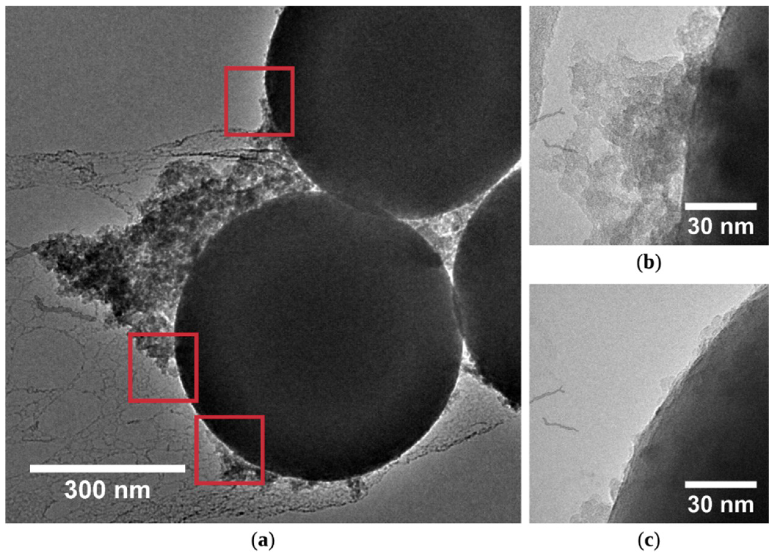
The structure of individual SiO2 spheres, as well as the cauliflower sheaths, were examined precisely using transmission electron microscopy. TEM pictures (Figure 2) present dense silica cores with an average diameter of about 500 ± 50 nm covered with low-density cloud-like structures, equivalent to the cauliflower-like sheaths observed by SEM imaging, increasing the SiO2–F diameter even about 300 nm. It may appear that these structures are similar to by-products of SiO2 synthesis in the environment of low ammonia content (catalyst) [61] but, in the presented paper, the proportion of substrates and catalyst to synthesize SiO2 powder was determined using the efficient idea with optimal ammonia content [61] which according to engineering practice ensures maximum efficiency of the process. Therefore, it can be concluded that the cauliflower-like sheaths on the surface on the silica spheres with the thickness ranging from few to few hundreds of nanometers (Figure 2) were formed while the second stage of synthesis, functionalization.
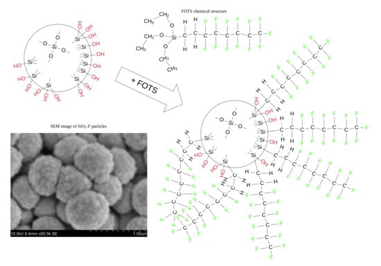
The course of the functionalization is illustrated in the Supplementary Materials (Figure S1). The scheme starts with the picture of silica core formed during the first stage of the synthesis, during which the TEOS hydrolysis proceeds to form physically and chemically active silanol groups (≡Si–OH) and simultaneously some of these silanol groups are utilized in condensation (polymerization) for creation of oxygen bridge network (≡Si–O–Si≡) that form the intrinsic structure of silica spheres [49,50]. Since the condensation never fully completes at the end of the synthesis the silica spheres still incorporate the number of residual silanol groups (≡Si–OH) within the volume and on its surface [63,64]. It is these active spots which are then successfully employed during the second stage of synthesis–functionalization [30,50] for joining long fluorocarbon chains acquired from a functionalizing reagent FOTS. Although it is worth noting that the sheath is composed of the outer and inner part. The outer sheath is built of cloud-like structures of submicron scale (Figure 2a,b) and inner sheath-nanolayers shielding the entire surface area of individual particles (Figure 2b,c). It is clearly visible that often cloud-type FOTS structures connect with nanoshells of FOTS on the surface of SiO2 (red-framed squares in Figure 2a,b) and hence the clear boundary between both kinds of the sheath is not easily recognizable. Nevertheless, at this level of magnification one can observe that nanolayers always cover the whole surface area of silica spheres while cloud-type FOTS structures occur rather randomly.
The difference in the type of FOTS sheath originates from the chemistry of the functionalization on the sol-gel route (Figure S1) because the incorporated long fluorocarbon chains, oriented outwardly with respect to the silica cores, are bonded covalently to the silica particles (replacing –OH groups) [38,51,65] they form the inner sheath. Subsequently, the sphericity of silica particles and the chained structure of FOTS form a steric barrier, which means that three-dimensionality of FOTS chains hinder binding of other fluorocarbon groups by shielding the active sites (–OH groups) on the silica surface [30]. For that reason, full saturation with FOTS chains is never possible and consequently functionalized SiO2 spheres contain always some amount of sterically blocked –OH groups on the surface. At the same time, there is still some portion of FOTS not chemically bonded to SiO2–F particles which are subjected to hydrolysis. Since the availability of the active spot on silica is limited, the autocondensation of FOTS chains is observed and the outer sheath is formed. Finally, due to chemical structure of FOTS, physical interaction between adjacent fluorocarbon chains of the FOTS, either belonging to the outer or inner sheath, causes their entangling into tridimensional complex structures [40,41] and hence FOTS sheaths are widespread across the whole investigated sample (Figure 1 and Figure 2).
It is well-known that the sol-gel process provides a high level of final product uniformity, but the instantaneous local volatility is always noticeable. This is one of the reasons why the sheath thickness varies within the single particle (Figure 1 and Figure 2). These variations are caused by the FOTS addition. As shown in the initial research (Figure S2) the increasing volume of functionalizing reagent FOTS added to the synthesis only to a certain extent increases hydrophobicity [30,52]. Above the certain optimal volume of FOTS, the contact angle decreases. Nevertheless, the optimum volume 0.15 F is used in the paper which surely include a small reserve of coupling agent. This slight excess forms subsequently cauliflower-like sheath covering the silica particles which not only can prevent the local FOTS shortage but also can be utilized for the advantage of hydrophobicity. Since no heat-treatment or chemical cleaning is applied, cloud-type FOTS structures are still present in the as-synthesized powder. For that reason, the received EDX maps (Figure 3) present the homogenous distribution of fluorine over the entire tested area (Figure 3b) while the silicon and oxygen readings are clearly associated with the presence of SiO2 spheres (Figure 3c). In such a manner it is confirmed that long fluorocarbon chains, represented on the maps as fluorine atoms, are constituents of both sheaths’ types—FOTS chains bonded chemically with SiO2 cores and physically attached cloud-type FOTS structures.
The single silica particle without adjacent residue cloud was tested to confirm additionally the grafting of FOTS directly to the surface area of silica spheres. The distribution of elements was examined using the line scanning profile of a single particle. The measured profile, indicated as a white line (Figure 4a), shows a single silica sphere containing Si, O, and F (Figure 4b). All elements are located between 810 and 1530 nm of the measured section which indicates the presence of SiO2–F sphere with approximate 720 nm diameter. One can notice, that the backgrounds of all tested elements are raised at the whole measured range which is probably associated with the presence of adjacent spheres behind the test subject.
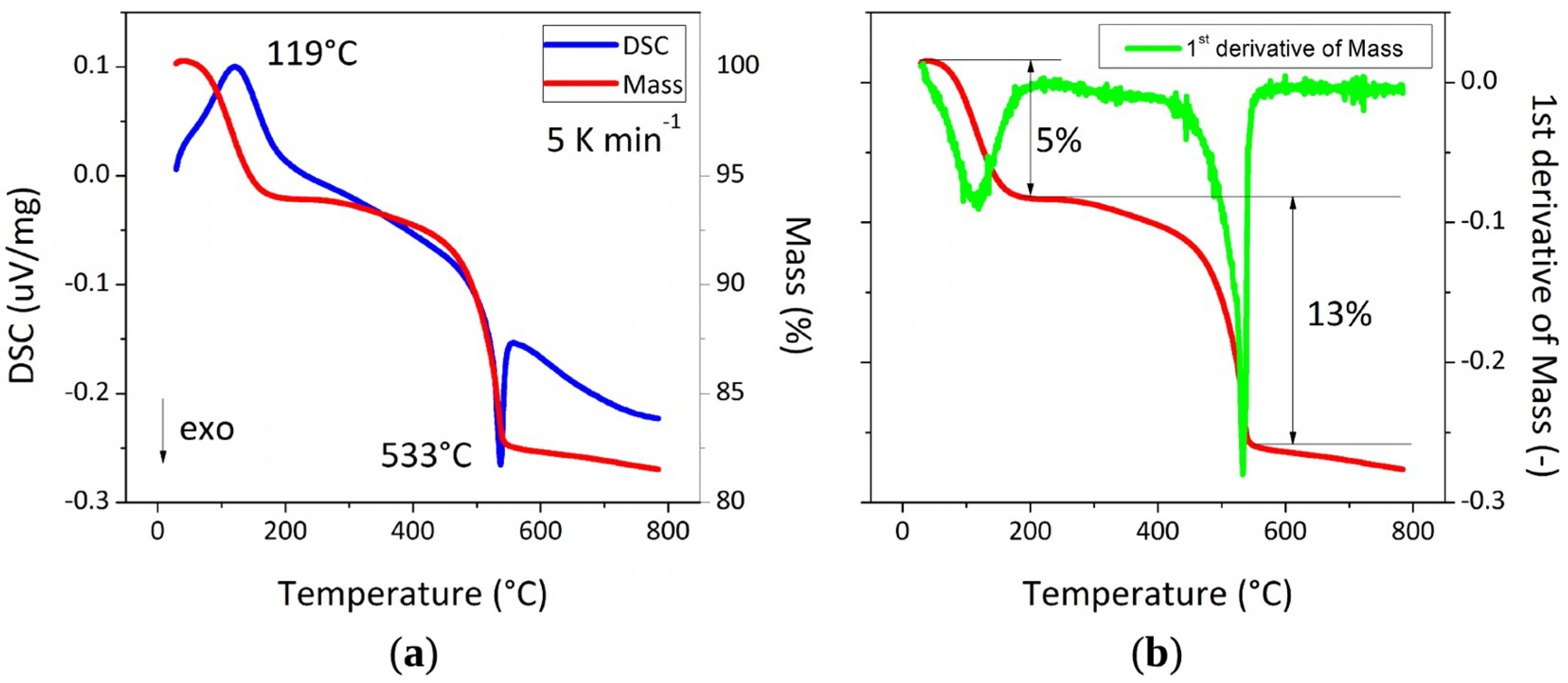
As the morphology of the functionalized silica spheres has been already discussed in detail the second crucial issue for LPCS feedstock powder needs to be investigated subsequently. Since LPCS deposition is strongly connected with changing the energy of individual particles and agglomerates the material in feed should endure the conditions of spraying and, more importantly, the formed coating should withstand the working conditions at elevated temperatures. Thus, the thermal behaviour of SiO2–F powder was tested with TG/DSC at temperatures ranging from room temperature to 800 °C (Figure 5). The slow heating rate 5 K·min−1 was chosen according to [64] in order to observe similar silica behaviour. The TG curve clearly reveals the weight loss proceeding in three stages distinguished by broad endothermic peak and sharp exothermic one demonstrated at DSC curve. The initial weight loss about 5% centred with the endothermic peak at 119 °C can be ascribed to dehydration which is simultaneous removal of physisorbed water, ammonia, and alcohol from the surface of SiO2–F spheres. Then, from about 180 °C dihydroxylation due to condensation of the hydroxyl groups (–OH) proceeds up to 560 ± 10 °C. Kim et al., and Ek et al. show [63,64] that at temperatures ranging from 150–550 °C the mass reduction of unmodified silica proceeds rather slowly consumes a similar mass percentage to dehydration. In contrast, the TG curve measured for SiO2–F powder (Figure 5) results in an almost 13% mass drop for this temperature range. For that reason, it can be concluded that this significant weight reduction is associated with not only water removal [63,64] but additionally with a decomposition of the fluorocarbon chains coming from functionalizing agent [59]. This decomposition takes place between 450 and 550 °C (Figure 5). Additionally, the threshold temperature of 533 °C is accompanied by an exothermic DSC peak. At the end of the heating process, above ~560 °C, the isolated hydroxyl groups are gradually removed which results in negligible mass loss of about 2% wt. This weight stabilization is also typical for unmodified silica particles [59,63,64].

3.3. Characterization of Coatings

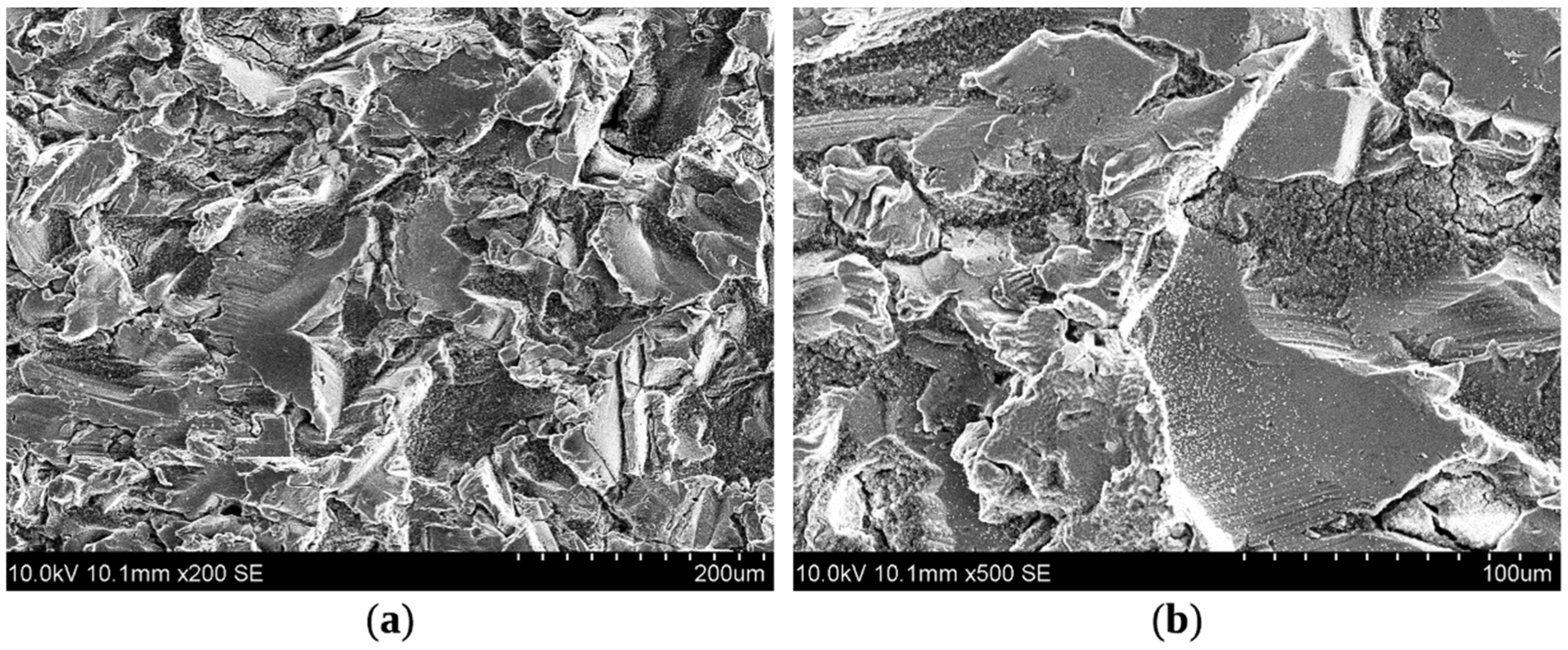
The feedstock powder described above was sprayed afterwards using a low-pressure cold spray to prepare superhydrophobic coatings. General view on the topography of the as-sprayed coating (Figure 6) presents not only the multiple bright regions being the highest peak asperities but also the number of structural macropores visible as darker zones. In those valleys of roughness, it is possible to recognize a high concentration of SiO2–F particles yet at magnification 500 times. Additionally, commonly the smooth plateaus are covered with a number of silica spheres brighter than the captured aluminium substrate.
It is important to note that the low magnifications of cold-sprayed coating depict practically identical images as presented for the sand-blasted state (Figure S3) which means that the sand-blasting created micro-roughness preserved in the final coating. As it is well known the pretreatment of the substrate may drastically change the hydrophobicity of the final coating [66], in this work irregular Al2O3 particles with a mean diameter 350 μm were applied to roughen aluminium substrates because it is believed that substrate surface modification introduced by sandblasting is crucial to facilitate SiO2–F anchoring.
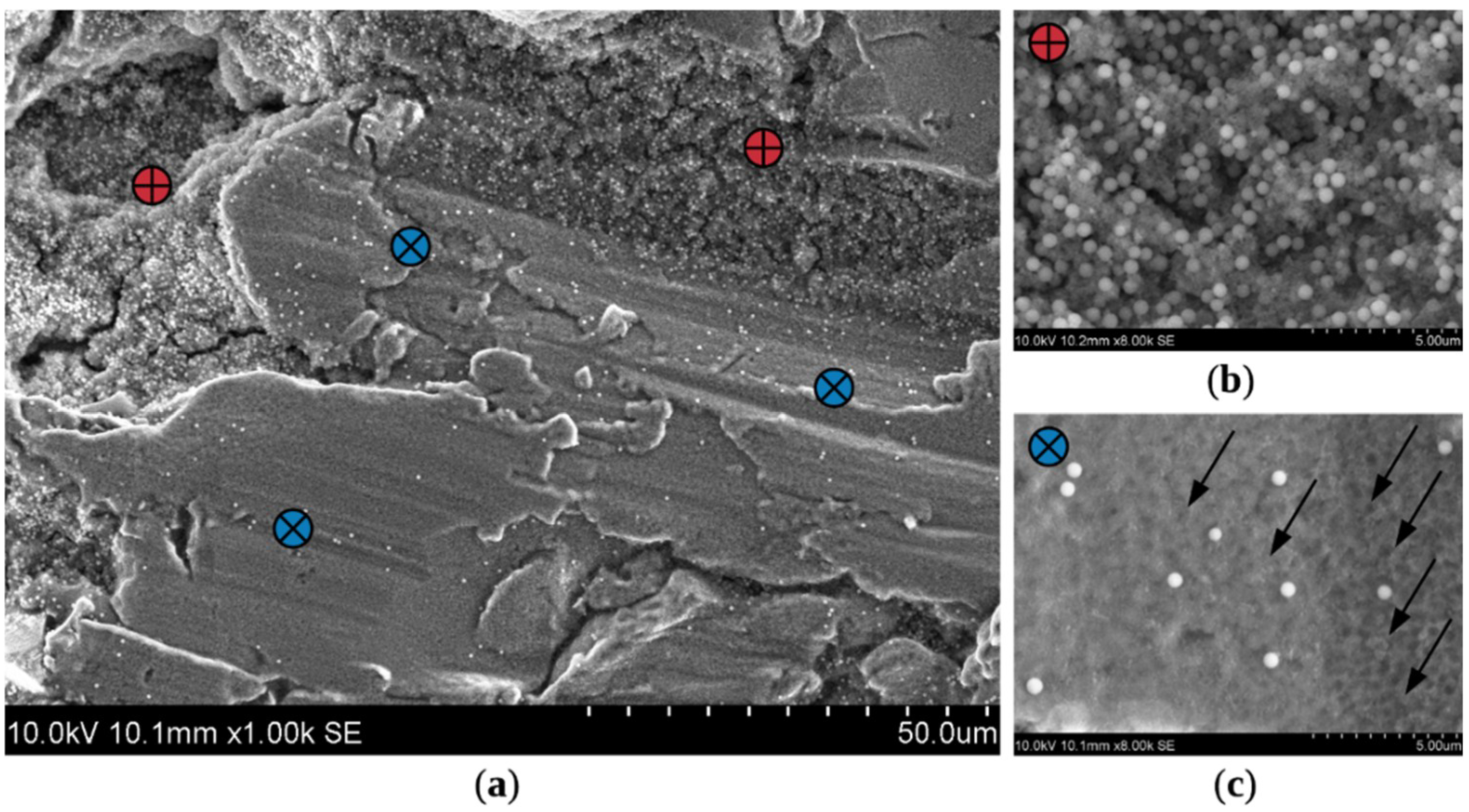
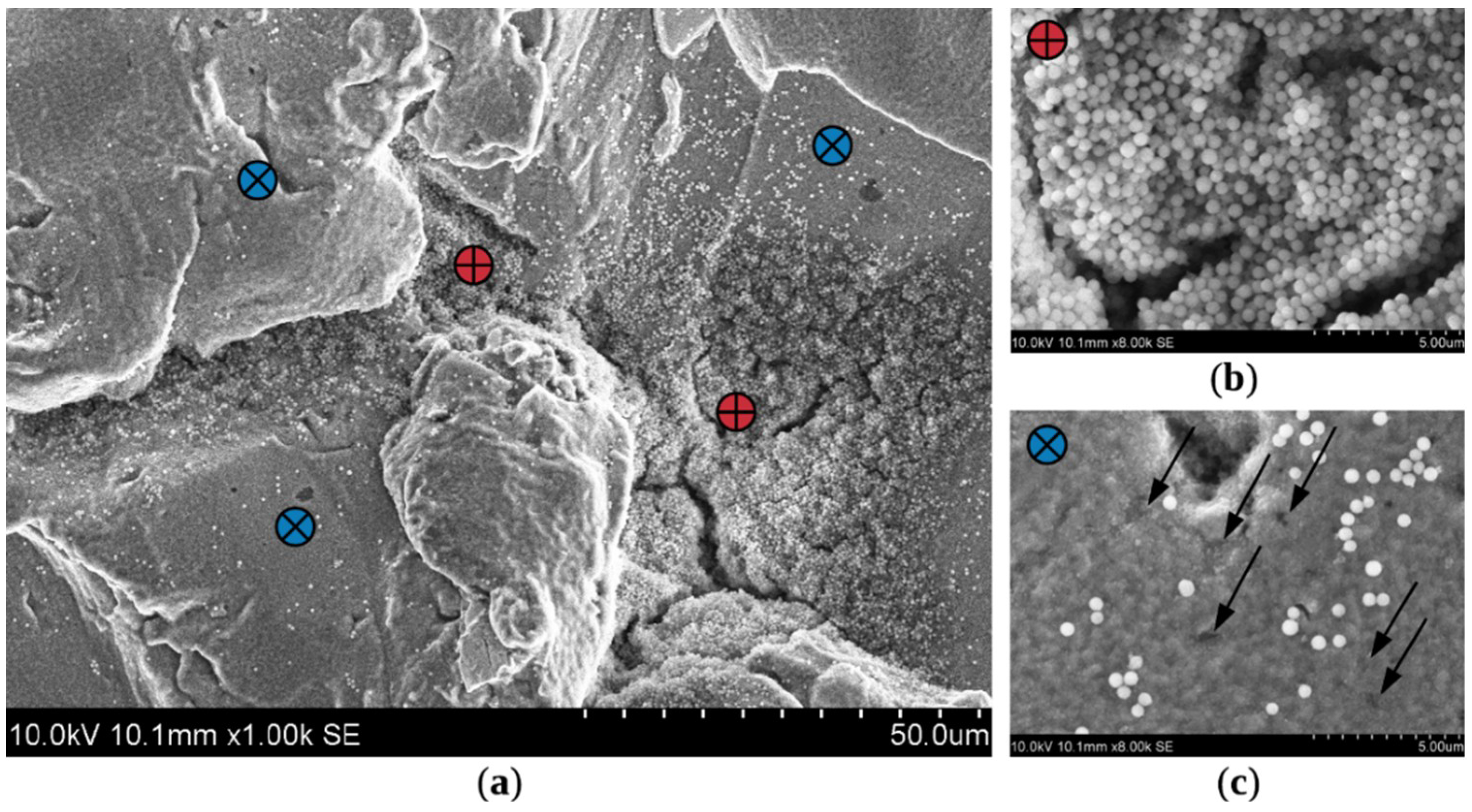
A further comparison of the sprayed coating with the surface of the sandblasted substrate (Figure S3) allows observing the difference in the form of heterogeneity on the sub-micron scale which depicts the second level of formed roughness (Figure 7). Two main distinct regions (denoted by letters a and b in Figure 7) are present interchangeably which is coincident with distribution visible at micro-scale. A-zone is typically observed within valleys as they are potential hot spots for adhering the first particles while spraying. It enables the following particles to get attached to already anchored spheres afterwards. Such densification of already deposited coating interlocks adjacent silica particles which reduces voids between them [2,23]. On the contrary, there is the second above-stated region, b-zone, which does not encourage coating built-up. This is recognized by the limited number of SiO2–F spheres which successfully anchored within the plateaus. As observed on SEM pictures (Figure 7) only individual particles embedded in the substrate material. Additionally, it is even more apparent that the sphere-like deformation pattern was formed while spraying (Figure 7 and Figure S3). The multiple imprints of approximately SiO2–F spheres size (marked with arrows in Figure 7) are very similar to the indentation marks generated by shot peening [12,67,68,69] commonly used for altering the mechanical properties of metals.
In shot peening impact of particles causes compressing the substrate material beneath the dents. Similarly, while cold spraying the SiO2–F particles rebound from a surface of substrate causing substrate plastic deformation. The more particles impact the substrate, the more dents are formed. Subsequently, the substrate became harder which hinders the attachment of new particles. In case of SiO2–F particles which are rather softer than shoots used for shot peening, different mechanism basing on the particles rebounds play the main role [69]. As the particle approaches the surface of the substrate it loses part of the energy for adhering or rebounding. While anchoring the whole kinetic energy of feedstock particles is converted into heat and deformation of the substrate. While rebound the feedstock particles kinetic energy is only partly converted and particles can reflect at some angle instead of adhering. As many particles rebound from the substrate, the shock wave being a barrier for incoming particles is created. The application of appropriate pressure and temperature of the stream can reduce the effect of the barrier, but it means that while the rebound particles are pushed at other places. After sand-blasting (Figure S3) the substrate material in a-zones is highly irregular and rough. While spraying most likely multi-rebound occurs and finally, particles without kinetic energy are directed by the gas streams containing feedstock powder to the cavities of roughness. Then tamping by incoming particles lead to proper embedding of particles and then finally built-up of the hydrophobic coating. As b-zones are almost flat after pretreatment (Figure S3) they promote particles reflecting and falling at different places often out of the substrate. Then incoming particles may cause the proper anchoring of particle or again shifting to a different region.
Since the alternation of roughness is provided for the whole investigated region–either by embedding SiO2–F particles or creating the net of imprints-it promotes achieving high hydrophobicity. In accordance with the principle that superhydrophobic surface must possess hierarchical multi-level roughness, it can be concluded the nonuniform pattern formed by anchoring-rebound of particles alters the roughness of the substrate forming such required multi-level structure and thus may contribute in the enhancement of hydrophobicity [70].
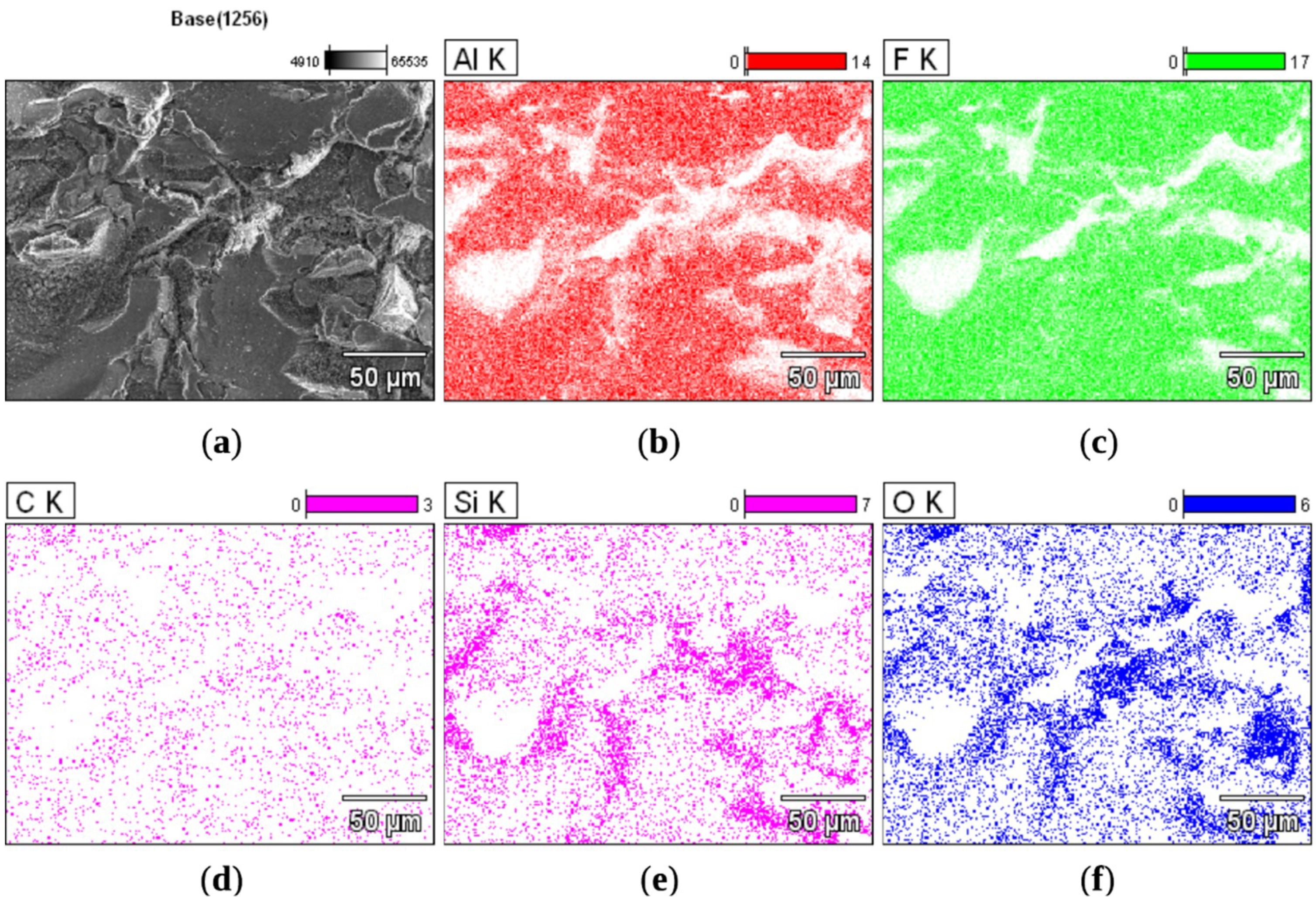
The anchoring of SiO2–F particles is facilitated not only by the former surface roughness described earlier but also by the low-surface-energy chemical composition of the feedstock powder forming the coating. For that reason, the distribution of the SiO2–F spheres was precisely investigated in the EDX maps (Figure 8). White zones being at the same time highest peak asperities are lacking any signal due to inappropriate face orientation with respect to the detector. Most probably it also translates into the adverse orientation of observed zones in respect to the spraying gun. Besides these regions, the presence of silicon (Figure 8e) and oxygen (Figure 8f) creating SiO2 spheres is revealed on the whole measured area. Full of silica spheres a-zones and b-zones with single SiO2–F particles are clearly visible. The accumulation of silica particles in macropores causing the completion of valleys (Figure 7) results in the higher distribution density of silica spheres in a-zones. Likewise, the attachment-rebound pattern within plateaus roughening the substrate (Figure 7) makes maps of b-zones richer in aluminium (Figure 8b) than silicon (Figure 8e) and oxygen (Figure 8f). Although a- and b-zones are clearly distinguishable due to Si, O, Al contents the fluorine (Figure 8c) is detected throughout the elemental maps with no distinction between zones maintaining the same tightly-packed pattern all over. A similar phenomenon was observed on the maps of prepared feedstock powder (Figure 3) where the distribution of fluorine was ascribed to the presence of FOTS sheaths. After the analysis of coating EDX maps, it may be concluded that those fluorocarbon clouds are still present after spraying. At this point, it is necessary to briefly recall that the temperature of spraying gas was 600 °C and decomposition of fluorocarbon chains proceeds at ~550 °C (Figure 5) which means that the whole SiO2–F powder withstands the temporary temperature growth when being accelerated in the spraying gun. But at the same time, it is proven that the high kinetic energy does have an impact on the SiO2–F particles by facilitating the FOTS sheath division when approaching the substrate. The outer sheath only physically attached to functionalized silica spheres is left on the substrate and the inner sheath rebound or anchor together with the silica core [34,35]. Thus, the resultant pattern of imprints contains fluorine in the amount comparable to a-zones. Most probably at the beginning of the valley completion, this phenomenon of separation of the outer sheath is also present. Nonetheless, the tamping of the number of SiO2–F particles makes no distinction between fluorocarbon chains originating from the detached FOTS clouds and FOTS shells chemically bonded with the silica cores. Finally, it can be assumed that due to the size of the cauliflower-like sheath being significantly smaller than SiO2–F itself the next level of structure complexity (nano-roughness) is provided into the system.

3.4. Characterization of Superhydrophobicity Durability of Coatings

Next step of characteristics of coatings comprised the wettability measurements by means of water contact angle (CA) measurements (Figure 9). The droplets were put within distinct random places of the whole surface of the coating to determine the static behaviour of water. As-prepared SiO2–F coatings were tested initially. The observed droplets were of nearly-spherical shape which indicates good hydrophobic properties. Additionally, CA always exceeded minimum 150° which finally lead to CA value being 153.1° ± 2.1°. The low standard deviation of CA measurement indicates the uniformity of hydrophobic character with no distinction between zones own mainly to the uniform distribution of fluorinated silica spheres and cloud-like FOTS structures present on the surfaces as confirmed by the EDX analyses (Figure 8). High water contact value is attributed to the multi-level roughness pattern obtained on the whole substrate surface of SiO2–F coating. However, each level of roughness contributes to the enhancement of specific wetting behaviour [71,72,73].
The microscale roughness is introduced by sandblasting and it is shown that after coating deposition it is still maintained. Wetting the microscale roughness level provokes to form composite interference necessary for Cassie-Baxter wetting [74,75], which means that the water does not penetrate the asperities of the surface. The submicron level of roughness is formed by the anchoring-rebound behaviour of modified silica particles. Additionally, nanoscale asperities are present due to the intrinsic structure of sheath covering silica spheres or detached outer sheath anchored in the substrate. Nanoscale roughness entraps some portion of air in nanopockets which prevents condensation of nanodroplets which additionally promotes maintaining composite interference [71,72,73,74]. The combination of all levels of roughness facilitates the final superhydrophobicity of the investigated coating.
Since the superhydrophobic properties of the coatings result from two contributing factors, surface energy and surface topography, it can be concluded that the coating may lose hydrophobic character due to the change of roughness or alteration of the chemical composition of the surface. For that reason, the number of unfavourable conditions was applied to evaluate the durability of SiO2–F coating, being mechanical wear (Figure 9a), thermal treatment (Figure 9b), soaking in water and absolute alcohol (Figure 9c), and ultrasonic bath in absolute alcohol (Figure 9d).
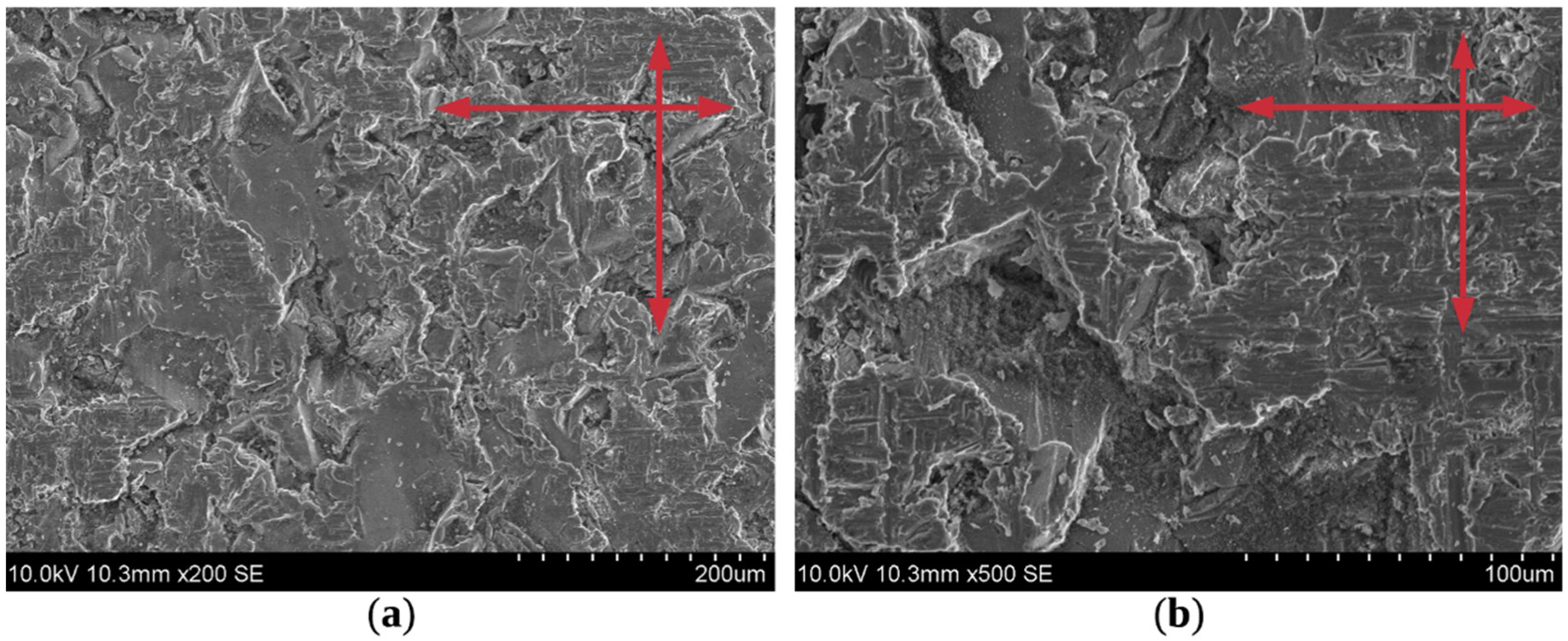
Loss of roughness was provoked by mechanical wear test (Figure 9a). The abrasion test was conducted by sliding the specimen over the abrasive paper grit 800. Taking into account the standard deviation the first 0.15 m slid had insignificant influence on the hydrophobicity of the coating resulting in degrease of CA from 153.1° to 151.6°. The next 0.15 m lead to lowering CA slightly below the superhydrophobic level to 149.4°. Then the CA drops about 2° per every 0.6 m. The potential causes of hydrophobicity loss were investigated using SEM. Analysis of the SEM pictures (Figure 10 and Figure S4) shows that the sliding on the sandpaper modified the roughness of the substrate and coating. In the areas of removed material, distinct scratches onto the substrate surface in two directions are clearly visible. As mainly the peaks of the profile were subjected to the abrasion process, maximum peak height is decreased at first. Successively, the plateau regions are also covered with multiple abrasion marks which means that the imprints pattern was gradually erased which led subsequently to a progressive loss of multi-level roughness. Not only was the substrate material removed but sequentially also anchored SiO2–F particles and cloud-type FOTS residues. Thus, both losses of hydrophobic agent and hierarchical roughness within the plateaus lead eventually to increasing of surface energy and lowering the CA in turn. Simultaneously, any change in the sub-micron structure of valleys was observed at the high-magnification level (Figure S4, magnification 4000). Thus, even the sample slid 5.55 m over the sandpaper still preserves the hydrophobic character within a-zones. Most probably the external layer of valley fulfilment was also altered during abrasion, but it does not influence the particles accumulated just beneath them.
Moreover, the above-described nonuniformity of the surface structure, being worn plateaus and preserved valleys, significantly increases the standard deviations of measured CA values with increasing sliding distance. Since the a-zones still maintain high hydrophobic potential and neighbouring b-zones are deprived of hydrophilizing agent and multi-level roughness, the place of drop putting becomes decisive for the obtained CA value. Still, some post-treatment methods such as painting [62] or application of epoxy resin [59] can be applied to reduce wear of samples but it may hamper the hydrophobic character. The more detailed mechanical robustness tests including stretching, compression, abrasion, knife-scratch test etc. and adhesion strength tests can be also performed to evaluate the potential mechanical applications.
The influence of alternation of multi-scale roughness and chemical composition was tested evaluating the thermal stability of SiO2–F coating at elevated temperatures (Figure 9b). The temperature effect on the superhydrophobicity of the coatings was investigated by means of 2 h-annealing at different temperatures varying from 100 to 500 °C and then quenching in air. The CA change was found to be negligible within the standard deviation range up to 300 °C which indicates that the SiO2–F coating maintains its superhydrophobicity up to this temperature (CA: 153.2° for 100 °C, 154.0° for 200 °C and 148.9° for 300 °C). From the analysis of the next measurement point it is clear that at 350 °C, the superhydrophobicity was significantly reduced (CA ~ 127°). At 400 °C, the decreasing trend is continued, and the surface changed to a hydrophilic state (CA ~ 44°). Finally, in 500 °C, the surface turned out to be superhydrophilic. Taking into account thermogravimetric measurement of SiO2–F powder (Figure 5) the hydrophobic-hydrophilic change in the nature of a surface should be associated with the decomposition of the functionalizing precursor modifying the surface of SiO2 spheres starting at about 450 °C at a heating rate 5 K·min−1 simulated in DSC/TG measurement. From the analysis of SEM micrographs (Figure 11 and Figure S5) it is clearly visible that after the annealing at 500 °C morphology of the surface of the SiO2–F coating is surprisingly very similar to as-sprayed state at the macroscopic view. The detailed view shows that the zonal character is preserved after the annealing but the SiO2–F particles within valleys and imprints pattern become more distinct. It is a result of decomposition of fluorocarbon structures coming from FOTS which after 2-h annealing in temperature 500 °C are completely lost. A similar findings regarding fluorinated electro sprayed coatings are presented by Kim et al. [57,58] but due to addition of different functionalizing agent (trichloro(1H,1H,2H,2H-perfluorooctyl)silane) during post-treatment it was possible to impart high hydrophobic potential maintained even to 400 °C which is interesting future perspective for this research.
The changes in chemical composition were evaluated by soaking in popular liquids and placing in alcohol ultrasonic bath. Since chemical stability is a key variable in the selection of materials for application in a particular environment, every attempt to determine it becomes very important. For this reason, the resistance of the coating to water and alcohol environment was investigated. The changes of contact angles on the route of soaking in water and absolute alcohol (Figure 9c) present different tendencies of CA. The absolute alcohol environment facilitates the maintaining or even enhancement of high hydrophobicity. The immersion in absolute alcohol for 90 h in total preserved the CA on the initial level (Figure 9c). It is interesting to note that between 18 and 66 h of the test there is a slight increase in hydrophobicity visible from CA equal 153.1° to 153.7°. The explanation for this unexpected behaviour requires a re-examination of the surface of the SiO2–F spheres. The increase in the hydrophobicity of silica powder after soaking in alcohol has been recently explained by Björklund et al. [76] and bases on the fact that alcohol treatment at room temperature introduces alkoxy groups (–O–C2H5 in the case of soaking in ethanol) that are being covalently bounded with the silica surface. The occurrence of these functional groups is associated with the chemical reaction of an alcohol with –OH groups on the silica surface. As it was underlined above, in the chapter dedicated to feedstock powder characterization, after the modification of SiO2 spheres with fluorocarbon FOTS groups, their surface due to steric barriers still contains some blocked –OH groups. Thus, it can be suggested that these residual –OH groups, when soaked in alcohol, undergo a reaction that converts them into more hydrophobic –O–C2H5 groups. Finally, since there is an only small number of hydroxyl groups on the surface of SiO2–F to be replaced by –O–C2H5 groups apparent growth of CA is also insignificant. Nevertheless, this small amount can be still successfully utilized during alcohol treatment in higher molecular weight alcohol as shown in [76] to obtain even higher enhancement of hydrophobicity. Moreover, the hydrophobicity enhancement is not observed in the case of modified corundum mixed with silica [38].
Taking into account that the number of alkoxy and hydroxy group is not constant, the water environment is applied as the next step of hydrophobicity durability testing. Immersion in water leads to a slight but noticeable CA reduction (Figure 9c), and hence a different to alcohol model of behaviour is observed [60]. However, within the first 18 hours of the bath, contact angle still remains above the superhydrophobic limit (CA 151.8°), the water environment leads to loss of hydrophobicity rather quickly which is proved by CA change of about 5° every 24 h. It is worth noting that the curve has a similar course to the modified vacuum Al2O3&SiO2 immersed in alcohol [38]. The interpretation of this phenomena involves, similarly to presented above alcohol influence explanation, the analysis of the surface of SiO2–F spheres. After the modification of the spheres with FOTS, chemically attached long fluorocarbon chains are grafted to the surface of SiO2. Along with them a certain amount of ethoxy groups (–OC2H5 for ethanol) is also present as a consequence of the chemical structure of triethoxy(1H,1H,2H,2H-perfluoro-1-octyl)silane (in FOTS the central atom Si is bonded with 3 ethoxy groups and single fluorocarbon chain). For that reason, the number of ethoxy groups occurs both on the silica surface and in the FOTS structures described above. Referring to the explanation given by Ek et al. [64], soaking in water should cause the effect opposite to that in alcohol. Ethoxy groups treated with water are replaced with hydrophilic –OH groups, which causes a decrease in hydrophobicity. But, nevertheless, it should be pointed out that even after 90 h of soaking, the coating is still hydrophobic (136°). This is strictly connected with the limited number of –OC2H5 groups that could be exchanged for hydroxyl groups. Additionally, the presence of large number alkoxy group on the surface of silica particles, for example after alcohol treatment, may hamper the water sorption capability [76], which at the same time seems to be an interesting alternative for post-treatment of the coating described in this paper.
For the last testing, the coating by immersion in an ultrasonic bath in absolute alcohol is investigated (Figure 9d) that indicates that exposure to an ultrasonic bath causes a fairly rapid reduction of hydrophobicity. Unfortunately, just 20 min was enough to reduce CA below 150°. Then the CA was gradually decreased about 2°–3° every 20 min. Evidently, very high forces induced by high-frequency waves generated during a sonic bath gradually impair the adhesion of the outer, least-connected SiO2–F particles.

4. Conclusions

In this study, a new approach presenting the cold spray deposition of superhydrophobic coatings is demonstrated, which offer undeniably great potential for further development and is suitable for a variety of application in new areas. The analysis of all collected data leads to the conclusion that several factors contributed to this success.
One of the most important elements is the control over the feedstock powder from the molecular level to finally deposited coating. This especially allowed to design and produce superhydrophobic coating far beyond the conventional range of applications of the cold spray method. In the paper, great emphasis is put on the optimization of the feedstock powder to obtain maximal functionality with the minimal amount of functionalizing agent. For that reason, the final coating is sprayed with silica particles modified with a slight excess of the hydrophobic agent. The excess is proved to be necessary for the formation of two-layer structures which differ in the bonding type with regards to SiO2 particles. These three-dimensional sheaths on SiO2 particles resembling cauliflowers are either in the form of very thin layers, chemically bonded to submicron SiO2 spheres (inner layers) or in the form of only physically attached loose structures (outer layers). Additionally, due to the control over the whole process, the cauliflower-like sheaths are preserved by abandoning post-treatment (cleaning, heat treatment).
The use of such self-prepared SiO2 powder covered with hydrophobic cauliflower-like sheaths not only allowed to obtain a coating characterized by the desired low surface energy but also enabled a multilevel roughness pattern necessary to increase and maintain the hydrophobic properties. It is the form of silica particles which produce the uniformity of hydrophobic behaviour for the whole tested coating—the FOTS chains block water penetration by entrapping the air and hence the composite interference formed by the nanolevel roughness is maintained. It is explained in the paper, that whenever the silica particle is anchored to the substrate it is covered with the inner sheaths (chemically bonded to submicron SiO2 sphere) and the silica-free regions are full of outer hydrophobic sheaths detached during the impact from SiO2–F spheres which result in the formation of uniform functionating agent layer on the substrate. Additionally, before coating deposition, the sandblasting of the substrate material surface facilitates the formation of microscale roughness. In that manner, the particles approaching substrate reach two different surface regions–valleys and plateaus. Anchoring of particles leads to the completion of cavities with silica particles covered with fluorine sheaths and production of the net of dents filled with detached outer sheaths, respectively. It is important to emphasize that the anchoring process is connected with loosing of kinetic energy on anchoring-and-rebounding and then being tamped by incoming particles. Even though the number of SiO2–F particles in valleys and plateaus is considerably different the FOTS structures are distributed evenly which in the end produces the uniformity of hydrophobic behaviour for the whole deposited coating.
The wide range of performed durability tests investigated the trends to lose or gain this hydrophobicity and allowed to determine the course for future research. Always, the number of active hydroxyl groups remained after synthesis is very important: by replacing this hydroxy groups with alkoxy groups by chemical treatment with alcohol it is possible to enhance hydrophobicity and by replacing alkoxy groups with hydroxy groups while contact with water it is possible to slightly lower the hydrophobic potential of the coating. The worsening of hydrophobicity may be also introduced by the ultrasonic bath which causes detachment of physically bonded FOTS structure from the substrate. A total change to hydrophilic character may be introduced by annealing in temperature over 500 °C, but at the same time introduction of powder to the gas stream heated up to 600 °C while spraying does not cause the decomposition of FOTS. During wear test, it is shown that the valleys regions maintain high hydrophobicity and the drop of CA angles during prolonged friction is only ascribed to the surface modification of plateaus.
Hence, the type of feedstock material used in this work for spraying the coating, as well as its small thickness distinguishes the produced coating from the ordinary ones manufactured with cold spray. The presented solution is the next step of CS development. Finally, considering the provided functionality, the small thickness of the produced coatings is only an advantage. For all these reasons, the suggested solution is a simple and fast way to prepare functionalized coatings, maintaining the future industrial applicability and truly fundamental research character.

Supplementary Materials

The following are available online at https://www.mdpi.com/2079-6412/9/12/829/s1, Figure S1: Scheme of functionalization process, Figure S2: Wettability of coating SiO2–Fx as a measure of contact angle (where x denotes the added amount of FOTS), Figure S3: SEM images of substrate material (a–1,a–2) after sand-blasting and (b–1,b–2) after cold-spraying with SiO2–F powder on the previously sandblasted substrate, Figure S4: SEM images of coatings (a) in the as-prepared form and (b) after abrasive wear test on the distance 5.55 m, Figure S5: SEM images of 2 h-annealed coating at different temperatures: (a) as-prepared with no heat-treatment and heat-treated at (b) 350 °C, (c) 400 °C, (d) 500 °C.

Author Contributions

Conceptualization, A.B., A.G., M.J. and M.W.; methodology, A.B., M.J., A.G. and M.W.; software, A.G.; validation, A.B., M.J. and A.G.; formal analysis, A.G. and A.B.; investigation, A.G., A.B., M.J. and M.W.; resources, M.J., A.B. and M.W.; data curation, A.G.; writing—original draft preparation, A.G. and A.B.; writing—review and editing, A.G. and A.B..; visualization, A.G.; supervision, M.J.; project administration, A.G. and A.B.; funding acquisition, M.W. and M.J.

Funding

The research was funded by the Polish National Science Centre under contract No. 2016/23/D/ST8/00675 (Project title: The mechanism of joining submicron ceramic particles in cold spraying process). Additional support was provided by the Department of Mechanics, Materials Science and Engineering, Wroclaw University of Science and Technology under contract No. 049U/0013/19.

Acknowledgments

A.G. acknowledge special thanks to Małgorzata Małecka, Institute of Low Temperature and Structure Research, Polish Academy of Sciences for involvement and guidance in TEM and SEM measurements.

Conflicts of Interest

The authors declare no conflict of interest. The funders had no role in the design of the study; in the collection, analyses, or interpretation of data; in the writing of the manuscript, or in the decision to publish the results.

References

  1. Papyrin, A. Cold spray technology. Adv. Mater. Process. 2001, 159, 49–51. [Google Scholar]
  2. Moridi, A.; Hassani-Gangaraj, S.M.; Guagliano, M.; Dao, M. Cold spray coating: Review of material systems and future perspectives. Surf. Eng. 2014, 36, 369–395. [Google Scholar] [CrossRef]
  3. Tejero-Martin, D.; Rezvani Rad, M.; McDonald, A.; Hussain, T. Beyond traditional coatings: A review on thermal-sprayed functional and smart coatings. J. Therm. Spray Technol. 2019, 28, 598–644. [Google Scholar] [CrossRef] [Green Version]
  4. Irissou, E.; Legoux, J.-G.; Ryabinin, A.N.; Jodoin, B.; Moreau, C. Review on cold spray process and technology: Part I—intellectual property. J. Therm. Spray Technol. 2008, 17, 495–516. [Google Scholar] [CrossRef] [Green Version]
  5. Wank, A. Basics of Thermal Spray Technology; GTV Verschleiss-Schutz GmbH: Luckenbach, Germany, 2006. [Google Scholar]
  6. Nikbakht, R.; Seyedein, S.H.; Kheirandish, S.; Assadi, H.; Jodoin, B. The role of deposition sequence in cold spraying of dissimilar materials. Surf. Coat. Technol. 2019, 367, 75–85. [Google Scholar] [CrossRef]
  7. Lupoi, R.; O’Neill, W. Deposition of metallic coatings on polymer surfaces using cold spray. Surf. Coat. Technol. 2010, 205, 2167–2173. [Google Scholar] [CrossRef] [Green Version]
  8. Hassani-Gangaraj, M.; Veysset, D.; Champagne, V.K.; Nelson, K.A.; Schuh, C.A. Adiabatic shear instability is not necessary for adhesion in cold spray. Acta Mater. 2018, 158, 430–439. [Google Scholar] [CrossRef]
  9. Xie, F.; Zhang, W.; Li, H.; Fan, X. Modelling of alloying process of cold sprayed Ni/Al coating. Mech. Mater. 2019, 135, 129–143. [Google Scholar] [CrossRef]
  10. Bolelli, G.; Dosta, S.; Lusvarghi, L.; Manfredini, T.; Guilemany, J.M.; Cano, I.G. Building up WC-Co coatings by cold spray: A finite element simulation. Surf. Coatings Technol. 2019, 374, 674–689. [Google Scholar] [CrossRef]
  11. da Silva, F.S.; Cinca, N.; Dosta, S.; Cano, I.G.; Guilemany, J.M.; Benedetti, A.V. Cold gas spray coatings: Basic principles corrosion protection and applications. Eclética Química J. 2017, 42, 9. [Google Scholar] [CrossRef] [Green Version]
  12. Winnicki, M.; Baszczuk, A.; Jasiorski, M.; Borak, B.; Małachowska, A. Preliminary studies of TiO2 nanopowder deposition onto metallic substrate by low pressure cold spraying. Surf. Coat. Technol. 2019, 371, 194–202. [Google Scholar] [CrossRef]
  13. Baszczuk, A.; Jasiorski, M.; Winnicki, M. Low-temperature transformation of amorphous sol–gel TiO2 powder to anatase during cold spray deposition. J. Therm. Spray Technol. 2018. [Google Scholar] [CrossRef] [Green Version]
  14. Ravi, K.; Sulen, W.L.; Bernard, C.; Ichikawa, Y.; Ogawa, K. Fabrication of micro-/nano-structured super-hydrophobic fluorinated polymer coatings by cold-spray. Surf. Coatings Technol. 2019, 373, 17–24. [Google Scholar] [CrossRef]
  15. Vilardell, A.M.; Cinca, N.; Dosta, S.; Cano, I.G.; Guilemany, J.M. Feasibility of using low pressure cold gas spray for the spraying of thick ceramic hydroxyapatite coatings. Int. J. Appl. Ceram. Technol. 2019, 16, 221–229. [Google Scholar] [CrossRef] [Green Version]
  16. Wang, N.; Xiong, D.; Deng, Y.; Shi, Y.; Wang, K. Mechanically robust superhydrophobic steel surface with anti-icing, UV-durability, and corrosion resistance properties. ACS Appl. Mater. Interfaces 2015, 7, 6260–6272. [Google Scholar] [CrossRef] [PubMed]
  17. Hassani-Gangaraj, S.M.; Moridi, A.; Guagliano, M. Critical review of corrosion protection by cold spray coatings. Surf. Eng. 2015, 31, 803–815. [Google Scholar] [CrossRef]
  18. Latthe, S.S.; Sudhagar, P.; Devadoss, A.; Kumar, A.M.; Liu, S.; Terashima, C.; Nakata, K.; Fujishima, A. A mechanically bendable superhydrophobic steel surface with self-cleaning and corrosion-resistant properties. J. Mater. Chem. A 2015, 3, 14263–14271. [Google Scholar] [CrossRef]
  19. Zheng, S.; Li, C.; Fu, Q.; Xiang, T.; Hu, W.; Wang, J.; Ding, S.; Liu, P.; Chen, Z. Fabrication of a micro-nanostructured superhydrophobic aluminum surface with excellent corrosion resistance and anti-icing performance. RSC Adv. 2016, 6, 79389–79400. [Google Scholar] [CrossRef]
  20. Zhang, D.; Wang, L.; Qian, H.; Li, X. Superhydrophobic surfaces for corrosion protection: A review of recent progresses and future directions. J. Coatings Technol. Res. 2016, 13, 11–29. [Google Scholar] [CrossRef] [Green Version]
  21. Gąsiorek, J.; Szczurek, A.; Babiarczuk, B.; Kaleta, J.; Jones, W.; Krzak, J. Functionalizable sol-gel silica coatings for corrosion mitigation. Materials 2018, 11, 197. [Google Scholar] [CrossRef] [Green Version]
  22. Deng, X.; Mammen, L.; Zhao, Y.; Lellig, P.; Müllen, K.; Li, C.; Butt, H.J.; Vollmer, D. Transparent, thermally stable and mechanically robust superhydrophobic surfaces made from porous silica capsules. Adv. Mater. 2011, 23, 2962–2965. [Google Scholar] [CrossRef]
  23. Barthlott, W.; Neinhuis, C. Purity of the sacred lotus, or escape from contamination in biological surfaces. Planta 1997, 202, 1–8. [Google Scholar] [CrossRef]
  24. Lu, H.; Zheng, Y.; Yin, W.; Tao, D.; Pesika, N.; Meng, Y.; Tian, Y. Propulsion principles of water striders in sculling forward through shadow method. J. Bionic Eng. 2018, 15, 516–525. [Google Scholar] [CrossRef]
  25. Falde, E.J.; Yohe, S.T.; Colson, Y.L.; Grinstaff, M.W. Superhydrophobic materials for biomedical applications. Biomaterials 2016, 104, 87–103. [Google Scholar] [CrossRef] [PubMed] [Green Version]
  26. Gogolides, E.; Ellinas, K.; Tserepi, A. Hierarchical micro and nano structured, hydrophilic, superhydrophobic and superoleophobic surfaces incorporated in microfluidics, microarrays and lab on chip microsystems. Microelectron. Eng. 2015, 132, 135–155. [Google Scholar] [CrossRef]
  27. Li, L.; Tian, J.; Li, M.; Shen, W. Superhydrophobic surface supported bioassay—An application in blood typing. Colloids Surf. B Biointerfaces 2013, 106, 176–180. [Google Scholar] [CrossRef]
  28. Shiu, J.-Y.; Chen, P.L. Addressable protein patterning via switchable superhydrophobic microarrays. Adv. Funct. Mater. 2007, 17, 2680–2686. [Google Scholar] [CrossRef]
  29. Gentile, F.; Coluccio, M.L.; Coppedè, N.; Mecarini, F.; Das, G.; Liberale, C.; Tirinato, L.; Leoncini, M.; Perozziello, G.; Candeloro, P.; et al. Superhydrophobic surfaces as smart platforms for the analysis of diluted biological solutions. ACS Appl. Mater. Interfaces 2012, 4, 3213–3224. [Google Scholar] [CrossRef]
  30. Li, L.; Li, B.; Dong, J.; Zhang, J. Roles of silanes and silicones in forming superhydrophobic and superoleophobic materials. J. Mater. Chem. A 2016, 4, 13677–13725. [Google Scholar] [CrossRef]
  31. Matsubayashi, T.; Tenjimbayashi, M.; Manabe, K.; Kyung, K.-H.; Ding, B.; Shiratori, S. A facile method of synthesizing size-controlled hollow cyanoacrylate nanoparticles for transparent superhydrophobic/oleophobic surfaces. RSC Adv. 2016, 6, 15877–15883. [Google Scholar] [CrossRef] [Green Version]
  32. Yang, G.J.; Li, C.J.; Han, F.; Li, W.Y.; Ohmori, A. Low Temperature deposition and characterization of TiO2 photocatalytic film through cold spray. Appl. Surf. Sci. 2008, 254, 3979–3982. [Google Scholar] [CrossRef]
  33. Toibah, A.R.; Sato, M.; Yamada, M.; Fukumoto, M. Cold-sprayed TiO2 coatings from nanostructured ceramic agglomerated powders. Mater. Manuf. Process. 2016, 31, 1527–1534. [Google Scholar] [CrossRef]
  34. Rahim, T.A.; Takahashi, K.; Yamada, M.; Fukumoto, M. Effect of powder calcination on the cold spray titanium dioxide coating. Mater. Trans. 2016, 57, 1345–1350. [Google Scholar] [CrossRef] [Green Version]
  35. Salim, N.T.; Yamada, M.; Nakano, H.; Shima, K.; Isago, H.; Fukumoto, M. The effect of post-treatments on the powder morphology of titanium dioxide (TiO2) powders synthesized for cold spray. Surf. Coat. Technol. 2011, 206, 366–371. [Google Scholar] [CrossRef]
  36. Assadi, H.; Gärtner, F.; Stoltenhoff, T.; Kreye, H. Bonding mechanism in cold gas spraying. Acta Mater. 2003, 51, 4379–4394. [Google Scholar] [CrossRef]
  37. Hussain, T.; McCartney, D.G.; Shipway, P.H. Impact phenomena in cold-spraying of titanium onto various ferrous alloys. Surf. Coat. Technol. 2011, 205, 5021–5027. [Google Scholar] [CrossRef]
  38. Li, J.; Zhang, Y.; Ma, K.; Pan, X.-D.; Li, C.-X.; Yang, G.-J.; Li, C.-J. Microstructure and transparent super-hydrophobic performance of vacuum cold-sprayed Al2O3 and SiO2 aerogel composite coating. J. Therm. Spray Technol. 2018, 27, 471–482. [Google Scholar] [CrossRef]
  39. Zou, X.; Tao, C.; Yang, K.; Yang, F.; Lv, H.; Yan, L.; Yan, H.; Li, Y.; Xie, Y.; Yuan, X.; et al. Rational design and fabrication of highly transparent, flexible, and thermally stable superhydrophobic coatings from raspberry-like hollow silica nanoparticles. Appl. Surf. Sci. 2018, 440, 700–711. [Google Scholar] [CrossRef]
  40. Vilardell, A.M.; Cinca, N.; Cano, I.G.; Concustell, A.; Dosta, S.; Guilemany, J.M.; Estradé, S.; Ruiz-Caridad, A.; Peiró, F. Dense nanostructured calcium phosphate coating on titanium by cold spray. J. Eur. Ceram. Soc. 2017, 37, 1747–1755. [Google Scholar] [CrossRef]
  41. Cinca, N.; Vilardell, A.M.; Dosta, S.; Concustell, A.; Garcia Cano, I.; Guilemany, J.M.; Estradé, S.; Ruiz, A.; Peiró, F. A new alternative for obtaining nanocrystalline bioactive coatings: Study of hydroxyapatite deposition mechanisms by cold gas spraying. J. Am. Ceram. Soc. 2016, 99, 1420–1428. [Google Scholar] [CrossRef]
  42. Yin, S.; Cavaliere, P.; Aldwell, B.; Jenkins, R.; Liao, H.; Li, W.; Lupoi, R. Cold spray additive manufacturing and repair: Fundamentals and applications. Addit. Manuf. 2018, 21, 628–650. [Google Scholar] [CrossRef]
  43. Sun, W.; Bhowmik, A.; Tan, A.W.Y.; Li, R.; Xue, F.; Marinescu, I.; Liu, E. Improving microstructural and mechanical characteristics of cold-sprayed inconel 718 deposits via local induction heat treatment. J. Alloys Compd. 2019, 797, 1268–1279. [Google Scholar] [CrossRef]
  44. Petráčková, K.; Kondás, J.; Guagliano, M. Fixing a hole (with cold spray). Int. J. Fatigue 2018, 110, 144–152. [Google Scholar] [CrossRef]
  45. Huang, C.J.; Wu, H.J.; Xie, Y.C.; Li, W.Y.; Verdy, C.; Planche, M.P.; Liao, H.L.; Montavon, G. Advanced brass-based composites via cold-spray additive-manufacturing and its potential in component repairing. Surf. Coat. Technol. 2019, 371, 211–223. [Google Scholar] [CrossRef]
  46. Arole, V.M.; Munde, S.V. Fabrication of nanomaterials by top-down and bottom-up approaches—An overview. JAAST Mater. Sci. (Spec. Issue) 2014, 1, 89–93. [Google Scholar]
  47. Wang, X.D.; Shen, Z.X.; Sang, T.; Cheng, X.B.; Li, M.F.; Chen, L.Y.; Wang, Z.S. Preparation of spherical silica particles by stöber process with high concentration of tetra-ethyl-orthosilicate. J. Colloid Interface Sci. 2010, 341, 23–29. [Google Scholar] [CrossRef]
  48. Stöber, W.; Fink, A.; Bohn, E. Controlled growth of monodisperse silica spheres in the micron size range. J. Colloid Interface Sci. 1968, 26, 62–69. [Google Scholar] [CrossRef]
  49. Jasiorski, M.; Łuszczyk, K.; Baszczuk, A. Morphology and absorption properties control of silver nanoparticles deposited on two types of sol–gel spherical silica substrates. J. Alloys Compd. 2014, 588, 70–74. [Google Scholar] [CrossRef]
  50. Zhao, Z.-B.; Zhang, D.-M.; Meng, Y.-F.; Tai, L.; Jiang, Y. One-pot fabrication of fluoride-silica@silica raspberry-like nanoparticles for superhydrophobic coating. Ceram. Int. 2016, 42, 14601–14608. [Google Scholar] [CrossRef]
  51. Wu, Y.; Shen, Y.; Tao, J.; He, Z.; Xie, Y.; Chen, H.; Jin, M.; Hou, W. Facile spraying fabrication of highly flexible and mechanically robust superhydrophobic F-SiO2@PDMS coatings for self-cleaning and drag-reduction applications. New J. Chem. 2018, 42, 18208–18216. [Google Scholar] [CrossRef]
  52. Brassard, J.D.; Sarkar, D.K.; Perron, J. Synthesis of monodisperse fluorinated silica nanoparticles and their superhydrophobic thin films. ACS Appl. Mater. Interfaces 2011, 3, 3583–3588. [Google Scholar] [CrossRef] [Green Version]
  53. Holmberg, K.; Matthews, A. Tribology series. Chapter 2 Surface coating methods. In Coating Tribology: Properties, Techniques and Applications in Surface Engineering; Elsevier Science Ltd: Amsterdam, The Netherlands, 1994; Volume 28, pp. 7–32. [Google Scholar]
  54. Boinovich, L.; Emelyanenko, A.M.; Pashinin, A.S. Analysis of long-term durability of superhydrophobic properties under continuous contact with water. ACS Appl. Mater. Interfaces 2010, 2, 1754–1758. [Google Scholar] [CrossRef]
  55. Davis, A.; Surdo, S.; Caputo, G.; Bayer, I.S.; Athanassiou, A. Environmentally benign production of stretchable and robust superhydrophobic silicone monoliths. ACS Appl. Mater. Interfaces 2018, 10, 2907–2917. [Google Scholar] [CrossRef]
  56. Stańczyk, B.; Dobrzański, L.; Góra, K.; Jach, K.; Jagoda, A. Hydrofobowe pokrycia organiczne na gładkich podłożach i na podłożach z rozwiniętą powierzchnią. Electron. Mater. 2015, 43, 25–34. [Google Scholar]
  57. Kim, E.K.; Lee, C.S.; Kim, S.S. Superhydrophobicity of electrospray-synthesized fluorinated silica layers. J. Colloid Interface Sci. 2012, 368, 599–602. [Google Scholar] [CrossRef]
  58. Kim, J.H.; Mirzaei, A.; Kim, H.W.; Kim, S.S. Novel superamphiphobic surfaces based on micro-nano hierarchical fluorinated Ag/SiO2 structures. Appl. Surf. Sci. 2018, 445, 262–271. [Google Scholar] [CrossRef]
  59. Li, X.; Li, H.; Huang, K.; Zou, H.; Dengguang, Y.; Li, Y.; Qiu, B.; Wang, X. Durable superamphiphobic nano-silica/epoxy composite coating via coaxial electrospraying method. Appl. Surf. Sci. 2018, 436, 283–292. [Google Scholar] [CrossRef]
  60. Barati Darband, G.; Aliofkhazraei, M.; Khorsand, S.; Sokhanvar, S.; Kaboli, A. Science and engineering of superhydrophobic surfaces: Review of corrosion resistance, chemical and mechanical stability. Arab. J. Chem. 2018. [Google Scholar] [CrossRef]
  61. Jasiorski, M.; Maruszewski, K.; Stręk, W. Optical behaviour of sol-gel derived photonic structures formed by submicron silica spheres. Mater. Sci. 2002, 20, 51–56. [Google Scholar]
  62. Zhang, Z.H.; Wang, H.J.; Liang, Y.H.; Li, X.J.; Ren, L.Q.; Cui, Z.Q.; Luo, C. One-step fabrication of robust superhydrophobic and superoleophilic surfaces with self-cleaning and oil/water separation function. Sci. Rep. 2018, 8, 1–12. [Google Scholar] [CrossRef] [Green Version]
  63. Kim, J.M.; Chang, S.M.; Kong, S.M.; Kim, K.S.; Kim, J.; Kim, W.S. Control of hydroxyl group content in silica particle synthesized by the sol-precipitation process. Ceram. Int. 2009, 35, 1015–1019. [Google Scholar] [CrossRef]
  64. Ek, S.; Root, A.; Peussa, M.; Niinistö, L. Determination of the hydroxyl group content in silica by thermogravimetry and a comparison with 1H MAS NMR results. Thermochim. Acta 2001, 379, 201–212. [Google Scholar] [CrossRef]
  65. Lee, S.G.; Ham, D.S.; Lee, D.Y.; Bong, H.; Cho, K. Transparent superhydrophobic/translucent superamphiphobic coatings based on silica-fluoropolymer hybrid nanoparticles. Langmuir 2013, 29, 15051–15057. [Google Scholar] [CrossRef]
  66. Miao, B.; Song, L.; Chai, Y.; Wei, K.; Hu, J. The effect of sand blasting pretreatment on plasma nitriding. Vacuum 2017, 136, 46–50. [Google Scholar] [CrossRef]
  67. Pour-Ali, S.; Kiani-Rashid, A.-R.; Babakhani, A. Surface nanocrystallization and gradient microstructural evolutions in the surface layers of 321 stainless steel alloy treated via severe shot peening. Vacuum 2017, 144, 152–159. [Google Scholar] [CrossRef]
  68. Trško, L.; Fintová, S.; Nový, F.; Bokůvka, O.; Jambor, M.; Pastorek, F.; Florková, Z.; Oravcová, M. Study of relation between shot peening parameters and fatigue fracture surface character of an AW 7075 aluminium alloy. Metals 2018, 8. [Google Scholar] [CrossRef] [Green Version]
  69. Wei, Y.-K.; Luo, X.-T.; Li, C.-X.; Li, C.-J. Optimization of in-situ shot-peening-assisted cold spraying parameters for full corrosion protection of Mg alloy by fully dense Al-based alloy coating. J. Therm. Spray Technol. 2017, 26, 173–183. [Google Scholar] [CrossRef]
  70. Ogihara, H.; Xie, J.; Okagaki, J.; Saji, T. Simple method for preparing superhydrophobic paper: Spray-deposited hydrophobic silica nanoparticle coatings exhibit high water-repellency and transparency. Langmuir 2012, 28, 4605–4608. [Google Scholar] [CrossRef]
  71. Fleming, R.A.; Zou, M. Silica nanoparticle-based films on titanium substrates with long-term superhydrophilic and superhydrophobic stability. Appl. Surf. Sci. 2013, 280, 820–827. [Google Scholar] [CrossRef]
  72. Michael, N.; Bhushan, B. Hierarchical roughness makes superhydrophobic states stable. Microelectron. Eng. 2007, 84, 382–386. [Google Scholar] [CrossRef]
  73. Nosonovsky, M.; Bhushan, B. Hierarchical roughness optimization for biomimetic superhydrophobic surfaces. Ultramicroscopy 2007, 107, 969–979. [Google Scholar] [CrossRef]
  74. Cassie, A.B.D.; Baxter, S. Wettability of porous surfaces. Trans. Faraday Soc. 1944, 40, 546. [Google Scholar] [CrossRef]
  75. Cassie, A.B.D. Contact angles. Discuss. Faraday Soc. 1948, 3, 11. [Google Scholar] [CrossRef]
  76. Björklund, S.; Kocherbitov, V. Alcohols react with MCM-41 at room temperature and chemically modify mesoporous silica. Sci. Rep. 2017, 7, 1–11. [Google Scholar] [CrossRef] [PubMed] [Green Version]
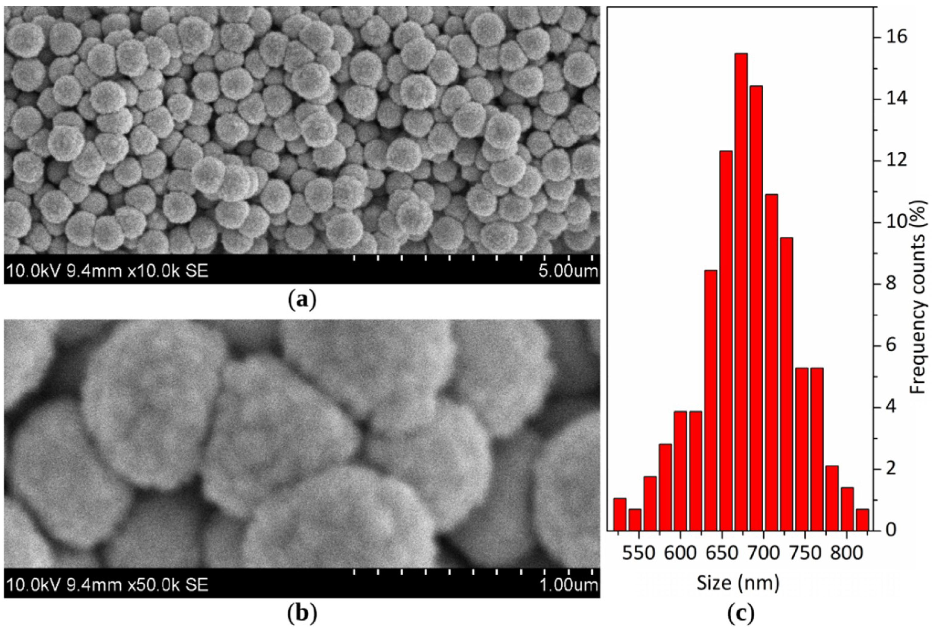
Figure 1. (a) SEM image of sol-gel prepared SiO2–F powder with (b) a detailed view on FOTS-functionalized cauliflower-like silica spheres and (c) histogram of particle size distribution based on SEM imaging.
Coatings 09 00829 g001
Figure 2. (a) TEM images of sol-gel prepared SiO2–F spheres surrounded by cloud-like FOTS structures (outer sheath) with (b) detailed views on silica sphere edge with no distinction between outer and inner sheaths and (c) the edge of silica sphere containing FOTS nanolayer (inner sheath).
Coatings 09 00829 g002
Figure 3. (a) SEM image of SiO2–F spheres with EDX distribution of elements for (b) F Kα signal overlaid with SEM image and (c) overlaid Si Kα, O Kα and F Kα signals, accelerating voltage 18.0 kV.
Coatings 09 00829 g003
Figure 4. (a) SEM image of SiO2–F sphere with (b) EDX line scanning profile obtained along the cross-section of a silica sphere with a diameter of about 720 nm. The white line represents the scan position.
Coatings 09 00829 g004
Figure 5. (a) DSC/TG curves of SiO2–F powder (b) and the first derivative of mass plot accompanied by the repeated TG curve, at a heating rate of 5 K·min−1.
Coatings 09 00829 g005
Figure 6. (a,b) SEM images of general view on SiO2–F coating sprayed on an alumina substrate. Additional SEM images presenting the differences between sandblasted substrate before spraying and the state after spraying are shown in Figure S3.
Coatings 09 00829 g006
Figure 7. (a) SEM image of detailed view on SiO2–F coating sprayed on alumina substrate with an insight on (b) a-zone in valleys (red label) and (c) b-zone in plateaus (blue label) with arrow-marked spherical imprints. Additional SEM images presenting the differences between sandblasted substrate before spraying and the state after spraying are shown in Figure S3.
Coatings 09 00829 g007
Figure 8. (a) SEM image of SiO2–F coating with EDX distribution of elements for (b) Al Kα signal, (c) F Kα signal, (d) C Kα signal, (e) Si Kα signal and (f) O Kα signal, accelerating voltage 10 kV.
Coatings 09 00829 g008
Figure 9. Wettability of SiO2–F coating sprayed on alumina substrate as a measure of contact angle after durability test being: (a) abrasive wear test on 800-grid sandpaper, (b) heat treatment in 2-h annealing cycles, (c) immersion in water and absolute alcohol and (d) ultrasonic bath treatment in absolute alcohol. The dashed line represents the superhydrophobic limit for CA being 150°.
Coatings 09 00829 g009
Figure 10. (a,b) SEM images of general view on SiO2–F coating sprayed on an alumina substrate after abrasive wear test on 5.55 m with red arrows indicating the direction of sliding over sandpaper. Additional SEM images presenting the differences between the as-prepared state and the state after the abrasion test are shown in Figure S4.
Coatings 09 00829 g010
Figure 11. (a) SEM image of detailed view on SiO2–F coatings sprayed on an alumina substrate after annealing at 500 °C in a single 2 h cycle with insight on (b) a-zone in valleys (red label) and (c) b-zone in plateaus (blue label) with distinct arrow-marked spherical imprints. Additional SEM images presenting the differences between the as-prepared state and the state after the thermal treatment are presented in Figure S5.
Coatings 09 00829 g011