Article

Enhancement of Tribological Behavior of Rolling Bearings by Applying a Multilayer ZrN/ZrCN Coating

1
Department of Mechanical Engineering, University of Zaragoza EINA, Maria de Luna 3, 50018 Zaragoza, Spain
2
FERSA BEARINGS S.A., Bari 18, 50197 Zaragoza, Spain
3
AITIIP Foundation, Calle Romero 12, 50720 Zaragoza, Spain
4
Fundación Tekniker, Calle Iñaki Goenaga 5, 20600 Eibar, Spain
*
Author to whom correspondence should be addressed.
Coatings 2019, 9(7), 434; https://doi.org/10.3390/coatings9070434
Submission received: 14 May 2019 / Revised: 4 July 2019 / Accepted: 8 July 2019 / Published: 10 July 2019

Abstract

:
This paper focuses on the tribological behaviour of ZrN/ZrCN coating on bearing steel substrates DIN 17230, 100Cr6/1.3505. Coatings are applied at room temperature processes by means of Cathodic Arc Evaporation (CAE), a kind of Physical Vapor Deposition (PVD) technique. In order to achieve a satisfactory compromise between coating-substrate adhesion and the surface roughness requirement of the bearing rings, a polish post-processing is proposed. Different polish post-processing times and conditions are applied. The coated and polished bearing rings are tested under real friction torque test protocols. These tests show that the application of the coating does not entail a significant improvement in friction performance of the bearing. However, fatigue tests in real test bench are pending to evaluate the possible improvement in bearing life time.

1. Introduction

Roller bearings are components with numerous uses for rotating applications, particularly in the automotive industry. According to recent studies [1], for every liter of fuel used in an average vehicle, 5% is consumed in mechanical losses, and 1% of the total is lost in the simple operation of the bearings. Energy efficiency, the reduction of fuel consumption, and polluting emissions are aspects increasingly demanded. This trend is observed with the emergence of more efficient products, which may even differ from the standard versions in terms of dimensions, assembly, or new materials [2,3].
Despite the aforementioned bearing losses, these mechanical components exhibit very low friction in lubricated conditions (friction coefficient < 0.05), also provided by the rectangular shaped “line contact” among the roller, and the outer and inner rings [4,5,6,7]. The contact pressures may vary from 0.5 up to 3 GPa, depending on the application [4,5]. The rolling operation follows the elastohydrodynamic (EHD) theory, and it is characterized by the thickness of the lubricant film formed during the rolling [8,9,10,11]. Important factors defining the conditions of rolling operation are the surface roughness of the counterparts, [12] and the stress distribution on the subsurface (from 50 to 150 µm underneath the surface) resulting from the contact between the counterparts [13,14,15,16]. Therefore, nowadays, it is commonly expected that tribology can lead to the following technical considerations: improvements of the fuel consumption efficiency through friction reduction; lightweight construction; downsizing of some components through a resistance increase leading to higher Hertzian contact pressures; waste reduction due to a lower wear and less frequent oil changes; as well as the use of more environment-friendly lubricants (Bio-no-tox).
There are different methods for reducing friction on bearings. They go from updating internal bearing geometry or changing bearing component materials (e.g., plastic cages made of nano-additivated plastics to achieve a self-lubricant behavior) [17], to the development of new lubricants or coatings for the rolling bearing surface.
Thin coatings are nowadays an interesting and low-cost approach for solving technical problems since their properties can be highly varied and combined without implying a complete change of the original conception of mechanical components. The deposition of a protective low friction coating on the surface of the rollers extends the lifetime of the component [4,18,19,20]. In many cases, where a coating is deposited on a steel component, the lifetime of the component is increased, and its tribological response improved [21,22,23,24,25]. The overall performance of the coated surfaces is also determined by the coating/substrate interface tolerance to crack propagation [18,21]. It has been demonstrated that coatings produced by physical vapor deposition (PVD) may withstand higher shear stress levels during the rolling phase than coatings produced by chemical vapor deposition (CVD) or thermal spray [20,21,22,23,24,25,26,27]. TiN, TiAlN, TiC, CrN, Cu, and diamond-like carbon (DLC) coatings, produced by PVD [28,29,30,31], have already been studied in rolling-contact fatigue (RCF) tests improving the lifetime of the components [21,22,23,32,33,34]. DLC and carbon nitride (CN) coatings are considered good candidates for its use in rolling components as they provide low friction and high wearing resistance [35,36,37].
In this study, Zr(C, N) thin coatings are considered because they have been successfully tested at a lubricant temperature of 120 °C and, thus reach average Hertzian pressures of 1.94 GPa [38]. From these results, this composition arises as a promising coating to be used in bearings for the automotive industries (differential applications) because they withstand similar working temperatures and contact stresses. Hardly any previous studies have been carried out with the combination of ZrCN coating on bearings. In Kuhn et al. [19], ZrC and ZrN are used for rolling bearings, but the results measured are more focused on the properties of the bearing material than on the functional results such as friction torque, as revealed in this paper.

2. Materials and Methods

2.1. Materials

2.1.1. Substrate

Bearing steel 100Cr6 (according to ISO 683-17 [39]) has been used as a PVD substrate. In this study, a through hardened bearing steel with the following chemical composition was used: carbon (0.93–1.05%), manganese (0.25–1.20%), chromium (0.90–1.60%), molybdenum (0–0.10%), nickel (0–0.25%), and Fe (95.75–97.92%) to balance. Other residuals are: oxygen (max. 10–15 ppm), aluminum (max. 0.050%), titanium (max. 30–50 ppm), and calcium (max. 10 ppm) [40].
Due to its endurance strength, the distribution must compensate an equivalent stress level and, therefore, steel has to be subjected to a martensitic transformation through a hardening treatment, adjusting the hardness of the surface to 59–63 HRC (Rockwell Hardness C scale) at a temperature of 180–200 °C. These HRC values are minimum for a dynamic capacity of 100%.

2.1.2. Bearing Samples

Tapered roller bearing (TRB) 594A/592A belonging to the TRB inches family from FERSA BEARINGS SA (Zaragoza, Spain) and used for differential applications in heavy-duty vehicles was chosen as the sample to be coated. Shape and dimensions are shown in Table 1. Coated surfaces are the contact surfaces between Components 2 and 3 in Figure 1.

2.1.3. Coating Layer

Materials used for the coating layer deposition were Zr target from Robeko (Šibenik, Croatia), purity R60702 ≥ 99.5 wt%; and Ti target from Robeko, purity grade 2, 99.5% in weight. Hydrogen in Argon (20%); Alphagaz 2 Argon (purity ≥ 99.9999 mol%); Alphagaz 2 Nitrogen (purity ≥ 99.9999 mol%), and Alphagaz 1 Acetylene (purity ≥ 99.6 mol%) from Air Liquide (Paris, France) were used as reactive gases.

2.2. Equipment and Experimental

2.2.1. PVD Coating Process

The process was carried out with an industrial equipment MIDAS 775 designed and manufactured by Tekniker (Eibar, Spain) [41]; including a vacuum chamber, 12 circular arc evaporators in four columns; a pulsed DC bias power supply system, consisting of two MDX II DC and one SPARC-VS pulsing unit from Advanced Energy (Fort Collins, CO, USA). Table 1 summarizes the technical data of the equipment.
ZrCN coatings were deposited by a physical vapor deposition (PVD) technique using the cathodic arc evaporation (CAE) method to apply titanium-zirconium-based coatings on the rolling bearing surface. CAE method consists of applying a low voltage and a high current between an anode and an arc cathode in the presence of argon gas in a vacuum chamber, melting or evaporating tiny quantities of material. Approximately 90% of the evaporated cathode particles form positively charged metal ions. A negative bias voltage was then applied between the vacuum chamber and the substrate. This accelerates the metal ions in the direction of the sample surface. A reaction between metal ions and a reactive gas (nitrogen and hydrocarbon) fed in externally was produced, leading to the deposition of the ions on the sample as a fine carbonitride layer.
Prior to PVD deposition, the sample substrates were cleaned in a degreasing-solvent sequence. Once loaded in the vacuum chamber, it was evacuated up to a pressure of 10−4 mbar. Then, a Glow Discharge cleanliness stage was implemented. It consists of applying a current of 4 A under vacuum conditions (0.4 mbar) on the samples in an atmosphere of argon mixed with hydrogen (140 sccm) during 30 min. Subsequently, a high negative bias step to promote adhesion was introduced. A voltage of −600 V was applied to the samples in an argon atmosphere (100 sccm) with two Ti arcs at 120 A.
After the cleanliness stage, four different PVD coating designs were developed by using 4 metallic evaporators (2Ti, 2Zr), and introducing Nitrogen gas (N2, 300 sccm) and acetylene (C2H2, 10–20 sccm) in a reactive process (pressure 10−2 mbar). 400 V of Bias voltage was initially applied, decreasing gradually to 30 V in 4 min, voltage which was maintained during the rest of the process. The arc intensity of Titanium and Zirconium targets during the growing steps was set at 120 and 140 A, respectively. As it is described in Table 2, each coating design consists of a first adhesion layer followed by the functional coating multilayer. A first robust thick Ti metallic layer followed by a Ti–Zr transition was applied as an adhesion layer in D1. A thinner adhesion sequence (Ti + Ti–Zr) was performed for D2 and, in D3, after a very brief Ti metallic step, nitrogen was introduced followed by the last step including Zr.
Regarding the functional coating, a multilayer was deposited consisting of three ZrN/ZrCN bilayer sequences (10/5 min, respectively) for D1, D2, and D3. In D4, a fourth identical bilayer was added. The different adhesion sequences were designed to guarantee a proper substrate-coating adhesion. The functional multilayer was designed to provide the tribological properties required to reduce friction during the bearing performance.

2.2.2. Polish Post-Processing

A polish post-processing stage was carried out on those coated bearings samples with Ra values exceeding the bearing specifications (Ra < 0.15 µm). Two different methods were followed. Method A used the walnut shell (0.2–0.4 mm) as an abrasive material in an OTEC DF 35 machine (OTEC Präzisionsfinish GmbH, Straubenhardt-Conweiler, Germany), which is a spindle abrasive finishing machine, with 3 workplace holders, 0.75 kW, and a 230 volt motor with octagonal stainless-steel process container and controls. Method B used the walnut shell (0.8–1.7 mm) additivated with a silica base abrasive (80%) in a Pardus Drag Finish Unit from PD2i machine (Paris, France). In both types of equipment, samples were introduced in a vessel full of abrasive material in order to polish the surface of the piece. Method A was defined by applying 30 min steps (15 min each way) at 20 rpm; and Method B was characterized by applying 15 min (1.5 min each way) at 35 rpm. Three different configurations were employed according to Table 3.

2.2.3. Geometric Analysis

Before testing coating quality parameters, a complete metrological analysis including shapes, profiles, and roundness of bearing raceway and flange is done. Profile characterization is carried out by using a Form Talysurf 120 (Taylor Hobson Ibérica, Barcelona, Spain). This analysis is crucial to know if coated bearing samples to be tested are comparable to the baseline design bearing according to the allowed limits and shapes agreed by FERSA BEARINGS SA (Zaragoza, Spain). Figure 2 shows the inner ring raceway profile (a), and the flange profile (b) where the geometric analysis is performed.
A second test testing the roundness of the raceway is performed according to ISO 1101:2017 [42] with a Talyrond 365 with software Ultra by Taylor Hobson V5.21.9.36, both from TAYLOR HOBSON (Taylor Hobson Ibérica, Barcelona, Spain). Roundness (RONt) is defined as the separation of two concentric circles that enclose the circular section of interest, that is, the circular raceway section in this study. An accurate roundness measurement is vital to ensure the correct function of the bearings avoiding noise and premature failures.

2.2.4. Hardness

A durometer ERGOTEST DIGI 25 R (LFT, Antegnate, Italy) was used to perform an HRC test on the samples before and after applying a PVD coating according to S/UNE-EN ISO 6508-1 [43]. The indentation force was 1471 N with a preload of 98 N, and the diamond indentation angle was 120°. This test has the purpose of verifying that the hardness of the substrate surface was kept within the 59–63 HRC range after the PVD deposition process. In case the coating detaches during the bearing performance, the substrate must keep its initial properties and performance conditions of a standard bearing without coating. Initial properties of the substrate could be altered by the increase of temperature on the substrate due to PVD deposition process, which could lead to a hardness decreasing on the substrate.

2.2.5. Coating Properties

Coating properties measured to ensure its validity are roughness (Ra), thickness, adhesion, and bearing friction torque.
  • Roughness
Perthometer M2 from Mahr (Barcelona, Spain), with a maximum range of 150 µm and a maximum cut-off length of 17.5 mm, was used for measuring roughness of coated samples as Ra (arithmetical mean deviation of the assessed profile), used in standards such as DIN EN ISO 4287:1998 [44], or JIS B 0601:1994 [45]. This equipment uses a mapping method for a 2D surface analysis in which a surface is horizontally crossed at a constant speed. The mapping profile is the superficial profile drawn with an analysis needle (ø 2 µm). Quantification is made by measuring the vertical deviations of a real surface compared to its ideal shape. The cut-off parameter is a profile filter that sets which wavelength refers to roughness and which one to waviness. Cut-off parameters set for the tests according to Ra ranges are shown in Table 4. To ensure a proper bearing performance, the arithmetical mean deviation of the assessed profile roughness (Ra) must be lower than 0.15 μm according to FERSA BEARINGS SA specifications.
Coating surface, as well as cross sections, were analyzed via scanning with an electron microscopy High Resolution FE-SEM Ultra Plus, Zeiss(Oberkochen, Germany).
  • Thickness
Coating thickness was determined using a Calostest Test with a Calotest CSEM equipment (DEPHIS, Étupes, France). A ball was turned over the coating until it arrived at the substrate, producing a spherical crater. Microscope measuring of this dimple diameter allows us to know the coating thickness [47]. An adequate thickness measurement ranges between 1 and 10 µm, given that a smaller thickness dimple could be too small, leading to inaccurate measurements.
  • Adhesion
A Rockwell C indentation was performed with a durometer WIZHARD HR-522 (Mitutoyo, Kanagawa, Japan) with a load of 1470 N, then trace edges were analyzed with an optical microscope to evaluate adhesion. A chart VDI, Verein Deutscher Ingenieure Normen 3198 indentation test (Figure 3) was used to set the adhesion grade [48]. The chart states that the bigger the crack and delamination number, the worse the adhesion. Values from HF1 to HF4 stand for acceptable adhesion values, and HF5 and HF6 values stand for non-acceptable adhesion values.
  • Coating composition
The profiles of composition in coating depth were analyzed with the Glow Discharge Optical Emission Spectrometry (GD-OES) equipment from Horiba Jobin YvonSAS (Palaiseau, France). The equipment analyzes the emitted light by the atoms sputtered from the sample; each one producing a light emission at a characteristic wavelength. The measurement conditions used were 650 Pa and 35 W, with a copper anode of 4 mm of diameter [49]. For this characterization, coatings deposited on stainless steel (AISI 430) were employed.
  • Coating structure
The crystal structure of the films was examined by a grazing-incidence X-ray diffraction (XRD) using an angle of 2° and Cu Kα radiation in a Bruker D8 Advance diffractometer with Bragg-Brentano beam geometry. A step size of 0.02 (2θ) with 2.5 s per point was used.
X-ray diffraction is based on a constructive interference of monochromatic X-rays and a crystalline sample. The interaction of the incident rays with the sample produces a constructive interference (and a diffracted ray) when conditions satisfy Bragg’s Law (nλ = 2dsinθ). This law relates the wavelength of electromagnetic radiation to the diffraction angle and the lattice spacing in a crystalline sample.

2.2.6. Friction Torque

Two friction torque test protocols, described in Table 5, were performed to know the behavior of bearings samples under both low-load and low-speed conditions. The Stribeck test (ST) determines friction torque at low loads, and it is useful to determine how the lubrication regime is acting, and how much torque bearing is consuming during the running-in. The Torque to Rotate (TTR) test was used to determine how much torque the bearing consumes under different loads and at a low speed. They both offer a GO/NO GO threshold to check if the ZrN/ZrCN coatings peel-off, or they stay on the bearings surface during their lifetime. Three coated bearing pairs, named as Set 1, Set 2 and Set 3, plus a pair of uncoated bearings, named as baseline, were subjected to the tests. Friction torque tests were carried out in collaboration with FERSA BEARINGS SA in an AX-180 TT test rig where tapered roller bearings were assembled in a tandem configuration. Protective oil Shell Ensis RPO 1000 (kinematic viscosity 35 Cst, flash point 192 °C, specific gravity 0.899 g/cm3) was applied as the bearing lubrication. The test rig characteristics were: test bench size, 450 mm × 1220 mm; No. of stations, 1; No. of bearings, 2; bearing outer diameter size, up to 180 mm; axial load (max.) 15 kN; speed range, 0–1000 rpm; and torque (max.) 100 Nm.

3. Results and Discussion

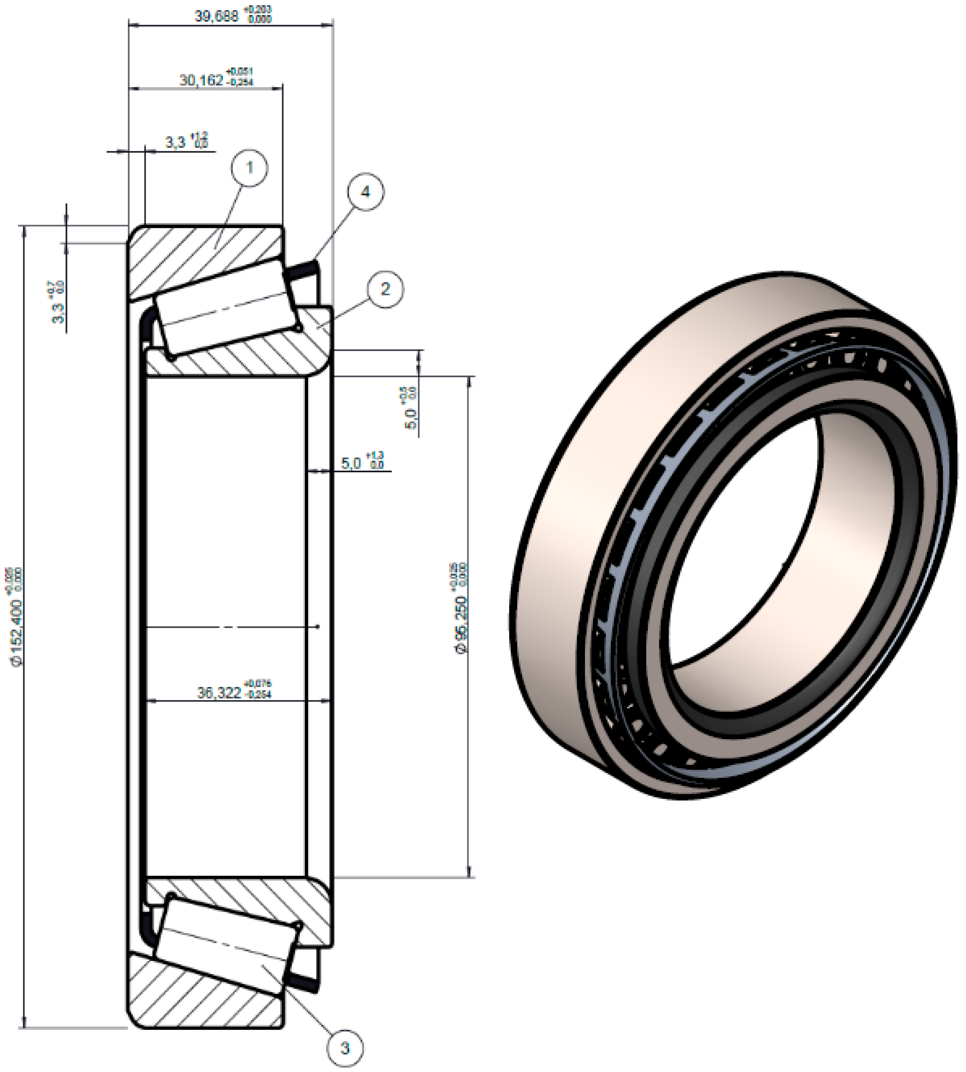
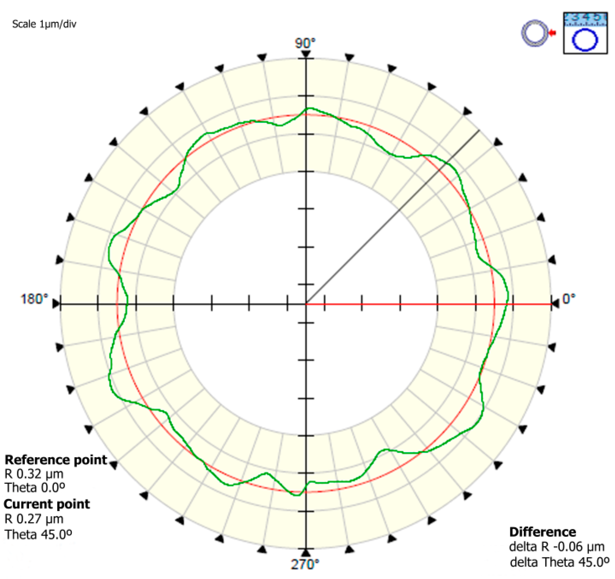
3.1. Geometrical Analysis

Results of a geometrical analysis for the raceway profile defined as (a) in Figure 2 are shown in Figure 4. Although all the samples were tested, Figure 4 and Figure 5 only show the results for D4 coating, since the results for all the configurations of the coating were very similar. Figure 4a shows a raceway profile for uncoated bearings, and Figure 4c shows a raceway profile for coated bearings. It can be observed that the coating has perfectly copied the shape of the raceway logarithmic profile. Figure 4b,d show the roughness of the profile along the dotted area in Figure 4a,c. Roughness is represented on a horizontal axis (different from the axis of the bearing profile) in order to calculate an average of the peaks and valleys, and, thus, the roughness. It is also confirmed in detailed views that the coating reproduces almost exactly the uncoated track.
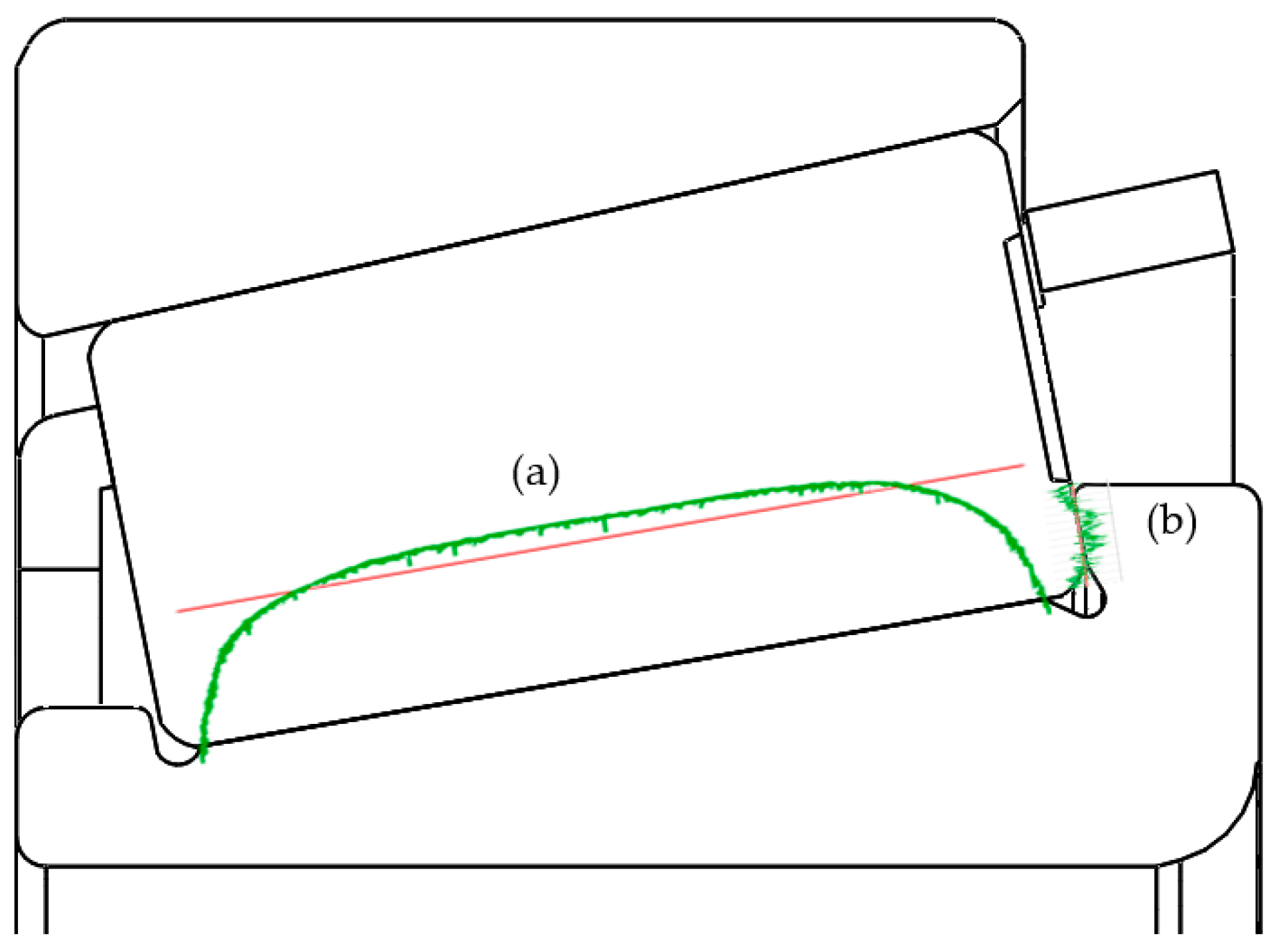
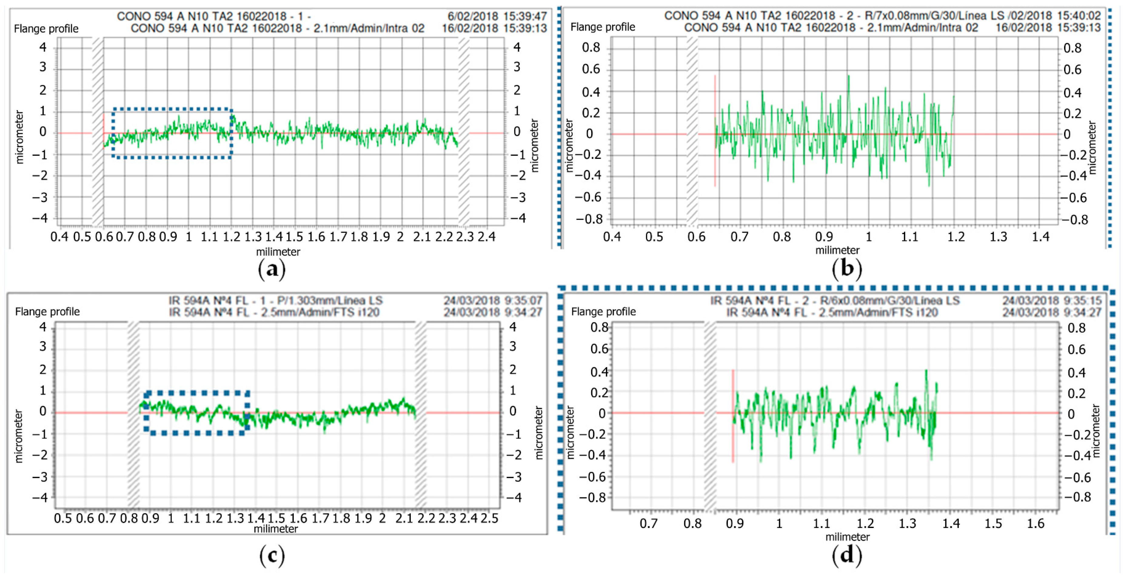
The results of a geometrical analysis for flange profile, which is defined as (b) in Figure 2 are shown in Figure 5. Figure 5a shows the flange profile for uncoated bearings, and Figure 5c shows the flange profile for coated bearings. It can be observed that the coating has also perfectly copied the shape of the flange profile. Figure 5b,d show the roughness of the profile along the dotted area in Figure 5a,c. Roughness is represented on a horizontal axis (different from the axis of the bearing profile) in order to calculate an average of the peaks and valleys, and thus the roughness. It is also confirmed in detailed views that the coating reproduces almost exactly the uncoated flange.
Figure 6 shows the RONt distribution at the inner ring raceway. RONt values, obtained after the PVD coating process, range from 0.82 to 2.34 μm, which are under the FERSA BEARINGS SA specifications (RONt < 6 μm).
It can be concluded that the obtained shapes are suitable according to FERSA BEARINGS SA specification, so the coating process has no affection on the profile shapes of the bearing. Therefore, it allows proceeding with the roughness, thickness, hardness, and adhesion tests ensuring that the results obtained are comparable to those obtained on the uncoated baseline bearings.

3.2. PVD Coating Characterization

The Zr(C,N) coatings were analyzed by means of XRD, using the Cu K_1 wavelength (0.154075 nm). The corresponding spectrum is represented in Figure 7. Graze Incidence X-Ray Diffraction (GIXRD) was employed, meaning that, as the functional coating is the same for all the studied coating designs, equivalent spectra are obtained in all the cases. That is the reason just one of them is shown.
The spectrum agrees with an equivalent coating reported in a previous work [38], showing clear peaks of cubic Zr2CN, cubic ZrN, and ZrC, approximately homologous. The coatings investigated are crystalline with a rock salt like a NaCl cubic structure Fm–3m.
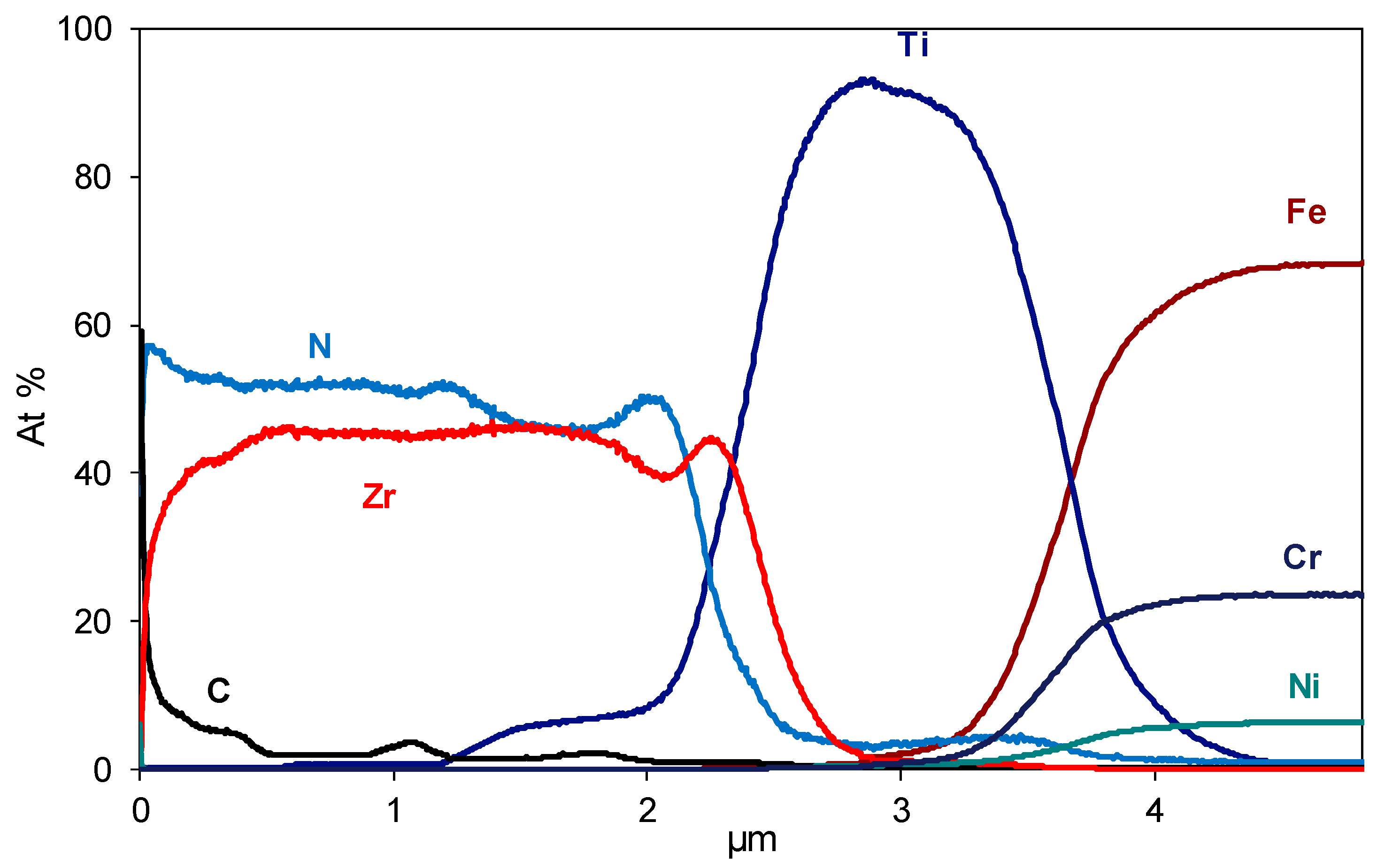
The chemical composition profiles of the developed coatings were measured using the GD-OES technique. Figure 8 shows the profile corresponding to D1 design as an example, where the sequence of the adhesion layer and functional layer configuration can be observed. It must be said that the profile gives a qualitative idea of the progression in chemical composition in coating depth because a general PVD method for calibration has been used. On the right of the graph, the main elements of the stainless-steel substrate can be seen, and afterward an increase of the titanium concentration is appreciated due to the first titanium adhesion layer. Finally, regarding the functional layer, the sequence of three ZrN/ZrCN bilayers can be observed by the presence of small “hills” for carbon profile, which correspond to the introduction of acetylene gas during the coating deposition process.
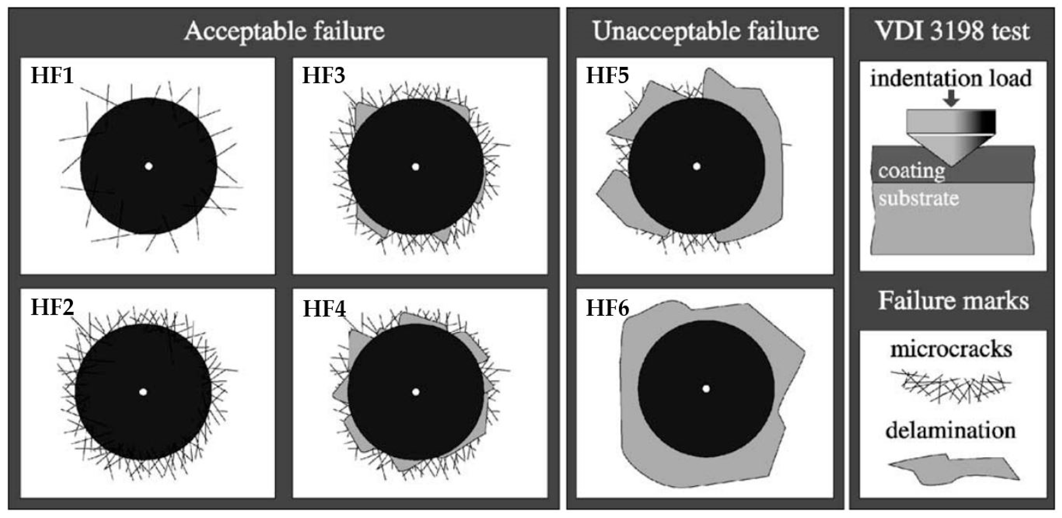
Table 6 gathers the characterization results obtained for the developed coatings, regarding roughness, thickness, adhesion, and substrate integrity.
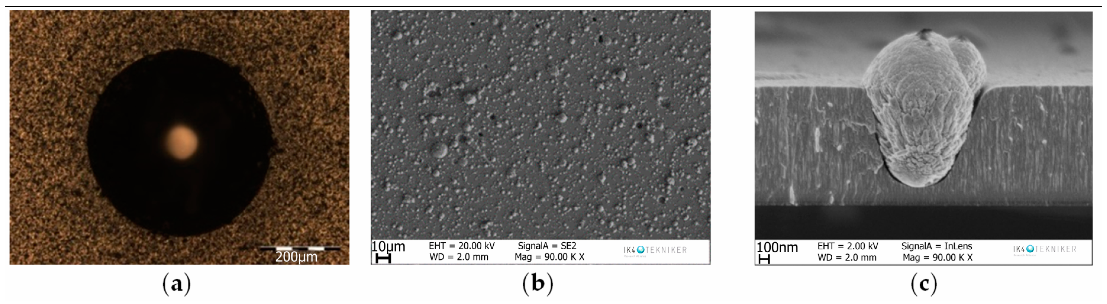
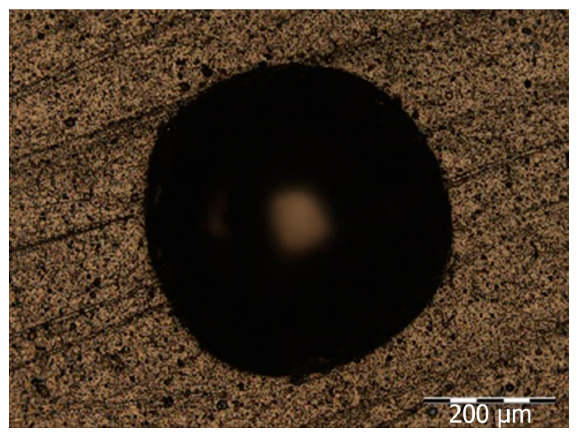
Coating design D1 offers a good adhesion result HF1, showing neither cracks nor delamination (Figure 9a). Nevertheless, the roughness Ra is 0.540 μm, above the allowed value (Ra < 0.15 μm) due to the presence of droplets. These droplets are inherent to the Arc Evaporation coating technology in which a very high grade of ionization is achieved. At the same time, these high energies can melt the material to be deposited, with the formation and deposition of the consequent droplets. Filters can be used (Filtered Arc Evaporation) to avoid droplets reaching the substrate but, as this variant entails lower deposition rates, it was not considered interesting from an industrial point of view. As can be seen in the cross-section of the adhesion layer (Ti + Ti–Zr) of the D1 coating (Figure 9b,c), the Ti metallic first layer is the main responsible for the high roughness, reason why a strategy to reduce the thickness (1.24 μm) of this adhesion layer is followed in D2 and D3 coating designs.
For the coating design D2, 5 min of Ti instead of 60 min, and 1 min of Ti–Zr instead of 5 min have been applied. An evident lack of adhesion (HF5) is observed. Figure 10a shows grey zones surrounding the indentation, which correspond to the bare substrate, areas where the coating has been detached. Roughness (Ra = 0.240 μm) has been reduced (Figure 10b), although it is not low enough to enter under the specifications. Therefore, applying a thinner adhesion layer (0.21 μm) leads to a lower roughness at the expense of the substrate-coating adhesion.
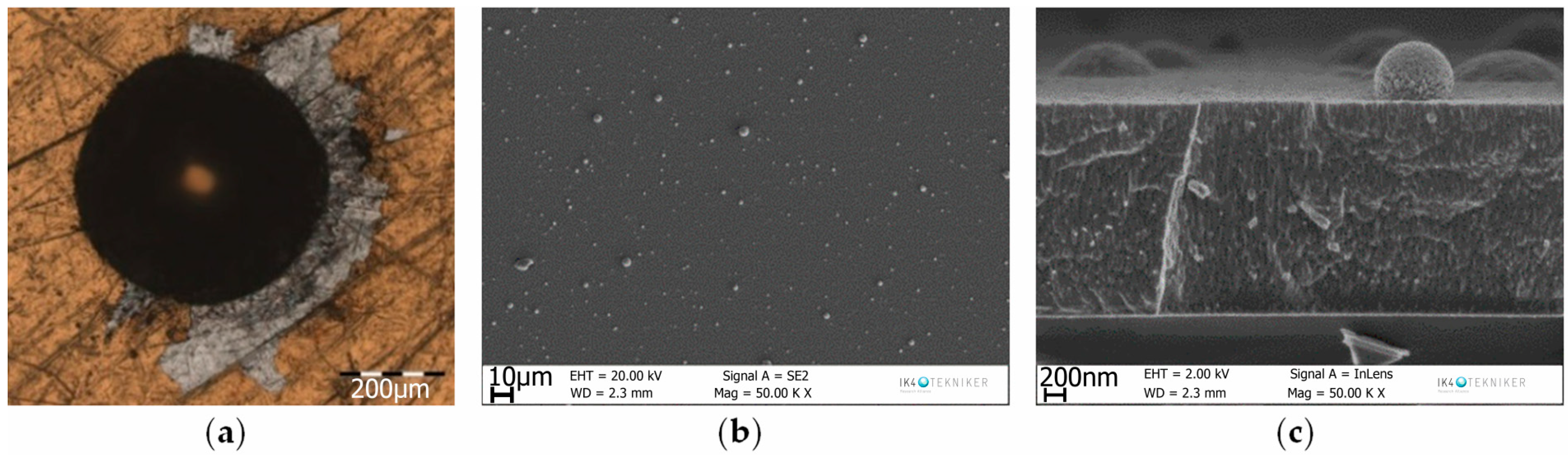
D3 coating design includes a new structure for the adhesion layer. After a thinner Ti metallic layer of one minute (to reduce roughness), nitrogen is introduced (4 min) before Zr, trying to build a more progressive transition to the functional multilayer starting with ZrN, with the aim of providing the coating an improved adhesion (total thickness of adhesion layer 0.46 μm). A proper Ra value of 0.080 μm is achieved, which can be observed in both the surface and cross-section micrographs (Figure 11b,c), where a lower density and smaller droplets appear. However, once again, the coating results in a lack of adhesion HF5 (Figure 11a).
The D1 structure was reconsidered for the D4 design. However, taking into account the subsequent polish post-processing to be applied for roughness reduction, a fourth ZrN/ZrCN bilayer was added to the functional coating, achieving an adhesion layer thickness of 1.23 μm similar to the D1 adhesion layer, and a total thickness of 4.33 μm. Therefore, the thickness of the functional coating is increased to compensate for the thickness reduction during the polish post-processing. HF1 classification is observed at the adhesion test, as it can be seen in Figure 12, where neither trace of peeling off nor bare substrates are observed. As expected, the roughness of the deposited coating (Ra 0.533 µm) is far from the allowed roughness of 0.15 μm.

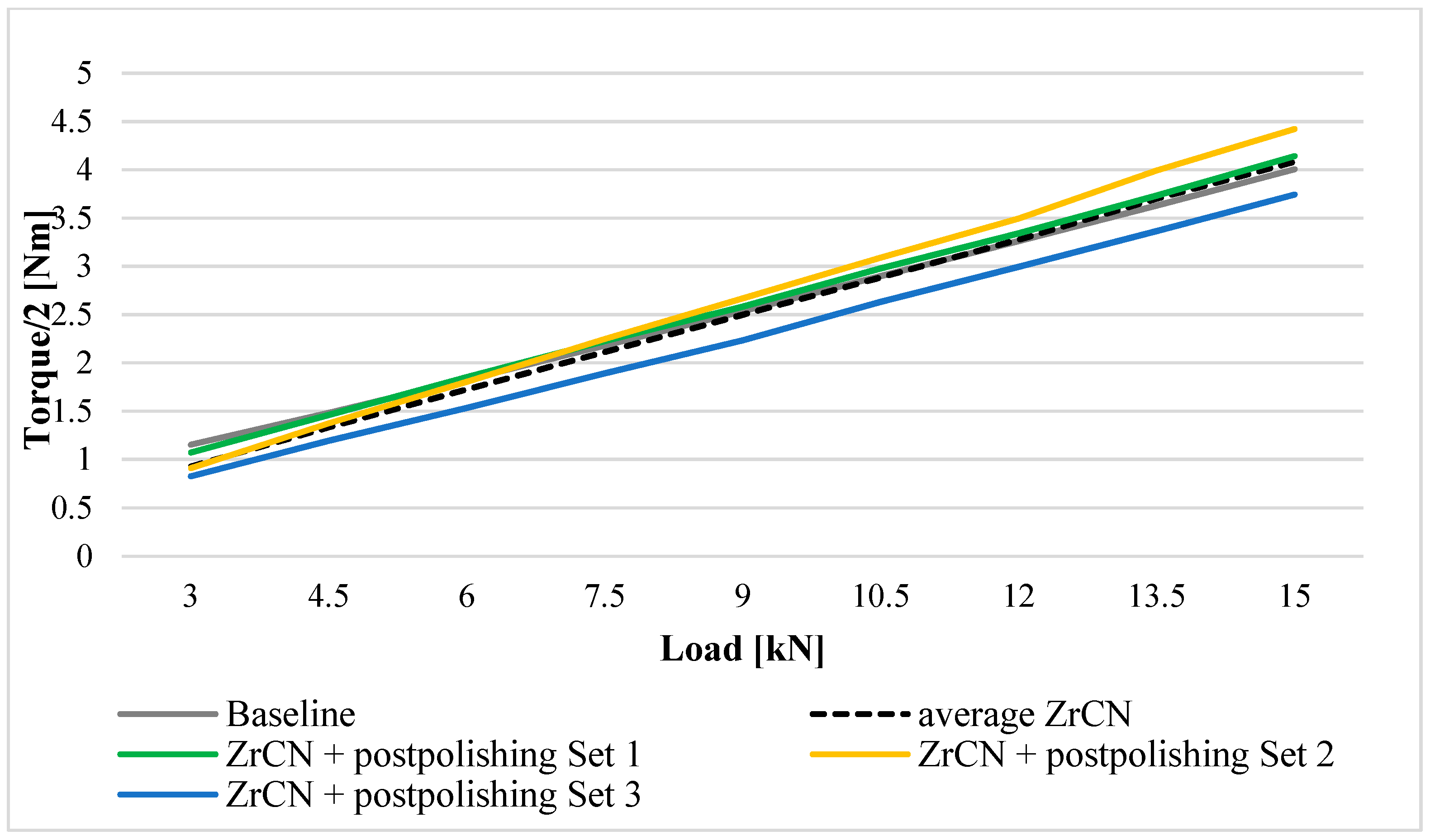
3.3. Polish Post-Processing

After the analysis of the PVD process carried out at a low-temperature Arc Evaporation, it can be concluded that coating design strategies are not enough to get a proper coating balancing required in terms of roughness and adhesion results. For that reason, a polish post-processing is applied to decrease the surface roughness of the properly adhered coatings D1 and D4. Table 7 shows roughness results after the polish post-processing.
After applying the polish post-processing Method A during three hours (Polish Configuration A1), samples D1 were measured and then, introduced again in the vessel to continue the polish post-processing up to six hours (Polish Configuration A2). Ra values decrease by 31.30% for Configuration A1 and by 58.15% for Configuration A2, showing that Configuration A is not able to obtain the required roughness. Following the more aggressive polish post-processing Method B (Configuration B), Ra is reduced by 68.33% up to 0.171 μm in 15 min, achieving an adhesion very close to the roughness specification. In case of the D4 coating design, since a fourth Zr/ZrCN bilayer was added, the final thickness after polish post-processing is not significantly changed, and Ra is reduced by 72.33% up to 0.148 μm (< Ra = 0.15 required). 
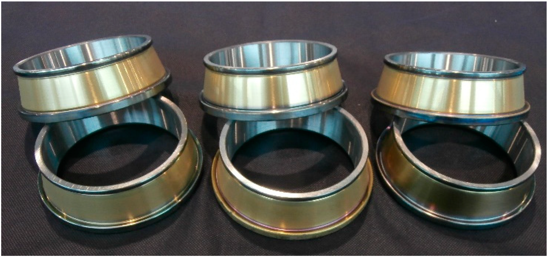
Figure 13 shows D4 coated samples, post polished under Configuration B.

3.4. Substrate Hardness

HRC on the bearing substrate, before and after the PVD application, is shown in Table 6. Samples before the PVD application show an HRC value around 60 HRC. After the PVD application, they decrease up to values ranging from 59 to 59.7 HRC. The reduction in HRC when applying the PVD process is explained by the increasing temperature on the sample during the cathodic arc application on the bearing steel. This analysis of the hardness of the sample gives relevant information about the performance of bearing steel after a PVD process implementation. HRC values ranging 59–63 HRC after the PVD application indicate that the steel of the bearing sample has not reached 180–200 °C, which is the tempering temperature of the bearing steel, avoiding any deterioration of the substrate properties. Figure 14a shows that the tempering temperature is achieved at 180–200 °C for martensitic bearing steel. Figure 14b gives information about the relation between the tempering temperature and the HRC hardness for martensitic bearing steel. It can be observed that the temperature range of 180–200 °C corresponds to a range of 59–63 HRC [50].

3.5. Friction Torque

Samples with the D4 coating design and the Configuration B polish post-processing, achieving functional requirements of Ra, thickness, hardness, and adhesion, were subjected to friction torque results in order to test if any improvement is achieved in the bearing performance.

3.5.1. Stribeck Tests

Stribeck tests results are shown in Figure 15. At the beginning of the test, the four sets of samples, Set 1, Set 2, Set 3, and baseline reach the initial torque values between 6 and 6.5 Nm. Then, during stabilization, Set 1 torque stabilizes at around 4 Nm, Set 2 torque stabilizes at 3.2 Nm, and Set 3 torque stabilizes at 3 Nm. However, the baseline sample stabilizes at 1.3 Nm, which is a very promising result, much better than the coated and polished bearings. Therefore, as can be checked, the friction of the coated bearings is never lower than the friction consumed by uncoated bearings, so there is no improvement in the tribological behavior of the bearings after coating them at low-load conditions.

3.5.2. TTR Tests

Figure 16 shows the results for TTR tests. It can be observed that the friction behavior is similar for all the bearing samples (Set 1, Set 2, Set 3, baseline) at low speed and loads. However, slight differences can be observed at high loads, where Set 3 achieves torque values lower than the baseline torque.
Analyzing torque vs load in Figure 17, it is shown that Set 3 exhibits a lower torque value than the baseline for all the loads, which is not achieved for Set 1 and Set 2. The dotted line shows the average torque value for the three sets of coated bearings, which confirms that the behavior is quite constant between the samples, and no major torque improvement appears regarding baseline torque.

4. Conclusions

A strategy based on applying PVD coatings on rolling bearings is proposed in order to improve friction behavior during the bearing performance. Different PVD coating designs have been tested varying mainly the adhesion layer. Coatings with thick interlayer show good adhesion results, although the roughness specification is not achieved. Only samples coated with a thin interlayer of Ti–TiN obtain acceptable roughness values, but at the expense of an inadequate adhesion. A polish post-processing is proposed for the samples with suitable adhesion in order to reduce roughness. The method based on walnut shell additivated with an 80% abrasive silica achieves the required low roughness. Coated rolling bearings are subjected to a friction torque test to evaluate their tribological behavior. However, regarding tribological properties of the coated rolling bearings, hardly any improvement is observed in the friction torque neither at low load nor at low speed. However, fatigue tests in real test bench are pending to evaluate the possible improvement in bearing life time.

Author Contributions

Conceptualization, I.C., C.Z. and G.M.; Data curation, C.Z. and G.M.; Formal analysis, A.L., Á.F. and P.C.; Funding acquisition, Á.F. and P.C.; Investigation, A.L.; Methodology, C.Z. and G.M.; Project administration, Á.F. and P.C.; Resources, I.C., A.L. and D.E.; Software, G.M.; Supervision, I.C.; Validation, C.Z.; Visualization, D.E.; Writing—original draft, I.C. and A.L.; Writing—review & editing, I.C.

Funding

This research was funded by Spanish Ministry of Industry, Economics and Competitivity (RTC-2016-5799-4) and has been performed by members of the I+AITIIP (DGA-T08_17R) research group of the FEDER 2014-2020 “Building Europe from Aragón” program, recognized by the Regional Government of Aragon.

Conflicts of Interest

The authors declare no conflicts of interest. The founding sponsors had no role in the design of the study; in the collection, analyses, or interpretation of data; in the writing of the manuscript, and in the decision to publish the results.

References

  1. Holmberg, K.; Andersson, P.; Nylund, N.-O.; Mäkelä, K.; Erdemir, A. Global energy consumption due to friction in trucks and buses. Tribol. Int. 2014, 78, 94–114. [Google Scholar] [CrossRef]
  2. Ligier, J.L.; Noel, B. Friction Reduction and Reliability for Engines Bearings. Lubricants 2015, 3, 569–596. [Google Scholar] [CrossRef] [Green Version]
  3. Nirmal, U. Friction Performance of Aged T-BFRP Composite for Bearing Applications. Polymers 2018, 10, 1066. [Google Scholar] [CrossRef] [PubMed]
  4. Holmberg, K.; Matthews, A. Tribology of coatings. In Coatings Tribology: Properties, Mechanisms, Techniques, and Applications in Surface Engineering, 2nd ed.; Elsevier: Amsterdam, The Netherlands, 2009; pp. 41–183. [Google Scholar]
  5. Bhadeshia, H.K.D.H. Steels for bearings. Prog. Mater. Sci. 2012, 57, 268–435. [Google Scholar] [CrossRef]
  6. Dowson, D.; Higginson, G.R. Analysis of roller bearings. In Elasto-Hydrodynamic Lubrication, 1st ed.; Hopkins, D.W., Ed.; Elsevier: Amsterdam, The Netherlands, 1977; pp. 193–215. [Google Scholar]
  7. Dowson, D. Elastohydrodynamic and micro-elastohydrodynamic lubrication. Wear 1995, 190, 125–138. [Google Scholar] [CrossRef]
  8. Dowson, D.; Higginson, G.R. Theory of roller bearing lubrication and deformation. Proc. Inst. Mech. Eng. 1963, 177, 67–69. [Google Scholar]
  9. Harris, T.; Mindel, M. Rolling element bearing dynamics. Wear 1973, 23, 311–337. [Google Scholar] [CrossRef]
  10. Archard, J.F.; Crook, A.W. Apparatus and measurements of film thickness and film shape. In Elasto-Hydrodynamic Lubrication, SI ed.; Dowson, D., Higginson, G.R., Eds.; Pergamon Press: Oxford, UK, 1977; pp. 481–495. [Google Scholar]
  11. Katsaros, K.; Bompos, D.A.; Nikolakopoulos, P.G.; Theodossiades, S. Thermal-Hydrodynamic Behaviour of Coated Pivoted Pad Thrust Bearings: Comparison between Babbitt, PTFE and DLC. Lubricants 2018, 6, 50. [Google Scholar] [CrossRef]
  12. Xie, Z.; Rao, Z.; Liu, H. Effect of Surface Topography and Structural Parameters on the Lubrication Performance of a Water-Lubricated Bearing: Theoretical and Experimental Study. Coatings 2019, 9, 23. [Google Scholar] [CrossRef]
  13. Morales-Espejel, G.E.; Brizmer, V. Micropitting modelling in rolling-sliding contacts: Application to rolling bearings. Tribol. Trans. 2011, 54, 625–643. [Google Scholar] [CrossRef]
  14. Miller, G.R.; Keer, L.M.; Cheng, H.S. On the mechanics of fatigue crack growth due to contact loading. Proc. R. Soc. A 1985, 397, 197–209. [Google Scholar] [CrossRef]
  15. Morales-Espejel, G.; Brizmer, V.; Piras, E. Roughness evolution in mixed lubrication condition due to mild wear. Proc. Inst. Mech. Eng. Part J J. Eng. Tribol. 2015, 229, 1330–1346. [Google Scholar] [CrossRef]
  16. Oh, H.; Azarian, M.H.; Morillo, C.; Pecht, M.; Rhem, E. Failure mechanisms of ball bearings under lightly loaded, non-accelerated usage conditions. Tribol. Int. 2015, 81, 291–299. [Google Scholar] [CrossRef]
  17. Clavería, I.; Elduque, D.; Lostalé, A.; Fernández, A.; Javierre, C.; Castell, P. Analysis of self-lubrication enhancement via PA66 strategies: Texturing and nano-reinforcement with ZrO2 and graphene. Tribol. Int. 2019, 131, 332–342. [Google Scholar] [CrossRef]
  18. Erdemir, A. Rolling-contact fatigue and wear resistance of hard coatings on bearing-steel substrates. Surf. Coat. Technol. 1992, 54, 482–489. [Google Scholar] [CrossRef]
  19. Kuhn, M.; Gold, P.W.; Loos, J. Wear and friction characteristics of PVD-coated roller bearings. Surf. Coat. Technol. 2004, 177, 469–476. [Google Scholar] [CrossRef]
  20. Igartua, A.; Laucirica, J.; Aranzabe, A.; Leyendecker, T.; Lemmer, O.; Erkens, G. Application of low temperature PVD coatings in rolling bearings: Tribological tests and experiences with spindle bearing systems. Surf. Coat. Technol. 1996, 86, 460–466. [Google Scholar] [CrossRef]
  21. Hochman, R.F. Rolling contact fatigue behavior of Cu and TiN coatings on bearing steel substrates. J. Vac. Sci. Technol. A 1985, 3, 2348–2353. [Google Scholar] [CrossRef]
  22. Rosado, L.; Jain, V.K.; Trivedi, H.K. The effect of diamond-like carbon coatings on the rolling fatigue and wear of M50 steel. Wear 1997, 212, 1–6. [Google Scholar] [CrossRef]
  23. Chang, T.-A.P.; Cheng, H.S.; Sproul, W.D. The influence of coating thickness on lubricated rolling contact fatigue life. Surf. Coat. Technol. 1990, 43, 699–708. [Google Scholar] [CrossRef]
  24. Komori, K.; Umehara, N. Effect of surface morphology of diamond-like carbon coating on friction, wear behavior and tribo-chemical reactions under engine oil lubricated condition. Tribol. Int. 2015, 84, 100–109. [Google Scholar] [CrossRef]
  25. Yeo, S.M.; Polycarpou, A.A. Fretting experiments of advanced polymeric coatings and the effect of transfer films on their tribological behavior. Tribol. Int. 2014, 79, 16–25. [Google Scholar] [CrossRef]
  26. Stewart, S.; Ahmed, R. Rolling contact fatigue of surface coatings—A review. Wear 2002, 253, 1132–1144. [Google Scholar] [CrossRef]
  27. Baptista, A.; Silva, F.; Porteiro, J.; Miguez, J.; Pinto, G. Sputtering Physical Vapour Deposition (PVD) Coatings: A Critical Review on Process Improvement and Market Trend Demands. Coatings 2018, 8, 402. [Google Scholar] [CrossRef]
  28. Chen, J.; Geng, M.; Li, Y.; Yang, Z.; Chai, Y.; He, G. Erosion Resistance and Damage Mechanism of TiN/ZrN Nanoscale Multilayer Coating. Coatings 2019, 9, 64. [Google Scholar] [CrossRef]
  29. Geng, M.; He, G.; Sun, Z.; Chen, J.; Yang, Z.; Li, Y. Corrosion Damage Mechanism of TiN/ZrN Nanoscale Multilayer Anti-Erosion Coating. Coatings 2018, 8, 400. [Google Scholar] [CrossRef]
  30. Vereschaka, A.; Kataeva, E.; Sitnikov, N.; Aksenenko, A.; Oganyan, G.; Sotova, C. Influence of Thickness of Multilayered Nano-Structured Coatings Ti–TiN-(TiCrAl)N and Zr-ZrN-(ZrCrNbAl)N on Tool Life of Metal Cutting Tools at Various Cutting Speeds. Coatings 2018, 8, 44. [Google Scholar] [CrossRef]
  31. Zhang, P.; Wang, J. Torsional Fretting Wear Behavior of PVD TiCN Coated CuNiAl Blade Bearing in Oil and Artificial Seawater. Coatings 2019, 9, 140. [Google Scholar] [CrossRef]
  32. Klaffke, D.; Santner, E.; Spaltmann, D.; Woydt, M. Influences on the tribological behaviour of slip-rolling DLC-coatings. Wear 2005, 259, 752–758. [Google Scholar] [CrossRef]
  33. Thom, R.; Moore, L.; Sproul, W.D.; Peter Chang, T. Rolling contact fatigue tests of reactively sputtered nitride coatings of Ti, Zr, Hf, Cr, Mo, Ti–Al, Ti–Zr and Ti–Al–V on 440 C stainless steel substrates. Surf. Coat. Technol. 1993, 62, 423–427. [Google Scholar] [CrossRef]
  34. Novak, R.; Polcar, T. Tribological analysis of thin films by pin-on-disc: Evaluation of friction and wear measurement uncertainty. Tribol. Int. 2014, 74, 154–163. [Google Scholar] [CrossRef]
  35. Grill, A. Tribology of diamondlike carbon and related materials: An updated review. Surf. Coat. Technol. 1997, 94, 507–513. [Google Scholar] [CrossRef]
  36. Robertson, J. Diamond-like amorphous carbon. Mater. Sci. Eng. R Rep. 2002, 37, 129–281. [Google Scholar] [CrossRef] [Green Version]
  37. Fiaschi, G.; Rota, A.; Ballestrazzi, A.; Marchetto, D.; Vezzalini, E.; Valeri, S. A Chemical, Mechanical, and Tribological Analysis of DLC Coatings Deposited by Magnetron Sputtering. Lubricants 2019, 7, 38. [Google Scholar] [CrossRef]
  38. Manier, C.-A.; Ziegele, H.; Barriga, J.; Goikoetxea, J.; Woydt, M. Zirconium-based coatings in highly stressed rolling contacts as alternative solution to DLC and ta-C coatings. Wear 2010, 269, 770–781. [Google Scholar] [CrossRef]
  39. ISO. 683-17:2014 Heat Treated Steels, Alloy Steels and Free-Cutting Steels—Part 17: Ball and Roller Bearing Steels; ISO: Geneva, Switzerland, 2015. [Google Scholar]
  40. Dinkel, M. Bearing Steels and Heat Treatment. In Proceedings of the ABMA Webinar Series, 17 September 2015; Available online: https://www.americanbearings.org/events/EventDetails.aspx?id=654049&hhSearchTerms=%22bearing+steels+and+heat+treatment%22 (accessed on 17 September 2015).
  41. IK4-Tekniker. Arc Evaporator and Method for Operating the Evaporator. International Patent WO2010072850, 7 January 2010. [Google Scholar]
  42. ISO. 1101:2017 Geometrical Product Specifications (GPS)—Geometrical Tolerancing—Tolerances of Form, Orientation, Location and Run-Out; ISO: Geneva, Switzerland, 2017. [Google Scholar]
  43. ISO. 6508-1:2016 Metallic Materials—Rockwell Hardness Test—Part 1: Test Method; ISO: Geneva, Switzerland, 2016. [Google Scholar]
  44. ISO. 4287:1998 Geometrical Product Specifications (GPS)—Surface Texture: Profile Method—Terms, Definitions and Surface Texture Parameters; Deutsches Institut für Normung: Berlin, Germany, 1998. [Google Scholar]
  45. Japanese Industrial Standard. JIS B 0601:1994 Surface Roughness: Definitions and Designation; JSA: Tokyo, Japan, 1994. [Google Scholar]
  46. ISO. 4288:1996 Geometrical Product Specifications (GPS)—Surface Texture: Profile Method—Rules and Procedures for the Assessment of Surface Texture; ISO: Geneva, Switzerland, 1996. [Google Scholar]
  47. ISO. 26423:2009 Fine Ceramics (Advanced Ceramics, Advanced Technical Ceramics)—Determination of Coating Thickness by Crater-Grinding Method; ISO: Geneva, Switzerland, 2009. [Google Scholar]
  48. Verein Deutscher Ingenieure Normen. In VDI 3198; VDI-Verlag: Dusseldorf, Germany, 1991.
  49. Payling, R.; Michler, J.; Aeberhard, M. Quantitative analysis of conductive coatings by radiofrequency-powered glow discharge optical emission spectrometry: Hydrogen, d.c. bias voltage and density corrections. Surf. Interface Anal. 2002, 33, 472–477. [Google Scholar] [CrossRef]
  50. Ebert, F.-J. Fundamentals of Design and Technology of Rolling Element Bearings. Chin. J. Aeronaut. 2010, 23, 123–136. [Google Scholar] [CrossRef] [Green Version]
Figure 1. Tapered roller bearing 594A/592A.
Coatings 09 00434 g001
Figure 2. Measured profiles: (a) inner ring raceway profile; (b) flange profile.
Coatings 09 00434 g002
Figure 3. Chart VDI 3198 indentation test.
Coatings 09 00434 g003
Figure 4. Inner raceway profile (logarithmic) for (a) Uncoated bearing; (b) uncoated bearing at the selected area in (a), (c) coated bearing; and (d) coated bearing at the selected area in (c).
Coatings 09 00434 g004
Figure 5. Flange profile for (a) Uncoated bearing; (b) uncoated bearing at the selected area in (a), (c) coated bearing; and (d) coated bearing at the selected area in (c).
Coatings 09 00434 g005
Figure 6. Inner ring raceway diameter shape.
Coatings 09 00434 g006
Figure 7. Example of GIXRD spectrum of a ZrCN coating.
Coatings 09 00434 g007
Figure 8. D1 design coating composition graphic obtained by GD-OES.
Coatings 09 00434 g008
Figure 9. Optical and SEM images for D1 coating; (a) adhesion results (optical); (b,c) surface, and cross-section micrographs.
Coatings 09 00434 g009
Figure 10. Optical and SEM images for D2 coating; (a) adhesion results (optical); (b) surface micrograph.
Coatings 09 00434 g010
Figure 11. SEM images for D3 coating; (a) adhesion results; (b,c) D3 surface, and cross-section micrographs.
Coatings 09 00434 g011
Figure 12. D4 adhesion results.
Coatings 09 00434 g012
Figure 13. Bearing samples D4 coating + B polish post-processing.
Coatings 09 00434 g013
Figure 14. Relation between tempering temperature and hardness (a) Martensitic through hardening treatment; (b) tempering temperature vs hardness [50].
Coatings 09 00434 g014
Figure 15. 594A/592A ZrCN + polish post-processing Stribeck friction test 8 kN.
Coatings 09 00434 g015
Figure 16. 594A/592A ZrCN + polish post-processing TTR friction test 0–15 kN, 30 rpm.
Coatings 09 00434 g016
Figure 17. 594A/592A ZrCN + polish post-processing TTR friction test vs Baseline.
Coatings 09 00434 g017
Table 1. Technical data of MIDAS 775 equipment.
Vacuum Chamber Cicular Arc Evaporators DiameterPulsed DC Bias Power Supply SystemMaximum Temperature Reactive Gases
PowerBiasPulsing Unit Intensity
Ø750 mm × 750 mmØ100 mm45 kWUp to 1000 V60–200 A500 °CN2, C2H2, O2
Table 3. Polish post-processing configuration parameters.
ConfigurationMethodTime (min)Rotation Speed (rpm)
A1A18020
A2A36020
BB1535
Table 4. Cut-off selection, λc according to ISO 4288:1996 [46].
Profile Ra (µm)Cut-off, λc (mm) × nRa Evaluation Length, ln (mm)
(0.006) < Ra ≤ 0.020.08 × 50.4
(0.02) < Ra ≤ 0.10.25 × 51.25
0.1 < Ra ≤ 20.8 × 54
2 < Ra ≤ 102.5 × 512.5
Table 5. Friction torque test protocols.
TestPreload (kN)Speed Range (rpm)TemperatureTest Time (min)
Stribeck test80–200room1.5 min
Torque to Rotate test0–15 (1.5 kN/step)30room10 min (1 min/load step)
Table 6. PVD coating results.
Coating DesignRa (μm)Thickness (μm)Adhesion (HF)Substrate Hardness (HRC)
Adhesion LayerTotalBefore PVD ApplicationAfter PVD Application
D10.5401.243.67HF160.759.0
D20.2400.212.61HF560.459.1
D30.0800.462.86HF560.559.7
D40.5331.234.35HF159.659.2
Table 7. Polish post-processing results.
Coating DesignPost-Polishing ConfigurationRa (μm)
Before Post-PolishingAfter Post-Polishing
D1A10.5400.371
A20.5400.226
B0.5400.171
D4B0.5330.148
Table 2. Composition of PVD coating designs.
Coating DesignAdhesion Layer SequenceAdhesion Layer Deposition Time (min)Functional Layer ConfigurationResistance Temperature (°C)
TiTi–ZrTiNTi–Zr–N
D1Ti + Ti–Zr60500ZrN/ZrCN multilayer250
D2Ti + Ti–Zr5100ZrN/ZrCN multilayer250
D3Ti + TiN + Ti–Zr–N1041ZrN/ZrCN multilayer250
D4Ti + Ti–Zr60500ZrN/ZrCN multilayer + ZrN/ZrCN bilayer250

