Article

Custom-Made Chemically Modified Graphene Oxide to Improve the Anti-Scratch Resistance of Urethane-Acrylate Transparent Coatings

by
Daniel Domene-López
1,*,
Rubén Sarabia-Riquelme
2,
Juan C. García-Quesada
1 and
Ignacio Martin-Gullon
1
1
Chemical Engineering Department, University of Alicante, P.O. Box 99, 03690 Alicante, Spain
2
Center for Applied Energy Research, University of Kentucky, 2540 Research Park Drive, Lexington, KY 40511, USA
*
Author to whom correspondence should be addressed.
Coatings 2019, 9(6), 408; https://doi.org/10.3390/coatings9060408
Submission received: 4 June 2019 / Revised: 18 June 2019 / Accepted: 20 June 2019 / Published: 24 June 2019
(This article belongs to the Special Issue Graphene-Based Composite Films)

Abstract

:
In this work, a thermoset ultraviolet (UV)-cured polyurethane-acrylate resin was doped with different chemically-modified graphene obtained from a commercial graphene oxide (GO): as-received GO, chemically reduced GO (rGO), GO functionalized with vinyltriethoxysilane (VTES) (GOvtes), and GO functionalized with VTES and subsequently reduced with a chemical agent (rGOvtes). Modified graphene was introduced in the oligomer component via solvent-assisted process using acetone, which was recovered after completion of the process. Results indicate that the GO-doped oligomers produce cured coatings with improved anti-scratch resistance (above the resistance of conventional coatings), without surface defects and high transparency. The anti-scratch resistance was measured with atomic force microscopy (AFM). Additionally, results are presented in terms of Wolf–Wilburn scale, a straightforward method widely accepted and employed in the coating industry.

Graphical Abstract

1. Introduction

Over the last few years, technical procedures have been developed to improve coating manufacture processes. In this sense, the use of ultraviolet (UV) light-cured resins is an alternative to conventional solvent-based resins. Commonly, standard UV-curable formulations contain acrylic oligomers, monomers (thinners), and photoinitiators [1]. During the curing process, UV light excites the photoinitiator and radicals are formed. These radicals initiate the polymerization process leading to the formation of a cross-linked solid coating. As a recent example, Llorente et al. [2] studied the crosslinking process of waterborne UV-curable polyurethane acrylates depending on the concentration of photoinitiator and the temperature of the curing process. UV-curable coatings present multiple advantages: low activation energy, low curing temperature (even room temperature curing) and high hardness of the final coating [1]. Some of the most interesting UV-curable coatings are based on urethane-acrylate resins, which show both high resistance to degradation and high mechanical performance [3,4]. Similarly, to conventional resins, they can be used along with inorganic materials to combine their complementary properties [5]. Spadaro et al. [6] used a modified montmorillonite clay to increase the oxidation resistance of an epoxy-acrylate resin. Dashtizadeh et al. [7] prepared coatings with acrylic resin doped with nanosilica; they observed that the addition of 15 wt.% of nanosilica content increased the pendulum hardness of the coatings by 760%. Chau et al. [8] increased the pencil hardness, in the Wolf-Wilburn scale, from 3H to 5H of poly (methyl methacrylate) (PMMA)-based coatings by adding 20 wt.% of nanosilica. Zhang et al. [9] also improved the pencil hardness of a urethane-acrylate-based coating from 1H to 5H using 40 wt.% of nanosilica particles. Suriano et al. [10] used zirconia with fluorinated resins to develop coatings over polycarbonate substrates, obtaining an improvement of the pencil hardness from 5B to HB. Previously, Wu et al. [11] had used colloidal silica to improve the pencil hardness of a resin over a polycarbonate substrate from 2B to 5H.
Among all the inorganic fillers used to enhance the polymer nanocomposites properties, graphene derivatives have gathered great attention. Graphene is a bi-dimensional material formed by one layer of carbon atoms arranged in hexagonal network with sp2 hybridization, which allows high electronic resonance and conductivity. In addition, graphene has a high mechanical resistance, with a Young’s modulus of 1 TPa [12]. GO is a material obtained from the oxidation and exfoliation of graphite (chemical route) and it is a graphene derivative. The most common routes of synthesis of GO are based on the Hummers and Offemann method [13]. GO manufactured by chemical route can be considered to be a functionalized graphene with oxygenated groups on sheets and basal plane [14]. Although the structure of GO is still not well defined, basal planes of GO consist on two regions according to the Lerf and Klinowski model [15]: isolated aromatic domains and connected network formed by sp3 carbon hexagonal rings with a wide variety of functionalized groups (mainly epoxy and hydroxy). Furthermore, sheet edges are fully functionalized with carboxyl, phenol, and lactone groups. This complexity complicates the correct visualization of the final GO structure. Epoxy compounds containing graphene oxide (GO) showed an improvement of 40% in fracture toughness [16] and an increment in fatigue life of about 1580% [17]. With the aim of improving the anti-scratch resistance of a polyethylene resin, Lahiri et al. [18] used graphene nanoplatelets (GNP) and found that the anti-scratch resistance was directly proportional to the GNP concentration in the composite. Recently, Kotsilkova et al. [19] prepared bilayer graphene/PMMA films using a chemical vapor deposition (CVD) technique. They determined that the bilayer compound exhibited higher hardness, indentation elastic modulus, and resistance to scratch than the pristine PMMA films. If in addition to having improved mechanical properties, the final coating is also transparent, then it is suitable for its use in optical devices, for instance as a touchscreen protective coating in the smartphone industry [20,21,22].
An adequate dispersion of the nanofiller in the resin is essential to obtain a significant improvement in the final properties of the nanocomposite [23]. In the case of graphene derivatives, the achievement of a proper dispersion is not straightforward due to the strong interactions between graphene sheets, which causes agglomeration in the resin matrix [24]; in consequence, functionalization of the graphene is required with groups such as alkyl silanes. For example, Akhtar et al. [25] firstly synthesized a compound formed by alumina and a generic silane; secondly, they followed the same procedure with graphene and, finally, they anchored the two modified molecules. Using trimethoxysilane, Wang et al. [4] functionalized graphene to increase thermal stability, storage modulus and glass transition temperature of a polyurethane-acrylate UV-based resin.
To the best of our knowledge, there is not a broad dissertation about the adaptation of different graphene derivatives to a urethane-acrylate resin. In the present work, custom-made GO with different chemical treatments was used to improve the anti-scratch resistance of a polyurethane-acrylate-based resin. An acetone-assisted method was used to introduce the derivatives into the resin after which the acetone was completely recovered. Coatings were UV-cured and anti-scratch resistance was measured using the pencil hardness (Wolf-Wilburn method) and nanoscratching through atomic force microscopy (AFM). The latter method allowed us to estimate the pencil hardness of coatings that exceeded the pencil scale. The transmittance of the coatings was measured to evaluate the applicability of the coatings, for example, to protect optical devices.

2. Materials and Methods

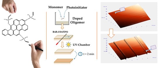
2.1. Preparation of Coatings

Coatings where produced using Laromer UA9048, urethane-acrylate oligomer, and Laromer LR 8887, thinner, from BASF (Schewarsheide GmbH 01986, Schwarzheide, Germany) with a mass ratio of 4:1, respectively. As a photoinitiator, 2-hydroxy-2-metylpropionphenone from Sigma Aldrich (Tres Cantos, Madrid, Spain) was used in a concentration of 5.5 wt.%. This formulation was optimized in a previous work of our research group that aimed to achieve a coating with both high transparency and anti-scratch resistance [26]. The three components were mixed by magnetic stirring avoiding light. A drop of the mixture was placed on a glass and extended using a bar-coating technique (Printcoat instruments Kred model, RK PrintCoat Instruments Ltd., Litlington, UK) producing a 12 µm thick wet film. Finally, samples were cured in an in-house built UVC-chamber for 2 min under laboratory atmosphere. This UVC-chamber consists on a mercury lamp (55 W) and a cylindrical camera covered with aluminum foil.

2.2. Graphene Derivatives Synthesis

GO was provided by Applynano Solutions S.L. (Alicante, Spain) and was produced by modified Hummers and Offemann method [27]. GO is the precursor of the graphene derivatives used as nanofillers in this work: pristine as received GO, reduced GO (rGO), GO functionalized with vinyltriethoxysilane (VTES) (GOvtes) and GO functionalized with VTES and subsequently chemically reduced (rGOvtes).

2.2.1. Graphene Oxide + Chemical Reduction Process (rGO) Synthesis

0.4 g of GO, 200 mL of distilled water, 10 mL of hydrazine (Reagent grade, 55%, Sigma Aldrich, Damstadt, Germany) and of 10 mL of concentrate ammonium hydroxide aqueous solution (25 wt.%) (Briare VWR International S.A.S., Briare, France) were mixed on a three-necked flask. The mixture was stirred for 4 h at 90 °C. Finally, the mixture was cooled down to room temperature and filtered. The wet powder was dried in a conventional oven for 24 h at 60 °C.

2.2.2. Graphene Oxide + VTES (GOvtes) Synthesis

GOvtes was prepared using VTES (GE Specialty Materials Suisse Sarl, Geneva, Switzerland) following the procedure previously described by Wang et al. [28]. Both VTES (2 mL) and GO (0.4 g) were introduced into a three-necked flask and 200 mL of distilled water, and 1 mL of HCl (37%), (Briare VWR International S.A.S., Briare, France) were added to the flask. The mixture was refluxed at 75 °C for 2 h with magnetic stirring to yield the hydrolysis of VTES and the condensation of this molecule over the GO surface. Finally, the mixture was cooled down to room temperature and filtered. The wet powder was dried in a conventional oven for 24 h at 60 °C.

2.2.3. Graphene Oxide + VTES + Chemical Reduction Process (rGOvtes) Synthesis

The process used to synthesize rGOvtes was similar to the process used to obtain GOvtes. In this case, after the 2 h of magnetic agitation, 10 mL of hydrazine (Reagent grade, 55%, Sigma Aldrich) and 10 mL of concentrate ammonium hydroxide aqueous solution (25 wt.%) (Briare VWR International S.A.S.) were added to the flask and heated up to 90 °C for 4 h. Finally, the mixture was cooled down to room temperature and filtered. The wet powder was dried in a conventional oven for 24 h at 60 °C.

2.3. Fabrication of Coatings with Graphene Derivatives as Nanofiller

Introduction of graphene derivatives directly into the resin is a complex process due to the relative high viscosity of the resin, which complicates the proper dispersion of the graphene derivative in the polymer matrix. For this reason, graphene derivatives were introduced into the resin using a solvent-assisted method. Firstly, the necessary amount of graphene derivate to attain the final concentration of nanofiller in the final coating was dispersed in acetone by ultra-sonication (Q500 Sonicator, Qsonica, Newton, CT, USA); secondly, the dispersion was poured in the oligomer and mixed by magnetic stirring; and finally, the acetone was evaporated (and after subsequently trapped in a condenser for reuse) yielding a homogeneous dispersion of the nanofiller in the oligomer. A concentration of 1 wt.% in the final coating was chosen as the optimal one to improve the anti-scratch resistance while still maintaining high transparency. In our research group, we have observed that higher loadings decrease transparency without significantly enhancing the anti-scratch resistance. The coating process continued following Section 2.1.

2.4. Graphene Derivatives and Coatings Characterization

2.4.1. Graphene Derivatives Characterization

Fourier Transform Infrared spectroscopy (FTIR) characterization was made using a BRUKER IFS 66 (Bruker, Billerica, MA, USA) operated in attenuated total reflectance mode. Surface characterization was determined with X-Ray photoelectron spectroscopy (XPS) using a VG-Microtech Multilab 300 (ThermoFisher Scientific, Wattham, MA, USA) with a magnesium/aluminum X-Ray precursor.

2.4.2. Optical Analysis of Coatings

Transmittance analysis was made to determine the transparency of coatings using a UV-Vis/NIR Jasco V-670 (Jasco, Pfungstadt, Germany). The spectra obtained (Ti(λ)) was integrated in order to obtain a parameter ( T i ) that allows the determination of the relative transmittance ( T r i ) of the doped coatings with respect to the transmittance ( T 0 ) of the coating without graphene derivative.
T i   = 200 800 T i ( λ )   d λ
T r i ( % )   = ( T i / T 0 )   ×   100
Furthermore, to observe the dispersion of the GO derivatives in the matrix, Transmission Electron Microscopy (TEM) was used (JEM-2010, JEOL, Akishima, Japan). A thin sample (less than 100 nm thick) was cut using an ultramicrotome and placed on the TEM grid.

2.4.3. Wolf–Wilburn Method

The Wolf–Wilburn method consists on the qualitative determination of the anti-scratch resistance of coatings using pencils with different hardness. This method is described in the American Society for Testing and Materials (ASTM) Designation 3363-05 [29]. The selection of this technique to measure anti-scratch resistance is due to its simplicity and acceptance in the field of surface characterization of industrial coatings. A set of pencils (Dervent Graphics, Workington, UK) was used due to their well-known hardness value in the Wolf–Wilburn scale (Hw). The test consists on the use of pencils with different hardness in a decreasing order to determine the first pencil that does not produce any mark on the coating surface. Then, the hardness of such pencil is taken as the hardness of the coating.

2.4.4. Atomic Force Microscopy (AFM)

AFM does not use radiation to obtain information of the sample examined. In fact, in this type of microscopy, a tip is used to scan the topography of the different samples. The equipment used in this work is a NT-MDT INTEGRA Prima Atomic Force Microscope (INTEGRA Prima, NT-MDT Spectrum Instruments, Moscow, Russia). AFM was used to determine the anti-scratch hardness (Hs) of the coatings. The methodology used is based on the Wolf–Wilburn method and ASTM standard D7027-05 [30]: the tip of AFM is indented in the surface of the coating and pushed back to perform a groove in the surface, performing all test with the same strength. The groove width is measured, and the anti-scratch resistance is calculated from the equation [10,31]:
H s = β ( F a / d 2 )
where Fa is the vertical load in Newton, d is the width of the groove in meters and β is a dimensionless geometrical parameter related to the shape of the tip used.
Prior to the AFM test, the coatings surface was cleaned carefully to remove any dirt and dust. Once the coating was clean, it was placed on the sample area of the AFM using a double-sided adhesive tape. After placing the coating on the AFM, the landing process with the AFM was carried out. Before making any groove, the quality of the surface of the coating was checked for low roughness and low imperfections. To do so, a preliminary scan was performed using a 20 µm/s scan rate. Once an area with enough quality was identified, the grooves were made using a diamond-like carbon coated tip with a Berkovic shape (β = 2.31) (Tap300DLC, BudgedtSensors, Sofia, Bulgaria), a vertical load of 15 µN and a scratch velocity of 0.5 µm/s. In this work, three parallel grooves were made on each surface to check the reproducibility and homogeneity of the anti-scratch values of the samples. Under these conditions, clear grooves were obtained, and the width could be correctly measured. Anti-scratch resistance was calculated from at least 9 width measurements and standard deviation was subsequently determined. The scratching direction was irrelevant since it does not influence the scratching mechanism [32].
In previous work of our research group, a correlation between AFM and Wolf–Wilburn scale was established [26]:
H w = 3.38 H s   +   0.5
This correlation is useful to obtain a value in Wolf–Wilburn scale for samples that exceed the maximum value of the pencil set and serves as a tool to compare results between both scales.

3. Results and Discussion

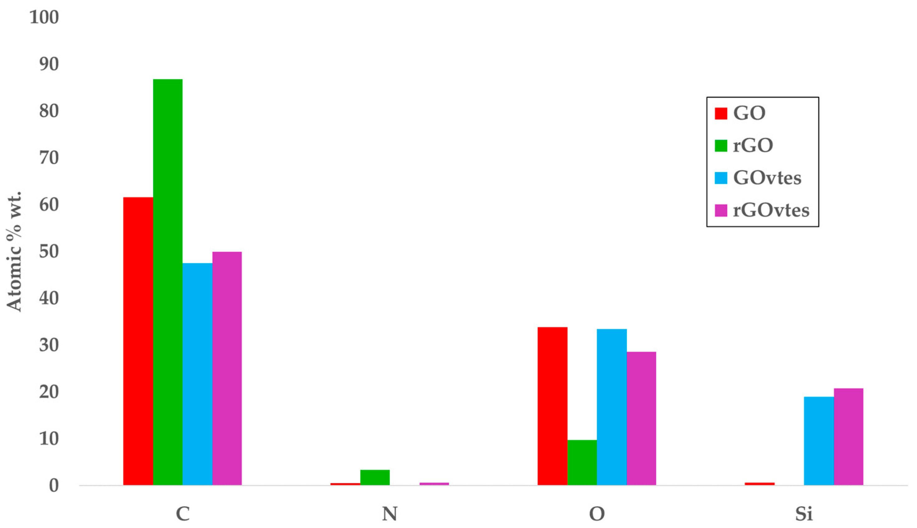
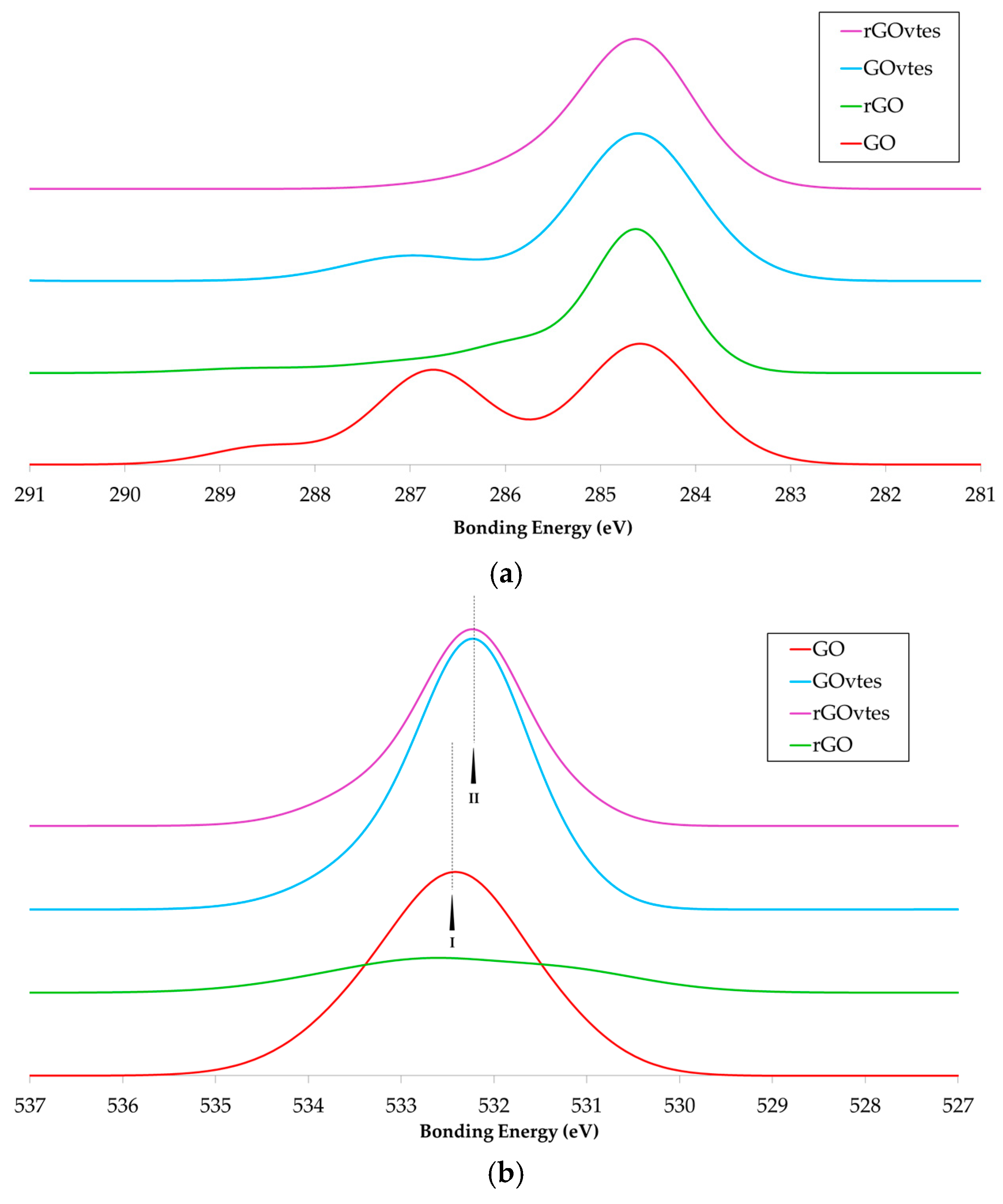
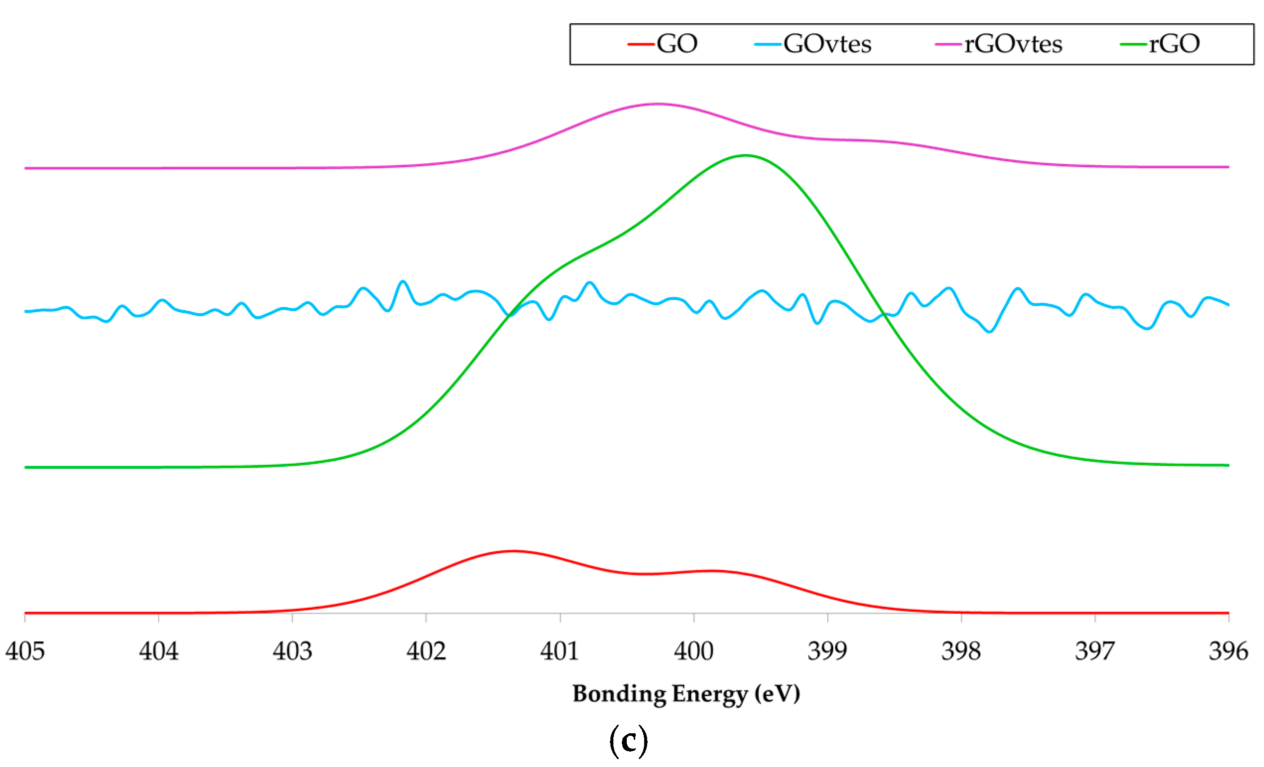
3.1. Graphene Derivatives Characterization

FTIR spectra of the different graphene derivatives are shown in Figure 1. The analysis of the spectrum of GO was done according to previous work [33]. The GO spectrum shows the characteristic hydroxyl groups region between 3000 and 3700 cm−1. Furthermore, hydroxyl signal is also observed between 1100–1200 cm−1, in this case, localized in the basal plane of GO, which might overlap with organosulfate signal. Approximately at 1750 cm−1 the C=O band indicates the presence of carboxylate groups, ketones, lactones, and other groups with a double bond between carbon and oxygen. Water signal normally appears around 1621 cm−1, although in this case, the water peak is overlapped with the C=C peak, usually found at 1600 cm−1. Epoxy group signal appears at 880 cm−1 which means that it is displaced of its characteristic wavenumber at 840 cm−1. Respect the reduced GO sample, its spectrum is almost flat due to the removal of most functional groups contained in the pristine GO, as expected by the reduction process. The process of GO functionalization with VTES (GOvtes) implies a slight reduction of the content of oxygen in the planes, yielding a decrease of the band intensity between 3000 and 3700 cm−1 and of the carboxylate groups band close to 1750 cm−1, the disappearance of the correspondent peak for water in 1621 cm−1 and the consequent increase of the C=C peak at 1600 cm−1. Silane groups appear clearly at lower wavenumbers (500–1500 cm−1): Si–O–C (1100 cm−1) [28], SiO2 (690 cm−1) [34], –Si–H (750 cm−1) [35], –Si–N (960 cm−1) [36], –Si–O–Si– (1250 cm−1) [37], –Si–CH3 (1400 cm−1) [38]. The rGOvtes sample was functionalized and reduced, fact that implies the subsequent elimination of a great part of the oxygenated groups, remaining the silane groups. For instance, the spectrum does not present any peak between 3000 and 3700 cm−1, indicating the disappearance of most of the hydroxyl groups. Between 880–1700 cm−1 residual peaks, such as the peak of water at 1621 cm−1, have also disappeared. Nevertheless, the spectrum shows the same peaks as the GOvtes spectrum for the silane groups.
Using XPS, it is possible to determine the atomic amount of each element found in the surface of the samples (Figure 2) and to which element is bonded (Figure 3). Elemental analysis of the samples, Figure 2, shows that carbon and oxygen are the main elements in the samples. As expected, the reduction process to obtain rGO implies a considerable elimination of oxygen from the surface of the sample and the introduction of a small amount of nitrogen. Furthermore, in Figure 2 is observed the increase of atomic amount of Si for the functionalized samples. It is remarkable that the oxygen amount of GO and GOvtes samples is similar, but not the amount of C. During the functionalization process additional oxygen is introduced in the samples due to the chemical structure of VTES. Furthermore, the reduction process only affects the oxygen groups that have not been involved in the previous functionalization step. For that reason, the rGOvtes sample has a relatively high amount of oxygen, although lower than the GO and GOvtes samples. These results are better explained by observing the principal binding energies detected for the samples (Figure 3). The C 1s spectra of the samples are presented in Figure 3a. The aromatic sp2 C contribution (C=C 284.5 eV) is the main peak, although epoxy-lactone (–C–O–C– 286.5–287.5 eV) and carboxyl groups (–C(O)O 288.9 eV) can also be observed in the GO spectrum. The spectrum of rGO shows a clear reduction in intensity of the binding energies for hydroxyl, epoxy, and carboxyl groups, due to the reduction of surface oxygen after the reduction process. The intensity of these groups is also low for the GOvtes and rGOvtes samples due to the functionalization process, where some of the surface oxygen is bonded to silicon, as previously observed in the elemental analysis. Moreover, the samples that have been chemical reduced (rGOvtes and rGO), show a slight peak at 286.0 eV due to C–N. Figure 3b shows the spectrum for oxygen binding energies (O 1s). A wide peak can be observed for all samples due to the binding energy input of –C=O, C–O and water (531.1, 532.0 and 534.7 eV, respectively) [39]. In this case, a reduction in intensity is only observed for the rGO, as expected, since VTES has high oxygen content. The other spectra (GOvtes and rGOvtes) show an increase in intensity which is associated with the binding energy of Si–O groups (532.0 eV) [40]. The increase observed for rGOvtes is lower than for GOvtes because the chemical reduction removes the oxygen groups not provided by VTES.
Figure 3c shows the N 1s spectra of the samples. It can be observed that the initial GO contains a weak signal indicating the existence of a small number of nitrogenized groups, probably introduced by the Hummers and Offeman reaction, and poorly observed in the elemental analysis. The reduction with hydrazine yields an increase in the nitrogen groups, as can be observed in the case of rGO and rGOvtes. For the case of rGO, the peak for quaternary nitrogen (401.1–401.8 eV) appears with more intensity and displaced to the right respect the GO. Pyrroles (399.7–400.3 eV) and pyridine (398.3–398.7 eV) groups appear due to the reaction with hydrazine [41,42,43]. The same is observed for rGOvtes samples but, in this case, the intensity of these groups is lower, probably because nitrogen has less reaction sites since they have been previously occupied by silicon groups during functionalization. Nitrogen groups are not observed in the GOvtes spectrum, but it is possible that the relatively large amount of oxygenated and silicon groups in the sample make difficult the determination of the nitrogen groups. Herein, XPS analysis has shown the effective modification of the chemical surface of the derivatives.

3.2. Cured Coatings

Visual observation of the cured coatings revealed, in all cases, high quality coatings: coatings were transparent and without any type of surface defects (bubbles, yellowing, cracks…). Transmittance assays were made to estimate transparency of the final coatings. Results are shown in Figure 4, where it is possible to observe that all coatings exhibited high transparency (conventional displays have 40% of transmittance and are considered transparent [44]) but, as expected, coatings containing graphene nanofillers presented lower transmittance than the pristine coating. The coating without nanofiller presented a transmittance above 85%, which is close to the transmittance of the glass substrate used (90%) in the visible region of the spectrum. Table 1 shows the relative transmittance ( T r i ) between the coatings containing 1 wt.% of nanofiller and the coating without nanofiller.
Interestingly, when GO and GOvtes were used, the relative transmittance with respect to the pristine coating was above 90%. The introduction of these nanofillers did not reduce the transmittance considerably, and thus, the coatings produced can be considered highly transparent. These results are similar to the results found in the literature for GO [20,21,22] and imply that the VTES functionalization did not negatively affect the transmittance of the coating. On the other hand, although the coatings containing rGO and rGOvtes presented a lower relative transmittance (approx. 85% and 73%, respectively), they still had a transmittance above that of conventional displays (40%), making these coatings acceptable for their use in optical applications. As an example, Figure 4a shows a cured coating with 1 wt.% of GO.
Figure 5 shows, as an example, TEM images of cured coatings with 1 wt.% of GO and 1 wt.% of rGOvtes. In all cases, a good dispersion of the nanofiller in the matrix was achieved, meaning that there was a good individualization of graphene derivative planes and a homogeneous distribution in the available space.
Regarding the anti-scratch resistance measured with AFM, Figure 6 shows, as an example, the surface of the sample containing 1 wt.% of GO before and after performing the test with the cantilever.
As can be observed in Figure 6, the surface was flat enough to perform the test. Grooves had approximately triangular shape section, as it was expected by the shape of the tip used. From this picture it was possible to determine the width of the grooves using the procedure described in our previous research [26]. Please note that a certain amount of material was deposited next to the groove due to the sample removal by the tip and the direction used to make it.
The AFM anti-scratch resistance results are shown in Figure 7. The introduction of graphene derivatives to the coating matrix improved the anti-scratch resistance in all the cases tested. GO was the graphene derivative that showed lower improvement (~17%) (probably due to a weaker interaction with the matrix compared to the other derivatives tested. The objective of the functionalization process was to decorate the graphene derivatives with functional groups that are related to the polymeric matrix of the coating. For this reason, the introduction of VTES was expected to highly improve the anti-scratch resistance since the vinyl group of VTES would be involved during the polymerization process improving the interface interactions between filler and matrix. Indeed, the coatings with graphene derivatives doped with VTES (GOvtes and rGOvtes) had higher anti-scratch resistance ( ~ 43 % and ~ 45 % , respectively, with respect to the pristine coating) than the coatings with pristine GO. It is of particular importance the results using GOvtes, since it kept the same transparency as GO samples but enhanced its pencil hardness by a factor of ~ 1.22, where rGOvtes attained similar hardness but lower transparency. On the other hand, a high average value of anti-scratch resistance ( ~ 60 % higher with respect to the pristine coating) was achieved using rGO. The chemical reduction of GO to synthesize rGO added nitrogen groups (as shown in XPS results) that in view of the results, could be taking an active role in the curing process, resulting in stronger matrix/filler interactions, which lead to such high improvement of the anti-scratch resistance. Must be noted, however, that given the uncertainty in the AFM measurements, the GOvtes, rGOvtes and rGO-based coatings present, from a statistically point of view, the same anti-scratch hardness performance.
It is well known that the nitrogen in the isocyanate group (principal precursor of urethane bonds) is strongly reactive [45,46] and could be interacting directly with the graphene derivatives depending on the free sites of reaction in the nanofiller used, producing a notable enhancement in the anti-scratch resistance of the coatings. Must be noted that although rGO greatly increased the anti-scratch resistance, it also lead to a high reduction in the relative transmittance with respect to the pristine coating ( T r i   = 85.02%), whereas GOvtes maintained high transparency ( T r i   = 91.50%). From a coating application perspective where high transparency is required the GOvtes-based coatings would have the best performance.
The anti-scratch hardness of the pristine coating was measured using the Wolf–Wilburn scale obtaining a value of 8H. 8H can be considered a good value for anti-scratch resistance for a coating used in a protective coating application: minimum requirements to use a protective coating in touchscreens imply anti-scratch hardness above the human fingernails (2H) [47] and novel protective coatings used in screen application have an anti-scratch resistance close to 8H [48]. In the case of the samples containing graphene derivatives, the pencil with the maximum hardness (9H) could not make any mark on the sample surfaces, which means that theses coatings exceeded the Wolf–Wilburn scale, making these materials suitable for a wider range of coating applications in industry. For example, Choi et. al. [49] used a highly cross-linked siloxane hybrid to fabricate a coating with 9H and used it as a protective hard coating with high anti-scratch resistance for foldable displays, making it comparable to glass surfaces. To obtain a value in terms of Wolf–Wilburn scale for the coatings containing graphene derivatives Equation (4) was used. The results are summarized in Table 2. Notice that the GO coating was not scratched by the 9H pencil, but using the AFM correlation a range between 8–10H is obtained, this is due to the inherent uncertainty of the AFM measurements.
The fact that the pristine coating in this work already showed an anti-scratch hardness of 8H is an indicative of the high quality of the starting materials and formulation, comparing these samples with the results of other authors [8,9,10,11] (see Table 2). This is interesting by itself; nevertheless, the introduction of these adapted graphene derivatives opens a new range of applications in the protective coating industry, not only because the mechanical properties were improved remarkably, but also because they retained high transparency values, making them suitable for optical applications.

4. Conclusions

In this work, transparent UV-curable urethane-acrylate coatings with high anti-scratch resistance (8H) were fabricated. Moreover, the anti-scratch resistance was further enhanced by the addition of different graphene derivatives. Here, the surface chemistry of GO was modified to adapt the pristine material to the final application. All coatings containing rGO, GOvtes, and rGOvtes presented a similar anti-scratch hardness performance with values as high as 12–13H in W.W. scale. In the case of chemically reduced GO using hydrazine, the increase in anti-scratch resistance was mainly attributed to the incorporation of nitrogen groups that had an active role during curing resulting in improved filler/matrix interactions. Although other explanation could involve the increased amount of reaction sites available on which the isocyanate groups of the oligomer could be anchored to. However, the introduction of rGO also diminished the transparency of the coatings by 15%. In the case of GOvtes and rGOvtes the increase in anti-scratch hardness was expected since the vinyl group of VTES is involved during the polymerization process improving the interface interactions between filler and matrix. Coatings in which GOvtes was introduced deserve a special mention since the transparency of the coatings was reduced only by 8% and, in fact, was practically equal to the transparency of coatings containing GO. Furthermore, the coating with GOvtes presents the additional advantage of being environmentally friendlier because some hazardous reagents such as hydrazine are not involved in the fabrication process. Finally, we have shown that the affinity with the polymer matrix can be improved by customizing the surface chemistry of the graphene derivative, yielding a great improvement in the properties of the final coating. We believe that custom-made nanofillers, such as the ones prepared in this work, are key to improve the properties of coatings beyond that of conventional nanocomposites.

Author Contributions

D.D.-L. and R.S.-R. did the experimental work under the supervision of J.C.G.-Q. and I.M.-G., D.D.-L. wrote the main manuscript text and prepared the figures. All authors reviewed the manuscript.

Funding

This research was funded by MINISTERIO DE ECONOMÍA Y COMPETITIVIDAD (MINECO) of Spain (CTQ2014-54772-P and CTQ2013-44213-R); and GENERALITAT VALENCIANA (ROMETEOII/2014/007).

Acknowledgments

The authors wish to thank to BASF for unselfishly providing the resin employed in the present study.

Conflicts of Interest

The authors declare no conflict of interest.

References

  1. Kaewpirom, S.; Kunwong, D. Curing behavior and cured film performance of easy-to-clean UV-curable coatings based on hybrid urethane acrylate oligomers. J. Polym. Res. 2012, 19, 9995. [Google Scholar] [CrossRef]
  2. Llorente, O.; Fernández-Berridi, M.J.; González, A.; Irusta, L. Study of the crosslinking process of waterborne UV curable polyurethane acrylates. Prog. Org. Coat. 2016, 99, 437–442. [Google Scholar] [CrossRef]
  3. Lee, B.-H.; Kim, H.-J. Influence of isocyanate type of acrylated urethane oligomer and of additives on weathering of UV-cured films. Polym. Degrad. Stab. 2006, 91, 1025–1035. [Google Scholar] [CrossRef]
  4. Wang, X.; Xing, W.; Song, L.; Yu, B.; Hu, Y.; Yeoh, G.H. Preparation of UV-curable functionalized graphene/polyurethane acrylate nanocomposite with enhanced thermal and mechanical behaviors. React. Funct. Polym. 2013, 73, 854–858. [Google Scholar] [CrossRef]
  5. Avila-Herrera, C.A.; Gómez-Guzmán, O.; Almaral-Sánchez, J.L.; Yáñez-Limón, J.M.; Muñoz-Saldaña, J.; Ramírez-Bon, R. Mechanical and thermal properties of SiO2–PMMA monoliths. J. Non. Cryst. Solids. 2006, 352, 3561–3566. [Google Scholar] [CrossRef]
  6. Spadaro, G.; Dispenza, C.; Alessi, S.; Tartaglione, G.; Camino, G. Radiation curing of diacrylate glycerolate of bisphenol-A in the presence of an organically modified montmorillonite for the production of flame-resistant polymer—Clay composites. Adv. Polym. Technol. 2006, 25, 109–120. [Google Scholar] [CrossRef]
  7. Dashtizadeh, A.; Abdouss, M.; Mahdavi, H.; Khorassani, M. Acrylic coatings exhibiting improved hardness, solvent resistance and glossiness by using silica nano-composites. Appl. Surf. Sci. 2011, 257, 2118–2125. [Google Scholar] [CrossRef]
  8. Chau, J.L.H.; Hsieh, C.-C.; Lin, Y.-M.; Li, A.-K. Preparation of transparent silica—PMMA nanocomposite hard coatings. Prog. Org. Coat. 2008, 62, 436–439. [Google Scholar] [CrossRef]
  9. Zhang, H.; Tang, L.; Zhang, Z.; Gu, L.; Xu, Y.; Eger, C. Wear-resistant and transparent acrylate-based coating with highly filled nanosilica particles. Tribol. Int. 2010, 43, 83–91. [Google Scholar] [CrossRef]
  10. Suriano, R.; Ciapponi, R.; Griffini, G.; Levi, M.; Turri, S. Fluorinated zirconia-based sol-gel hybrid coatings on polycarbonate with high durability and improved scratch resistance. Surf. Coat. Technol. 2017, 311, 80–89. [Google Scholar] [CrossRef]
  11. Wu, L.Y.L.; Chwa, E.; Chen, Z.; Zeng, X.T. A study towards improving mechanical properties of sol-gel coatings for polycarbonate. Thin Solid Films 2008, 516, 1056–1062. [Google Scholar] [CrossRef]
  12. Lee, C.; Wei, X.; Kysar, J.W.; Hone, J. Measurement of the elastic properties and intrinsic strength of monolayer graphene. Science 2008, 321, 385–388. [Google Scholar] [CrossRef] [PubMed]
  13. Hummers, W.S., Jr.; Offeman, R.E. Preparation of graphitic oxide. J. Am. Chem. Soc. 1958, 80, 1339. [Google Scholar] [CrossRef]
  14. Stankovich, S.; Dikin, D.A.; Dommett, G.H.B.; Kohlhaas, K.M.; Zimney, E.J.; Stach, E.A.; Piner, R.D.; Nguyen, S.T.; Ruoff, R.S. Graphene-based composite materials. Nature 2006, 442, 282–286. [Google Scholar] [CrossRef] [PubMed]
  15. He, H.; Klinowski, J.; Forster, M.; Lerf, A. A new structural model for graphite oxide. Chem. Phys. Lett. 1998, 287, 53–56. [Google Scholar] [CrossRef]
  16. Ramos-Fernandez, G.; Muñoz, M.; García-Quesada, J.C.; Rodriguez-Pastor, I.; Martin-Gullon, I. Role of graphene oxide surface chemistry on the improvement of the interlaminar mechanical properties of resin infusion processed epoxy-carbon fiber composites. Polym. Compos. 2017, 39, E2116–E2124. [Google Scholar] [CrossRef]
  17. Bortz, D.R.; Heras, E.G.; Martin-Gullon, I. Impressive fatigue life and fracture toughness improvements in graphene oxide/epoxy composites. Macromolecules 2012, 45, 238–245. [Google Scholar] [CrossRef]
  18. Lahiri, D.; Hec, F.; Thiesse, M.; Durygin, A.; Zhang, C.; Agarwal, A. Nanotribological behavior of graphene nanoplatelet reinforced ultra high molecular weight polyethylene composites. Tribol. Int. 2014, 70, 165–169. [Google Scholar] [CrossRef]
  19. Kotsilkova, R.; Todorov, P.; Ivanov, E.; Kaplas, T.; Svirko, Y.; Paddubskaya, A.; Kuzhir, P. Mechanical properties investigation of bilayer graphene/poly(methyl methacrylate) thin films at macro, micro and nanoscale. Carbon 2016, 100, 355–366. [Google Scholar] [CrossRef]
  20. Li, L.; Li, W.; Jiu, J.; Suganuma, K. Efficient assembly of high-performance reduced graphene oxide/silver nanowire transparent conductive film based on in situ light-induced reduction technology. Appl. Surf. Sci. 2018, 459, 732–740. [Google Scholar] [CrossRef]
  21. Harun, M.H.; Talib, Z.A.; Ibrahim, N.A.; Chyi, J.L.Y.; Salleh, N.G.N.; Alias, M.S.; Mohamed, M.; Othman, N. Characterization of transparent hydrophobic coating with silica and graphene oxide fillers by sol-gel method. Int. J. Nanoelectron. Mater. 2018, 11, 283–292. [Google Scholar]
  22. Da, S.-X.; Wang, J.; Geng, H.-Z.; Jia, S.-L.; Xu, C.-X.; Li, L.-G.; Shi, P.-P.; Li, G. High adhesion transparent conducting films using graphene oxide hybrid carbon nanotubes. Appl. Surf. Sci. 2017, 392, 1117–1125. [Google Scholar] [CrossRef]
  23. Valentini, L.; Bon, S.B.; Kenny, J.M. Emerging methods for producing graphene oxide composites in coatings with multifunctional properties. J. Mater. Chem. 2012, 22, 21355–21361. [Google Scholar] [CrossRef]
  24. Bittolo Bon, S.; Valentini, L.; Kenny, J.M. Preparation of extended alkylated graphene oxide conducting layers and effect study on the electrical properties of PEDOT: PSS polymer composites. Chem. Phys. Lett. 2010, 494, 264–268. [Google Scholar] [CrossRef]
  25. Akhtar, M.W.; Lee, Y.S.; Yoo, D.J.; Kim, J.S. Alumina-graphene hybrid filled epoxy composite: Quantitative validation and enhanced thermal conductivity. Compos. B Eng. 2017, 131, 184–195. [Google Scholar] [CrossRef]
  26. Domene-López, D.; García-Quesada, J.C.; Martín-Gullón, I. A correlation between the Wolf-Wilburn scale and atomic force microscopy for anti-scratch resistance determination. Prog. Org. Coat. 2018, 125, 325–330. [Google Scholar] [CrossRef]
  27. Lee, S.; Eom, S.H.; Chung, J.S.; Hur, S.H. Large-scale production of high-quality reduced graphene oxide. Chem. Eng. J. 2013, 233, 297–304. [Google Scholar] [CrossRef]
  28. Wang, J.; Xu, C.; Hu, H.; Wan, L.; Chen, R.; Zheng, H.; Liu, F.; Zhang, M.; Shang, X.; Wang, X. Synthesis, mechanical, and barrier properties of LDPE/graphene nanocomposites using vinyl triethoxysilane as a coupling agent. J. Nanoparticle Res. 2011, 13, 869–878. [Google Scholar] [CrossRef]
  29. ASTM D3363-05(2011)e2: Standard Test Method for Film Hardness by Pencil Test; ASTM International: West Conshohocken, PA, USA, 2011; Available online: https://www.astm.org/Standards/D3363.htm (accessed on 23 March 2018).
  30. ASTM D7027-05: Standard Test Method for Evaluation of Scratch Resistance of Polymeric Coatings and Plastics Using an Instrumented Scratch Machine; ASTM International: West Conshohocken, PA, USA, 2005; Available online: https://www.astm.org/DATABASE.CART/HISTORICAL/D7027-05.htm (accessed on 23 March 2018).
  31. Karimzadeh, A.; Ayatollahi, M.R. Investigation of mechanical and tribological properties of bone cement by nano-indentation and nano-scratch experiments. Polym. Test. 2012, 31, 828–833. [Google Scholar] [CrossRef]
  32. Yan, Y.D.; Sun, T.; Liang, Y.C.; Dong, S. Effects of scratching directions on AFM-based abrasive abrasion process. Tribol. Int. 2009, 42, 66–70. [Google Scholar] [CrossRef]
  33. Acik, M.; Lee, G.; Mattevi, C.; Pirkle, A.; Wallace, R.M.; Chhowalla, M.; Cho, K.; Chabal, Y. The role of oxygen during thermal reduction of graphene oxide studied by infrared absorption spectroscopy. J. Phys. Chem. C 2011, 115, 19761–19781. [Google Scholar] [CrossRef]
  34. Vassallo, A.M.; Cole-Clarke, P.A.; Pang, L.S.K.; Palmisano, A.J. Infrared emission spectroscopy of coal minerals and their thermal transformations. Appl. Spectrosc. 1992, 46, 73–78. [Google Scholar] [CrossRef]
  35. Holmes, J.D.; Ziegler, K.J.; Doty, R.C.; Pell, L.E.; Johnston, K.P.; Korgel, B.A. Highly luminescent silicon nanocrystals with discrete optical transitions. J. Am. Chem. Soc. 2001, 123, 3743–3748. [Google Scholar] [CrossRef] [PubMed]
  36. Zhang, L.; Jin, H.; Yang, W.; Xie, Z.; Miao, H.; An, L. Optical properties of single-crystalline α-Si3N4 nanobelts. Appl. Phys. Lett. 2005, 86, 061908. [Google Scholar] [CrossRef]
  37. Nagai, N.; Hashimoto, H. FT-IR-ATR study of depth profile of SiO2 ultra-thin films. Appl. Surf. Sci. 2001, 172, 307–311. [Google Scholar] [CrossRef]
  38. Sachithanadam, M.; Joshi, S.C. Silica Aerogel Composites: Novel Fabrication Methods; Springer: Singapore, 2016. [Google Scholar]
  39. Rodríguez Pastor, I. Tratamientos De Purificación Y Acondicionamiento De Grafenos Para El Desarrollo De Aplicaciones. Ph.D. Thesis, Universidad de Alicante, Alicante, Spain, March 2014. Available online: https://dialnet.unirioja.es/servlet/tesis?codigo=67597 (accessed on 12 March 2018).
  40. Beamson, G.; Bunn, A.; Briggs, D. High-resolution monochromated XPS of poly (methyl methacrylate) thin films on a conducting substrate. Surf. Interface Anal. 1991, 17, 105–115. [Google Scholar] [CrossRef]
  41. Long, D.; Li, W.; Ling, L.; Miyawaki, J.; Mochida, I.; Yoon, S.-H. Preparation of nitrogen-doped graphene sheets by a combined chemical and hydrothermal reduction of graphene oxide. Langmuir 2010, 26, 16096–16102. [Google Scholar] [CrossRef]
  42. Li, M.; Wu, Z.; Ren, W.; Cheng, H.; Tang, N.; Wu, W.; Zhong, W.; Du, Y. The doping of reduced graphene oxide with nitrogen and its effect on the quenching of the material’s photoluminescence. Carbon 2012, 50, 5286–5291. [Google Scholar] [CrossRef]
  43. Hu, T.; Sun, X.; Sun, H.; Xin, G.; Shao, D.; Liu, C.; Lian, J. Rapid synthesis of nitrogen-doped graphene for a lithium ion battery anode with excellent rate performance and super-long cyclic stability. Phys. Chem. Chem. Phys. 2014, 16, 1060–1066. [Google Scholar] [CrossRef]
  44. Shin, S.; Hwang, B.; Zhao, Z.-J.; Jeon, S.H.; Jung, J.; Lee, J.-H.; Ju, B.-K.; Jeong, J.-H. Transparent displays utilizing nanopatterned quantum dot films. Sci. Rep. 2018, 8, 2463. [Google Scholar] [CrossRef]
  45. Grepinet, B.; Pla, F.; Hobbes, P.; Swaels, P.; Monge, T. Modeling and simulation of urethane acrylates synthesis. I. Kinetics of uncatalyzed reaction of toluene diisocyanate with a monoalcohol. J. Appl. Polym. Sci. 2000, 75, 705–712. [Google Scholar] [CrossRef]
  46. Wang, H.; Qin, S.; Yang, X.; Fei, G.; Tian, M.; Shao, Y.; Zhu, K. A waterborne uniform graphene-poly (urethane-acrylate) complex with enhanced anticorrosive properties enabled by ionic interaction. Chem. Eng. J. 2018, 351, 939–951. [Google Scholar] [CrossRef]
  47. Jimbo, Y.; Tamatsukuri, Y.; Ito, M.; Yokoyama, K.; Hirakata, Y.; Yamazaki, S. Reliability and mechanical durability tests of flexible OLED with ALD coating. J. Soc. Inf. Disp. 2015, 23, 313–318. [Google Scholar] [CrossRef]
  48. Lu, S.; Shao, J.; Martin, D.C.; Li, Z.; Schwendeman, I.G. Commercialization of sol-gel based transparent functional coatings. J. Sol-Gel Sci. Technol. 2018, 87, 105–112. [Google Scholar] [CrossRef]
  49. Choi, G.-M.; Jin, J.; Shin, D.; Kim, Y.H.; Ko, J.-H.; Im, H.-G.; Jang, J.; Jang, D.; Bae, B.-S. Flexible hard coating: glass-like wear resistant, yet plastic-like compliant, transparent protective coating for foldable displays. Adv. Mater. 2017, 29, 1700205. [Google Scholar] [CrossRef] [PubMed]
Figure 1. FTIR spectra of the different graphene derivatives used. From bottom to top: Graphene oxide (GO), reduced Graphene oxide (rGO), Graphene oxide functionalized with VTES (GOvtes) and Graphene oxide functionalized with VTES and reduced (rGOvtes).
Coatings 09 00408 g001
Figure 2. Elemental analysis determined through XPS.
Coatings 09 00408 g002
Figure 3. (a) C1s, (b) O1s and (c) N1s spectra of the different graphene derivatives. From the bottom to the top: GO, rGO, GOvtes, and rGOvtes.
Coatings 09 00408 g003aCoatings 09 00408 g003b
Figure 4. (a) Optical picture of a coating containing 1 wt.% of GO showing transparency (allowing the text behind it to be read) and (b) transmittance results for all coatings prepared.
Coatings 09 00408 g004
Figure 5. TEM images of coatings with 1 wt.% of GO (a) and rGOvtes (b).
Coatings 09 00408 g005
Figure 6. AFM images of the surfaces of a 1 wt.% GO-cured coating before (a) and after performing the grooves to determine the anti-scratch resistance of the sample (b).
Coatings 09 00408 g006aCoatings 09 00408 g006b
Figure 7. Anti-scratch resistance of the different cured coatings with graphene derivatives.
Coatings 09 00408 g007
Table 1. Relative transmittance of coatings containing graphene derivatives with respect to the pristine coating.
Coating (0%)GOrGOGOvtesrGOvtes
T i 40,08037,17034,08036,67029,170
T r i (%)100.0092.7285.0291.5072.78
Table 2. Anti-scratch resistance in terms of Wolf–Wilburn scale for different coatings.
ResinSol-gel RelationMolar RatioWolf–Wilburn Hardness (Hw)Ref.
Polycarbonate6B–5B[10,11]
Cross-linked siloxane hybrid9H[49]
Fluorinated zirconia-based sol-gel hybridZirconia/Silica0.092H–3H[10]
0.232H–3H
0.483H–4H
ResinNanofillerConcentrationWolf–Wilburn hardnessRef.
Poly (methyl methacrylate)3H[8]
Modified silica10 wt.%5H
Urethane-Acrylate + TMPTA11H[9]
Nanosilica10 wt.%2H
40 wt.%5H
GLYMO2 + TEOS3H[11]
Colloidal silica10 vol.%2H
20 vol.%3H
30 vol.%4H
40 vol.%4H
Urethane-Acrylate8HThis work
GO1 wt.%8H–10H
rGO11H–13H
GOvtes10H–13H
rGOvtes10H–12H
1. Trimethylolpropane triacrylate; 2. 3-glycidoxypropoyl trimethoxysilane; 3. Tetraethylorthosilicate.

