Article

Corrosion Behavior of AZ91D Magnesium Alloy with a Calcium–Phosphate–Vanadium Composite Conversion Coating

College of Materials Science and Engineering, Qingdao University of Science and Technology, Qingdao 266042, China
*
Author to whom correspondence should be addressed.
Coatings 2019, 9(6), 379; https://doi.org/10.3390/coatings9060379
Submission received: 22 April 2019 / Revised: 28 May 2019 / Accepted: 28 May 2019 / Published: 11 June 2019

Abstract

:
A novel self-healing calcium–phosphate–vanadium (Ca–P–V) composite coating on Mg alloy was successfully fabricated through a chemical conversion method. The effects of the vanadium concentration on the anticorrosion property of the substrate were also tested. The Ca–P–V coating with the main composition of CaHPO4, Ca3(PO4)2, and Mg3(PO4)2, with some hydroxides of V(V) dispersed into it has a similar morphology to the single vanadium coating. The corrosion behaviour of the Ca–P–V coating was studied through the electrochemical tests and the scratch immersion test in 3.5 wt % NaCl solution. The results showed that the Ca–P–V coated samples not only exhibit good corrosion resistance property, but also show self-healing ability. The ions of Ca, P, and V released from the coating can migrate in the corrosion solution and form a new compound layer on the damaged zone.

1. Introduction

To enhance the anticorrosion property of Mg alloys, many types of protective measures have been applied, and one of the useful methods is to fabricate a chemical conversion coating on their surfaces [1,2,3,4,5]. Compared with other methods including anodizing [6,7], electroplating [8,9], plasma electrolytic oxidation [10,11], radio frequency (RF) magnetron sputtering [12,13], and laser surface melting [14], the chemical conversion method is interesting owing to its low cost, easy control, and efficiency [15]. Chromate conversion coating (CCC) is a traditional and representative coating on Mg alloys, but Cr(VI) has high toxicity and can cause environmental pollution and damage [16,17]. Therefore, it is necessary to develop eco-friendly protective coating systems with high corrosion resistance on magnesium alloys to replace CCCs.
Phosphate conversion coating on Mg alloys has been studied for many years, which is considered to be an alternative to CCC [18]. Some divalent cations such as Ca2+, Zn2+ and Mn2+ are usually added to the phosphating bath to further enhance the anticorrosion property of the phosphate conversion coating. In our previous study, we developed an environment-friendly calcium phosphate conversion coating on AZ91D alloy, and demonstrated an enhanced anticorrosion ability of the conversion coating [19]. Zeng et al. prepared Zn phosphate coating and Zn–Ca composite coating on AZ31 alloy [20]. The results showed that the Zn–Ca coating was denser and exhibited better anticorrosion ability than the single Zn coating [20]. Chen et al. deposited a double-layered coating including Mg(OH)2 and (Mg/Mn)3(PO4)2 on AZ91D alloy, which shows better corrosion resistance than CCC based on the result of the salt spray test [21]. Phosphate conversion coating has good corrosion resistance as proved by the researchers, but it does not show a “self-healing” ability.
Vanadate conversion coating has gained much attention owing to a self-healing property similar to CCC. Hamdy et al. reported that a high concentration of vanadate solution (50 g/L) can protect the substrate with a proven self-healing property [22]. They exhibited similar effects on the ZE41 alloy [23]. Li et al. have obtained the optimum operating conditions for a V coating on the substrate at 60 °C, 0.6 M NaVO3 solution [24]. They proved the self-healing capabilities of vanadate conversion coating by electrochemical tests. To further enhance the anticorrosion ability of the vanadate based coating and reduce the concentration of vanadate, some researchers have designed self-healing composite coatings based on vanadium modified by other conversions. Jiang et al. prepared a Ce–V composite layer on AZ31, which exhibits two layers with an amorphous structure and a significantly improved corrosion resistance than CCC on AZ31 alloy [25]. Liu et al. prepared a V–Zr composite conversion coating on Al alloy with a self-repairing ability [26].
Combining self-healing ability with improved corrosion resistance is a promising substitute coating for CCC on magnesium alloys. In this study, we report for the first time a novel calcium–phosphate–vanadium composite coating on AZ91D magnesium alloy by a facile chemical conversion method. Compared with the pure Ca–P coating, the Ca–P–V composite coatings not only have high corrosion resistance but also have self-healing ability due to the addition of vanadium. The effect of metavanadate concentration on the anticorrosion property of the composite coating was studied. Scanning electron microscopy with energy dispersive spectroscopy (SEM-EDS) and X-ray photoelectron spectroscopy (XPS) were applied to study the morphology and composition of the composite coating. In particular, both electrochemical and scratch tests were used to prove the self-healing behaviour of the prepared composite coating.

2. Materials and Methods

2.1. Materials and Surface Preparation

As-cast AZ91D magnesium alloy (Hongqi Metal Materials, Yantai, China) with a chemical composition of 90.31 wt % Mg, 8.77 wt % Al, 0.74 wt % Zn and 0.18 wt % Mn as used as the substrate material. The alloy samples with a size of 12 mm × 12 mm × 12 mm were mechanically ground with SiC sandpaper up to 2000 grit, ultrasonically cleaned in acetone for 5 min, rinsed with distilled water and then dried in air.

2.2. Preparation of the Conversion Coating

The pre-treated AZ91D substrates were directly immersed in a solution of ammonium dihydrogen phosphate (NH4H2PO4, 0.2 M), calcium nitrate (Ca(NO3)2, 0.1 M), sodium metavanadate (NaVO3, 0.04, 0.08 and 0.12 M) with a pH of 3 at 40 °C for 20 min. Finally, the samples were removed from the solution, rinsed with distilled water, and dried in hot air.

2.3. Surface Characterization

The surface and cross-section morphologies of the as-prepared composite coating were observed by a field emission-scanning electron microscopy (FE-SEM, JSM-6700F, JEOL, Akishima, Japan) equipped with EDS (JSM-6700F, JEOL, Akishima, Japan). For cross-section observation, the coated sample was firstly embedded in resin under certain pressure and temperature, and then mechanically ground with SiC sandpaper up to 2000 grit. The chemical state of elements in the coating was analyzed by XPS using a XSAM800 (Kratos, Manchester, UK) instrument with Al Kα radiation (1486.6 eV).

2.4. Electrochemical Measurements

Electrochemical measurements were used to evaluate the corrosion resistance of the uncoated and Ca–P–V coated AZ91D samples in 3.5 wt % NaCl solution at room temperature. The samples with an exposed surface area of 1.44 cm2 were moulded in epoxy resin for all the electrochemical tests. A classic three-electrode system consisting of a sample as a working electrode, a saturated calomel electrode (SCE) as the reference electrode, and a platinum foil as the counter electrode was used in this experiment. Polarization measurements were performed for samples previously immersed for 30 min at the open circuit potential (OCP) in 3.5 wt % NaCl solution. The scan rate was 0.80 mV/s with a scan range of ±250 mV with reference to the OCP. Electrochemical impedance spectroscopy (EIS, CS380 in COM3, Wuhan Corrtest Instruments Corp., Ltd., Wuhan, China) measurements were carried out at OCP in the frequency range between 100 kHz–10 mHz using a 10 mV amplitude perturbation. EIS data were analyzed by ZView software (version 3.0) to fit the experimental data and synthesize the equivalent circuit. All electrochemical tests were normally duplicated three times to confirm good reproducibility.

2.5. Scratch Immersion Test

The scratch immersion test was employed to testify the self-healing property of the Ca–P–V coated samples. A scratch was cut on the surface of the coated samples by using a scalpel, and they were immersed in 3.5 wt % NaCl solution for 1, 2 and 3 d. As a comparison, the same scratch immersion test was also conducted on the uncoated AZ91D substrate. The surface morphologies and elements composition of the scratch before and after immersion were observed by SEM-EDS analysis.

3. Results and Discussion

3.1. Effect of NaVO3 Concentration on the Corrosion Resistance of the Ca–P–V Composite Coating

To obtain the optimum concentration of NaVO3, EIS measurements of the specimens were used in this study. Figure 1 presents the Nyquist plots for specimens coated with or without the Ca–P–V composite coatings in 3.5 wt % NaCl solution. Compared with the uncoated sample, all the coated samples show better anticorrosion property. By increasing the concentration of NaVO3, the capacitive loop diameter at high frequency also increases, which is related to high corrosion resistance. Moreover, the sample coated with 0.08 M NaVO3 shows the largest loop compared with other coated samples. According to the EIS results, the 0.08 M NaVO3 was selected as the optimum concentration to prepare the coated samples with Ca–P–V composite coatings.

3.2. Morphology and Composition of the Ca–P–V Composite Coating

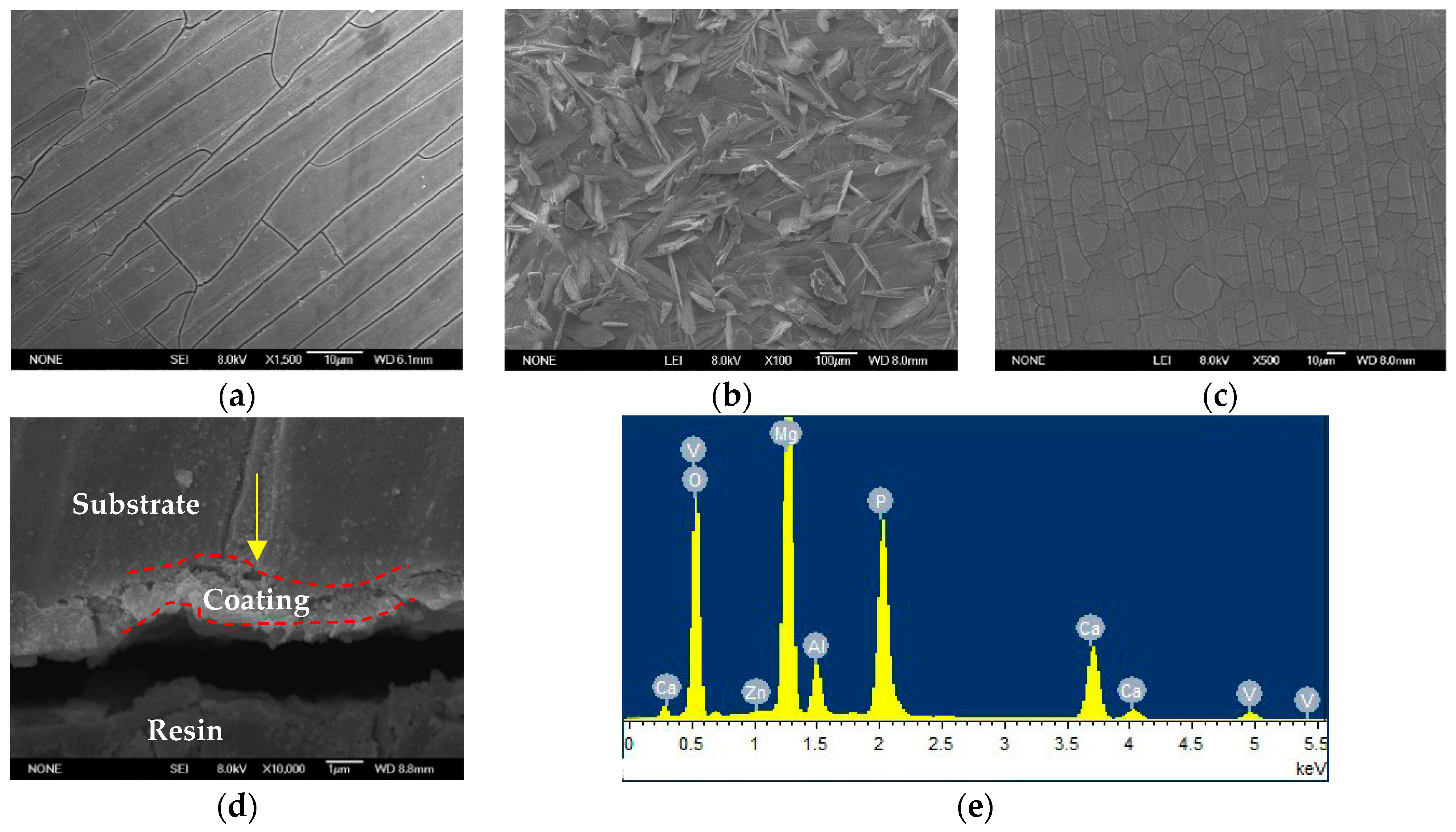
SEM images of surface morphologies of the single vanadium coating, Ca–P as well as Ca–P–V composite coatings are presented in Figure 2. The Ca–P coating consists of a large number of plate-shaped particles (Figure 2b). While the Ca–P–V composite coating exhibits a grid-like structure with a large number of micro-cracks (Figure 2c), which is similar to the single vanadium coating (Figure 2a). Figure 2d indicates that the composite coating has a thickness of about ~1 μm. The element composition of the composite coating was analyzed through EDS as shown in Figure 2e and shows that the coating consists of Mg, Al, Zn, O, Ca, P and V elements. Table 1 shows the contents of these elements obtained from EDS analysis. The EDS results of the pure vanadium as well as the Ca–P coating were also provided in Figure S1. The elements of Mg, Al, and Zn mainly come from the coating as well as the AZ91D substrate. The coexistence of Ca, P, and V suggests that the three elements of Ca, P, and V take part in the coating formation.
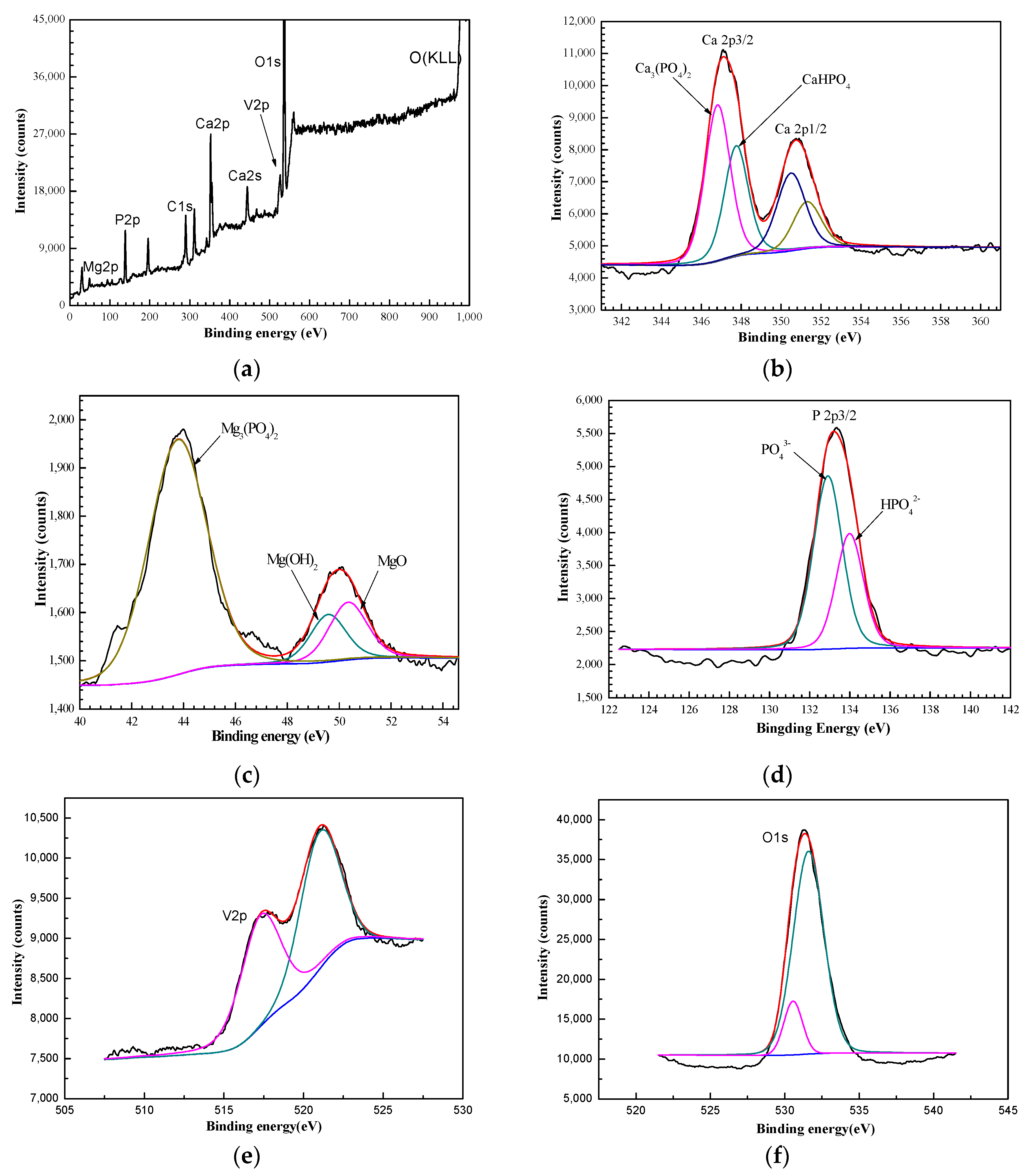
The XPS results of the composite Ca–P–V coating are shown in Figure 3. The XPS survey scanning spectrum indicates the coexistence of Mg, Ca, O, P and V elements (Figure 3a), which is in agreement with the EDS result. Fitting the high-resolution XPS peaks for Ca 2p, Mg 2p, P 2p and V 2p are presented in Figure 3b–f, respectively. The peak of Ca 2p is composed of Ca 2p3/2 and Ca 2p1/2 peaks. The binding energies of Ca 2p3/2 peaks at 347.75 and 346.85 eV can be attributed to CaHPO4·2H2O and Ca3(PO4)2, respectively [27,28]. The Mg 2p in Figure 3c displays three peaks, corresponding to Mg3(PO4)2, MgO and Mg(OH)2, respectively [21,27,28]. As shown in Figure 3d, the P 2p spectrum displays two peaks, corresponding to PO43− and HPO42− [28], which is in agreement with the result of Ca 2p. In Figure 3e, the binding energy of V 2p3/2 is 517.5 eV indicating V(V), but the O 1s X-ray satellite peak has a serious impact on it [29,30,31]. Figure 3f shows the XPS spectrum of O 1s, which consists of two peaks. The binding energies at 530.56 and 531.60 eV can be attributed to V–O and V–OH, respectively [24,25]. Moreover, the peak at 531.60 eV has much more intensity, proving that V–OH (hydroxides) might be the main compound. In summary, the Ca–P–V composite coating mainly consists of CaHPO4·2H2O, Ca3(PO4)2, Mg3(PO4)2 and hydroxides of V(V).

3.3. Formation Mechanism of the Ca–P–V Composite Coating

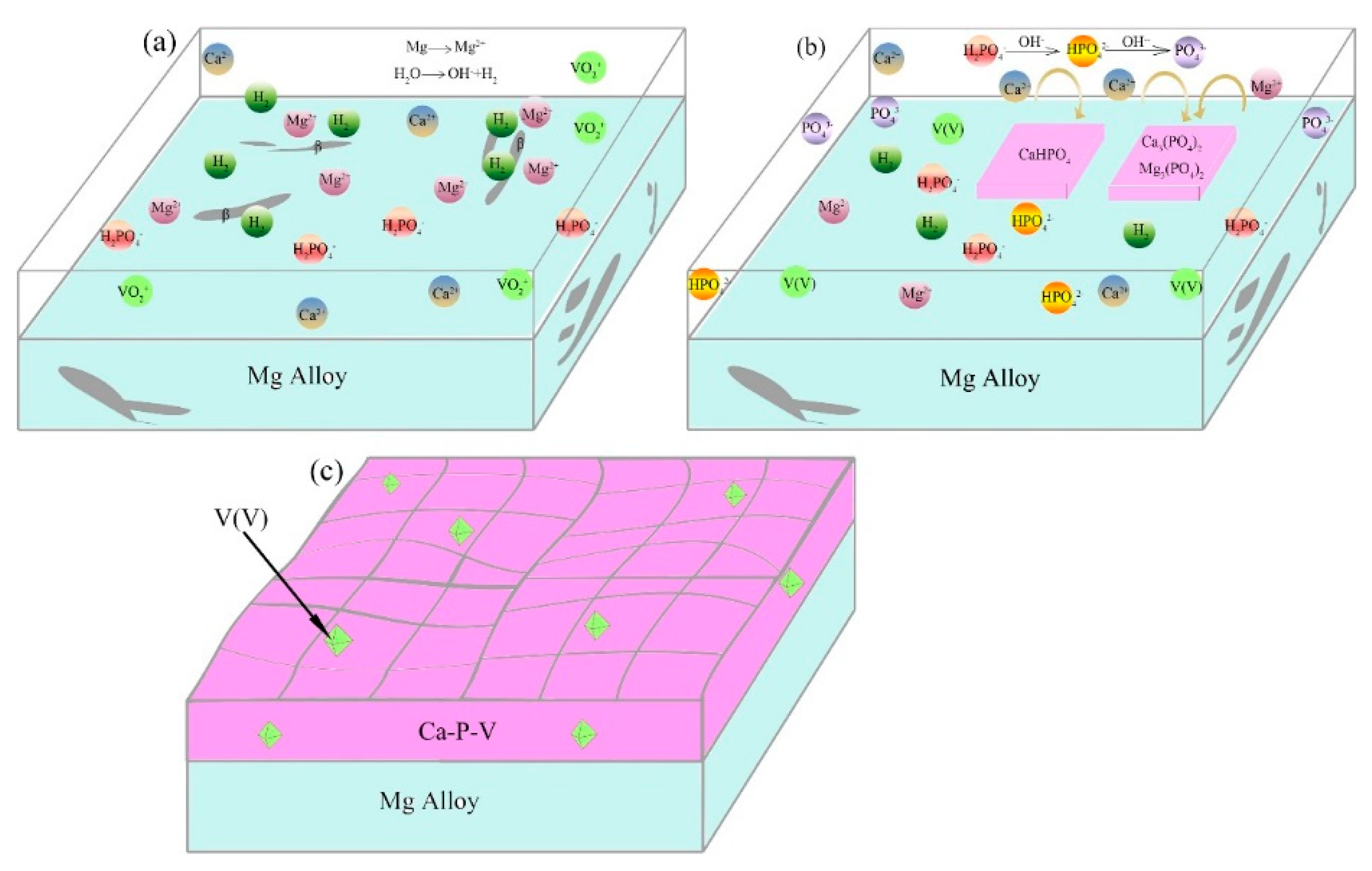
According to the above results, a formation mechanism of the composite Ca–P–V coating is schematically depicted in Figure 4. It is known that the valence state of V in the solution depends on the solution pH value and the concentration of V. In this study, the concentration of V is 0.08 M and the pH of the conversion solution is 3, the colour of the conversion solution is red (Figure S2), indicating that vanadium exists in a form of VO2+ [25,32]. Low corrosion potential of α-Mg promoted the formation of Mg2+ (Equation (1)); hydrogen was given off from the β-Al17Mg12 (Equation (2)), which has a higher potential (Figure 4a).
Mg → Mg2+ + 2e
2H+ + 2e → H2
The above reactions raise the pH of the solution adjacent to the metal surface (from 3 to 7–8) [1,2,33,34], which makes H2PO4 being transferred into HPO42− and PO43− according to the following reactions [33]:
H2PO4 + OH → HPO42− + H2O
HPO42− + OH → PO43− + H2O
As a result, the generated HPO42− and PO43− may react with the Ca2+ and Mg2+ in the solution to form insoluble CaHPO4·2H2O, Ca3(PO4)2 and Mg3(PO4)2 precipitates on the substrate surface according to the following reactions [35,36]:
Ca2+ + HPO42− + 2H2O → CaHPO4·2H2O
3Ca2+ + 2PO43− → Ca3(PO4)2
3Mg2+ + 2PO43− → Mg3(PO4)2
MgHPO4 is not involved in the conversion coating, because it is slightly soluble in aqueous solution [27]. The values of the thermodynamic function H0 for Mg3(PO4)2 and Mg(OH)2 are −3780.66 and −924.16 kJ/mol, respectively [16,27,35]. Thus, Mg2+ preferentially reacts with PO43− to form Mg3(PO4)2 rather than Mg(OH)2. The composition of the products of the reactions (5)–(7) can be proved by the XPS results. Meanwhile, the increase of the solution pH also triggers the formation of VO(OH)3 through hydrolysis of VO2+ [26,32,37]:
VO2+ + 2H2O → VO(OH)3 + H+
Figure S2 shows that after chemical conversion treatment the colour of the solution is still red, indicating the form of V(V). Therefore, the final structure of the Ca–P–V coating is a grid-like film composed of CaHPO4·2H2O, Ca3(PO4)2 and Mg3(PO4)2 with some hydroxides of V(V) dispersed into the film (Figure 4c).

3.4. Anticorrosion Property of the Ca–P–V Coated Samples

To study the anticorrosion property of the samples, both the potentiodynamic polarization measurements and EIS analysis were carried out on different specimens in 3.5 wt % NaCl solution. Furthermore, to study the self-healing behaviour of the specimens, the Ca–P–V composite coatings were soaked in 3.5 wt % NaCl solution for different times before electrochemical tests. The Ca–P–V coated sample (0 d) indicates the sample is not soaked in solution before tests.
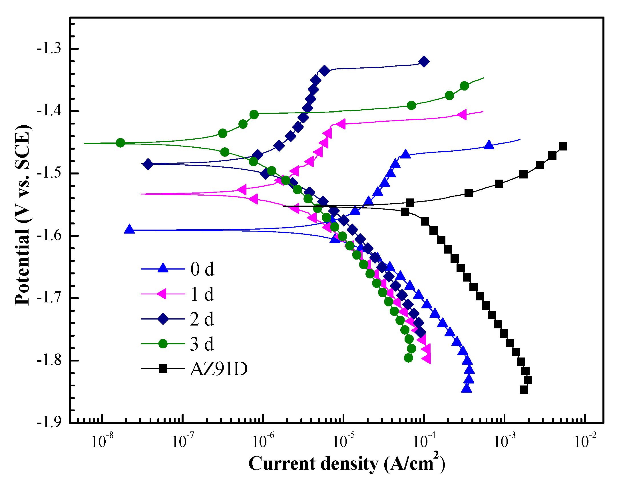
Figure 5 shows the polarization curves of the uncoated and Ca–P–V coated samples after being immersed for different times (0, 1, 2, and 3 d). The corrosion parameters of the samples derived from Figure 5 are shown in Table 2, where Ecorr and Icorr are corrosion potential and corrosion current density, respectively. Comparing with the uncoated AZ91D substrate, the Ca–P–V coated sample (0 d) has a lower Ecorr. But the Ecorr values of the composite coating increased gradually with increasing immersion time, suggesting that the initial pitting corrosion can be suppressed by further immersion in solution. Compared to the uncoated AZ91D, the Icorr of the coated samples is dropped by two orders of magnitude, which indicates the anticorrosion ability is greatly improved due to the conversion coating. Notably, the Icorr of the coated samples decreases from 1.39 × 10⁻⁶ to 3.84 × 10⁻⁷ A/cm2 with the extended immersion time from 1–3 d, which demonstrates a remarkably restrained corrosion process. It is obvious that the Ca–P–V coated sample after being immersed for 3 d exhibits the best corrosion resistance and a self-healing behaviour.
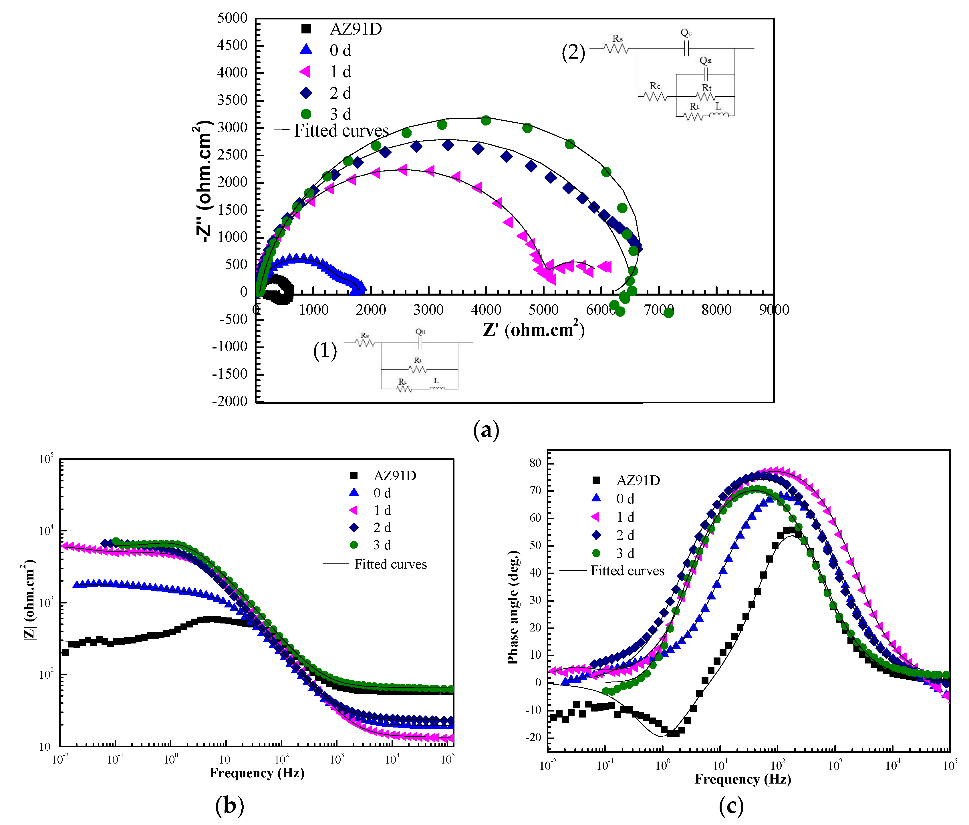
Figure S3 shows the OCP data of the uncoated AZ91D as well as the Ca–P–V coated samples (0 d) in 3.5 wt % NaCl solution. For the uncoated AZ91D substrate, the OCP decreases to a steady value of −1.585 V (vs. SCE) with less fluctuation in about 15 min. The initial OCP of the coated sample (0 d) is relatively negative, which may due to some defects such as micro-cracks (as shown in Figure 2c) in the coating that results in the substrate to be exposed to electrolyte. However, the OCP of the coated sample (0 d) after 10 min increases gradually with time and finally reaches a relative constant value of about −1.684 V (vs. SCE) after 40 min of soaking. The Nyquist plots for uncoated AZ91D substrate and Ca–P–V coated samples after being soaked in 3.5 wt % NaCl solution for 0, 1, 2 and 3 d at OCP are shown in Figure S4 and Figure 6, respectively. The plot of the uncoated AZ91D substrate consists of two loops. The inductive loop in the low frequency may result from the relaxation of the absorbed species, indicating the occurrence of pitting corrosion [38,39]. Moreover, the diameter of the capacitive loop has a trend of first increases and decreases with the extension of soaking time (Figure S4). This is because the protective effect of corrosion products on the substrate is weak and will gradually lose its protective effect with the increase of immersion time. The Ca–P–V composite coating after immersion for different days show capacitive loops at high frequencies with weak inductive loops at the low frequencies. The corresponding equivalent circuit models used to fit the EIS data of the uncoated AZ91D and the Ca–P–V coated sample (3 d) were inserted in Figure 6. The capacitive loops at high frequencies of the coated samples can be referred to the good barrier properties of the Ca–P–V composite coating [40], and the weakening of the inductive loops also indicates the better performance of the coating with improved pitting corrosion resistance. Moreover, the capacitive loop diameter increases gradually with the increase of immersion time, which suggests an improved corrosion resistance. These confirm that the anticorrosion ability of the composite coating does not reduce but is increased with the extension of immersion time.

3.5. Self-Healing Behaviour of the Scratched Ca–P–V Coated Specimens

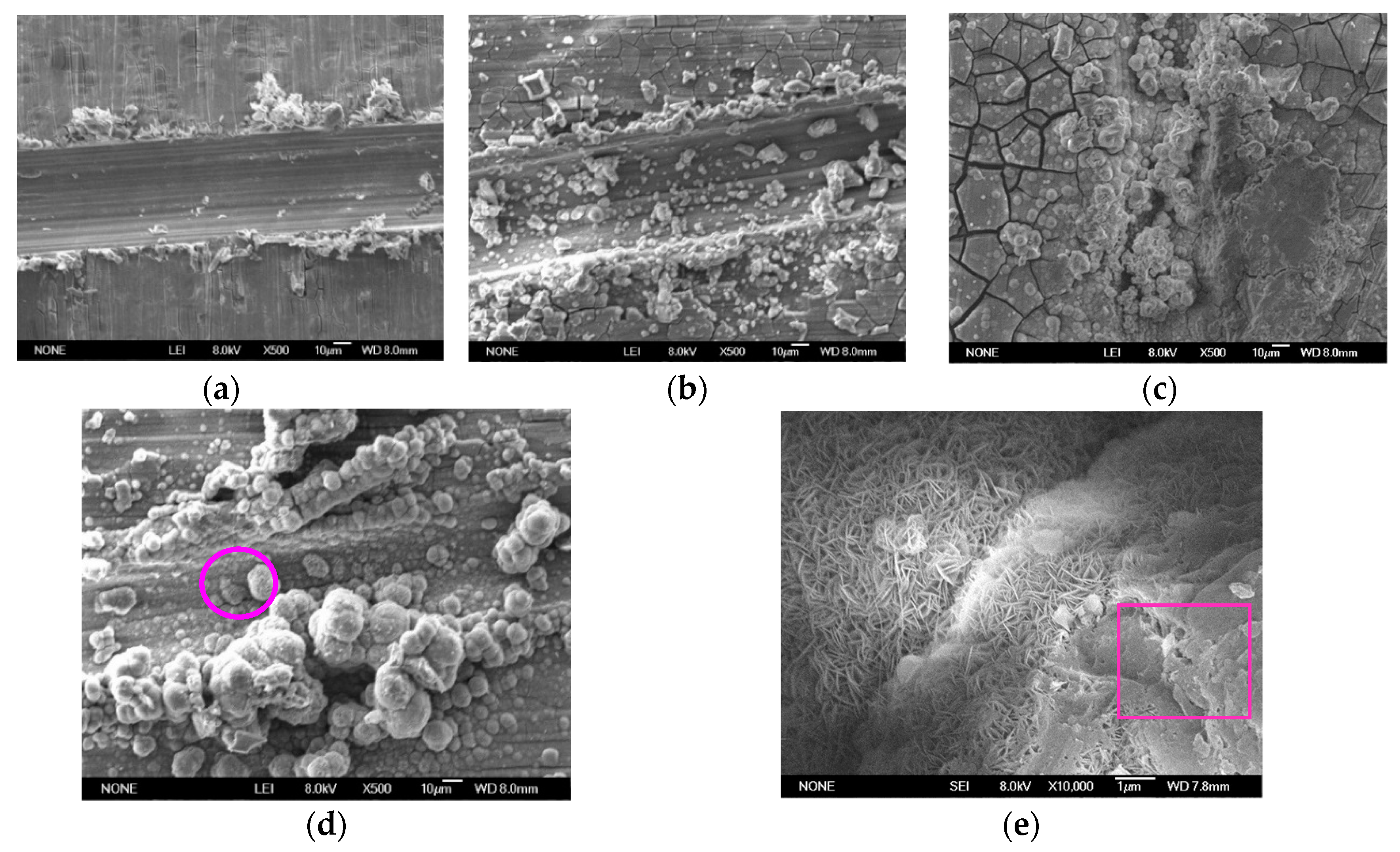
SEM morphologies of the scratched Ca–P–V coated samples after being immersed in 3.5 wt % NaCl solution are shown in Figure 7. Figure 7a shows that the new scratch is smooth and the edge of the scratch is sharp. After 1 d immersion, some newly formed precipitates appear on the bottom of the scratch (Figure 7b). With the prolongation of soaking time, the precipitates increase and gradually fill the scratch, and the edge of the scratch becomes indistinct. After being immersed for 3 d (Figure 7d), the scratch becomes relatively flat and is fully and closely covered by spherical particles. Furthermore, Figure 7e shows that the spherical particles have a flower-like morphology with many nanoplates interspersed with each other. Except for the flower-like precipitates, there are some other precipitates covered on them as indicated by the square in Figure 7e. The flower-like morphology of the newly formed spherical particles is similar to that reported about the self-healing behaviour of single V coating by other researchers [22,23,24]. Consequently, the scratch was covered by more and more spherical particles and was sealed in this way to prevent further contact with the corrosion solution (Figure S5). These results are consistent with the EIS result, proving the self-healing property of the coating.
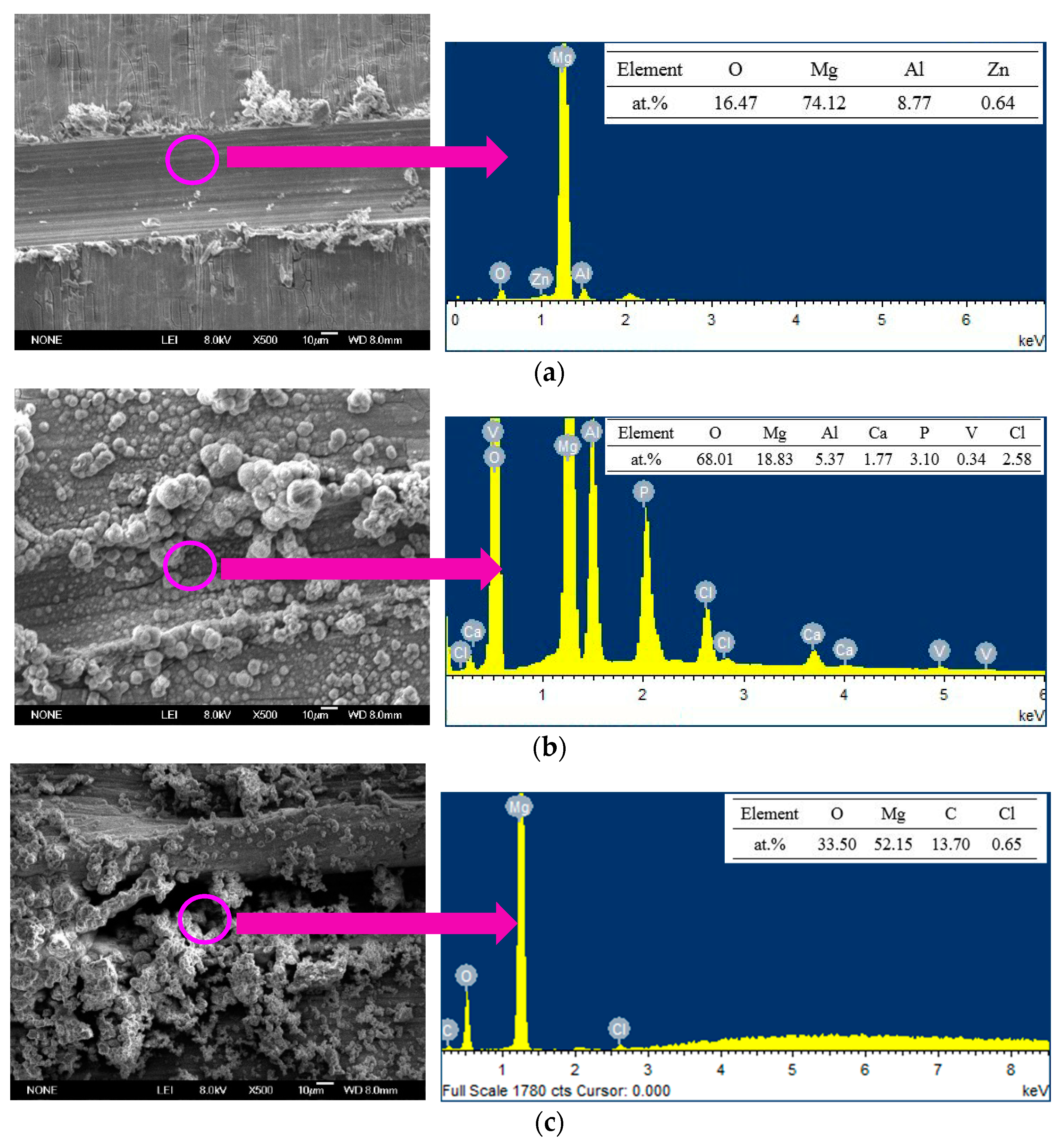
To study the self-healing mechanism of the Ca–P–V composite coating, the EDS analysis at the scratch of the Ca–P–V coated sample before and after immersion was conducted as shown in Figure 8a,b. As a comparison, the SEM-EDS analysis of the uncoated AZ91D with a scratch after immersion in 3.5 wt % NaCl solution for 2 d was also conducted (Figure 8c). The scratch of the Ca–P–V coated sample before immersion mainly consists of Mg, Al and Zn (Figure 8a), which is the same composition as the AZ91D substrate. After being corroded for 2 d, the newly formed compound contains Ca, P, O and V elements, except for the Mg and Al elements mainly from the substrate (Figure 8b), implying the formation of calcium phosphate and/or hydrogen phosphate, magnesium phosphate and vanadium oxides and/or hydroxides. Figure 8c shows that some loose corrosion products are gathered around the scratch of the uncoated sample and the corresponding EDS analysis indicates that the corrosion products are composed of Mg and O, which is different from the products formed on the scratched Ca–P–V coated sample as shown in Figure 8b. Therefore, it can be concluded that the products appeared on the scratched Ca–P–V coating after immersion are newly formed compounds rather than corrosion products, suggesting that Ca, P as well as V elements can migrate from the surrounding layer to the scratched zone and form some new compounds. The self-healing ability of the Ca–P–V composite coating is beneficial for AZ91D alloy because it can prevent further corrosion through repairing scratches or cracks.

4. Conclusions

In this study, a new self-healing Ca–P–V conversion coating on AZ91D alloy was designed as a chromate replacement. The Ca–P–V composite coating exhibits a grid-like structure and mainly consists of CaHPO4, Ca3(PO4)2 and Mg3(PO4)2 with some hydroxides of V(V) dispersed into the coating. The electrochemical tests demonstrate that the anticorrosion property of the Ca–P–V coated substrate is enhanced obviously. Moreover, the Ca–P–V composite coating exhibits good self-healing ability according to the scratch immersion and electrochemical tests. Both Ca, P, and V play important roles in the self-healing process of the coating in this study. The composite Ca–P–V coating with enhanced anticorrosion performance and self-healing property may have great potential for use as a replacement for chromate conversion coating.

Supplementary Materials

The following are available online at https://www.mdpi.com/2079-6412/9/6/379/s1, Figure S1: SEM images and EDS analysis of (a) pure V coating and (b) Ca–P coating, Figure S2: photos of the different solutions: (a) the NaVO3 solution; (b) the conversion solution after adjusting pH to 3.0; (c) the conversion solution after removing the AZ91D samples, Figure S3: open circuit potential curves of the uncoated AZ91D substrate and the substrate coated with Ca–P–V composite coating in 3.5 wt % NaCl solution as a function of time. The Ca–P–V coated sample (0 d) indicates the sample is not immersed in 3.5 wt % NaCl solution before OCP test, Figure S4: Nyquist plots for uncoated AZ91D substrate after immersion for different days in 3.5 wt % NaCl solution, Figure S5: SEM images of the Ca–P–V coating after immersion in 3.5 wt % NaCl solution for (a) 3 d and (b) 5 d.

Author Contributions

Conceptualization, R.S.; Investigation, T.L. and S.Y.; Writing—Original Draft Preparation, T.L.; Writing—Review and Editing, R.S. and S.Y.

Funding

This research was funded by the National Natural Science Foundation of China (Project No. 51602169).

Acknowledgments

We thank LetPub (www.letpub.com) for its linguistic assistance during the preparation of this manuscript.

Conflicts of Interest

The authors declare no conflict of interest.

References

  1. Jayaraj, J.; Raj, S.A.; Srinivasan, A.; Ananthakumar, S.; Pillai, U.T.S.; Dhaipule, N.G.K.; Mudali, U.K. Composite magnesium phosphate coatings for improved corrosion resistance of magnesium AZ31 alloy. Corros. Sci. 2016, 113, 104–115. [Google Scholar] [CrossRef]
  2. Chen, X.B.; Birbilis, N.; Abbott, T.B. A simple route towards a hydroxyapatite-Mg(OH)2 conversion coating for magnesium. Corros. Sci. 2011, 53, 2263–2268. [Google Scholar] [CrossRef]
  3. Zhang, Y.; Tang, S.; Hu, J.; Lin, T. Formation mechanism and corrosion resistance of the hydrophobic coating on anodized magnesium. Corros. Sci. 2016, 111, 334–343. [Google Scholar] [CrossRef]
  4. Gray, J.; Luan, B. Protective coatings on magnesium and its alloys—A critical review. J. Alloy Compd. 2002, 336, 88–113. [Google Scholar] [CrossRef]
  5. Wang, J.L.; Ke, C.; Pohl, K.; Birbilis, N.; Chen, X.B. The unexpected role of benzotriazole in mitigating magnesium alloy corrosion: A nucleating agent for crystalline nanostructured magnesium hydroxide film. J. Electrochem. Soc. 2015, 162, C403–C411. [Google Scholar] [CrossRef]
  6. Blawert, C.; Dietzel, W.; Ghali, E.; Song, G. Anodizing treatments for magnesium alloys and their effect on corrosion resistance in various environments. Adv. Eng. Mater. 2006, 8, 511–533. [Google Scholar] [CrossRef]
  7. Khan, S.A.; Miyashita, Y.; Mutoh, Y. Corrosion fatigue behavior of AM60 magnesium alloy with anodizing layer and chemical-conversion-coating layer. Mater. Corros. 2015, 66, 940–948. [Google Scholar] [CrossRef]
  8. Wang, S.H.; Guo, X.W.; Sun, C.; Gong, J.; Peng, L.M.; Ding, W.J. Electrodeposition of Cu coating with high corrosion resistance on Mg–3.0Nd–0.2Zn–0.4Zr magnesium alloy. Trans. Nonferrous Met. Soc. China 2014, 24, 3810–3817. [Google Scholar] [CrossRef]
  9. Liu, Y.; Yin, X.; Zhang, J.; Yu, S.; Han, Z.; Ren, L. A electro-deposition process for fabrication of biomimetic super-hydrophobic surface and its corrosion resistance on magnesium alloy. Electrochim. Acta 2014, 125, 395–403. [Google Scholar] [CrossRef]
  10. Lu, X.; Blawert, C.; Kainer, K.U.; Zheludkevich, M.L. Investigation of the formation mechanisms of plasma electrolytic oxidation coatings on Mg alloy AM50 using particles. Electrochim. Acta 2016, 196, 680–691. [Google Scholar] [CrossRef]
  11. Klein, M.; Lu, X.; Blawert, C.; Kainer, K.U.; Zheludkevich, M.L.; Walther, F. Influence of plasma electrolytic oxidation coatings on fatigue performance of AZ31 Mg alloy. Mater. Corros. 2017, 68, 50–57. [Google Scholar] [CrossRef]
  12. Surmeneva, M.A.; Ivanova, A.A.; Tian, Q.M.; Pittman, R.; Jiang, W.S.; Lin, J.J.; Liu, H.H.; Surmenev, R.A. Bone marrow derived mesenchymal stem cell response to the RF magnetron suppter deposited hydroxyapatite coating on AZ91 magnesium alloy. Mater. Chem. Phys. 2019, 221, 89–98. [Google Scholar] [CrossRef]
  13. Mukhametkaliyev, T.M.; Surmeneva, M.A.; Vladescu, A.; Cotrut, C.M.; Braic, M.; Dinu, M.; Vranceanu, M.D.; Pana, I.; Mueller, M.; Surmenev, R.A. A biodegradable AZ91 magnesium alloy coated with a thin nanostructured hydroxyapatite for improving the corrosion resistance. Mat. Sci. Eng. C 2017, 75, 95–103. [Google Scholar] [CrossRef] [PubMed]
  14. Chen, L.X.; Liu, Y.; Liu, Z.Y.; Zhao, X.Y.; Li, W. Improving corrosion resistance of AZ91D magnesium alloy by laser surface melting and micro-arc oxidation. Mater. Corros. 2015, 66, 963–970. [Google Scholar] [CrossRef]
  15. Yang, N.; Li, Q.; Chen, F.; Cai, P.; Tan, C.; Xi, Z. A solving-reprecipitation theory for self-healing functionality of stannate coating with a high environmental stability. Electrochim. Acta 2015, 174, 1192–1201. [Google Scholar] [CrossRef]
  16. Pommiers, S.; Frayret, J.; Castetbon, A.; Potin-Gautier, M. Alternative conversion coatings to chromate for the protection of magnesium alloys. Corros. Sci. 2014, 84, 135–146. [Google Scholar] [CrossRef]
  17. Qi, J.; Gao, L.; Li, Y.; Wang, Z.; Thompson, G.E.; Skeldon, P. An optimized trivalent chromium conversion coating process for AA2024-T351 alloy. J. Electrochem. Soc. 2017, 164, C390–C395. [Google Scholar] [CrossRef]
  18. Van Phuong, N.; Lee, K.; Chang, D.; Kim, M.; Lee, S.; Moon, S. Zinc phosphate conversion coatings on magnesium alloys: a review. Met. Mater. Int. 2013, 19, 273–281. [Google Scholar] [CrossRef]
  19. Sun, R.X.; Wang, P.F.; Zhao, D.D.; Sun, Z.Z.; Li, C.Q.; Chen, K.Z. An environment-friendly calcium phosphate conversion coating on AZ91D alloy and its corrosion resistance. Mater. Corros. 2015, 66, 383–386. [Google Scholar] [CrossRef]
  20. Zeng, R.C.; Zhang, F.; Lan, Z.D.; Cui, H.Z.; Han, E.H. Corrosion resistance of calcium-modified zinc phosphate conversion coatings on magnesium-aluminium alloys. Corros. Sci. 2014, 88, 452–459. [Google Scholar] [CrossRef]
  21. Chen, X.B.; Zhou, X.; Abbott, T.B.; Easton, M.A.; Birbilis, N. Double-layered manganese phosphate conversion coating on magnesium alloy AZ91D: Insights into coating formation, growth and corrosion resistance. Surf. Coat. Technol. 2013, 217, 147–155. [Google Scholar] [CrossRef]
  22. Hamdy, A.S.; Doench, I.; Möhwald, H. Assessment of a one-step intelligent self-healing vanadia protective coatings for magnesium alloys in corrosive media. Electrochim. Acta 2011, 56, 2493–2502. [Google Scholar] [CrossRef]
  23. Hamdy, A.S.; Doench, I.; Möhwald, H. Vanadia-based coatings of self-repairing functionality for advanced magnesium Elektron ZE41 Mg-Zn-rare earth alloy. Surf. Coat. Technol. 2012, 206, 3686–3692. [Google Scholar] [CrossRef]
  24. Li, K.; Liu, J.; Lei, T.; Xiao, T. Optimization of process factors for self-healing vanadium-based conversion coating on AZ31 magnesium alloy. Appl. Sur. Sci. 2015, 353, 811–819. [Google Scholar] [CrossRef]
  25. Jiang, X.; Guo, R.; Jiang, S. Microstructure and corrosion resistance of Ce–V conversion coating on AZ31 magnesium alloy. Appl. Sur. Sci. 2015, 341, 166–174. [Google Scholar] [CrossRef]
  26. Zhong, X.; Wu, X.; Jia, Y.; Liu, Y. Self-repairing vanadium–zirconium composite conversion coating for aluminum alloys. Appl. Surf. Sci. 2013, 280, 489–493. [Google Scholar] [CrossRef]
  27. Song, Y.; Shan, D.; Chen, R.; Zhang, F.; Han, E.H. A novel phosphate conversion film on Mg–8.8Li alloy. Surf. Coat. Technol. 2009, 203, 1107–1113. [Google Scholar] [CrossRef]
  28. Zeng, R.C.; Lan, Z.D.; Kong, L.H.; Huang, Y.D.; Cui, H.Z. Characterization of calcium-modified zinc phosphate conversion coatings and their influences on corrosion resistance of AZ31 alloy. Surf. Coat. Technol. 2011, 205, 3347–3355. [Google Scholar] [CrossRef] [Green Version]
  29. Silversmit, G.; Depla, D.; Poelman, H.; Marin, G.B.; De Gryse, R. Determination of the V 2p XPS binding energies for different vanadium oxidation states (V5+ to V0+). J. Electron Spectrosc. Relat. Phenom. 2004, 135, 167–175. [Google Scholar] [CrossRef]
  30. Wu, Q.H.; Thissen, A.; Jaegermann, W.; Liu, M. Photoelectron spectroscopy study of oxygen vacancy on vanadium oxides surface. Appl. Sur. Sci. 2004, 236, 473–478. [Google Scholar] [CrossRef]
  31. Moulder, J.F.; Chastain, J.; King, R.C. Handbook of X-Ray Photoelectron Spectroscopy: A Reference Book of Standard Spectra for Identification and Interpretation of XPS Data; Physical Electronics: Eden Prairie, MN, USA, 1995. [Google Scholar]
  32. Zou, Z.L.; Li, N.; Li, D.Y.; Liu, H.P.; Mu, S.L. A vanadium-based conversion coating as chromate replacement for electrogalvanized steel substrates. J. Alloy Compd. 2011, 509, 503–507. [Google Scholar] [CrossRef]
  33. Chu, Y.R.; Lin, C.S. Citrate gel conversion coating on AZ31 magnesium alloys. Corros. Sci. 2014, 87, 288–296. [Google Scholar] [CrossRef]
  34. Chen, X.B.; Birbilis, N.; Abbott, T.B. Effect of [Ca2+] and [PO43−] levels on the formation of calcium phosphate conversion coatings on die-cast magnesium alloy AZ91D. Corros. Sci. 2012, 55, 226–232. [Google Scholar] [CrossRef]
  35. Song, Y.; Shan, D.; Chen, R.; Zhang, F.; Han, E.H. Formation mechanism of phosphate conversion film on Mg-8.8Li alloy. Corros. Sci. 2009, 51, 62–69. [Google Scholar] [CrossRef]
  36. Su, Y.; Niu, L.; Lu, Y.; Lian, J.; Li, G. Preparation and corrosion behavior of calcium phosphate and hydroxyapatite conversion coatings on AM60 magnesium alloy. J. Electrochem. Soc. 2013, 160, C536–C541. [Google Scholar] [CrossRef]
  37. Livage, J. Sol-gel chemistry and electrochemical properties of vanadium oxide gels. Solid State Ionics 1996, 86, 935–942. [Google Scholar] [CrossRef]
  38. Li, J.R.; Jiang, Q.T.; Sun, H.Y.; Li, Y.T. Effect of heat treatment on corrosion behavior of AZ63 alloy in 3.5 wt. % sodium chloride solution. Corros. Sci. 2016, 111, 288–301. [Google Scholar] [CrossRef]
  39. Sun, M.; Yerokhin, A.; Bychkova, M.Y.; Shtansky, D.V.; Levashov, E.A.; Matthews, A. Self-healing plasma electrolytic oxidation coating doped with benzotrizaole loaded halloysite nanotubes on AM50 magnesium alloy. Corros. Sci. 2016, 111, 753–769. [Google Scholar] [CrossRef]
  40. Gnedenkov, S.V.; Sinebryukhov, S.L.; Mashtalyar, D.V.; Nadaraia, K.V.; Gnedenkov, A.S.; Bouznik, V.M. Composite fluoropolymer coatings on the MA8 magnesium alloy surface. Corros. Sci. 2016, 111, 175–185. [Google Scholar] [CrossRef]
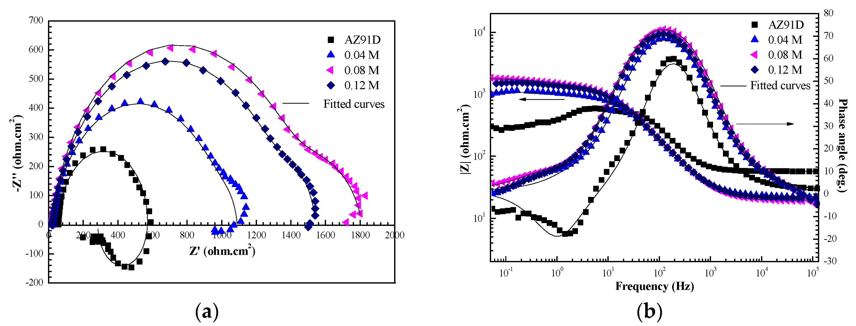
Figure 1. (a) Nyquist plots and (b) Bode plots for uncoated AZ91D substrate and Ca–P–V coated specimens at their open circuit with different NaVO3 concentrations in 3.5 wt % NaCl solution (the samples are not soaked in solution before tests). Symbols are experimental data and solid lines are fitting data.
Coatings 09 00379 g001
Figure 2. SEM morphologies of (a) single vanadium coating without Ca–P; (b) Ca–P coating without V and (c) Ca–P–V composite coating; (d) cross-sectional micrograph of Ca–P–V composite coating; (e) EDS analysis of Ca–P–V composite coating.
Coatings 09 00379 g002
Figure 3. XPS patterns of the Ca–P–V composite coating: (a) The survey spectrum; (b) high-resolution spectrum of Ca 2p; (c) high-resolution spectrum of Mg 2p; (d) high-resolution spectrum of P 2p; (e) high-resolution spectrum of V 2p; (f) high-resolution spectrum of O 1s.
Coatings 09 00379 g003
Figure 4. Schematic illustration of the formation mechanism of the Ca–P–V composite coating on AZ91D substrate: (a) dissolution of magnesium and evolution of hydrogen; (b) nuclei formation of CaHPO4·2H2O, Ca3(PO4)2, and Mg3(PO4)2; (c) conversion layer formed over the entire surface.
Coatings 09 00379 g004
Figure 5. The polarization curves of the uncoated AZ91D substrate and the Ca–P–V coated samples in 3.5 wt % NaCl solution after immersion for different days before tests.
Coatings 09 00379 g005
Figure 6. EIS plots for uncoated AZ91D substrate and Ca–P–V coated samples at their open circuit potential after immersion for different days in 3.5 wt % NaCl solution. (a) Nyquist plots; (b) Bode plots of |Z| vs. frequency; (c) Bode plots of Phase angle vs. frequency. (Symbols are experimental data and solid lines are fitting data. The subfigures in (a) are the equivalent circuit models of (1) the uncoated AZ91D substrate and (2) the Ca–P–V coated samples after immersion for 3 d.)
Coatings 09 00379 g006
Figure 7. SEM morphologies of the scratched Ca–P–V coatings in 3.5 wt % NaCl solution for different days: (a) 0 d; (b) 1 d; (c) 2 d; (d) 3 d; (e) 3 d.
Coatings 09 00379 g007
Figure 8. SEM-EDS results of the scratched samples: (a) Ca–P–V coating before immersion; (b) Ca–P–V coating after immersion for 2 d; (c) the uncoated AZ91D after immersion for 2 d in 3.5 wt % NaCl solution.
Coatings 09 00379 g008
Table 1. Contents of various elements obtained from EDS analysis of the Ca–P–V composite coating.
ElementsMgAlZnOCaPV
at. %19.22.70.163.04.310.10.6
wt %22.63.50.248.78.415.11.6
Table 2. Corrosion parameters of the AZ91D substrate and various conversion coatings derived from Figure 5. βa and βc are the cathodic and anodic Tafel slopes.
SamplesEcorr (V/SCE)βa(mV/dec)βc (mV/dec)Icorr (A/cm2)
0 d−1.59 ± 0.0284.3−71.79.1 × 10−6
1 d−1.53 ± 0.0388.1−69.11.39 × 10−6
2 d−1.48 ± 0.0198.1−64.01.04 × 10−6
3 d−1.45 ± 0.0295.7−65.13.84 × 10−7
AZ91D−1.55 ± 0.0142.3−462.81.56 × 10−4