Article

A Comparative Study of Multifunctional Coatings Based on Electrospun Fibers with Incorporated ZnO Nanoparticles

1
Engineering Department, Public University of Navarre, Campus Arrosadía S/N, 31006 Pamplona, Spain
2
Institute for Advanced Materials (INAMAT), Public University of Navarre, Campus Arrosadía S/N, 31006 Pamplona, Spain
3
Centre of Advanced Surface Engineering, AIN, 31191 Cordovilla, Spain
*
Author to whom correspondence should be addressed.
Coatings 2019, 9(6), 367; https://doi.org/10.3390/coatings9060367
Submission received: 13 May 2019 / Revised: 29 May 2019 / Accepted: 3 June 2019 / Published: 4 June 2019
(This article belongs to the Special Issue Coatings and Interfaces)

Abstract

:
In this work, polymeric fibers of polystyrene (PS) with incorporated ZnO nanoparticles have been deposited onto an aluminum alloy substrate (6061T6) by using the electrospinning technique. In order to optimize the deposition process, the applied voltage and flow rate have been evaluated in order to obtain micrometric electrospun fibers with a high average roughness and superhydrophobic behavior. Thermogravimetric analysis (TGA) has also been employed in order to corroborate the amount of ZnO incorporated into the electrospun fibers, whereas differential scanning calorimetry (DSC) has been performed in order to determine the glass transition temperature (Tg) of the polymeric electrospun fibers. In addition, a specific thermal treatment (Tg + 20 °C) of the synthesized electrospun fibers has been evaluated in the resultant corrosion resistance. A comparative study with previously reported results corresponding to polyvinyl chloride (PVC) fibers is carried out along this paper to show the changes in behavior due to the different compositions and fiber diameters. The coating has produced an important reduction of the corrosion current of the aluminum substrate in two orders of magnitude, showing also an important enhancement against pitting corrosion resistance. Finally, this deposition technique can be used as an innovative way for the design of both superhydrophobic and anticorrosive surfaces in one unique step over metallic substrates with arbitrary geometry.

1. Introduction

The two main experimental factors that directly affect the resultant surface wettability are the surface chemical composition (presence the functional groups with water repellent behavior) which controls the surface free energy and the microstructure, affecting the microscopic roughness [1]. According to this first point, most of the approaches are based on the incorporation of fluorine groups in the outer surface because these functional groups can effectively cause a lower surface free energy [2,3,4]. As for the second point, two main wetting models (Wenzel and Cassie-Baxter) are used to explain of the effect of surface textures on the non-wettability which is directly associated to the microscopic rough surface [5]. In the Wenzel mechanism the liquid totally punctures the roughness channels [6], whereas in the Cassie-Baxter mechanism the surface superhydrophobicity is associated to the air trapped underneath the liquid inside the grooves [7,8]. Recently, Szewczyk et al. have published a complete study that include electrospun coatings made of polyamide (PA), polyvinylidene fluoride (PVDF), polymethylmethacrylate (PMMA), poly lactic-co-glycolic acid (PLGA), polycarbonate (PC), polycaprolactone (PCL), and polystyrene (PS) [9]. The effects of fiber diameter, fiber density and liquid surface tension are taken into account. In general, the air trapped between fibers keeps the wetting behavior in the Cassie-Baxter regime, but transitions to the Wenzel state are reported for liquids with surface tension below 58 mN m−1. Moreover, although this study is limited to static conditions, we recognize that the complete characterization of the wettability should include the study of dynamic contact angles, as well as the investigation of the role played by the real contact surface and the contact border which can be relevant according to recent studies [10,11,12,13].
Among all the multiple methods for the design of water repellent surfaces, one novel technique which is showing a great interest in the scientific community is the electrospinning because it is a versatile and flexible low-cost process for producing ultrathin fibers from a wide variety of materials (mostly polymers) onto any type of surfaces with arbitrary geometry. In this deposition technique, diameter-tunable electrospun fibers can be perfectly obtained as a function of the nature of the selected polymeric solution with a desired viscosity, as well as other operating parameters, such as applied voltage, distance collector, and the flow rate [14,15]. In addition, electrospinning also offers additional advantages such as an easy-scalability, one step fabrication process, and possibility of obtaining multifunctional surfaces due to its great versatility [16]. A clear example related to these previous advantages can be found in [17] where electrospun functionalized films with an enhancement corrosion resistance and hydrophobicity has been obtained by using a combination of electrospinning and another deposition technique, such as chemical vapor deposition (CVD). According to this, in other works, hydrophobic or even superhydrophobic materials with tunable wettability have been developed as a function of a polymeric precursor with functional groups with a clearly water-repellent behavior, such as polystyrene (PS) or polyvinyl chloride (PVC) [18,19]. The main reason of this higher non-wettability property is associated to the fabrication of rougher surfaces in comparison with flat film deposition [13,20].
Other aspect to be remarked is that the implementation of superhydrophobic surfaces also can be used as a great potential for applications of anticorrosive protection and, due to this, several research papers are focused on the fabrication of superhydrophobic electrospun fiber-coated metal substrates with a long-time corrosion resistance [21,22]. More recent research has been based on the immobilization of corrosion inhibitors into the electrospun fibers for improving the corrosion resistance. In this sense, the electrospun fibers act as ideal hosts of a wide variety of corrosion inhibitors of different nature such as cerium chloride, lithium carbonate, 2-mercaptobenzothiazole or even metal oxide nanoparticles (TiO2, ZnO) [23,24,25,26]. In addition, the presence of this type of nanoparticles between the interstices of the electrospun fibers can increase the surface roughness as well as the air entrapment, and as a result, an important increase in the water repellent behavior and, thus, a considerable enhancement in the corrosion resistance is obtained. In this work, two polymeric precursors with intrinsic hydrophobic behavior by nature, such as polystyrene (PS) and polyvinyl chloride (PVC) have been selected for the fabrication of highly hydrophobic, or even superhydrophobic electrospun fibers which also act as efficient hosts of a specific corrosion inhibitor (ZnO nanoparticles) with the aim of designing an innovative way to produce anticorrosive surfaces. Finally, the effect of a heat treatment over the glass transition temperature (Tg + 20 °C) has been also evaluated for both polymers, increasing the resultant anticorrosion capacity of the aluminum metallic substrates.

2. Experimental Procedure

2.1. Reagents and Materials

Polystyrene (PS, (C8H8)n, Mw = 280,000 g/mol), polyvinyl chloride (PVC, (C2H3Cl)n, Mw = 80,000 g/mol), dimethylformamide (DMF) and tetrahydrofuran (THF) were provided by Sigma-Aldrich (Saint Louis, MO, USA). Zinc oxide (ZnO) nanoparticles in colloidal dispersion (50% in H2O) with an average particle size of 50 nm were purchased from Alfa Aesar (Haverhill, MA, USA). All chemicals were used without any further purification. The coatings have been formed upon aluminum substrates of AA6061T6 alloy.

2.2. Preparation of the Electrospun Coatings

The electrospun PS and PVC solutions were prepared by dissolving 3.2 g of each polymeric precursor (PS or PVC, respectively) in solvent mixtures of 10 mL of DMF and 10 mL of THF (1:1 solvent volume ratio) at room temperature and applying vigorous stirring (600 rpm) for 12 h. In this way, a homogeneous solution with a polymer concentration 15 wt % is obtained. The viscosity of the solvents was 0.92 mPa s for DMF and 0.55 mPa s in the case of THF (values provided by Sigma-Aldrich and corresponding to a working temperature of 20 °C). The final solution viscosity depends on the polymer concentration and the volume ratio between the solvents [27,28]. Liu et al. studied the electrospinnability of a 15 wt % PS solution with different solvent systems and they found out that the binary solvent system DMF/THF with 1:1 volume ratio provided a suitable viscosity for the electrospinning process [29]. Separately, a ZnO mixture was produced by adding 0.64 g of the ZnO colloidal dispersion into a mixture of 1 mL of DMF and 1 mL of THF at room temperature and under stirring (200 rpm) for 12 h. After this ZnO mixture was prepared, it was added to the previous polymeric solution and, in order to allow for an adequate mixing, vigorous stirring (600 rpm) was again applied for 2 h. The as-prepared solution was electrospun using an ND-ES 11/7 lab electrospinning unit (Nadetech Innovations S.L., Navarre, Spain).
The solution was loaded to a 5 mL syringe disposed horizontally and the distance between the capillary tip and the aluminum electrode used as collector was fixed at 15 cm. A 20-gauge needle with an inner diameter of 0.6 mm was used as the positive electrode for all the depositions. Several electrospinning experiments were conducted at various pump speeds and direct current (DC) voltages in order to optimize the values of flow rate and applied voltage that allow for the synthesis of very thin fibers with maximum hydrophobic behavior. All depositions were produced over a fixed period of time of 10 min. Finally, in all the experiments the electrospinning process was performed at room temperature (20 °C) and 40% relative humidity.

2.3. Characterization Techniques

The as-prepared nanocomposites were characterized by thermogravimetric analysis (TGA) with a Q500 (TA Instruments, Q500, New Castle, DE, USA) in air atmosphere with a flow of 90 mL/min under a heating rate of 10 °C/min. Through the measured TGA curves, the corresponding concentration of inorganic filler (ZnO) was estimated. Additionally, differential scanning calorimetry (DSC-25, TA Instruments, New Castle, DE, USA) in nitrogen atmosphere with a flow of 50 mL/min and a heating rate of 10 °C/min, was employed in order to determine the corresponding glass transition temperature in both nanocomposites.
Water contact angle (WCA) measurements were conducted on a CAM 100 contact angle goniometer (CAM 100, KSV Instruments, Burlington, VT, USA) using distilled water. The static water contact angle was measured 5 times at different sites and the representative samples were chosen to present the result.
AFM analyses have been performed in tapping mode using a Veeco Icon Dimension (Plainview, NY, USA) fitted with phosphorus (n) doped silicon tips of k-spring of 3 N/m and resonance frequencies going from 60–86 kHz. Two different areas have been scanned, 60 µm × 60 µm and 30 µm × 30 µm on each sample. Images have been treated using Gwyddion Software (version 2.53) for SPM data analysis [30]. In addition, scanning electron microscopy images (SEM) have been obtained by means of a Hitachi S4800 Field Emission SEM (Tokyo, Japan), running at 1 kV of acceleration voltage. The samples had been previously coated with an approximately 10 nm platinum layer in order to improve the conductivity of the sample and, hence, the resolution.

2.4. Corrosion Tests Analysis

Tafel polarization curves and pitting corrosion tests were performed using an Autolab Potentiostat/Galvanostat PGSTAT302N (Metrohm, Herisau, Switzerland). All corrosion tests were performed at room temperature and a 3.5 wt % NaCl aqueous solution was used as the supporting electrolyte. A conventional three-electrode cell was used, with the uncoated and coated Al electrodes as the working electrodes, silver chloride Ag–AgCl as the reference electrode and platinum as the counter electrode, respectively. The samples were immersed for 30 min in the NaCl electrolyte in order to ensure steady state before conducting the electrochemical experiments. Tafel polarization measurements were obtained by scanning the electrode potential from −150 to +150 mV at a scan rate of 1.5 mV·s−1, and the corrosion protection efficiency for the coatings (η) was calculated by the following equation [31,32]:
η   ( % ) = i 0 i c i 0 × 100 %
In this formula, i 0 corresponds to the corrosion current density of the uncoated aluminum electrode and i c corresponds to that of the coated aluminum sample, respectively. The pitting corrosion measurements were recorded by scanning the electrode potential from 0 up to +2 V at a scan rate of 0.15 mV·s−1 and reversing the scan direction when the current surpassed a cutoff value of 2.5 mA.

3. Results and Discussion

3.1. Fabrication of the Electrospun Coatings

First of all, one of the main parameters that play a key role in the resultant fiber diameter of the electrospun fibers is the applied voltage. Due to this, in a first step it has been analyzed the influence of the applied voltage over fiber diameter using as polymeric precursor polystyrene (PS). Four samples of the PS have been electrospun, keeping a fixed flow rate and varying the applied voltage at a fixed period of time of 10 min. More specifically, the flow rate was fixed at 1.5 mL/h and the samples were electrospun at 11, 13, 15, and 17 kV, respectively, as it can be appreciated in Figure 1 with their corresponding error bars. The experimental results indicate that the lowest fiber diameter was around 2 µm for an applied voltage of 11 kV. One aspect to remark is that non-fiber deposition was observed for voltage values equal to 10 kV. The reason for this is that with such low values of applied voltage, the electrostatic forces were not high enough to overcome the surface tension of the PS solution and no fiber jet was emitted, and due to this, the value of 11 kV has been chosen to be the lower limit of the applied voltage for the setup of experiments.
As a main conclusion derived from this initial study is that the fiber diameter of PS electrospun fibers is higher by increasing the applied voltage. This same effect matches with the results obtained by Huan et al. who observed the effect of the applied voltage over the morphological properties of PS fibers [33]. However, an aspect to remark is that the influence of the applied voltage on the resultant fiber diameter has not been perfectly defined yet. For example, Reneker and Chun [34] have demonstrated that there is not much effect of applied voltage on the diameter of electrospun polyethylene oxide (PEO) nanofibers. Some studies suggest that higher voltages facilitate the formation of large diameter fibers, like Bakar et al. who studied how polyacrylonitrile (PAN) electrospun nanofibers increased their diameter with increasing applied voltages [35]. Others suggest that higher voltages can increase the electrostatic repulsive force on the charged jet, thus narrowing the fiber diameter. For example, Yuan et al. [36] observed that polysulfone (PSF) electrospun fibers presented lower diameters when increasing the applied voltage. This same effect related to a decrease of the electrospun fibers diameter as a function of an increase of the applied voltage is also observed for polyvinyl chloride (PVC) as it has been demonstrate in our previous work [37]. Therefore it can be concluded that voltage does influence over the fiber diameter but it can lead to different effects depending on the polymer employed.
Other deposition parameter that plays a key role in the fiber diameter is the flow rate. However, for this specific parameter a same tendency is shown for different polymers of study, being possible to affirm that the electrospun fibers become thicker with higher flow rate values, and this is clearly matched with the literature [37,38]. In this work, it has been observed that the lowest flow rate for obtaining PS electrospun fibers was 0.9 mL/h, being possible to obtain electrospun fibers with a diameter of around 2 µm, whereas a flow rate of 0.6 mL/h was used for PVC electrospun fibers in order to obtain submicrometric electrospun fibers. To sum up and after this initial study, the experimental conditions for the fabrication of the PS electrospun fibers were fixed for an applied voltage of 11 kV and a flow rate of 0.9 mL/h and for PVC electrospun fibers were fixed for an applied voltage of 14 kV and a flow rate of 0.6 mL/h, respectively. In both cases, the distance between the capillarity tip and the collector was kept constant and equal to 15 cm, and the deposition time was fixed at 10 min for all the samples of study.

3.2. Wettability Properties

Once the electrospinning parameters have been optimized for minimizing the fiber diameter of the electrospun fibers, as it can be previously observed in Figure 1, the next step was to corroborate its corresponding water repellency behavior. In Figure 2 it can be appreciated their corresponding water contact angel (WCA) values for both electrospun fibers. It is important to remark that the experimental results indicate that PS electrospun fibers show a higher WCA values in comparison with PVC sample, being this value higher than 150° and, thus, showing a superhydrophobic behavior. According to this, the WCA value presents a mean value of 163° ± 3° for PS samples and 145° ± 2° for PVC samples, respectively. Figure 2a,b presents an optical image of the resultant water contact angle value, whereas the aspect of the electrospun fibers deposited onto a glass slide is presented in Figure 2c with a characteristic white coloration under the experimental fabrication conditions. Finally, the aspect of the water drop deposited onto the electrospun fibers is also presented in Figure 2d. Other key aspect is that during the WCA tests it was quite difficult to deposit the water drop onto the electrospun coatings. This effect can be explained because of the high surface roughness of produced coatings which increases the air entrapment between the fibers, thus improving the water repellency of the coating, according to the Cassie-Baxter wetting model.

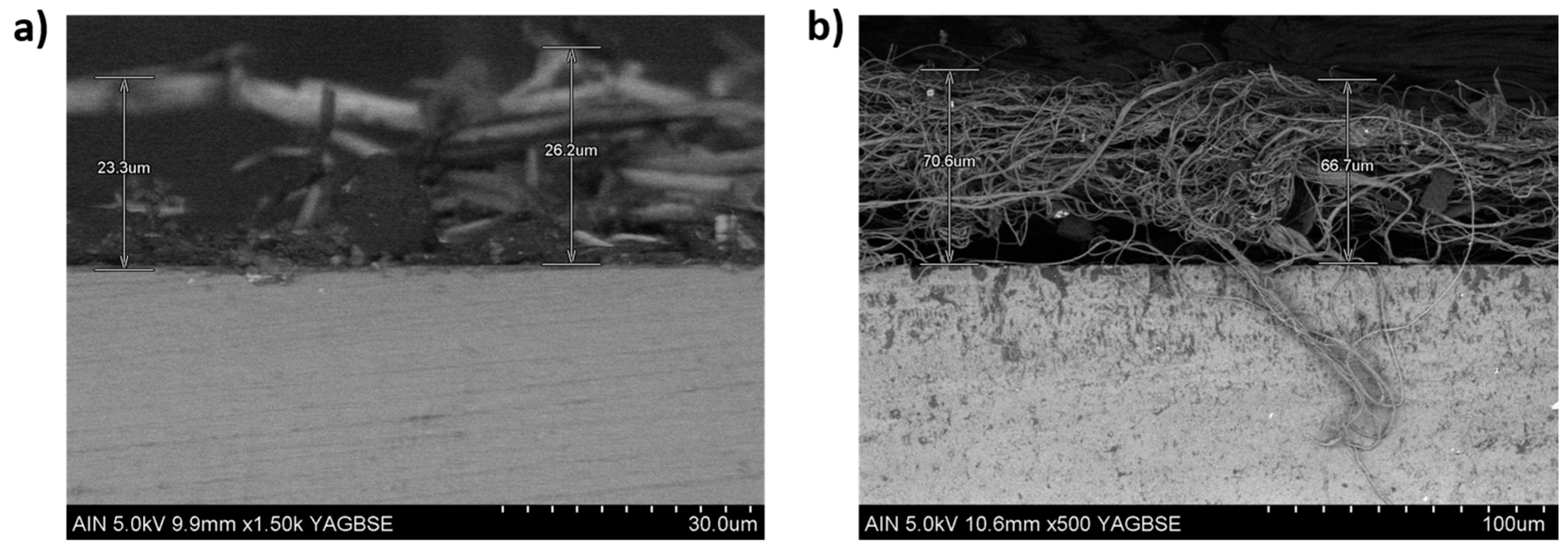
3.3. Morphology and Thickness Coating

Both field emission scanning electron microscopy (FE-SEM) and atomic force microscopy (AFM, Veeco Innova AFM, Veeco Instruments, Plainview, NY, USA) have been employed in order to characterize the morphology of the resultant electrospun fibers. In Figure 3, some SEM images of the electrospun coatings at different magnifications are presented. In both cases, a dense structure of entangled threads of different thicknesses between 2 and 4 µm have been observed for the PS samples (Figure 3a,b), whereas thinner electrospun fibers in a submicrometric range have been observed for PVC samples (Figure 3c,d) with a thickness diameter between 500 and 700 nm, respectively. This fact of fibers showing a variable diameter for both types of samples is also corroborated by AFM images, as it can be observed in Figure 4. In this sense, 2D AFM images with their corresponding profiles (three evaluation lines) clearly reveal that a bigger size in diameter fiber is obtained for PS samples (Figure 4a,b) in comparison with PVC samples (Figure 4c,d). In addition, the arithmetic average roughness Ra of the PS coating was found to be 505.7 nm which is higher than PVC coating with a value of 427.5 nm, respectively. This result is in concordance with the high value of the contact angle value (WCA) because an increase in the hydrophobicity is clearly obtained by the increment in the resultant surface roughness, and due to this the WCA values for PS samples are higher than PVC samples as it can be appreciated in the wettability properties.
Finally, the cross-section SEM images (see Figure 5) indicate a notorious difference in the resultant thickness coating for both samples under their specific experimental conditions fabrication, being around 25 µm for PS sample (Figure 5a) and 70 µm for PVC sample (Figure 5b), respectively.

3.4. Thermal Analysis

Firstly, the TGA thermal curves have been obtained for the two different as-prepared fibers (only polymer and polymer with ZnO nanoparticles), as it can be appreciated in the comparative TGA curves in Figure 6. According to this, a unique decomposition process is observed for only PS electrospun fibers (Figure 6a), whereas two decomposition processes have been observed for only PVC electrospun fibers (Figure 6b) which in both are related to the oxidation of the organic matrices. Once the complete decomposition of the organic component has been obtained, the corresponding inorganic residue (ZnO) is observed with a final weight of 4.39% for PS_ZnO sample and 1.34% for PVC_ZnO sample, respectively. This kind of thermal stability with ZnO fillers has been previously reported in ZnO-modified polymeric fibers [39].
Following, the DSC curves for both samples were measured in inert atmosphere with the aim of determining the corresponding glass transition temperature (Tg) for each nanocomposite, as it can be seen in Figure 7.
For PS samples (Figure 7a), two different phase transitions were obtained reflected in the slope change of the heat flow curve which is mainly ascribed to the glass transition temperature (Tg). The measured temperature for the first glass transition (102.7 °C for PS and 101.99 °C for PS_ZnO) is similar to the experimental one reported in previous works (around 100 °C) [39]. In first instance, it could be inferred from this result (first glass transition temperature) that the introduction of ZnO nanoparticles in the polystyrene fibers does not induce changes into the mobility of the polymeric chains and, thus, in the final Tg. Increments of 5−6 °C in Tg for PS_ZnO nanocomposites were identified through DSC measurements for concentrations of ZnO from 5% up to 30% [40]. Nevertheless, any remarkable change in Tg was observed for the bare polymer PS and the nanocomposite with ZnO. Additionally, a second glass transition was observed in the DSC curve. In this regard, the average diameter of the polymeric fibers represents a remarkable parameter to take into account in the analysis of the final glass transition temperatures detected. In fact, it was previously reported the increment of Tg with the mean diameter of polymeric PVA fibers through AFM measurements [41]. Finally, according to PVC samples (Figure 7b), the presence of ZnO nanoparticles in the fiber mat does not produce a relevant change in the Tg, being 82.27 °C for PVC and 82.36 °C for PVC_ZnO, as was previously reported in [37].

3.5. Anticorrosion Performance of Electrospun Fibers

The main goal of this study was to demonstrate that the anticorrosion performance of an aluminum substrate can be enhanced by utilizing electrospun PS and PS_ZnO nanocomposite films. In order to check if these coatings successfully improve this corrosion resistance, Tafel polarization and pitting corrosion tests were performed. These tests were firstly conducted over a bare aluminum 6061T6 sample as a reference to be later compared with the results from the different samples. Tafel polarization and pitting test results are shown in Figure 8. From the Tafel analysis it was found that the corrosion current density (icorr) for the bare aluminum substrate was 1.107 μA·cm−2 at a corrosion potential (Ecorr) of −0.856 V, with the cathodic (βc) and anodic (βa) Tafel constants equal to 150 and 56 mV/decade, respectively. Pitting corrosion tests allow for the determination of the moment when pitting appear, i.e., the electric potential above which the corrosion current starts increasing very rapidly. Scully et al. defined the pitting potential Ep as the potential above which the rising current permanently exceeded 10 μA [42]. According to this, the pitting potential of the uncoated aluminum sample was found to be −0.656 V.
After the anticorrosion behavior of the aluminum bare reference substrate was addressed, corrosion tests were performed over the coated samples with electrospun PS_ZnO and PVC_ZnO films in order to corroborate whether these coatings successfully enhance the corrosion resistance of the metallic substrate. Initially, in a first step, a thermal treatment was performed up to the glass transition temperature (Tg) in order to improve adherence between the fiber mat and the underlying metallic substrate. Then, in a second step, these samples were heated up 20 °C higher than the Tg with the aim of checking if the movement of the polymeric chains above Tg could lead to a better distribution of ZnO nanoparticles in between the fibers and, therefore, an improvement in the corrosion resistance of the electrospun coatings. The Tafel polarization curves are shown in Figure 9, whereas the experimental results are displayed in Table 1, respectively.
As it can be observed in Figure 9, the electrospun coatings with ZnO inclusions enhance the corrosion resistance of the aluminum substrate. All coatings reduced the corrosion current density in two orders of magnitude, from a value of 1.107 μA cm−2 in the case of bare aluminum substrate to a minimum of 0.010 μA·cm−2 or 0.009 μA·cm−2 in the case of the PS_ZnO and PVC_ZnO samples thermally treated (Tg + 20 °C), respectively. In addition, the protection efficiency (η) of the PS_ZnO and PVC_ZnO coatings heat-treated to the glass transition temperature of the polymer was found to be 93.95% and 95.12%, respectively. However, when the samples were heat treated 20 degrees over Tg (Tg + 20 °C), a maximum value of 99.10% or 99.19% have been obtained. As a main conclusion is that after conducting a heat treatment over the glass transition temperature, an excellent anticorrosion capacity was obtained which may be explained by a better distribution of ZnO nanoparticles between the interstices of the fiber mat.
After Tafel polarization measurements were performed, a pitting corrosion test was conducted over the PS_ZnO and PVC_ZnO electrospun coatings with a specific thermal treatment (Tg + 20 °C) for showing the maximum protection efficiency during the Tafel tests. The resultant curves from the pitting test are plotted in Figure 10, where the behavior of the coating against localized corrosion is compared to that of the reference bare aluminum. The pitting potential Ep, which was determined following the same methodology as Scully et al. [42], was found to be –0.398 V (PS_ZnO), −0.341 V (PVC_ZnO), and −0.656 V (reference uncoated aluminum substrate), respectively. Therefore, the utilization of the electrospun coating clearly enhances the resistance of aluminum against localized corrosion.
Furthermore, it was observed that once pitting starts the current growing rate is effectively reduced, as the current cutoff of 2.5 mA was reached at 0.090 V in the case of PS_ZnO coating or 0.015 V in the case of PVC_ZnO while it was reached at −0.538 V in case of bare aluminum substrate. This pitting current increase rate (vpitting) is determined as the slope of the polarization curve in the region between the pitting potential (Ep) and the potential at which the current cutoff value of 2.5 mA is reached (Ecutoff). A straight-line approximation approach can be used to estimate this value [32]:
v pitting = 2.5 0.01 E cutoff E p   ( mA / V )
Finally, the pitting current increase rate was reduced from 21.10 mA·V−1 (bare aluminum substrate) to 5.10 mA·V−1 (PS_ZnO coating) or 6.99 mA·V−1 (PVC_ZnO coating), which represents an efficiency of 75.83% (PS_ZnO) or 66.9% (PVC_ZnO) coatings. The pitting test results are displayed in Table 2. To sum up, as it can be seen in the experimental results, the utilization of both PS_ZnO and PVC_ZnO successfully improved the resistance of aluminum against localized (pitting) corrosion, which is one the main corrosion mechanism affecting aluminum alloys.

4. Conclusions

In the present study, we have successfully deposited electrospun fibers with incorporated ZnO nanoparticles by using electrospinning technique. This deposition method makes possible the production of fibers with a good control over the resultant morphology as a function of the polymeric precursor and the operating parameters. In a first step, two different polymeric precursors, such as polystyrene (PS) and polyvinyl chloride (PVC), have been selected for showing hydrophobic behavior by nature. After that, an initial study has been performed in order to evaluate the effect of the applied voltage in the morphology of the electrospun fibers, making possible the fabrication of superhydrophobic surfaces (WCA of 163 °C) for PS samples or almost superhydrophobic behavior (WCA of 145 °C) for PVC samples. In addition, the electrospun fibers show a micrometric dimension for PS samples and sub-micrometric dimension for PVC samples (corroborated by AFM and SEM analysis). Other aspect to remark is that ZnO nanoparticles which act as corrosion inhibitors have also incorporated in the electrospun fibers (corroborated by TGA) which play a key role in the corrosion resistance of the electrospun coating (corroborated by Tafel curves and pitting corrosion tests). Finally, a thermal treatment at Tg + 20 °C has been performed for both samples (PS_ZnO and PVC_ZnO), showing the maximum protection efficiency during the Tafel tests. To sum up, the combination of both polymeric precursors (PS and PVC) with ZnO nanoparticles under a specific experimental conditions and thermal treatment can be used as an innovative way for the implementation of superhydrophobic or highly hydrophobic and anticorrosive surfaces, being of great interest for other different industrial applications, such as energy, marine, self-cleaning or anti-icing surfaces, among others.

Author Contributions

Conceptualization, A.I. and P.J.R.; Methodology, A.I. and P.J.R.; Validation, A.I., P.J.R., and R.R.; Formal Analysis, A.I., P.J.R., S.L. and J.F.P.; Investigation, A.I., P.J.R., S.L., J.F.P. and R.R.; Writing—Original Draft Preparation, P.J.R. and A.I.; Writing—Review and Editing, A.I., P.J.R. and R.R.; Supervision, P.J.R. and R.R.

Funding

This research was funded by the Spanish Science, Innovation and Universities Ministry–FEDER Proyecto Retos de la Sociedad RTI2018-096262-B-C41 (MAI-TAI project) and by the Public University of Navarra collaboration research grant PRO-UPNA 18 (6107).

Acknowledgments

The authors would like to express their gratitude to Nadetech Inc. for the tune-up of the robot used for the deposition of the nanocoatings.

Conflicts of Interest

The authors declare no conflict of interest.

References

  1. Fürstner, R.; Barthlott, W.; Neinhuis, C.; Walzel, P. Wetting and self-cleaning properties of artificial superhydrophobic surfaces. Langmuir 2005, 21, 956–961. [Google Scholar] [CrossRef] [PubMed]
  2. Rivero, P.J.; Maeztu, J.D.; Berlanga, C.; Miguel, A.; Palacio, J.F.; Rodriguez, R. hydrophobic and corrosion behavior of sol-gel hybrid coatings based on the combination of TiO2 NPs and fluorinated chains for aluminum alloys protection. Metals 2018, 8, 1076. [Google Scholar] [CrossRef]
  3. Lei, H.; Xiao, J.; Xiong, M.; Zheng, L.; Zhuang, Q. Fluorine-free superhydrophobic coatings based on silicone and functionalized colloidal silica. Coatings 2019, 9, 159. [Google Scholar] [CrossRef]
  4. Maeztu, J.D.; Rivero, P.J.; Berlanga, C.; Bastidas, D.M.; Palacio, J.F.; Rodríguez, R. Effect of graphene oxide and fluorinated polymeric chains incorporated in a multilayered sol-gel nanocoating for the design of corrosion resistant and hydrophobic surfaces. Appl. Surf. Sci. 2017, 419, 138–149. [Google Scholar] [CrossRef]
  5. Lin, Y.; Chen, H.; Wang, G.; Liu, A. Recent progress in preparation and anti-icing applications of superhydrophobic coatings. Coatings 2018, 8, 208. [Google Scholar] [CrossRef]
  6. Wenzel, R.N. Resistance of solid surfaces to wetting by water. Ind. Eng. Chem. 1936, 28, 988–994. [Google Scholar] [CrossRef]
  7. Cassie, A.B.D.; Baxter, S. Wettability of porous surfaces. Trans. Faraday Soc. 1944, 40, 546–551. [Google Scholar] [CrossRef]
  8. Milne, A.J.B.; Amirfazli, A. The Cassie equation: How it is meant to be used. Adv. Colloid Interface Sci. 2012, 170, 48–55. [Google Scholar] [CrossRef]
  9. Szewczyk, P.K.; Ura, D.P.; Metwally, S.; Knapczyk-Korczak, J.; Gajek, M.; Marzec, M.M.; Bernasik, A.; Stachewicz, U. Roughness and fiber fraction dominated wetting of electrospun fiber-based porous meshes. Polymers 2019, 11, 34. [Google Scholar] [CrossRef]
  10. Gao, L.; McCarthy, T.J. Wetting 101°. Langmuir 2009, 25, 14105–14115. [Google Scholar] [CrossRef]
  11. Gao, L.; McCarthy, T.J. An attempt to correct the faulty intuition perpetuated by the Wentzel and Cassie “laws”. Langmuir 2009, 25, 7249–7255. [Google Scholar] [CrossRef] [PubMed]
  12. Urata, C.; Masheder, B.; Cheng, D.F.; Miranda, D.F.; Dunderdale, G.J.; Miyamae, T.; Hozumi, A. Why can organic liquids move easily on smooth alkyl-terminated surfaces? Langmuir 2014, 30, 4049–4055. [Google Scholar] [CrossRef] [PubMed]
  13. Yuan, Y.; Choi, S.-O.; Kim, J. Analysis of contact area between water and irregular fibrous surface for prediction of wettability. RSC Adv. 2016, 6, 73313–73322. [Google Scholar] [CrossRef] [Green Version]
  14. Li, D.; Xia, Y. Electrospinning of nanofibers: Reinventing the wheel? Adv. Mater. 2004, 16, 1151–1170. [Google Scholar] [CrossRef]
  15. Sill, T.J.; von Recum, H.A. Electrospinning: Applications in drug delivery and tissue engineering. Biomaterials 2008, 29, 1989–2006. [Google Scholar] [CrossRef] [PubMed]
  16. Rivero, P.J.; Garcia, J.A.; Quintana, I.; Rodriguez, R. Design of nanostructured functional coatings by using wet-chemistry methods. Coatings 2018, 8, 76. [Google Scholar] [CrossRef]
  17. Rivero, P.J.; Yurrita, D.; Berlanga, C.; Palacio, J.F.; Rodríguez, R. Functionalized electrospun fibers for the design of novel hydrophobic and anticorrosive surfaces. Coatings 2018, 8, 300. [Google Scholar] [CrossRef]
  18. Ghochaghi, N.; Taiwo, A.; Winkel, M.; Dodd, B.; Mossi, K.; Tepper, G. Electrospun polystyrene coatings with tunable wettability. J. Appl. Polym. Sci. 2015, 132, 41592. [Google Scholar] [CrossRef]
  19. Asmatulu, R.; Ceylan, M.; Nuraje, N. Study of superhydrophobic electrospun nanocomposite fibers for energy system. Langmuir 2011, 27, 504–507. [Google Scholar] [CrossRef]
  20. Bormashenko, E.; Starov, V. Impact of surface forces on wetting or hierarchical surfaces and contact angle hysteresis. Colloid Polym. Sci. 2013, 291, 343–346. [Google Scholar] [CrossRef]
  21. Cui, M.; Xu, C.; Shen, Y.; Tian, H.; Feng, H.; Li, J. Electrospinning superhydrophobic nanofibrous poly(vinylidene fluoride)/stearic acid coatings with excellent corrosion resistance. Thin Solid Films 2018, 657, 88–94. [Google Scholar] [CrossRef]
  22. Zhao, Y.; Zhang, Z.; Yu, L. Corrosion protection of carbon steel by electrospun film containing polyaniline microfibers. React. Funct. Polym. 2016, 102, 20–26. [Google Scholar] [CrossRef]
  23. Dieleman, C.D.; Denissen, P.J.; Garcia, S.J. Long-term active corrosion protection of damaged coated-AA2024-T3 by embedded electrospun inhibiting nanonetworks. Adv. Mater. Interfaces 2018, 5, 1800176. [Google Scholar] [CrossRef]
  24. Dong, Y.; Li, S.; Zhou, Q. Self-healing capability of inhibitor-encapsulating polyvinyl alcohol/polyvinylidene fluoride coaxial nanofibers loaded in epoxy resin coatings. Prog. Org. Coat. 2018, 120, 49–57. [Google Scholar] [CrossRef]
  25. Radwan, A.B.; Mohamed, A.M.A.; Abdullah, A.M.; Al-Maadeed, M.A. Corrosion protection of electrospun PVDF–ZnO superhydrophobic coating. Surf. Coat. Technol. 2016, 289, 136–143. [Google Scholar] [CrossRef]
  26. Kim, J.; Mousa, H.M.; Park, C.H.; Kim, C.S. Enhanced corrosion resistance and biocompatibility of AZ31 Mg alloy using PCL/ZnO NPs via electrospinning. Appl. Surf. Sci. 2017, 396, 249–258. [Google Scholar] [CrossRef]
  27. Firouzi, A.; Impagnatiello, A.; Del Gaudio, C.; Lamastra, F.R.; Bianco, A.; Montesperelli, G. Electrospun protective self-healing coatings for light alloys: A better understanding of the intrinsic potential of the technology. J. Appl. Polym. Sci. 2015, 132, 42728. [Google Scholar] [CrossRef]
  28. Tarus, B.; Fadel, N.; Al-Oufy, A.; El-Messiry, M. Effect of polymer concentration on the morphology and mechanical characteristics of electrospun cellulose acetate and poly (vinyl chloride) nanofiber mats. Alex. Eng. J. 2016, 55, 2975–2984. [Google Scholar] [CrossRef] [Green Version]
  29. Liu, W.; Huang, C.; Jin, X. Electrospinning of grooved polystyrene fibers: Effect of solvent systems. Nanoscale Res. Lett. 2015, 10, 237. [Google Scholar] [CrossRef] [PubMed]
  30. Nečas, D.; Klapetek, P. Gwyddion: An open-source software for SPM data analysis. Cent. Eur. J. Phys. 2012, 10, 181–188. [Google Scholar] [CrossRef]
  31. Abd El Haleem, S.M.; Abd El Wanees, S.; Bahgat, A. Environmental factors affecting the corrosion behaviour of reinforcing steel. VI. Benzotriazole and its derivatives as corrosion inhibitors of steel. Corros. Sci. 2014, 87, 321–333. [Google Scholar] [CrossRef]
  32. Zampetti, E.; Pantalei, S.; Scalese, S.; Bearzotti, A.; De Cesare, F.; Spinella, C.; Macagnano, A. Biometic sensing layer based on electrospun conductive polymer webs. Biosens. Bioelectron. 2011, 26, 2460–2465. [Google Scholar] [CrossRef] [PubMed]
  33. Huan, S.; Liu, G.; Han, G.; Cheng, W.; Fu, Z.; Wu, Q.; Wang, Q. Effect of experimental parameters on morphological, mechanical and hydrophobic properties of electrospun polystyrene fibers. Materials 2015, 8, 2718–2734. [Google Scholar] [CrossRef]
  34. Reneker, D.H.; Chun, I. Nanometre diameter fibres of polymer, produced by electrospinning. Nanotechnology 1996, 7, 216–223. [Google Scholar] [CrossRef] [Green Version]
  35. Bakar, S.S.S.; Fong, K.C.; Eleyas, A.; Nazeri, M.F.M. Effect of voltage and flow rate electrospinning parameters on polyacrylonitrile electrospun fibers. IOP Conf. Ser. Mater. Sci. Eng. 2018, 318, 012076. [Google Scholar] [CrossRef]
  36. Yuan, X.; Zhang, Y.; Dong, C.; Sheng, J. Morphology of ultrafine polysulfone fibers prepared by electrospinning. Polym. Int. 2004, 53, 1704–1710. [Google Scholar] [CrossRef]
  37. Iribarren, A.; Rivero, P.J.; Berlanga, C.; Larumbe, S.; Miguel, A.; Palacio, J.F.; Rodriguez, R. Multifunctional protective PVC–ZnO nanocomposite coatings deposited on aluminum alloys by electrospinning. Coatings 2019, 9, 216. [Google Scholar] [CrossRef]
  38. Megelski, S.; Stephens, J.S.; Chase, D.B.; Rabolt, J.F. Micro- and nanostructured surface morphology on electrospun polymer fibers. Macromolecules 2002, 35, 8456–8466. [Google Scholar] [CrossRef]
  39. Chae, D.W.; Kim, B.C. Characterization on polystyrene/zinc oxide nanocomposites prepared from solution mixing. Polym. Adv. Technol. 2005, 16, 846–850. [Google Scholar] [CrossRef]
  40. Ma, C.-C.M.; Chen, Y.-J.; Kuan, H.-C. Polystyrene nanocomposite materials—Preparation, mechanical, electrical and thermal properties, and morphology. J. Appl. Polym. Sci. 2006, 100, 508–515. [Google Scholar] [CrossRef]
  41. Wang, W.; Barber, A.H. Measurement of size-dependent glass transition temperature in electrospun polymer fibers using AFM nanomechanical testing. J. Polym. Sci. 2012, 50, 546–551. [Google Scholar] [CrossRef]
  42. Scully, J.R.; Budiansky, N.D.; Tiwary, Y.; Mikhailov, A.S.; Hudson, J.L. An alternate explanation for the abrupt current increase at the pitting potential. Corros. Sci. 2008, 50, 316–324. [Google Scholar] [CrossRef]
Figure 1. (a) Evolution of the fiber diameter as a function of the applied voltage (11, 13, 15, and 17 kV) at a fixed flow rate of 1.5 mL/h; (b) Aspect of the electrospun coating based on the deposition of PS electrospun fibers with a characteristic white coloration onto an aluminum reference substrate.
Coatings 09 00367 g001
Figure 2. Optical image of the water contact angle (WCA) value for PS (a) and PVC (b) samples; (c) Aspect of the electrospun fibers with a characteristic white coloration deposited onto a standard microscope glass slide; (d) A picture of the water drop onto the electrospun fibers.
Coatings 09 00367 g002
Figure 3. SEM images of the PS electrospun fibers (a,b) and PVC electrospun fibers (c,d) at different scale bar of 1000× and 2000×, respectively.
Coatings 09 00367 g003aCoatings 09 00367 g003b
Figure 4. 2D-AFM images for a dimension of 60 × 60 µm2 of the PS electrospun fibers (a,b) and PVC electrospun fibers (c,d) with their corresponding profiles.
Coatings 09 00367 g004
Figure 5. Cross-sectional SEM image of the PS (a) and PVC (b) electrospun fiber coating with their corresponding thickness.
Coatings 09 00367 g005
Figure 6. Comparative TGA curves for PS and PS_ZnO samples (a); TGA curves for PVC and PVC_ZnO samples (b), respectively.
Coatings 09 00367 g006
Figure 7. Comparative DSC curves for PS and PS_ZnO samples (a) and TGA curves for PVC and PVC_ZnO samples (b), respectively.
Coatings 09 00367 g007
Figure 8. Tafel plot (a) and pitting corrosion curve (b) for the reference aluminum bare substrate in 3.5 wt % NaCl aqueous solution.
Coatings 09 00367 g008
Figure 9. Tafel plots corresponding to the Al bare substrate and the Al samples coated with electrospun PS_ZnO and PVC_ZnO electrospun fibers which have been thermally treated and tested in 3.5 wt % NaCl aqueous solution.
Coatings 09 00367 g009
Figure 10. Pitting test plots for the Al bare substrate and the composite PVC–ZnO coating tested in 3.5 wt % NaCl aqueous solution.
Coatings 09 00367 g010
Table 1. Tafel analysis for uncoated Al substrate, PS_ZnO and PVC_ZnO samples thermally treated and tested in 3.5 wt % NaCl aqueous solutions.
Sampleβa (mV/dec)βc (mV/dec)icorr (µA/cm2)Ecorr (V)Efficiency (%)
Bare Al561501.107−0.856
PS (Tg)71670.067−0.82293.95
PS_ZnO (Tg + 20 °C)101970.010−0.90999.10
PVC (Tg)140960.054−0.82695.12
PVC_ZnO (Tg + 20 °C)1751590.009−0.79399.19
Table 2. Pitting test results for the bare Al substrate and both PS_ZnO and PVC_ZnO coating, tested in 3.5 wt % NaCl aqueous solutions.
SampleEp (V)Ecutoff (V)vpitting (mA/V)
Bare Al−0.656−0.53821.10
PS_ZnO (Tg + 20 °C)−0.3980.0905.10
PVC_ZnO (Tg + 20 °C)−0.3410.0156.99

