Communication

Adhesive Hybrid SiO2.01C0.23Hx Nanoparticulate Coating on Polyethylene (PE) Separator by Roll-to-Roll Atmospheric Pressure Plasma

1
Department of Physics, Donghua University (DHU), Shanghai 201600, China
2
Functional Materials Research Institute, Donghua University (DHU), Shanghai 201600, China
3
Member of Magnetic Confinement Fusion Research Centre, Ministry of Education, Shanghai 201600, China
*
Authors to whom correspondence should be addressed.
Coatings 2019, 9(3), 190; https://doi.org/10.3390/coatings9030190
Submission received: 25 February 2019 / Revised: 8 March 2019 / Accepted: 12 March 2019 / Published: 14 March 2019
(This article belongs to the Special Issue Surface Plasma Treatments)

Abstract

:
For the ever-increasing demand for highly safe lithium-ion batteries (LIBs), the common sol-gel process provides heat-resistance to separators with an inorganic coating, where the adhesion to the separator is the key to safety and stability. In this paper, we present a SiO2.01C0.23Hx-coated polyethylene (PE) separator through a roll-to-roll atmospheric plasma-enhanced chemical vapor deposition (R2R-APECVD) of hexamethyldisiloxane (HMDSO)/Ar/O2. The adhesion strength of SiO2.01C0.23Hx-coated PE was tested by peel-off test and found to be higher than that of the commercial Al2O3-coated separator (0.28 N/mm vs. 0.06 N/mm). Furthermore, the SiO2.01C0.23Hx-coated PE separator showed better electrochemical performance in C-rate and long term cycle tests. FTIR, SEM, and XPS analysis indicate that the increased adhesion and electrochemical performance are attributed to the inner hybrid SiO2.01C0.23Hx coating with organic and inorganic components.

1. Introduction

Compared with lead-acid, nickel-cadmium, and nickel-hydrogen batteries, LIBs have the advantages of relatively high energy density, low pollution, and long lifespan, which have potential applications in electromobile and energy storage systems [1,2,3,4]. Extensive research efforts have been devoted to achieving the high energy density, enhanced C-rate, and superior safety features required to obtain short charging times and long driving distances for electric vehicles [5,6,7,8]. In addition to the development of novel and advanced electrodes and electrolytes, many studies have focused on improving the performance of separators [9,10,11].
In LIBs, the separator ensures electrical insulation and provides ion channels between the positive and negative electrodes [12]. It also provides safety through the closing of pores during thermal runaway. Coating separators with inorganic particles, such as Al2O3, SiO2, and TiO2, is a feasible and affordable way to achieve high-efficiency and -safety cells. However, the ordinary wet or sol-gel coating method usually causes problems in adhesion between the separators and the nanoparticles. Some of the coatings could detach from the separator surface and cause non-uniform impedance of the separator, which diminishes the electrochemical performance [13,14,15,16]. The performance of the coated separator also affects the capacity and cycle performance of the LIBs directly [17,18]. In addition, wet coatings with a binder usually involve wet processes, which are relatively complicated and environmental unfriendly [19,20]. Chemical vapor deposition (CVD) of SiO2 and atomic layer deposition (ALD) of Al2O3 or TiO2 are novel methods with promising performances using a dry process conducted in a vacuum chamber for the preparation of composite separators or electrodes [21,22,23]. However, it is necessary to seek out more eco-efficient separator coating manufacturing processes to ensure the safety of LIBS.
Recently, non-thermally reactive atmospheric pressure plasma has attracted much attention for its simplicity and flexibility as a dry method of film deposition [23,24,25,26]. Plasma is an ionized gas composed of positive charged ions, negative charged ions, electrons, and radicals which have high reactive energy [27,28]. It can provide a unique environment for chemical reactions and film growth, which is distinct from typical condensed chemical reactions driven by a single heat source. All the reactions occur at low gas temperature and far from chemical equilibrium. This method shows great potential in industrial applications for producing temperature-sensitive substrate coatings.
In our previous work, SiOxCyHz or TiO2 nanoparticulate films have been successfully obtained by atmospheric pressure plasma-enhanced chemical vapor deposition (AP-PECVD) [29,30]. The purpose of this study is to investigate the structure and composition of the nanoparticulate coating and to obtain detailed information of the interfacial adhesion between the nanoparticulates coating and the PE separator by scanning electron microscopy (SEM), attenuated total reflection Fourier transform infrared spectroscopy (ATR-FTIR), X-ray photoelectron spectroscopy (XPS), and the peel-off test. There have been some studies that reported using atmospheric plasma to introduce hydrophilicity to the separator and increase Al2O3 adhesion with the separator [31]. We fail to find similar reports of AP-PECVD of hybrid nanoparticulate coating with increased adhesion. Therefore, we used Al2O3 coating as a comparison experiment. A noticeably improved adhesion strength was obtained and ascribed to the surface and inner SiO2.01C0.23Hx nanoparticulate coating. A better cell performance of C-rate and cycling than that with Al2O3 coating was achieved.

2. Materials and Methods

A commercial PE separator (12 μm thickness) was passed through the plasma zone at a controlled speed of 30 mm/min in a roll-to-roll way. The SiOxCyHz nanoparticulate coating on PE separator was directly achieved by modulating the hexamethyldisiloxane (HMDSO)/O2/Ar plasma system (flow rate in mL/min: 18/18/1600) for 3 min. Ar (99.990%) and O2 (99.500%) was purchased from Shanghai Shenzhong Gas Co., Ltd (Shanghai, China). HMDSO was purchased from Merck-Schuchardt (Hohenbrunn, Germany). The plasma zone was 50 mm × 50 mm and generated by a discharge power source of 13 kHz and 10 W. Al2O3 particle-coated PE (30 μm thickness; 5 μm coating layer:) was used for comparison. The commercial Al2O3 particle-coated separator was purchased from Shenzhen Senior New Energy Material Co., Ltd (Shenzhen, China).
The adhesion strength between the coated layer and the PE separator was measured through the peel-off test: 3M adhesive tape with 19 mm wide and 90 mm long (Scotch 600, 3M Material Technology Co.,Ltd., Suzhou, China) was attached to the separator and then pressed on evenly with a metal roller of 2 kg. The sticky tape was detached by peeling at an angle of 180° with a constant displacement rate of 100 mm/min. In order to guarantee the reproducibility of the test, we conducted the test at least three times for each sample and calculated the average adhesion strength.
The chemical structure of the separators was measured by attenuated total reflectance Fourier-transform infrared spectroscopy (Nicolet 6700 at 4 cm−1 spectral resolution, ThermoFisher Scientific, Waltham, MA, USA). The surface and cross-section morphologies were investigated by FE-SEM (S-4800, Hitachi, Tokyo, Japan). Qualitative analysis of the elemental composition of the membrane surface was analyzed by XPS (Escalab 250Xi, ThermoFisher Scientific, Waltham, MA, USA). In order to avoid the influence of the etching process or native layer of PE on the results, we performed the XPS test of the nanoparticles on quartz and 3-min-coated PE. We found that their XPS results are close, so it is reasonably deduced that the oxide observed for silicon and carbon is not from the native surface layer. A cleaning sputtering was done before the tests to remove the surface later of oxide.
Electrochemical properties were measured with coin-type LiFePO4/Li half-cells (CR2032, Shenzhen Kejing Star Technology Co., Ltd, Shenzhen, China). Coin cells were assembled by sandwiching the separators between the lithium metal anode and LiFePO4 cathode. The cathode was prepared by casting a N-methyl-2-pyrrolidone (NMP)-based slurry (LiFePO4:acetylene black: Polyvinylidene fluoride (PVDF) = 8:1:1 by weight) on aluminum foil (14 μm thickness), followed by drying at 110 °C for 12 h under vacuum. Charge–discharge cycling tests of the lithium-ion cells were conducted at various C-rates over the voltage range from 2.5 to 4.2 V using a battery test system (LAND CT2001A).

3. Results and Discussions

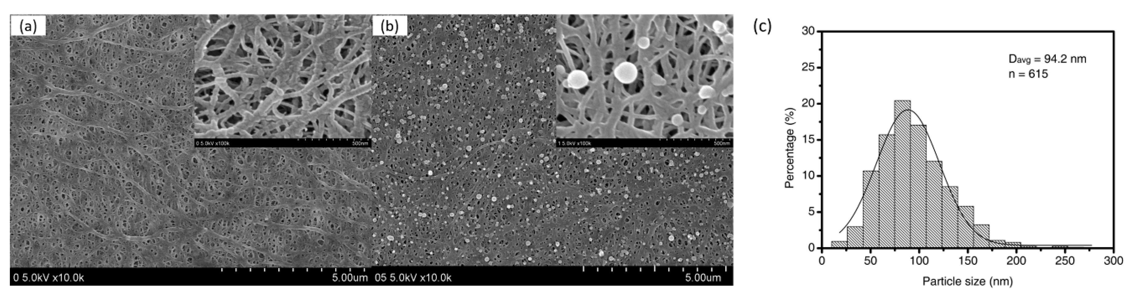
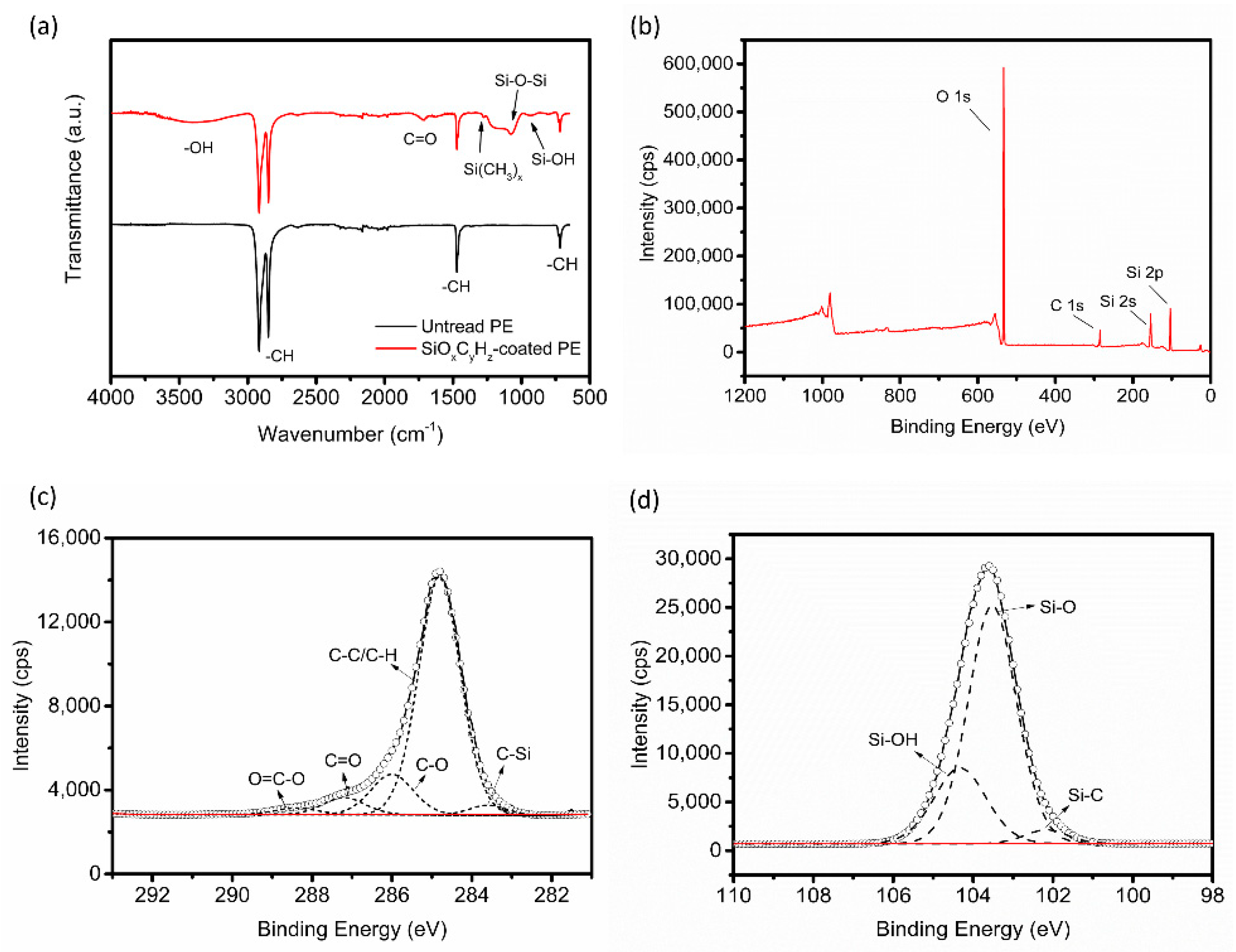
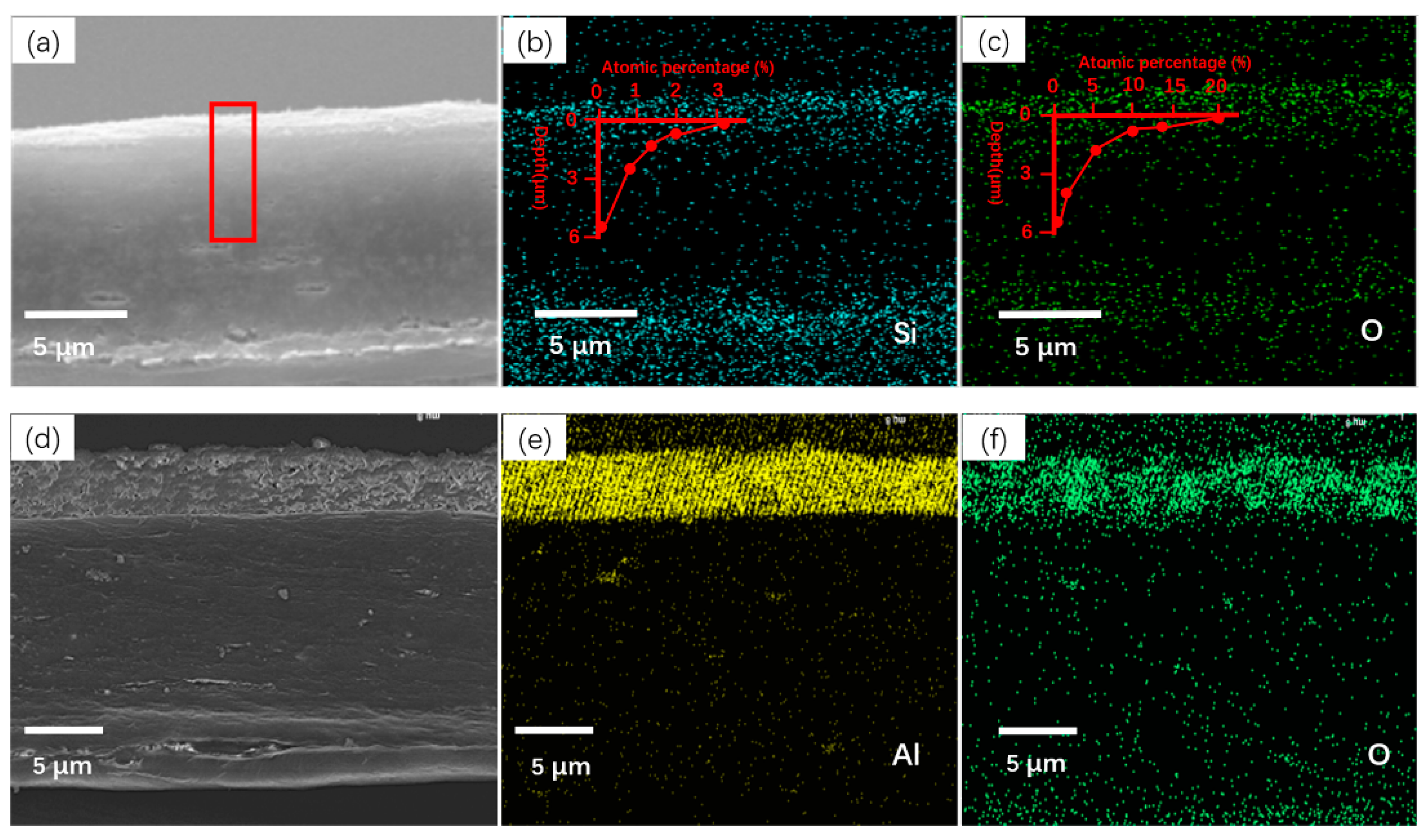
3.1. Morphological and Compositional Changes

The morphological and composition changes in the PE separators were characterized using FE-SEM, ATR-FTIR, and XPS. As shown in Figure 1a, the surface of the pristine PE consists of interlaced fibers and submicron pores, which is a typical morphology derived from wet processing. Figure 1b clearly shows that many nanoparticles were uniformly coated on the PE surface and closely interconnected on the fibers. We add two high magnification SEMs into Figure 1a,b (inset) for observing the pore and coated nanoparticles in detail. The particle sizes range from approximately 20 to 250 nm and the average diameter was 94.2 nm (Figure 1c).
Figure 2a shows the spectra of the untreated and plasma-coated PE through the ATR-FTIR. In the untreated PE separator, the strong bands at 2916 and 2849 cm−1 are assigned to asymmetric and symmetric CH2 stretching vibrations, respectively. The peaks at 1471 and 714 cm−1 are assigned to CH2 bending deformation and rocking deformation, respectively. After the deposition process, new Si-, C-, or O-based functional groups are present. The plasma-coated PE displays bands on 1077 and 930 cm−1 corresponding to Si–O–Si asymmetric stretching vibrations and Si–OH stretching, respectively. The broad band from 3100–3700 cm−1 is attributed to OH stretching in the Si–OH or C–OH groups [32]. These results confirm the successful introduction of functional groups like SiOx, Si(CH3)x, Si–OH, and C–OH into the PE separator.
According to the XPS in Figure 2b, the formula of the nanoparticulate film on PE can be written as SiO2.01C0.23Hx (Si 2p: 30.8%, C 1s: 7.1%, O 1s: 62.1%). The fitted C 1s and Si 2p spectra are presented in Figure 2c,d and display inorganic bands of SiO2 and SiOx, organic bands of C–O, C–C, and C=O, as well as a Si–C hybrid band. The percentage of the organic component (C–O, C–C, and C=O) and hybrid component (Si–C) according to the fitted C spectrum is 95% and 5%, respectively, while that of the inorganic and hybrid components in fitted Si 2p spectrum is 28% and 72%, respectively. Thus, it is reasonably deduced that the SiO2.01C0.23Hx nanoparticulate coating is mostly composed of inorganic components like SiO2 and small amount of organic components like C–O, C–C, and C=O, as well as hybrid structures like Si–C, which helps to improve the adhesion performance of the coating.
The nanoparticulate distribution on the cross-section of separators was identified using energy dispersive X-ray spectroscopy (EDS). As shown in Figure 3a, the plasma-coated film on PE is difficult to discern. However, the atomic percentage of Si and O are very high, near the surface of plasma-coated PE, and gradually decrease with depth into the center, confirming that the coating is thin and reaches into the inner fibers. As displayed in Figure 3d–f, there is a distinct boundary line between the Al2O3 coating and the PE. The thickness of the Al2O3 layer is about 5 μm, and Al and O are concentrated on the PE surface.

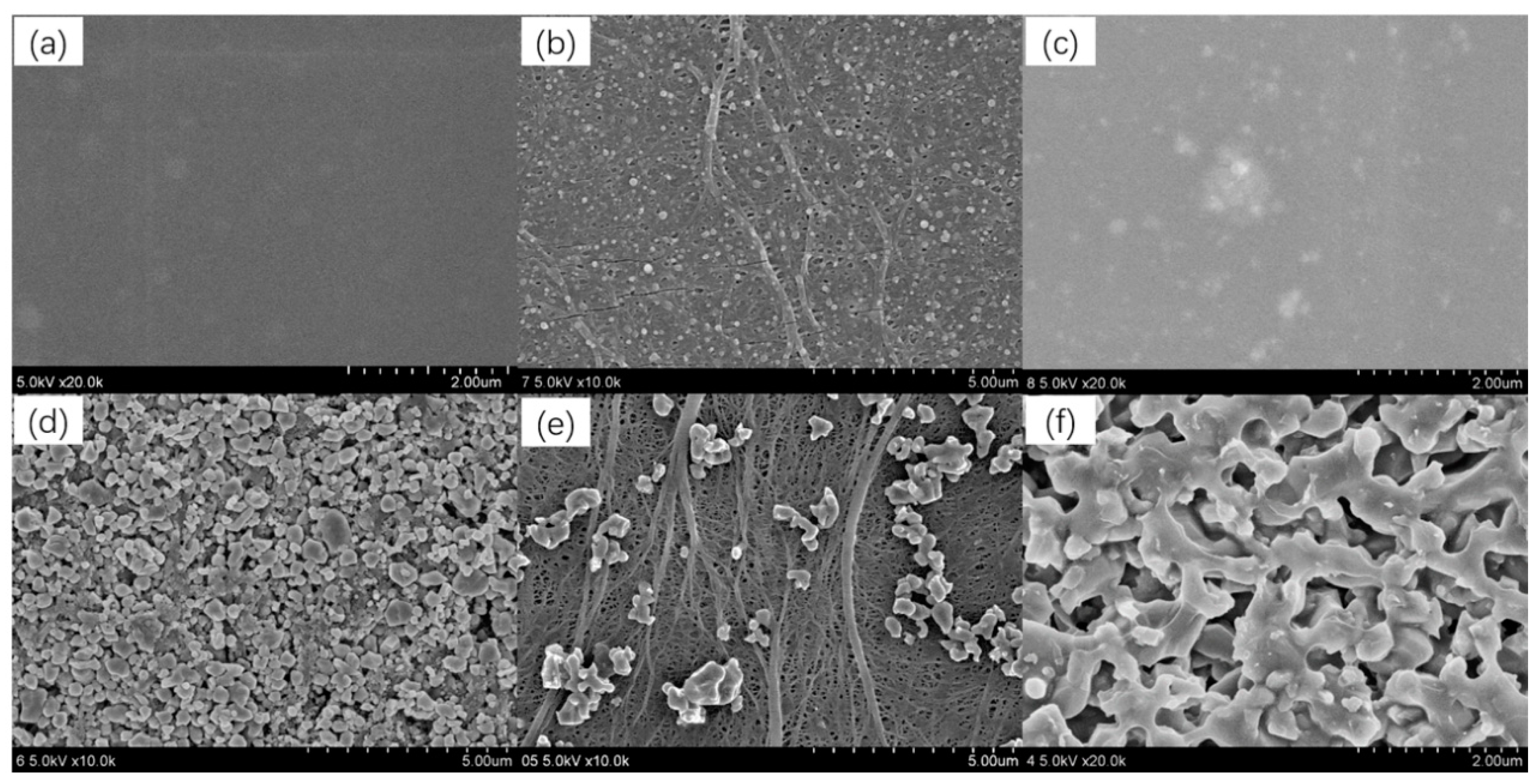
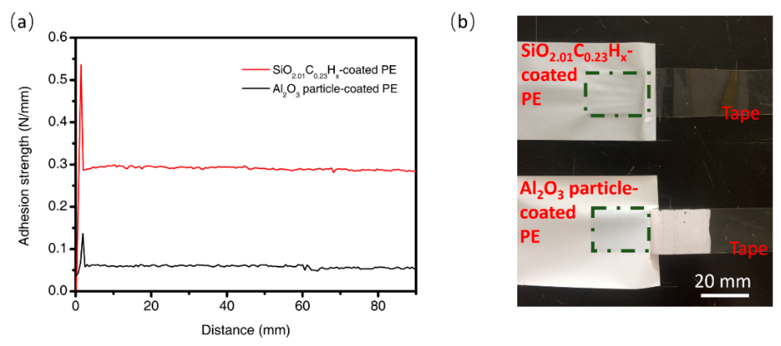
3.2. Adhesion Characteristics of the Coatings

The coating adhesion strength is closely related with the coating structure and composition. As analyzed from SEM, FTIR, and XPS, the coating is a layer of nanoparticulate film on top of and deep inside the PE separator. It is composed of inorganic components like SiO2, SiO, and Si–OH, and organic components like C–O, C–C, or C=O, as well as hybrid components like Si–C, which connects the nanoparticulate layer closely to the PE separator and helps improve the adhesion performance of the coating with the organic separator. As displayed and discussion in Section 3.1 above, the hybrid SiO2.01C0.23Hx nanoparticulate coating is distributed across the porous separator cross-section in a gradient, which is benefit for improving the coating with the organic separator. Figure 4a shows that the bare tape does not have any discernible surface roughness. Figure 4d shows that micro Al2O3 particles cover the separator densely, and no fiber network can be observed. The surface of the residual separators and the tapes after the peel-off test is shown in Figure 4b–f, respectively. Many uniformly distributed nanoparticles can still be clearly observed on the plasma-coated PE in Figure 4b. The SEM images of the tape surface removed from the plasma-coated PE shows few nanoparticles (Figure 4c). Because the striped nanoparticles had been affected by the surrounding glue, no sharp boundary of the particles can be clearly observed. These results indicate that the nanoparticulate layer was tightly bound to the PE surface. However, it can be seen in Figure 4e that most of the PE fiber network was exposed and only a few Al2O3 particles remained on the PE separator after the peeling processing. The Al2O3 particle layer was almost completely removed and stuck onto the tape (Figure 4f).
As shown in Figure 5a, the SiO2.01C0.23Hx-nanoparticulate coated PE shows greatly improved adhesion strength (0.28 N/mm) compared with that of the Al2O3 particle-coated PE (0.06 N/mm). The optical photo (Figure 5b) clearly shows that the tape peeling off from the plasma-coated PE remained transparent, whereas the tape from the Al2O3 particle-coated PE became white with the Al2O3 particle layer visible to the naked eye. Weighing the PE samples before and after peeling showed that the Al2O3 particle-coated PE had a 12.58% weight loss, while the SiO2.01C0.23Hx-nanoparticulate-coated PE had almost zero weight loss. This indicates that SiO2.01C0.23Hx-nanoparticulate coating adheres to PE surface firmly; however, the adhesion measurement needs to improve because the application situation will not be the same as during a test.

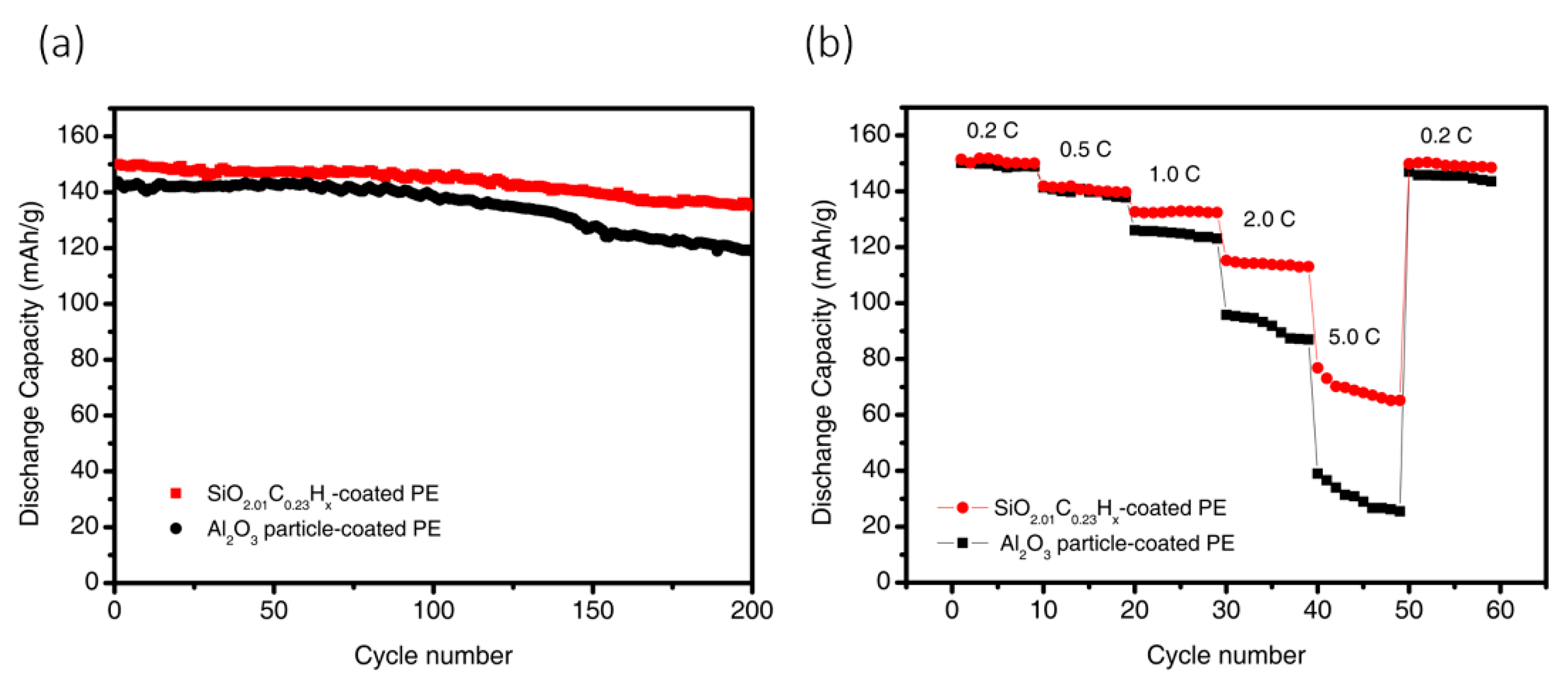
3.3. Electrochemical Performance

The cycling performances of cells assembled with the Al2O3 particle-coated PE or SiO2.01C0.23Hx-coated PE was evaluated with a voltages ranged from 2.5 to 4.2 V at 0.5 C. As shown in Figure 6a, for the first cycle, the SiO2.01C0.23Hx-nanoparticulate-coated PE separator showed a discharge capacity of 150.1 mA·h·g−1 and a coulombic efficiency of 99.8%. In contrast, the Al2O3 particle-coated PE separator had a discharge capacity of 147.3 mA·h·g−1 and a coulombic efficiency of 99.6%. After 200 cycles, the SiO2.01C0.23Hx-nanoparticulate-coated PE separator maintained 89.94% of its initial discharge capacity, which is higher than the Al2O3 particle-coated PE separator, which maintained 83.1%.
We evaluated the C-rate performance of the cells at discharge rates ranging from 0.2 to 5 C. As shown in Figure 6b, when the discharge rate is less than 1 C, the difference in the discharge capacity retention is negligible. This difference becomes obvious at 1 C. At a discharge rate of 5 C, the cell with the SiO2.01C0.23Hx-nanoparticulate-coated PE separator retained 45.6% of the initial discharge capacity of 0.1 C, while the Al2O3 particle-coated PE separator retained only 20.6%. The deposition of the hybrid structure causes the coatings stick to the separator more tightly. Meanwhile, the reactive groups provide more ion channels during the charge and discharge process. It provides similar or even better electrochemical performance than that using atmospheric graft plasma or oxidization plasma.

4. Conclusions

With focus on enhancing the adhesion between the PE separator and nanoparticulate coating, AP-PECVD was successfully used to deposit a hybrid SiO2.01C0.23Hx nanoparticulate layer on the top surface of and deep inside the PE separator. The atomic ratio of O/C and Si/C decreases from the top surface to the middle of the separator in a gradient. This nanoparticulate layer is composed of inorganic components like SiO2, SiO, and Si–OH, and organic components like C–O, C–C, or C=O, as well as hybrid components like Si–C. This hybrid coating connects the nanoparticulate layer closely with PE separator and helps to improve the adhesion performance of the coating with the organic separator. The average adhesion strength of a plasma-coated separator is 0.28 N/mm, which is much higher than that of commercial Al2O3 particle-coated separators (0.06 N/mm). Moreover, the cell with the SiO2.01C0.23Hx-coated separator delivered better electrochemical performance in C-rate and long-term cycle tests than that with a Al2O3 particle-coated separator. In consequence, this simple but effective method could be proposed as a potential alternative to the conventional inorganic particle coating process.

Author Contributions

Conceptualization, J.Z. and C.W.; Methodology, J.Z.; Software, Y.J.; Validation, Y.J.; Formal Analysis, Y.J., C.W., S.Q., and M.W.; Investigation, Y.J., N.Y., K.D., S.Q., Y.X., J.S., C.D., and M.W.; Resources, J.Z. and Z.W.; Data Curation, Y.J.; Writing—Original Draft Preparation, Y.J.; Writing—Review and Editing, Y.J., C.W., and J.Z.; Visualization, Y.J.; Supervision, J.Z.; Project Administration, J.Z.; Funding Acquisition, J.Z.

Funding

This research was financially supported by the Fundamental Research Funds for the Central Universities and the Nature Science Foundation of China (Nos. 10835004, 11375042, 11475043 and 11875104).

Acknowledgments

We are grateful to Shanghai Energy New Materials Technology Co., Ltd. who provided the PE separator and Analysis and Testing Center of Donghua University who offered comprehensive materials testing services.

Conflicts of Interest

The authors declare no conflict of interest.

References

  1. Liu, M.-H.; Zhang, P.-P.; Gou, L.; Hou, Z.; Huang, B. Enhancement on the thermostability and wettability of lithium-ion batteries separator via surface chemical modification. Mater. Lett. 2017, 208, 98–101. [Google Scholar] [CrossRef]
  2. Cui, Z.Y.; Shi, H.B.; Ding, J.Y.; Zhang, J.; Wang, H.; Wang, H. Fabrication of poly (vinylidene fluoride) separator with better thermostability and electrochemical performance for lithium ion battery by blending polyester. Mater. Lett. 2018, 228, 466–469. [Google Scholar] [CrossRef]
  3. Chawla, N.; Bharti, N.; Singh, S. Recent advances in non-flammable electrolytes for safer lithium-ion batteries. Batteries 2019, 5, 19. [Google Scholar] [CrossRef]
  4. Zhang, K.; Xiao, W.; Liu, J.; Yan, C. A novel self-binding composite separator based on poly(tetrafluoroethylene) coating for Li-ion batteries. Polymers 2018, 10, 1409. [Google Scholar] [CrossRef]
  5. Zhao, J.; Hu, Q.; Wang, J.; Zhang, P.; Zhu, Y.; Wu, G.; Lv, Y.; Lv, L.; Zhao, Y.; Yang, M. Effects of island-coated PVdF-HFP composite separator on the performance of commercial lithium-ion batteries. Coatings 2018, 8, 437. [Google Scholar] [CrossRef]
  6. Shi, C.; Dai, J.; Li, C.; Shen, X.; Peng, L.; Zhang, P.; Wu, D.; Sun, D.; Zhao, J. A modified ceramic-coating separator with high-temperature stability for lithium-ion battery. Polymers 2017, 9, 159. [Google Scholar] [CrossRef]
  7. Lee, H.W.; Muralidharan, P.; Ruffo, R.; Mari, C.M.; Cui, Y.; Kim, D.K. Ultrathin spinel LiMn2O4 nanowires as high power cathode materials for Li-ion batteries. Nano Lett. 2010, 10, 3852. [Google Scholar] [CrossRef]
  8. Wang, G.; Liu, H.; Liu, J.; Qiao, S.; Lu, G.M.; Munroe, P.; Ahn, H. Mesoporous LiFePO4/C nanocomposite cathode materials for high power lithium ion batteries with superior performance. Adv. Mater. 2010, 22, 4944. [Google Scholar] [CrossRef]
  9. Kritzer, P.; Döring, H.; Emermacher, B. Improved safety for automotive lithium batteries: An innovative approach to include an emergency cooling element. Adv. Chem. Eng. Sci. 2014, 4, 197–207. [Google Scholar] [CrossRef]
  10. Zhu, W.; Huang, X.; Liu, T.; Xie, Z.; Wang, Y.; Tian, K.; Bu, L.; Wang, H.; Gao, L.; Zhao, J. Ultrathin Al2O3 coating on LiNi0.8Co0.1Mn0.1O2 cathode material for enhanced cycleability at extended voltage ranges. Coatings 2019, 9, 92. [Google Scholar] [CrossRef]
  11. Lee, H.; Yanilmaz, M.; Toprakci, O.; Fu, K.; Zhang, X. A review of recent developments in membrane separators for rechargeable lithium-ion batteries. Energy Environ. Sci. 2014, 7, 3857. [Google Scholar] [CrossRef]
  12. Linden, D.; Reddy, T.B. Handbook of Batteries; McGraw-Hill: New York, NY, USA, 2002. [Google Scholar]
  13. Arora, P.; Zhang, Z. Battery separators. Chem. Rev. 2004, 104, 4419–4462. [Google Scholar] [CrossRef] [PubMed]
  14. Zhang, S.S. A review on the separators of liquid electrolyte Li-ion batteries. J. Power Sources 2007, 164, 351–364. [Google Scholar] [CrossRef]
  15. Tobishima, S.-I.; Yamaki, J.-I. A consideration of lithium cell safety. J. Power Sources 1999, 81, 882–886. [Google Scholar] [CrossRef]
  16. Lee, H.; Jeon, H.; Gong, S.; Ryou, M.-H.; Yong, M.-L. A facile method to enhance the uniformity and adhesion properties of water-based ceramic coating layers on hydrophobic polyethylene separators. Appl. Surf. Sci. 2018, 427, 139–146. [Google Scholar] [CrossRef]
  17. Cai, M.; Zhu, J.; Yang, C.; Gao, R.; Shi, C.; Zhao, J. A parallel bicomponent TPU/PI membrane with mechanical strength enhanced isotropic interfaces used as polymer electrolyte for lithium-ion battery. Polymers 2019, 11, 185. [Google Scholar] [CrossRef]
  18. Liu, J.C.; Yang, K.; Mo, Y.D.; Wang, S.J.; Han, D.M.; Xiao, M.; Meng, Y.Z. Highly safe lithium-ion batteries: High strength separator from polyformaldehyde/cellulose nanofibers blend. J. Power Sources 2018, 400, 502–510. [Google Scholar] [CrossRef]
  19. Starostin, S.A.; Premkumar, P.A.; Creatore, M.; de Vries, H.; Paffen, R.M.J.; van de Sanden, M.C.M. High current diffuse dielectric barrier discharge in atmospheric pressure air for the deposition of thin silica-like films. Appl. Phys. Lett. 2010, 96, 061502. [Google Scholar] [CrossRef] [Green Version]
  20. Alf, M.E.; Asatekin, A.; Barr, M.C.; Baxamusa, S.H.; Chelawat, H.; Ozaydin-Ince, G.; Petruczok, C.D.; Sreenivasan, R.; Tenhaeff, W.E.; Trujillo, N.J.; et al. Chemical vapor deposition of conformal, functional, and responsive polymer films. Adv. Mater. 2010, 22, 1993–2027. [Google Scholar] [CrossRef]
  21. Ma, D.; Li, Y.; Yang, J.; Mi, H.; Luo, S.; Deng, L.; Yan, C.; Zhang, P.; Lin, Z.; Ren, X.; et al. Robust SnO2−x nanoparticle-impregnated carbon nanofibers with outstanding electrochemical performance for advanced sodium-ion batteries. Nano Energy 2018, 43, 317. [Google Scholar] [CrossRef]
  22. Gawlik, G.; Ciepielewski, P.; Baranowski, J.M. Study of implantation defects in CVD graphene by optical and electrical methods. Appl. Sci. 2019, 9, 544. [Google Scholar] [CrossRef]
  23. Hu, Z.; Zheng, D.; Tu, R.; Yang, M.; Li, Q.; Han, M.; Zhang, S.; Zhang, L.; Goto, T. Structural controlling of highly-oriented polycrystal 3C-SiC bulks via halide CVD. Materials 2019, 12, 390. [Google Scholar] [CrossRef] [PubMed]
  24. Jäger, E.; Schmidt, J.; Pfuch, A.; Spang, S.; Beie, O.; Jäger, N.; Jantschner, O.; Daniel, R.; Mitterer, C. Antibacterial silicon oxide thin films doped with zinc and copper grown by atmospheric pressure plasma chemical vapor deposition. Nanomaterials 2019, 9, 255. [Google Scholar] [CrossRef] [PubMed]
  25. Sun, C.; Min, J.; Lin, J.; Wan, H. Effect of atmospheric pressure plasma treatment on adhesive bonding of carbon fiber reinforced polymer. Polymers 2019, 11, 139. [Google Scholar] [CrossRef]
  26. Zhang, J.; Di, L.; Yu, F.; Duan, D.; Zhang, X. Atmospheric-pressure cold plasma activating Au/P25 for CO oxidation: effect of working gas. Nanomaterials 2018, 8, 742. [Google Scholar] [CrossRef] [PubMed]
  27. Dudina, D.V.; Bokhonov, B.B.; Olevsky, E.A. Fabrication of porous materials by spark plasma sintering: A review. Materials 2019, 12, 541. [Google Scholar] [CrossRef]
  28. Kaushik, N.K.; Kaushik, N.; Linh, N.N.; Ghimire, B.; Pengkit, A.; Sornsakdanuphap, J.; Lee, S.-J.; Choi, E.H. Plasma and nanomaterials: fabrication and biomedical applications. Nanomaterials 2019, 9, 98. [Google Scholar] [CrossRef] [PubMed]
  29. Qin, S.; Wang, M.; Wang, C.; Jin, Y.; Yuan, N.; Wu, Z.; Zhang, J. Binder-free nanoparticulate coating of a polyethylene separator via a reactive atmospheric pressure plasma for lithium-ion batteries with improved performances. Adv. Mater. Interfaces 2018, 5, 1800579. [Google Scholar] [CrossRef]
  30. Wang, D.; Yang, Q.; Guo, Y.; Liu, X.; Shi, J.; Zhang, J. One step growth of TiO2 crystal trees by atmospheric pressure plasma jet. Mater. Lett. 2011, 65, 2526–2529. [Google Scholar] [CrossRef]
  31. Jeon, H.; Jin, S.; Park, W.; Lee, H.; Kim, H.; Ryou, M.; Lee, Y. Plasma-assisted water-based Al2O3 ceramic coating for polyethylene-based microporous separators for lithium metalsecondary batteries. Electrochim. Acta 2016, 212, 649–656. [Google Scholar] [CrossRef]
  32. Wang, Z.; Zhu, H.; Yang, L.; Wang, X.; Liu, Z.; Chen, Q. Plasma modified polypropylene membranes as the lithium-ion battery separators. Plasma Sci. Technol. 2016, 18, 424. [Google Scholar] [CrossRef]
Figure 1. (a) Scanning electron microscopy (SEM) and high magnification (inset) images of bare polyethylene (PE); (b) SEM and high magnification (inset) images of the nanoparticulate-coated PE separator; (c) size range of the nanoparticulate on PE surface in (b).
Coatings 09 00190 g001
Figure 2. (a) Attenuated total reflection Fourier transform infrared spectroscopy (ATR-FTIR) spectra before and after plasma coating; (b) x-ray photoelectron spectroscopy (XPS) spectrum for the SiOxCyHz nanoparticulate film; (c) C 1s spectra; (d) Si 2p spectra.
Coatings 09 00190 g002
Figure 3. (a) Cross-section SEM image of SiO2.01C0.23Hx-coated PE separator; (b,c) are corresponding energy dispersive X-ray spectroscopy (EDS) maps of the Si and O, respectively; (d) cross-section SEM image of Al2O3 particle-coated PE separator; (e,f) are corresponding EDS maps of the Al and O, respectively.
Coatings 09 00190 g003
Figure 4. SEM images of (a) bare tape; (b) the SiO2.01C0.23Hx-coated PE separator after peel-off test; (c) corresponding tape surface to (b); (d) the Al2O3 particle-coated PE separator; (e) the Al2O3 particle-coated PE separator after peel-off test; (f) corresponding tape surface to (e).
Coatings 09 00190 g004
Figure 5. (a) Adhesion strengths of different coating samples; (b) the optical photo of the separators and tapes after the 180° peel-off test.
Coatings 09 00190 g005
Figure 6. (a) The cycling performance; (b) C-rate capacity.
Coatings 09 00190 g006

