Article

Corrosion Resistant TiTaN and TiTaAlN Thin Films Grown by Hybrid HiPIMS/DCMS Using Synchronized Pulsed Substrate Bias with No External Substrate Heating

1
Lib. Norponiente 2000, Fracc. Real de Juriquilla, CINVESTAV-Unidad Queretaro, Queretaro 76230, Mexico
2
Department of Physics (IFM), Linköping University, SE 581 83 Linköping, Sweden
3
Department of Mechanical and Mechatronic Engineering, Faculty of Engineering, Universidad Nacional de Colombia, Bogota 14490, Colombia
4
Department of Material Science, Physics, and the Frederick Seitz Materials Research Laboratory, University of Illinois, Urbana, IL 61801, USA
5
Department of Science, CIDETEQ, Queretaro, Qro 76703, Mexico
6
Department of Physics, University of Illinois, Urbana, IL 61801, USA
7
Materials Science Department, National Taiwan University of Science and Technology, Taipei 10607, Taiwan
*
Author to whom correspondence should be addressed.
Coatings 2019, 9(12), 841; https://doi.org/10.3390/coatings9120841
Submission received: 12 November 2019 / Revised: 29 November 2019 / Accepted: 2 December 2019 / Published: 9 December 2019
(This article belongs to the Section Corrosion, Wear and Erosion)

Abstract

:
Ti0.92Ta0.08N and Ti0.41Al0.51Ta0.08N thin films grown on stainless-steel substrates, with no external heating, by hybrid high-power impulse and dc magnetron sputtering (HiPIMS/DCMS), were investigated for corrosion resistance. The Ta target was operated in HiPIMS mode to supply pulsed Ta-ion fluxes, while two Ti (or Ti and Al) targets were operated in DCSM mode in order to provide a high deposition rate. Corrosion resistance was investigated using potentiodynamic polarization and electrochemical impedance spectroscopy employing a 3.5% NaCl solution at room temperature. The 300-nm-thick transition-metal nitride coatings exhibited good corrosion resistance due to film densification resulting from pulsed heavy Ta-ion irradiation during film growth. Corrosion protective efficiencies were above 99.8% for both Ti0.41Al0.51Ta0.08N and Ti0.92Ta0.08N, and pore resistance was apparently four orders of magnitude higher than for bare 304 stainless-steel substrates.

1. Introduction

Refractory transition-metal (TM) nitride thin films are used in a wide variety of applications due to their unique combination of properties, which include high hardness [1,2,3,4,5]; scratch and abrasion resistance [6]; low coefficient of friction [7]; high-temperature oxidation resistance [8,9,10]; and tunable optical [11,12], electrical [11,13,14], and thermal [14], properties. As a result, TM nitrides are widely used as wear-resistant coatings [15,16], decorative coatings [17], and diffusion barriers [18,19,20,21,22,23,24]; the latter because of their high thermal stability [10,25] and low electrical resistivity [13].
For many of the above applications, especially diffusion barriers, dense, high-crystalline-quality films grown by physical vapor deposition (PVD) at much lower temperatures are required in order to minimize deposition cycling times and allow the use of thermally-sensitive substrates such as polymers and light-weight metals (e.g., Li, Mg, and Al). The primary technique employed to obtain dense, hard, low-stress refractory thin films by PVD at reduced growth temperatures has been the use of inert-gas ion irradiation [26,27,28,29] to provide dynamic ion mixing and ion-bombardment-enhanced surface adatom mobilities [26,29,30,31]. However, progress achieved in low-temperature densification by this route often comes at the expense of producing large compressive stresses due to trapping of inert gas ions, and recoil implantation of film atoms, into interstitial sites [26,29,30,31,32,33,34,35,36,37,38,39].
Greczynski et al. recently reported a novel PVD approach for the growth of dense, hard, and low-stress refractory TM nitride thin films without external substrate heating. [40] TiN was used as an initial model materials system, while employing hybrid high-power impulse and dc magnetron co-sputtering (HiPIMS/DCMS) [40,41,42], with synchronized substrate bias [40,41,42,43], to deposit Ti1−xTaxN [40] and Ti1−x−yAlyTaxN alloys [44]. Dense Ti0.92Ta0.08N and Ti0.41Al0.51Ta0.08N alloy films, with thicknesses between 2.0 and 2.6 μm, were grown with no external substrate heating. The Ta concentration of 8 at % on the cation sublattice was chosen based upon the desire to minimize plasma heating of the substrate during HiPIMS pulses at the Ta target, while still delivering a sufficient flux of energetic heavy Ta+/Ta2+ ions to provide film densification via overlapping collision cascades as discussed in detail in ref. [40]. Maximum film deposition temperatures Ts due to plasma heating were <120 °C.
Here, we investigate the corrosion resistance, in saline environments, of Ti0.92Ta0.08N and Ti0.41Al0.51Ta0.08N alloys deposited by hybrid HiPIMS/DCMS co-sputtering, with synchronized substrate bias [40,44], on polished 304 stainless-steel substrates. Corrosion tests were performed in a conventional electrochemical cell, employing a saturated calomel electrode (SCE) as a reference, with a 3.5% NaCl solution at room temperature. Potential scans were conducted from −0.3 to +0.4 V after each sample was immersed in the solution for 45 min; corrosion potentials, corrosion current densities, anodic slopes, and cathodic slopes were determined. Electrochemical impedance spectroscopy (EIS) measurements were performed at open-circuit potential using the same cell configuration and sample area as in the polarization experiments. The overall results for the 300-nm-thick hybrid DCMS/HiPIMS TiTaN and TiAlN layers show that both sets of films exhibit enhanced corrosion resistance in 3.5% NaCl solutions, with more noble corrosion potentials and lower corrosion currents, than much thicker (1.6 µm) TiN coatings deposited by HiPIMS [45], 1.25-µm-thick TiN coatings deposited by HiPIMS and DCMS [46], 5.3-µm-thick Ti/TiN multilayers deposited by electron-beam evaporation [47], and 2-µm-thick TiN/TiAlN multilayers deposited by DCMS [48].

2. Experimental Procedures

2.1. Film Growth

Ti0.92Ta0.08N and Ti0.41Al0.51Ta0.08N alloy fiIms were grown, based upon calibration curves for film compositions vs. target powers and substrate bias [40,44], in a CC800/9 CemeCon AG magnetron sputtering system equipped with cast rectangular 8.8 × 50 cm2 Ti, Al, and Ta targets. Stainless-steel 304 and Si(001) substrates, 2.54 × 1.00 and 2.00 × 1.00 cm2, respectively, were mounted directly below, and parallel to, the Ta target. Either two Ti targets, or a Ti and an Al target, were mounted symmetrically on each side of the Ta target and tilted toward the substrate with a 21° angle between the substrate normal and the normal to each outlying target. The target-to-substrate distance was 18 cm, and the system base pressure was 3.8 × 10⁻⁷ Torr (0.05 mPa). The substrates were cleaned sequentially in acetone and isopropyl alcohol before being mounted on a platen with clips.
No external substrate heating was applied during deposition and substrate temperature Ts, monitored with calibrated [40] thermocouples bonded to dummy substrates, reached a maximum of <120 °C, due to plasma heating, during deposition of 300-nm-thick films.
In the hybrid approached used magnetron with Ta target was driven in HiPIMS mode to provide Ta-ion irradiation, while the Ti and Al targets were operated in DCMS mode [40]. The average HiPIMS-Ta target power was 1.0 kW with a pulse energy of 5 J at a pulsing frequency of 100 Hz (2% duty cycle). The corresponding peak target current density JT during each HiPIMS pulse was 0.2 A/cm2. The power to each dc magnetron was 3 kW when operating with two Ti targets, and 6.0 and 4.3 kW, respectively, when operating with Ti and Al targets.
Substrate bias, Vs = 160 V, is applied in pulses of negative polarity synchronized with the 200 μs metal-ion-rich portion of each HiPIMS pulse [40]. Time-resolved mass and energy spectroscopy analyses performed at the substrate position revealed that the metal-rich phase starts at time t = 50 μs following pulse initiation (t = 0 μs) with Ta+ and Ta2+ metal-ion fluxes incident at the film growth surface. At all other times, the substrates are at negative floating potential, Vs = Vf = 12 V. The maximum densities of incident Ta+ and Ta2+ ions were 3.1 × 10⁶ and 4.3 × 10⁶ cps, and the fraction Ta2+/(Ta+ + Ta2+) of doubly-ionized Ta2+ metal-ion flux during HiPIMS pulses was 0.54. A more detailed description of the resulting Ta+/Ta2+ irradiation conditions was presented in reference [40].

2.2. Film Characterization

2.2.1. Film Compositions

The metal fractions x and y in Ti1−xTaxN and Ti1−x−yAlyTaxN film were obtained from energy-dispersive x-ray spectroscopy (EDS) measurements, carried out on fracture cross-sections of films grown on Si(001) wafers, in a LEO 1550 scanning electron microscope (SEM) (Carl Zeiss, Oberkochen, Germany) equipped with an AZtec X-max EDS system operated at 20 keV. N/metal fractions and background impurity concentrations were obtained by time-of-flight elastic recoil detection analyses (TOF-ERDA) employing a 36 MeV 127I8+ beam incident at 67.5° relative to the sample normal, with the detector at a 45° recoil scattering angle [49]. ERDA data were analyzed using the CONTES code [50]. The obtained N/metal ratios = 1.00 ± 0.05, reveal that all layers are stoichiometric. The uncertainties in the reported metal concentrations, Ti0.92Ta0.08N and Ti0.41Al0.51Ta0.08N, on the cation sublattice were less than ±1%. oxygen and argon concentrations were lower than 0.4 and 0.5 at %, respectively, while carbon was below the detection limit.

2.2.2. Film Microstructure

For the corrosion experiments, 300-nm-thick Ti0.92Ta0.08N and Ti0.41Al0.51Ta0.08N layers were deposited on polished 304 stainless-steel substrates. θ–2θ X-ray diffraction (XRD) and X-ray reflectivity (XRR) scans were acquired with a Philips X-Pert MRD system to determine film orientation and density. XRR results, analyzed using the fitting procedure described in ref. [51], are reported for Ti0.92Ta0.08N and Ti0.41Al0.51Ta0.08N layers in references [40] and [44], respectively. Film microstructure was analyzed using plan-view and cross-sectional scanning electron microscopy (XSEM), before and after corrosion testing, in a 7601F instrument (JEOL, Tokyo, Japan).

2.2.3. Electrochemical Measurements

Ti0.92Ta0.08N and Ti0.41Al0.51Ta0.08N layers, 300-nm-thick as determined by profilometry measurements, on polished 304 stainless-steel substrates were subjected to corrosion tests carried out in a conventional electrochemical cell employing a saturated calomel electrode (SCE) in room-temperature 3.5% NaCl solutions with a Gamry 600 potentiostat (Gamry Instruments, Warminster, PA, USA). The exposed sample area was always 0.17 cm2. In these investigations, the potential is scanned from −0.3 to +0.4 V vs. SCE, with a 0.4 mV s−1 potential sweep, following 45-min sample immersions in 3.5% saline solutions. The results were analyzed to determine the corrosion potential Ecorr, corrosion current density jcorr, anodic slope ba, and cathodic slope bc by means of the Tafel extrapolation method [52] using the Echem Analyst software (Version 5.30) [53] from Gamry Instruments.
Electrochemical impedance spectroscopy (EIS) measurements as a function of frequency were performed at open-circuit potential (OCP) with the same cell configuration, area, and potentiostat used in the polarization experiments. A 10-mV sinusoidal potential was applied at frequencies from 10−2 to 105 Hz and the results were acquired as a function of saline solution exposure times: 1, 24, 48, 72, and 168 h. Impedance plots were interpreted based upon an equivalent circuit analyzed using the Echem Analyst software version 5.30 [53].
X-ray photoelectron spectroscopy (XPS) composition depth profiles of Ti0.92Ta0.08N and Ti0.41Al0.51Ta0.08N layers on stainless-steel substrates, before and after corrosion testing, were obtained in an Axis Ultra DLD instrument (Manchester, UK) using monochromatic Al Kα radiation (hν = 1486.6 eV). The profiles were acquired as the samples were sputter-etched with a 4 keV, 12.7 mA cm−2, Ar+ beam incident at 70° with respect to the sample normal. Oxygen concentrations in bulk layers were below detection limits, ~1 at %, consistent with the films being essentially fully dense. In addition, there was no evidence for the presence of stainless-steel substrate species (primarily Fe, Cr, and Ni) in the films following the corrosion tests, again indicating that the layers were fully dense.

3. Results and Discussion

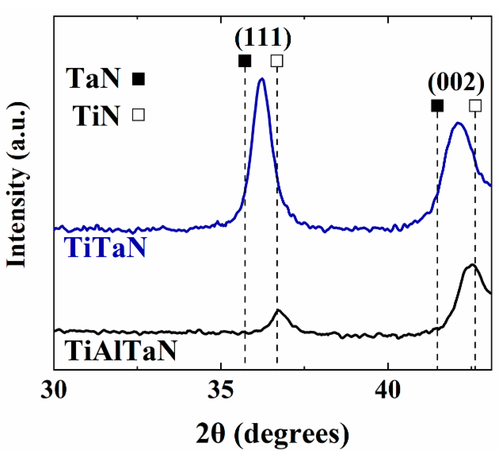
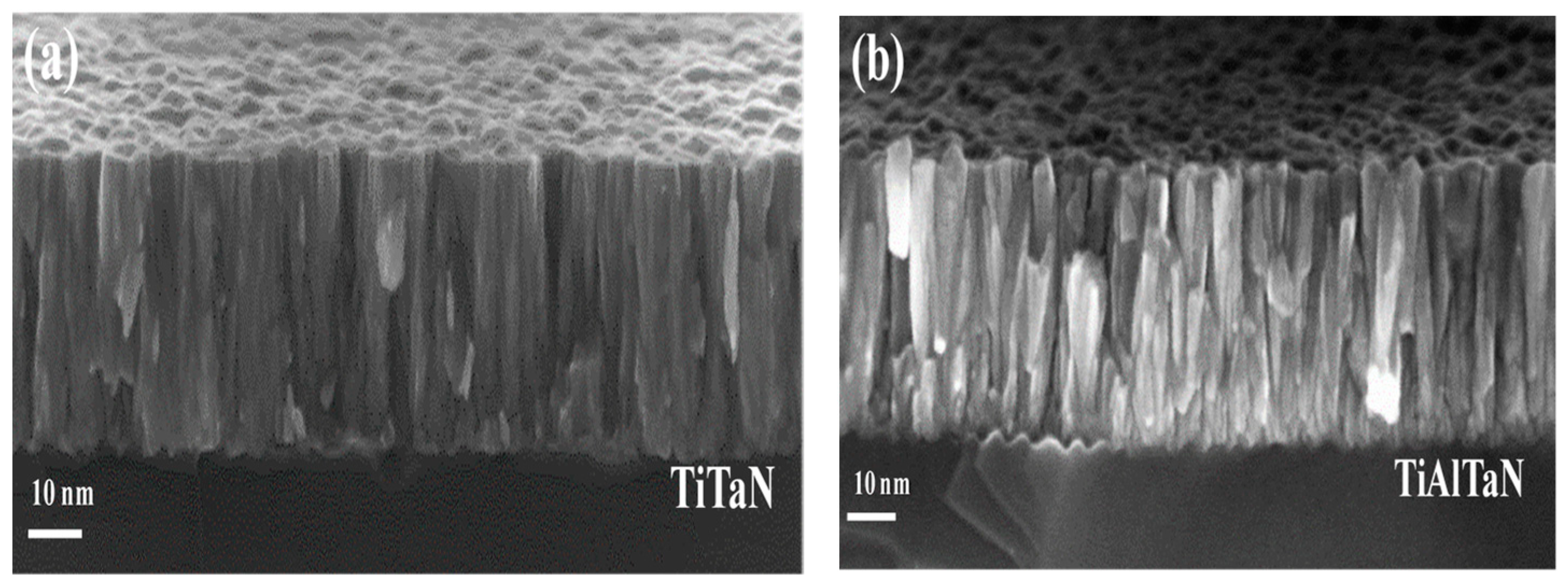
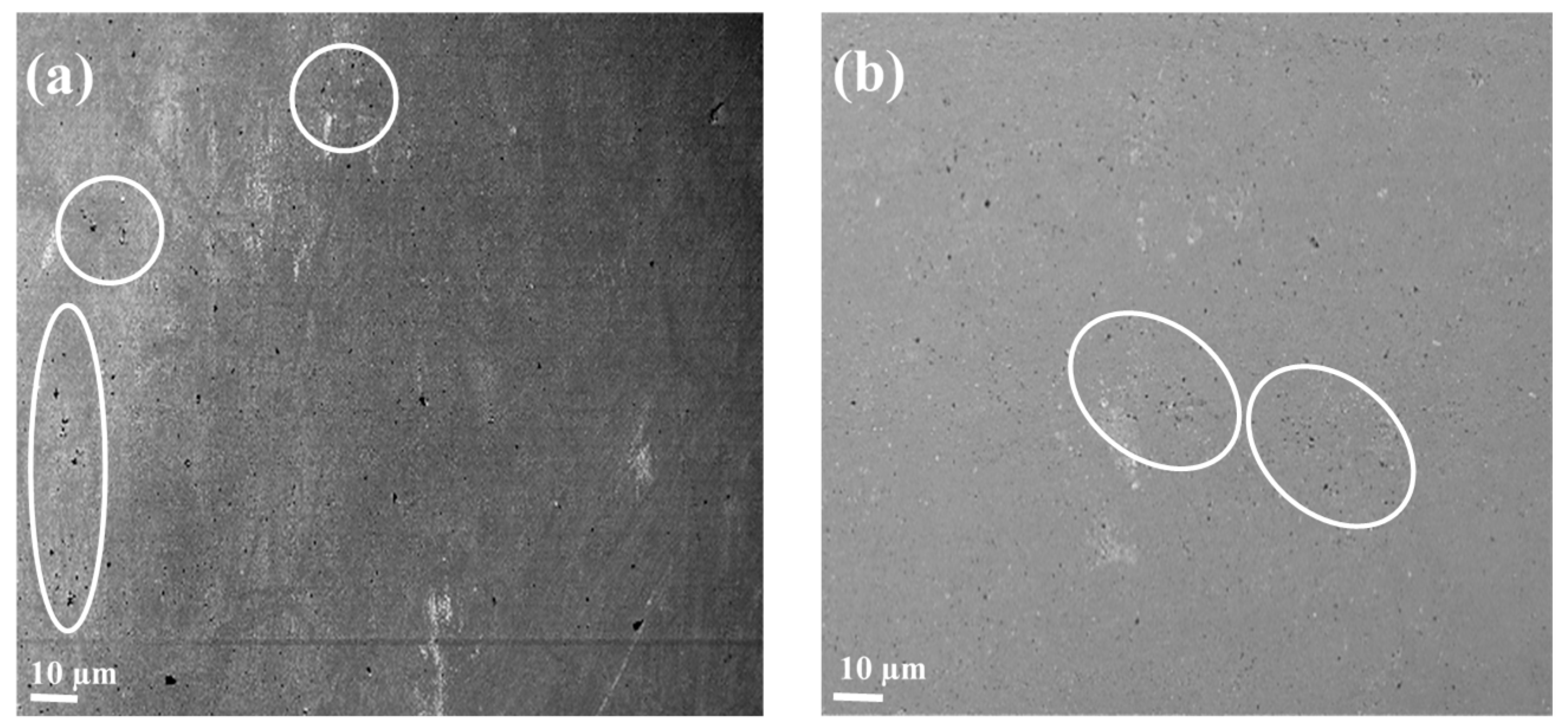
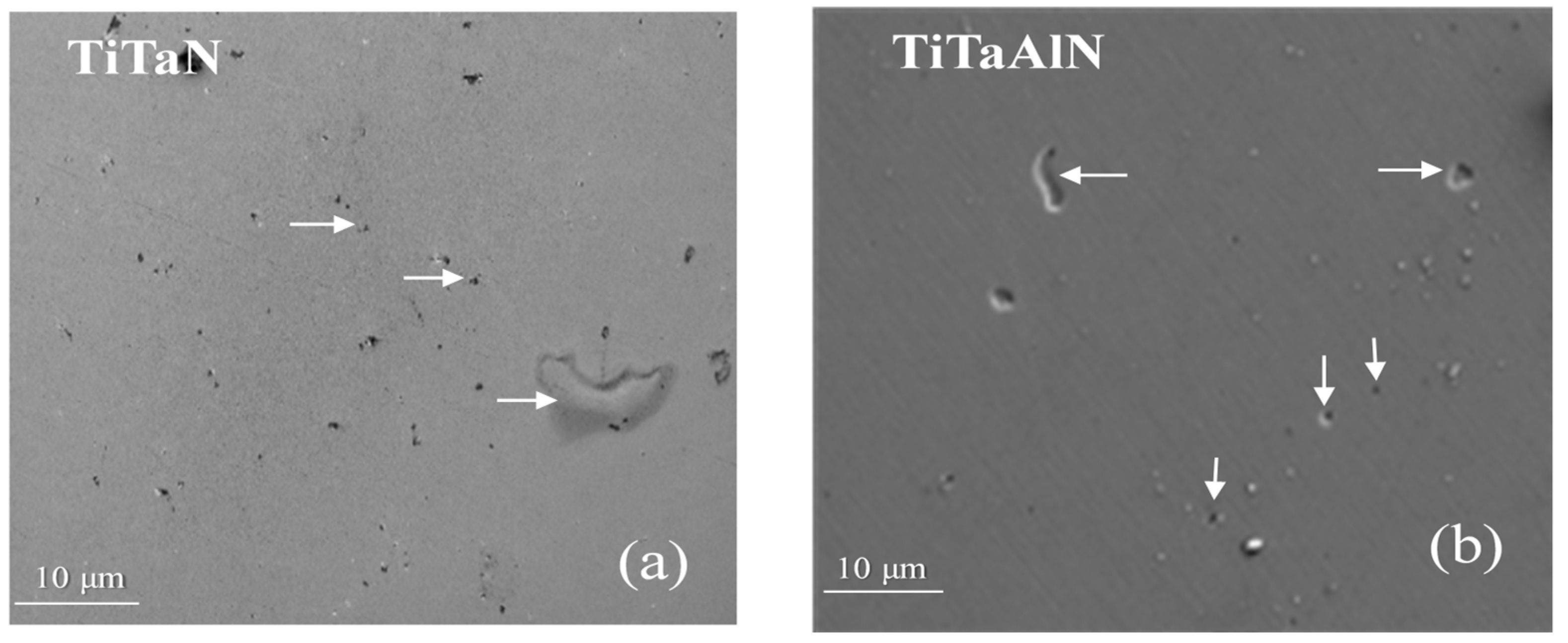
3.1. Film Microstructure

Ti0.92Ta0.08N and Ti0.41Al0.51Ta0.08N XRD scans are shown in Figure 1. The only observable features over the 2θ range from 10° to 43° are cubic B1-NaCl-structure (111) and (002) film peaks, small (022) film peaks, and the (111) and (002) peaks from the stainless-steel substrate. XRD peak positions and peak shapes for the TM nitride alloys are in agreement with previous XRD and selected-area electron diffraction (SAED) patterns obtained from Ti0.92Ta0.08N and Ti0.41Al0.51Ta0.08N layers described in [40,44].
The Ti0.92Ta0.08N 111 and 002 diffraction peaks in Figure 1 are shifted to lower 2θ values, with respect to TiN reference peaks, as a result of TaN alloying. TaN has a larger lattice constant, 4.35 Å, than that of TiN, 4.24 Å [40]. The relaxed lattice constant ao of Ti0.92Ta0.08N is 4.28 ± 0.01 Å as determined from XRD scans acquired at the strain-free tilt angle ψ, defined as ψ* = arcsin{2ν/(1 + ν)}, [40] in which ν is the Poisson ratio, 0.23 [40]. The residual compressive stress σ, obtained from sin2ψ analyses, is <1 GPa.
Ti0.41Al0.51Ta0.08N peak positions in Figure 1 are shifted to even larger 2θ values and the alloy has a relaxed lattice constant of 4.24 ± 0.01 Å. While XRD does not reveal any second-phase wurtzite-AlN peaks, SAED and lattice-resolution imaging [40] show the presence of small, nanometer-size (5 ± 3 nm) wurtzite-AlN grains at the boundaries between B1-NaCl-structure columns. The compressive stress in Ti0.41Al0.51Ta0.08N layers is 1.6 ± 0.2 GPa.
The combination of medium and high-resolution cross-sectional transmission electron microscopy (XTEM, FEI Tecnai G2 TF 20 UT) with corresponding selected-area electron diffraction (SAED) patterns, and XSEM analyses of thick Ti0.92Ta0.08N and Ti0.41Al0.51Ta0.08N samples grown on Si(001) substrates, shows that all films are columnar with a 111 preferred orientation and no observable porosity. The XTEM and SAED results are identical to those reported in [40,44] and are thus not repeated here. X-ray reflectivity data confirm that the films are essentially fully dense. For comparison, TiN films grown by DCMS under conditions (including the lack of external substrate heating) identical to those of the HiPIMS/DCMS alloy films, but without pulsed sputtering from the HiPIMS target, were extremely underdense (65% density) with inter- and intracolumnar voids [40]. XSEM results from films grown on 304 stainless-steel substrates show the same dense columnar structures as those grown on Si and XRD results confirm that the layers also exhibit 111 preferred orientation.
Figure 2 consists of typical Ti0.92Ta0.08N and Ti0.41Al0.51Ta0.08N XSEM images from 300-nm-thick layers grown on 304 stainless-steel substrates. Both films exhibit a dense, columnar, zone-T structure [36] with rounded column tops and smooth surfaces. Root-mean-square roughnesses, measured using a DEKTAK 150 profilometer, are 8.4 nm for Ti0.92Ta0.08N and 5.4 nm Ti0.41Al0.51Ta0.08N. The smoother Ti0.41Al0.51Ta0.08N surfaces correlates well with their smaller average grain sizes due to column renucleation and grain refinement resulting from a small degree of phase separation as indicated by XTEM. Average column diameters 〈d〉 are 68 ± 26 nm for Ti0.92Ta0.08N and 48 ± 14 nm for Ti0.41Al0.51Ta0.08N.

3.2. Electrochemical Behavior

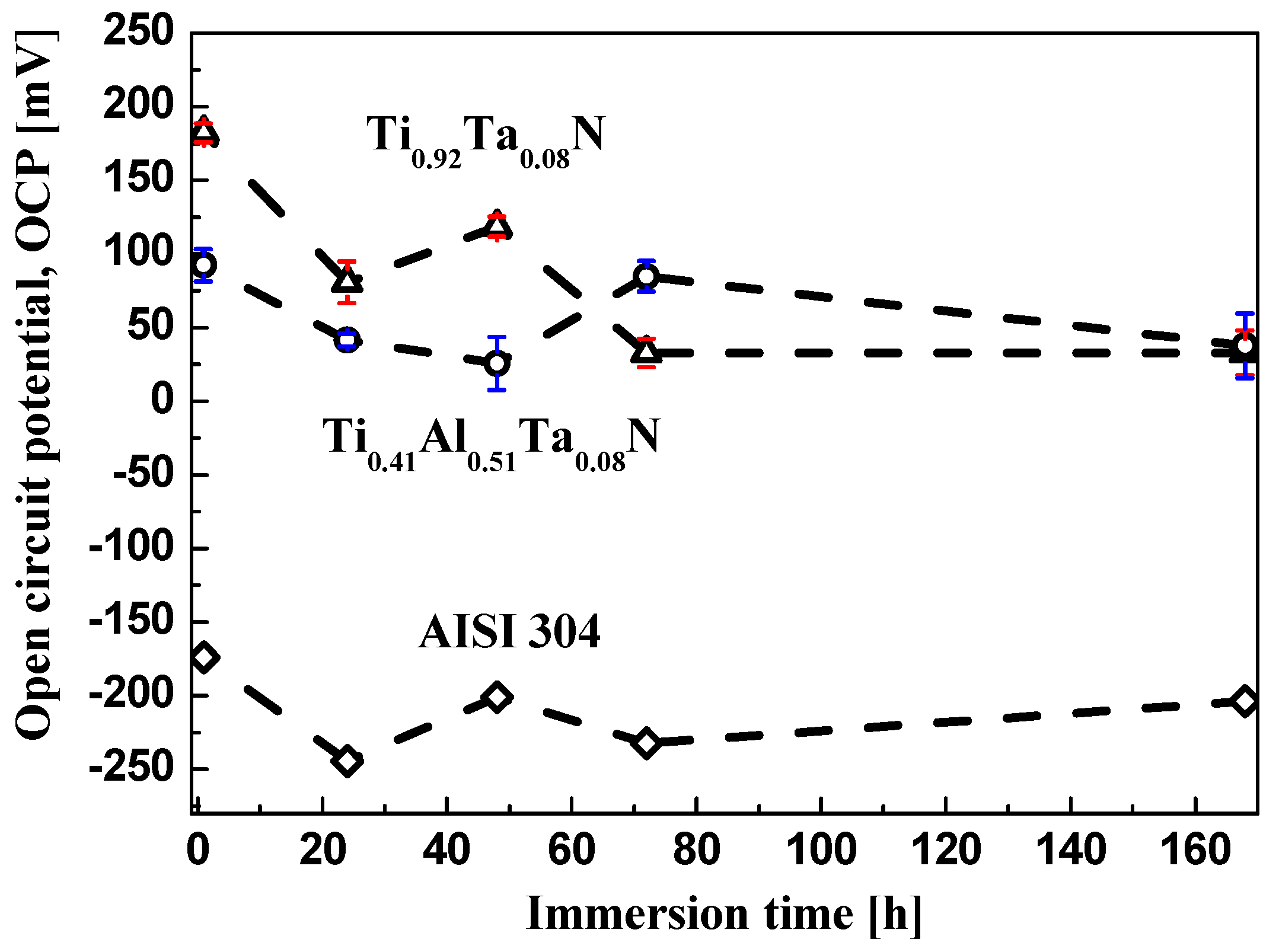
3.2.1. Potentiostatic Corrosion Measurements

The open-circuit potential (OCP) as a function of exposure time in room-temperature 3.5% brine solutions is shown in Figure 3 for Ti0.92Ta0.08N and Ti0.41Al0.51Ta0.08N thin films, as well as for an uncoated 304 stainless-steel substrate. Saturated calomel is used as the reference electrode. Local corrosion of the TM nitride and stainless-steel samples is promoted by Cl ions in the conducting electrolytic solution. The initial OCP measurements for each sample were made after 1 h of immersion in order to avoid transient effects [54]. Subsequent measurements were after 24, 48, 72, and 168 h of continuous immersion without external disturbance.
OCP values for uncoated substrate are negative for the entire 168 h of immersion, indicating, in agreement with potentiodynamic corrosion measurements presented in Section 3.2.2, a relatively low resistance to corrosion. It has been shown previously that 304 ss in 3.5% brine solutions forms a passive protective surface composed of a Cr-enriched inner oxide layer, with a hydroxide outer layer [55,56,57]. However, the oxide layer has a lower Cr concentration than in the fully passive state. Moreover, the CrOx layer is typically only a few nm thick and defective, such that the brine solution can induce pitting corrosion, resulting in a decrease in OCP. Over time, the CrOx layer forms and ruptures.
For 168 h of immersion, both Ti0.92Ta0.08N and Ti0.41Al0.51Ta0.08N exhibit a much more noble corrosion potential, with positive OCP values, than stainless steel, indicating a larger thermodynamic resistance to the onset of corrosion [58]. Thus, the TM nitride layers significantly enhance the corrosion resistance of their substrates.
The oscillations in the Ti0.92Ta0.08N OCP observed during the first 48 h of immersion are caused by brine in-diffusion through defective regions such as column boundaries. This decreases OCP and is followed by Ti and Ta oxide formation. With increasing immersion time, the defective oxide layer is permeated by the electrolyte, again causing decrease in OCP [55,56]. After 72 h of brine immersion the process saturates, since additional oxidation blocks further diffusion into the sample [59].
The OCP results for Ti0.41Al0.51Ta0.08N also exhibit oscillations, but on a longer time scale. There is an initial decrease in OCP during the first 48 h of immersion, which is due to electrolyte penetration through column boundaries. An aluminum-oxide layer that forms slowly leads to an increase in OCP, but since the oxide is defective, the OCP drops again, this time more slowly. Initial, Ti0.41Al0.51Ta0.08N OCP values are lower than those for Ti0.92Ta0.08N indicating an enhanced ion permeation rate into the layer, which is attributed to the smaller grain size (larger number density of column boundaries). The OCP is essentially the same for both TM nitride layers after 168 h of immersion in the brine solution.
The oscillations are very repeatable for both Ti0.92Ta0.08N and Ti0.41Al0.51Ta0.08N layers; an example of the agreement is shown in Figure 3 for Ti0.41Al0.51Ta0.08N.

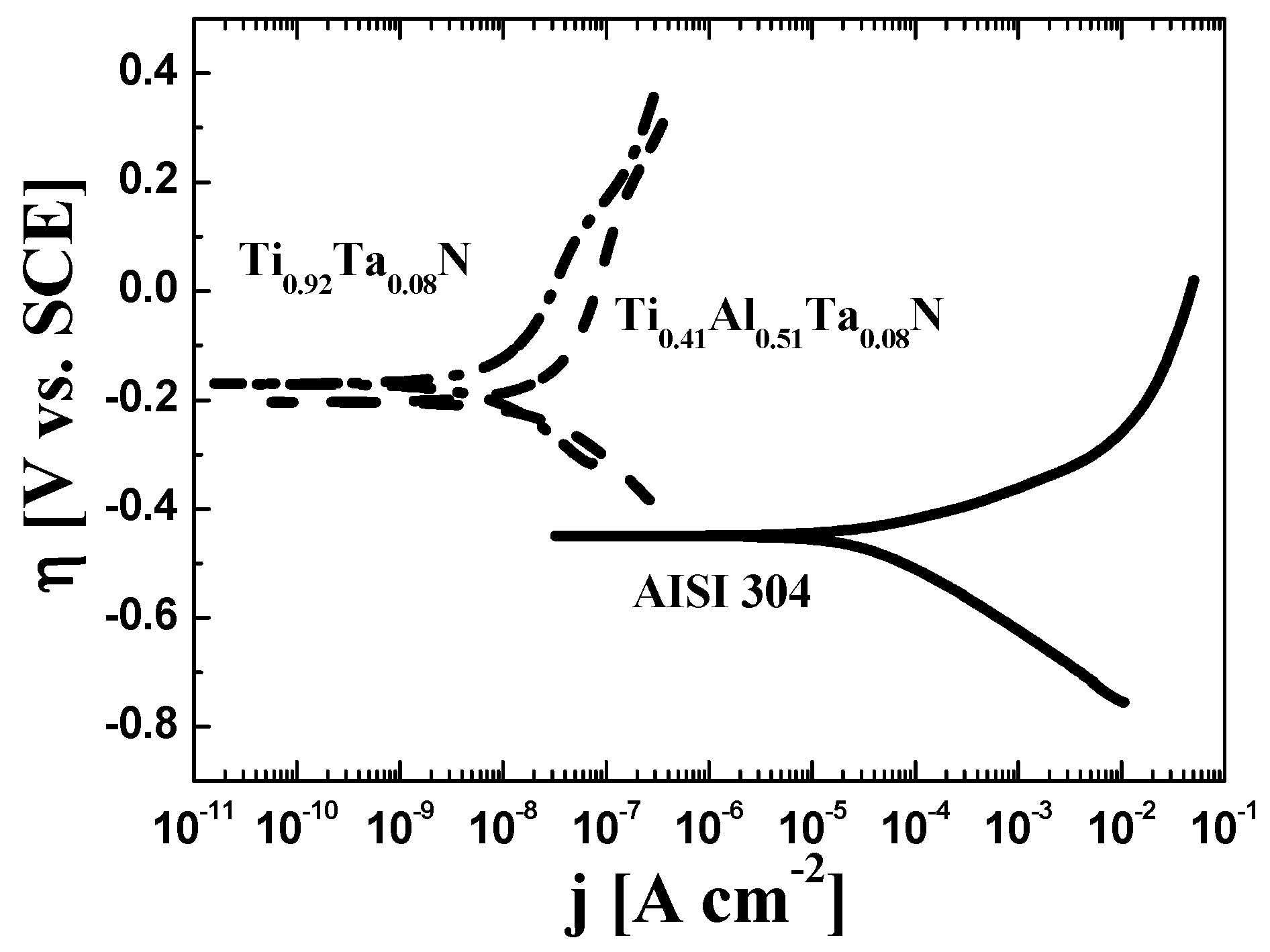
3.2.2. Potentiodynamic Corrosion Measurements

Figure 4 consists of potentiodynamic corrosion plots, recorded at RT after 45 min of sample immersion in 3.5% NaCl solution, for substrates coated with 300-nm-thick Ti0.92Ta0.08N and Ti0.41Al0.51Ta0.08N layers as well as for bare 304 stainless-steel substrates. The plots are based upon the Tafel equation [52]:
η = a + b   log ( j c o r r )
in which η is the electrochemical overpotential, η = (ηappliedηequilibrium), and jcorr is the net corrosion current density due to the application of the overpotential: that is, jcorr is the difference between the current density of the oxidation and reduction reactions, j c o r r   = j o x   | j r e d | . The term a in equation (1) is the exchange current density when η = 0, and b is the “Tafel slope” required to increase the equilibrium current density (η = 0) by an order of magnitude. The empirical parameters are obtained via the following equations:
a = 2.303 ( R T n F ) l o g ( j c o r r )
b = 2.303 ( R T n F )
for which n, R, and F are the number of electrons involved in the reaction, the ideal gas constant, and the Faraday constant, respectively. T is the system temperature; and α is the charge transfer coefficient, [53] defined as α c =   ( R T F ) ( d ln | I c | d E ) and α a =   ( R T F ) ( d ln | I a | d E ) for the cathodic and anodic reactions, respectively.
The applied overpotential η is plotted vs. the corrosion current density jcorr in the potentiodynamic curves in Figure 4. η is determined with respect to SCE, and the corrosion velocity is proportional to log(jcorr) [60]. The sequence of all parallel electrochemical reactions involved in the corrosion process is reflected in the plots. The upper branches show the anodic (oxidation) reactions resulting in film dissolution, followed by formation and breakdown of passive layers on 304 ss substrates. Correspondingly, the lower branches reveal the cathodic reactions which involve the reduction of hydrogen and oxygen. All these processes take place simultaneously, with the slower one determining the system corrosion velocity jcorr. Hence, the upper and lower branches intersection points in Figure 4 define the corrosion current density jcorr and the corrosion potential Ecorr. The latter parameter corresponds to the activation energy per atom necessary to dissolve the crystal lattice into the electrolyte. Corrosion proceeds more rapidly if Ecorr is negative with a small absolute value.
As shown in Figure 4, Ecorr for the 304 stainless-steel substrate is −0.450 V and jcorr is 3.60 × 10⁻⁵ A cm−2, while for substrates coated with Ti0.92Ta0.08N and Ti0.41Al0.51Ta0.08N layers, Ecorr is −0.170 and −0.204 V and jcorr is 1.88 × 10⁻⁸ and 5.40 × 10⁻⁸ A cm−2, respectively. The lower value of Ecorr and higher value of jcorr for bare stainless steel is due to the more rapid corrosion of stainless steel, which is accelerated in the presence of Cl ions that promote selective dissolution of iron [55,61]. In addition, the Cl ions can also breakdown the thin passive layer to cause pitting corrosion, giving rise to a decrease in OCP as shown in Figure 3 and discussed in Section 3.2.1.
Rp, the resistance of the system to leave its equilibrium state when an overpotential η is applied, was also evaluated. Rp is related to the corrosion rate jcorr through the anodic ba and cathodic bc Tafel slopes, determined using Equation (3), by the Stern-Geary equation [62,63]:
R p =   b a × b c 2.303 × j c o r r ( b a + b c )
As shown in Equation (4), there is an inverse relationship between Rp and jcorr; thus, at lower Rp, the corrosion current density is higher. To quantify the protection due to coating the 304 ss substrates, we calculate the protective efficiencies Pe correlating the corrosion current density of the film jcorr to that of the 304 ss substrate j c o r r ° via Equation (5) [47,48,64,65]:
( % ) P e =   [ 1 ( j c o r r j c o r r ° ) ] × 100
As summarized in Table 1, Rp for substrates coated with Ti0.41Al0.51Ta0.08N and Ti0.92Ta0.08N layers, increases roughly by four orders of magnitude, with respect to bare 304 ss. Table 1 also shows that the protective efficiency Pe is above 99.8% for both films: 99.84% for Ti0.41Al0.51Ta0.08N and 99.95% for Ti0.92Ta0.08N. We attribute the excellent corrosion resistance of Ti0.92Ta0.08N and Ti0.41Al0.51Ta0.08N layers, in protecting stainless-steel substrates, to microstructure densification caused by irradiation with heavy-metal Ta+/Ta2+ ions. This induces atomic mixing and decreases both inter- and intracolumn porosity [44] as shown in Figure 2.
Plan-view SEM images of the surface morphology of Ti0.92Ta0.08N and Ti0.41Al0.51Ta0.08N layers, following potentiodynamic polarization measurements, are shown in Figure 5. The films exhibit no evidence of local delamination or microcrack formation, only some minor surface defects are observed. For comparison, crack formation was reported for 1.4-µm-thick sputter-deposited Ti/TiN multilayer coatings deposited by rf sputtering on aluminum substrates after 72 h of immersion in brine [66]. The films exhibit no evidence of local delamination or microcrack formation, only some minor surface defects, small pits of average diameter 0.4–1.4 µm, are observed.

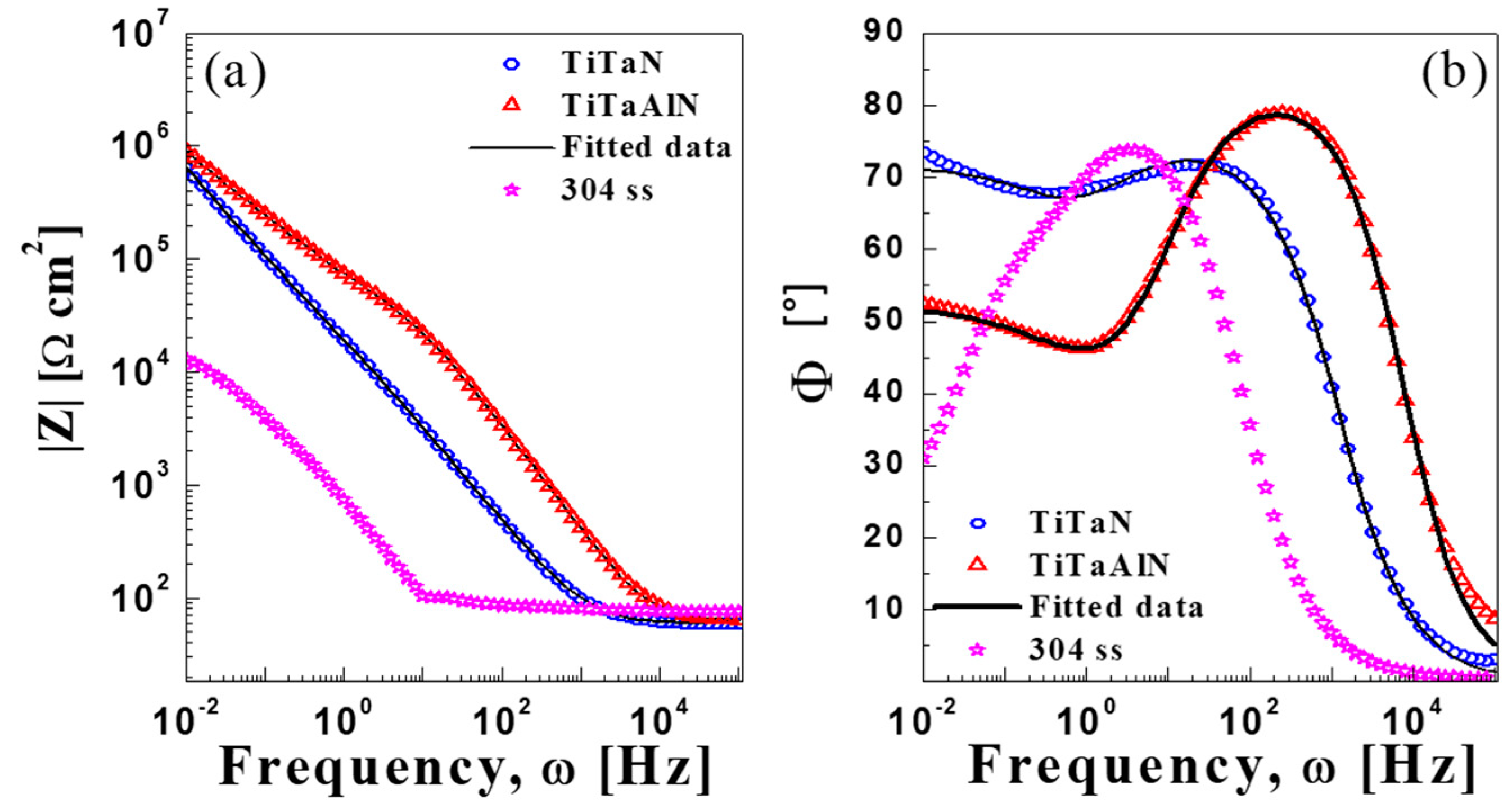
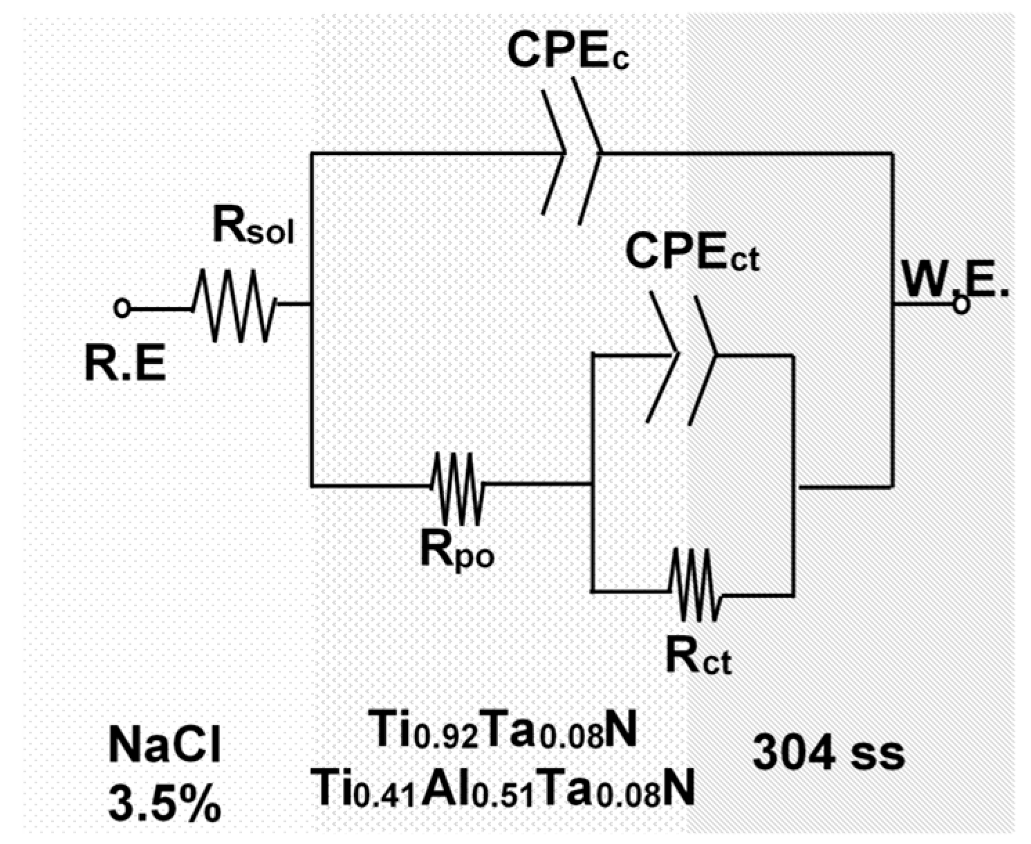
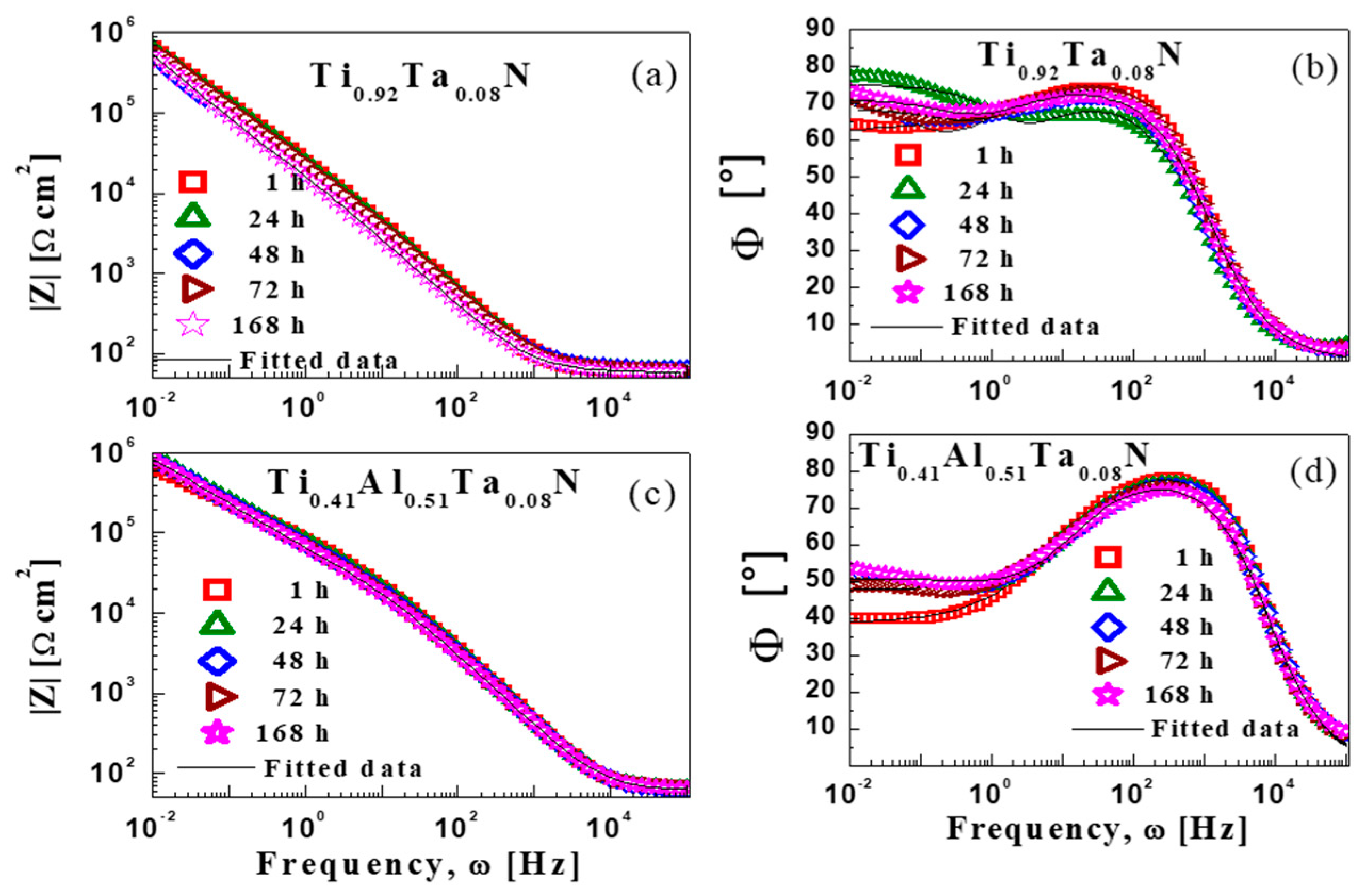
3.2.3. Impedance Measurements

The corrosion behavior of bare 304 stainless-steel substrates and substrates coated with 300-nm-thick Ti0.92Ta0.08N and Ti0.41Al0.51Ta0.08N layers was also investigated using electrochemical impedance spectroscopy (EIS). This technique was employed to determine the long-term performance of the coatings following immersion for 1, 24, 48, 72, and 168 h in 3.5% NaCl solution at room temperature. A small alternating-current signal, with minimal perturbation of the electrochemical system, was applied and the resulting current through the sample measured.
Figure 6 shows Bode plots for uncoated and Ti0.92Ta0.08N- and Ti0.41Al0.51Ta0.08N-coated 304 ss samples after 168 h of immersion in the electrolyte. The plots allow determination of the absolute system impedance |Z| as a function of frequency ω (Figure 6a), as well as the phase shift Φ between the sinusoidal current and voltage (Figure 6b). The latter results reveal the sample capacitive characteristics as a function of frequency. For impedance measurements at frequencies from 105 to 10−2 Hz, the current is distributed over the entire coated area and represents the response of the coating. At lower ω, from 100 to 10−2 Hz, the current is concentrated at sample pores [55,56]. After 168 h of immersion (ω = 100–10−2 Hz), the uncoated 304 stainless-steel sample has the lowest impedance |Z|, as shown in Figure 6a, while the Ti0.92Ta0.08N- and Ti0.41Al0.51Ta0.08N-coated samples have up to two orders of magnitude larger impedance.
At high frequencies, the peak in Φ vs. ω, Figure 6b, represents a strong capacitive response [55,56,67]. For bare 304 stainless-steel, the peak (Φ = 73.86°; 101 to 100 Hz) is due to the presence of a CrOx passive film which acts as a permeable protection barrier. The peaks for 304 ss coated with Ti0.92Ta0.08N (Φ = 71.80°; 102 to 101 Hz) and Ti0.41Al0.51Ta0.08N (Φ = 78.83; 103 to 102 Hz) layers correspond to the dielectric behavior of the coatings. After 168 h of immersion in saline solution, the capacitance of the Ti0.41Al0.51Ta0.08N film is higher than that of Ti0.92Ta0.08N. Over the frequency range from 10−1 to 10−2 Hz, the negative slope Φ vs. ω for the films indicates a change in the dielectric properties at the electrolyte/304-ss-substrate interface due to diffusion of the electrolyte through permeable coating defects including column boundaries.
To better understand the EIS results in Figure 6, the data are fit with an equivalent circuit (EC) model [55,68,69,70], which represents the transport of charge, with the equivalent amplitude and phase angle [54], during the electrochemical experiments. Values of the circuit components are a function of frequency ω. The EC, based on the model proposed by Kending et al. [71], is shown in Figure 7 and describes the electrochemical processes developed in our samples.
R.E. in Figure 7 is the saturated calomel reference electrode; the 304 ss substrates coated with Ti0.92Ta0.08N and Ti0.41Al0.51Ta0.08N are the working electrodes W.E. Rct represents the charge transfer and CPEct, in series with Rct, accounts for charge transfer via advection to the film/substrate interface through defects. Rpo is the resistance, in series with CPEc, to ion current through coating pores [56,71,72], and CPEc is the capacitance of the coating/electrolyte interface. The CPE impedance, Z C P E = Z 0 ( j ω ) m , varies with the power applied to the system via a power-law m, which is 0 for pure resistance and 1 for pure capacitance. If m > 0.8, CPE is considered capacitive [73].
Fits to EIS data were made with the Gamry Echem Analysis software (Version 5.30) [53] using the non-linear least squares method and the results are summarized in Table 2. For 304 stainless-steel, Rct and Rpo after 168 h of brine immersion are 1.1 × 10⁻¹ and 1.7 × 10² Ω·cm2, which are approximately nine and two orders of magnitude, respectively, lower than corresponding values for Ti0.92Ta0.08N-coated samples, Rct = 1.0 ×10¹⁰ and Rpo = 6.3 × 10⁴ Ω·cm2. For Ti0.41Al0.51Ta0.08N-coated samples, Rct = 9.6 × 10¹² and Rpo = 2.8 × 10⁴ Ω·cm2. The much higher resistance values obtained for coated substrates indicates slow reaction velocities at coating/304-ss interfaces. The high values obtained for uncoated 304 ss are due to the formation of an unstable CrOx layer as discussed in 2.3.1, 3.2.1 and 3.2.2.
Ti0.92Ta0.08N- and Ti0.41Al0.51Ta0.08N-coated samples exhibit similar Rpo values that increase slightly with immersion time due to the partial blocking of permeable defects, such as column boundaries, with a thin oxide formed near the film surface [74]. However, the oxide layers do not completely protect the substrate from the electrolyte, as shown by the decrease in Rct after 48 h of immersion (Table 2). For both films, CPEc exhibits an mc index above 0.8, indicating capacitive behavior. For Ti0.41Al0.51Ta0.08N-coated samples, mdc is approximately 0.5, representing a resistance, the Warburg impedance [54,55,56], to mass transfer.
Figure 8 shows experimental Bode impedance plots as a function of immersion time from 1 to 168 h for 304 ss substrates coated with 300-nm-thick Ti0.92Ta0.08N and Ti0.41Al0.51Ta0.08N layers. We note that essentially identical results were obtained when we repeated the measurements on separate samples. The impedances for Ti0.92Ta0.08N, Figure 8a, and Ti0.41Al0.51Ta0.08N, Figure 8c, are both approximately 5 × 10⁶ Ω cm2 at 10−2 Hz. The Bode plot of phase angle Φ vs. frequency for Ti0.92Ta0.08N-coated substrates, Figure 8b, exhibits a peak at 102 Hz, with Φ ~69.5°, which decreases with immersion time during the first 24 h of testing due to electrolyte diffusion and the resulting formation of metal oxide layers blocking the defects. The increase in Φ with further immersion time indicates an increasingly capacitive response.
Table 2 shows that Rpo ranges from 3.9 × 10⁴ at t = 1 h to 6.3 × 10⁴ Ω·cm2 at 168 h for Ti0.92Ta0.08N, and 2.0 × 10⁴ to 2.8 × 10⁴ Ω·cm2 over the same time period for Ti0.41Al0.51Ta0.08N. The equivalent results for bare 304 ss are 1.0 × 10² to 1.7 × 10² Ω·cm2. Thus, the pore resistance of the films is more than two orders of magnitude higher than that of uncoated 304 ss. This is due to the greater capacitance of the films compared to the permeable CrOx passive layer formed on the uncoated 304 ss substrates, against electrolyte diffusion toward the coating/304-ss interface. The experimental measurement uncertainties in Table 2 are well within expected values based upon previous results for transition-metal-nitride/ss corrosion studies as shown in references [69,75]. Overall, the fits to the equivalent circuit are better than 95% in all cases.
For Ti0.41Al0.51Ta0.08N, Figure 8d, the capacitance near 103 Hz decreases (Φ decreases from 78.4 to 74.1°) between 1 and 168 h of immersion, indicating some electrolyte diffusion through small pores in the coating. Over the frequency range 100 to 10−2 Hz, Φ is approximately 50° after 1 h of immersion suggesting a relatively low capacitance due to electrolyte diffusion through permeable defects such as column boundaries. Figure 9 shows plane-view SEM images of Ti0.92Ta0.08N and Ti0.41Al0.51Ta0.08N films after 168 h of immersion in brine and EIS measurements, only a few surface defects are visible; there is no indication of cracks or delamination. In addition, as shown below, XPS depth profiles revealed no interdiffusion of Fe, Cr, or Ni from the substrates into the coatings.

3.3. XPS Depth Profiles

XPS depth profiles of Ti0.92Ta0.08N and Ti0.41Al0.51Ta0.08N layers before and after 168 h of immersion in saline solution reveal that film compositions, including the oxygen concentration (≤0.4 at % as noted in Section 2.2.1) after removing the air-exposed surface contamination, remain constant throughout their entire depth. In addition, no signal due to Na or Cl from the saline solution, or due to Fe, Cr or Ni from the substrates is detected.

4. Conclusions

Ti0.92Ta0.08N and Ti0.41Al0.51Ta0.08N thin films, 300-nm-thick, are deposited with no substrate heating on 304 stainless-steel substrates using reactive hybrid HiPIMS/DCMS co-sputtering with metal-ion-synchronized substrate bias to provide densification via heavy Ta-ion bombardment of the growing film. Film-growth temperatures due to plasma heating are <120 °C (Ts/Tm < 0.12). The films exhibit excellent corrosion resistance, in protecting stainless-steel substrates, during potentiodynamic, and electrochemical impedance measurements carried out in 3.5% saline solutions for periods up to 168 h. For comparison, the reference TiN layers grown by conventional DCMS in the same sputtering system and under the same conditions of temperature and pressure (see Ref. [40]) showed practically no corrosion protection.
XPS depth profiles of Ti0.92Ta0.08N and Ti0.41Al0.51Ta0.08N layers recorded after 168 h of immersion in saline solution during electrochemical measurements show uniform layer compositions throughout entire film thickness. In addition, no signal due to Na or Cl from the saline solution, or due to Fe, Cr or Ni from the substrates is detected. This confirms that the films are fully dense. Corrosion protective efficiencies were above 99.8% for both Ti0.41Al0.51Ta0.08N and Ti0.92Ta0.08N, and pore resistance was apparently four orders of magnitude higher than for bare 304 stainless-steel substrates. We attribute the fact that the EIS corrosion resistance of Ti0.41Al0.51Ta0.08N films is slightly better than that of Ti0.92Ta0.08N to the formation of an aluminum-oxide passivation layer, which is important for enhancing corrosion protection.

Author Contributions

Conceptualization, L.H., I.P., J.E.G., G.G., A.H.-G. and Y.C.G; methodology, Y.C.G.; formal analysis, Y.C.G., O.T.; investigation, Y.C.G., O.T.; data curation, Y.C.G., O.T., G.G., E.B., J.O.F.; writing—original draft preparation, Y.C.G.; writing—review and editing, I.P., L.H., J.E.G., G.G.; supervision, A.H.-G.; funding acquisition, A.H.-G., L.H., G.G.

Funding

This work was in part financed by CONACyT-Mexico through Grants CB-2012-01 179304, INFR-2011-01 163219, CB-2007-01 80285 and Fronteras 2015-02-809. Financial support from the Swedish Research Council VR Grants 2014-5790 and 2018-03957, an Åforsk foundation grant #16-359, the Swedish Government Strategic Research Area in Materials Science on Functional Materials at Linköping University (Faculty Grant SFO Mat LiU No. 2009 00971), and Carl Tryggers Stiftelse contract CTS 17:166 are acknowledged.

Conflicts of Interest

The authors declare no conflict of interest.

References

  1. Helmersson, U.; Todorova, S.; Barnett, S.A.; Sundgren, J.-E.; Markert, L.C.; Greene, J.E. Growth of single-crystal TiN/VN strained-layer superlattice with extremely high mechanical hardness. J. Appl. Phys. 1987, 62, 481. [Google Scholar] [CrossRef]
  2. Sundgren, J.-E.; Birch, J.; Håkansson, G.; Hultman, L.; Helmersson, U. Growth, structural characterization and properties of hard and wear-protective layered materials. Thin Solid Films 1990, 193, 818–831. [Google Scholar] [CrossRef]
  3. Shin, C.-S.; Gall, D.; Hellgren, N.; Patscheider, J.; Petrov, I.; Greene, J.E. Vacancy hardening in single-crystal TiNx(001) layers. J. Appl. Phys. 2003, 93, 6025. [Google Scholar] [CrossRef] [Green Version]
  4. Kindlund, H.; Sangiovanni, D.G.; Lu, J.; Jensen, J.; Chirita, V.; Petrov, I.; Greene, J.E.; Hultman, L. Effect of WN content on toughness enhancement in V1−xWxN/MgO(001) thin film. J. Vac. Sci. Technol. 2014, 32, 030603. [Google Scholar] [CrossRef]
  5. Lee, T.; Ohmori, K.; Shin, C.-S.; Cahill, D.G.; Petrov, I.; Greene, J.E. Elastic constants of single-crystal TiNx(001) (0.67 ≤ x ≤ 1.0) determined as a function of x by picosecond ultrasonic measurements. Phys. Rev. B 2005, 71, 144106. [Google Scholar] [CrossRef]
  6. Hedenqvist, P.; Bromark, M.; Olsson, M.; Hogmark, S.; Bergmann, E. Mechacanical and tribological characterization of low-temperature deposited by PVD TiN coatings. Surf. Coat. Technol. 1994, 63, 115–122. [Google Scholar] [CrossRef]
  7. Polcar, T.; Kubart, T.; Novák, R.; Kopecký, L.; Široký, P. Comparison of tribological behavior of TiN, TiCN and CrN at elevated temperatures. Surf. Coat. Technol. 2005, 193, 192–199. [Google Scholar] [CrossRef]
  8. McIntyre, D.; Greene, J.E.; Håkansson, G.; Sundgren, J.-E.; Münz, W.-J. Oxidation of metastable single-phase polycrystalline Ti0.5Al0.5N films: Kinetics and mechanisms. Appl. Phys. 1990, 67, 1542. [Google Scholar] [CrossRef]
  9. Sánchez-López, J.C.; Martínez-Martínez, D.; López-Cartes, C.; Fernández, A.; Brizuela, M.; García-Luis, A.; Oñate, J.I. Mechanical behavior and oxidation resistance of Cr(Al)N coatings. J. Vac. Sci. Technol. 2005, 23, 681. [Google Scholar] [CrossRef]
  10. Donohue, L.A.; Smith, I.J.; Münz, W.-D.; Petrov, I.; Greene, J.E. Microstructure and oxidation-resistance of Ti1−x−y−zAlxCryYzN layers grown by combined steered-arc/unbalanced-magnetron-sputter deposition. Surf. Coat. Technol. 1997, 94, 226–231. [Google Scholar] [CrossRef]
  11. Mei, A.B.; Tuteja, M.; Sangiovanni, D.G.; Haasch, R.T.; Rockett, A.; Hultman, L.; Petrov, I.; Greene, J.E. Growth, nanostructure, and optical properties of epitaxial VNx/MgO (001) (0.80 ≤ x ≤ 1.00) layers deposited by reactive magnetron sputtering. J. Mater. Chem. C 2016, 4, 7924. [Google Scholar] [CrossRef]
  12. Gall, D.; Petrov, I.; Greene, J.E. Epitaxial Sc1−xTixN(001): Optical and electronic transport properties. J. Appl. Phys. 2001, 89, 401. [Google Scholar] [CrossRef]
  13. Mei, A.B.; Rockett, A.; Hultman, L.; Petrov, I.; Greene, J.E. Electron/phonon coupling in group-IV transition-metal and rare-earth nitride. J. Appl. Phys. 2013, 114, 193708. [Google Scholar] [CrossRef] [Green Version]
  14. Mei, A.B.; Howe, B.M.; Zhang, C.; Sardela, M.; Eckstein, J.N.; Hultman, L.; Rockett, A.; Petrov, I.; Greene, J.E. Physical properties of epitaxial ZrN/MgO(001) layers grown by reactive magnetron sputtering. J. Vac. Sci. Technol. A 2013, 31, 061516. [Google Scholar] [CrossRef]
  15. Dubey, P.; Srivastava, S.; Chandra, R.; Ramana, C.V. Toughness enhancement in zirconium-tungsten-nitride nanocrystalline hard coatings. AIP Adv. 2016, 6, 075211. [Google Scholar] [CrossRef]
  16. Kindlund, H.; Sangiovanni, D.G.; Martínez-de-Olcoz, L.; Lu, J.; Jensen, J.; Birch, J.; Petrov, I.; Greene, J.E.; Chirita, V.; Hultman, L. Toughness enhancement in hard ceramic thin films by alloy desing. APL Mater. 2013, 1, 042104. [Google Scholar] [CrossRef]
  17. Niyomsoan, S.; Grant, W.; Olson, D.L.; Mishra, B. Variation of color in titanium and zirconium nitride decorative thin films. Thin Solid Films 2002, 415, 187–194. [Google Scholar] [CrossRef]
  18. Zheng, Q.; Mei, A.B.; Tuteja, M.; Sangiovanni, D.G.; Hultman, L.; Petrov, I.; Greene, J.E.; Cahill, D.G. Phono and electron contributions to the thermal conductivity of v Nx epitaxial layers. Phys. Rev. Mater. 2017, 1, 065002. [Google Scholar] [CrossRef] [Green Version]
  19. Chun, J.-S.; Petrov, I.; Greene, J.E. Dense fully 111-textured TiN diffusion barriers: Enhanced lifetime through microstructure control during layer growth. J. Appl. Phys. 1999, 86, 3633. [Google Scholar] [CrossRef]
  20. Araujo, R.A.; Zhang, X.; Wang, H. Epitaxial cubic HfN diffusion barriers deposited on Si (001) by using a TiN buffer laeyer. J. Vac. Sci. Technol. B 2008, 26, 1871. [Google Scholar] [CrossRef]
  21. Min, K.-H.; Chun, K.-C.; Kim, K.-B. Comparative study of tantalum and tantalum nitrides (Ta2N and TaN) as a diffusion barrier for Cu. J. Vac. Sci. Technol. B 1996, 14, 3263. [Google Scholar] [CrossRef]
  22. Becker, J.S.; Gordon, R.G. Diffusion barrier properties of tungsten nitride films grown by atomic layer deposition from bis(tertbutylimido)bis(dimethylamido)tungsten and ammonia. Appl. Phys. Lett. 2003, 82, 2239. [Google Scholar] [CrossRef] [Green Version]
  23. Kim, H.; Detavenier, C.; van der Straten, O.; Rossnagel, S.M.; Kellock, A.J.; Park, D.-G. Robust TaNx diffusion barrier for Cu-interconnect technology with subnanometer thickness by metal-organic plasma-enhanced atomic layer deposition. J. Appl. Phys. 2005, 98, 014308. [Google Scholar] [CrossRef]
  24. Mühlbacher, M.; Greczynski, G.; Sartory, B.; Schalk, N.; Lu, J.; Petrov, I.; Greene, J.E.; Hultman, L.; Mitterer, C. Enhanced Ti0.84Ta0.16N diffusion barriers, grown by a hybrid sputtering technique with no substrate heating, between Si(001) wafers and Cu overlayers. Sci. Rep. 2018, 8, 5360. [Google Scholar] [CrossRef]
  25. McIntyre, D.; Greene, J.E.; Håkansson, G.; Sundgren, J.-E.; Münz, W.-D. Oxidation of metastable single-phase polycrystalline Ti0.5Al0.5N films: Kinetics and mechanisms. J. Appl. Phys. 1990, 67, 1542. [Google Scholar] [CrossRef]
  26. Greene, J.E. Review article: Tracing the recorded history of thin-film sputter deposition: From the 1800s to 2017. J.Vac. Sci. Technol. A 2017, 35, 05C204. [Google Scholar] [CrossRef] [Green Version]
  27. Lee, T.; Seo, H.; Hwang, H.; Howe, B.; Kodambaka, S.; Greene, J.E.; Petrov, I. Fully strained low-temperature epitaxy of TiN/MgO(001) layers using high-flux, low-energy ion irradiation during reactive magnetron sputter deposition. Thin Solid Films 2010, 518, 5169–5172. [Google Scholar] [CrossRef]
  28. Hakansson, G.; Sundgren, J.-E.; McIntyre, D.; Greene, J.E.; Munz, W.-D. Microstructure and physical properties of polycrystalline metastable Ti0.5Al0.5N alloys grown by magnetron sputter deposition. Thin Solid Films 1987, 153, 55–65. [Google Scholar] [CrossRef]
  29. Greene, J.E. Nucleation, Growth, and Microstructure Evolution in Films Grown by Physical Vapor Deposition. In Deposition Technologies for Films and Coatings; Bunshah, R.F., Ed.; Applied Science Publisher: Westwood, NJ, USA, 1994; p. 681. [Google Scholar]
  30. Petrov, I.; Barna, P.B.; Hultman, L.; Greene, J.E. Microstructural evolution during film growth. J. Vac. Sci. Technol. A 2003, 21, S117. [Google Scholar] [CrossRef]
  31. Greene, J.E. Thin Film Nucleation, Growth: Microstructural Evolution: An Atomic Scale View. In Handbook of Deposition Technologies for Thin Films and Coatings, 3rd ed.; Martin, P., Ed.; Applied Science Publisher: Burlington, MA, USA, 2010. [Google Scholar]
  32. Dubey, P.; Martinez, G.; Srivastava, S.; Chandra, R.; Ramana, C.V. Effect of bias induced microstructure on the mechanical properties of nanocrystalline zirconium tungsten nitride coatings. Surf. Coat. Technol. 2017, 313, 121–128. [Google Scholar] [CrossRef] [Green Version]
  33. Oettel, H.; Wiedemann, R.; Preisler, S. Residual stresses in nitride hard coatings prepared by magnetron sputtering and arc evaporation. Surf. Coat. Technol. 1995, 74, 273–278. [Google Scholar] [CrossRef]
  34. Falub, C.V.; Karimi, A.; Ante, M.; Kalss, W. Interdependence between stress and texture in arc evaporated Ti–Al–N. thin films. Surf. Coat. Technol. 2007, 201, 5891–5898. [Google Scholar] [CrossRef]
  35. Hörling, A.; Hultman, L.; Odén, M.; Sjölén, J.; Karlsson, L. Thermal stability of arc evaporated high aluminum-content Ti1−xAlxNTi1−xAlxN thin films. J. Vac. Sci. Technol. A 2002, 20, 1815. [Google Scholar] [CrossRef]
  36. Thornton, J.A. The microstructure of sputter-deposited coating. J. Vac. Sci. Technol. A 1986, 4, 3059. [Google Scholar] [CrossRef]
  37. Harper, J.M.E.; Cuomo, J.J.; Gambino, R.J. Nuclear Instruments and Methods in Physics Research. In Ion Bombardment Modification of Surfaces: Fundamentals and Applications; Auciello, O., Kelly, R., Eds.; Elsevier: Amsterdam, Switzerland, 1984. [Google Scholar]
  38. Winters, H.F.; Kay, E. Gas incorporation into sputtered films. J. Appl. Phys. 1967, 38, 3928. [Google Scholar] [CrossRef]
  39. Thornton, J.A.; Tabock, J.; Hoffman, D.W. Internal stresses in metallic films deposited by cylindrical magnetron sputtering. Thin Solid Films 1979, 64, 111. [Google Scholar] [CrossRef]
  40. Greczynski, G.; Lu, J.; Bolz, S.; Kölker, W.; Schiffers, C.; Lemmer, O.; Petrov, I.; Greene, J.E.; Hultman, L. Novel strategy for low-temperature, high-rate growth of dense, hard, and stress-free refractory ceramic thin films. J. Vac. Sci. Technol. A 2014, 32, 41515. [Google Scholar] [CrossRef] [Green Version]
  41. Greczynski, G.; Lu, J.; Johansson, M.P.; Jensen, J.; Petrov, I.; Greene, J.E.; Hultman, L. Role of Tin+ and Aln+ ion irradiation (n = 1, 2) during Ti1−xAlxN alloy film growth in a hybrid HIPIMS/magnetron mode. Surf. Coat. Technol. 2012, 206, 4202–4211. [Google Scholar] [CrossRef] [Green Version]
  42. Greczynski, G.; Petrov, I.; Greene, J.E.; Hultman, L. A paradigm shift in thin-film growth by magnetron sputtering: from gas-ion to metal-ion irradiation of the growing film. J. Vac. Sci. Technol. A 2019, 37, 060801. [Google Scholar] [CrossRef] [Green Version]
  43. Greczynski, G.; Lu, J.; Petrov, I.; Greene, J.E.; Bolz, S.; Kölker, W.; Schiffers, C.; Lemmer, O.; Hultman, L. Metal versus rare-gas ion irradiation during Ti1−xAlxN film growth by hybrid high power pulsed magnetron/dc magnetron co-sputtering using synchronized pulsed substrate bias. J. Vac. Sci. Technol. A 2012, 30, 061504. [Google Scholar] [CrossRef] [Green Version]
  44. Fager, H.; Tengstrand, O.; Lu, J.; Bolz, S.; Mesic, B.; Kölker, W.; Schiffers, C.; Lemmer, O.; Greene, J.E.; Hultman, L.; et al. Low-temperature growth of dense and hard Ti0.41Al0.51Ta0.08N films via hybrid HIPIMS/DC magnetron co-sputtering with synchronized metal-ion irradiation. J. Appl. Phys. 2017, 121, 171902. [Google Scholar] [CrossRef] [Green Version]
  45. Chang, C.L.; Shih, S.-G.; Chen, P.-H.; Chen, W.-C.; Ho, C.-T.; Wu, W.-Y. Effect of duty cycles on the deposition and characteristics of high power impulse magnetron sputtering deposited TiN thin films. Surf. Coat. Technol. 2014, 259, 232–237. [Google Scholar] [CrossRef]
  46. Elmkhah, H.; Attarzadeh, F.; Fattah-Alhosseini, A.; Kim, K.H. Microstructural and electrochemical comparison between TiN coatings deposited through HIPIMS and DCMS techniques. J. Alloys Compd. 2018, 735, 422–429. [Google Scholar] [CrossRef]
  47. Zhou, D.; Peng, H.; Zhu, L.; Guo, H.; Gong, S. Microstructure, hardness and corrosion behaviour of Ti/TiN multilayer coatings produced by plasma activated EB-PVD. Surf. Coat. Technol. 2014, 258, 102–107. [Google Scholar] [CrossRef]
  48. Ananthakumar, R.; Subramanian, B.; Kobayashi, A.; Jayachandran, M. Electrochemical corrosion and materials properties of reactively sputtered TiN/TiAlN multilayer coatings. Ceram. Int. 2012, 38, 477–485. [Google Scholar] [CrossRef]
  49. Jensen, J.; Martin, D.; Surpi, A.; Kubart, T. ERD analysis and modification of TiO2 thin films with heavy ions. Nucl. Instrum. Methods Phys. Res. Sect. B 2010, 268, 1893–1989. [Google Scholar] [CrossRef]
  50. Janson, M.S. CONTES: Conversion of Time-Energy Spectra—A Program. for ERDA Data Analysis; Uppsala University: Uppsala, Sweden, 2004. [Google Scholar]
  51. Birkholz, M. Thin Film Analysis by X-ray Scattering; Wiley-VCH Verlag GmbH & Co.: Weinheim, Germany, 2006. [Google Scholar]
  52. Tafel, J. Ueber die Polarisation bei Kathodischer Wasserstoffentwicklung. Z. Physik. Chem. 1905, 50, 6661. [Google Scholar]
  53. GAMRY Instruments, Echem Analyst TM Software. Available online: https://www.gamry.com/assets/Uploads/EchemAnalystSoftwareManual.pdf (accessed on 3 December 2019).
  54. Bard, A.J.; Faulkner, L.R. Electrochemical Methods, Fundamentals and Applications; John Wiley & Sons, Inc.: Hoboken, NJ, USA, 2001. [Google Scholar]
  55. Fenker, M.; Balzer, M.; Kapps, H. Corrosion protection with hard coatings on steel: Past approaches and current research efforts. Surf. Coat. Technol. 2014, 257, 182–205. [Google Scholar] [CrossRef]
  56. Liu, C.; Bi, Q.; Leyland, A.; Matthews, A. An electrochemical impedance spectroscopy study of the corrosion behaviour of PVD coated steels in 0.5 N NaCl aqueous solution: Part II.: EIS interpretation of corrosion behavior. Corros. Sci. 2003, 45, 1257–1273. [Google Scholar] [CrossRef]
  57. Brooks, A.R.; Clayton, C.R.; Doss, K.; Lu, Y.C. On the role of Cr in the passivity of stainless steel. J. Electrochem. Soc. 1986, 133, 12. [Google Scholar] [CrossRef]
  58. Cheng, L.; Da, Z.Y.; Guo, Q.L.; Min, Q. Corrosion resistance and hemocompatibility of multilayered Ti/TiN-coated surgical AISI 316L stainless steel. Mater. Lett. 2005, 59, 3813–3819. [Google Scholar] [CrossRef]
  59. Kirchheim, R.; Heine, B.; Fishmeister, H.; Hofmann, S.; Knote, H.; Stolz, U. The passivity of iron- chromium alloys. Corros. Sci. 1989, 29, 899–917. [Google Scholar] [CrossRef]
  60. Liu, C.; Leyand, A.; Bi, Q.; Matthews, A. Corrosion resistance of multi-layered plasma-assisted physical vapour deposition TiN and CrN coatings. Surf. Coat. Technol. 2001, 141, 164–173. [Google Scholar] [CrossRef]
  61. Jung, R.-H.; Tsuchiya, H.; Fujimoto, S. XPS characterization of passive films formed on Type 304 stainless steel in humid atmosphere. Corros. Sci. 2012, 58, 62–68. [Google Scholar] [CrossRef]
  62. Nie, X.; Meletis, E.I.; Jiang, J.C.; Leyland, A.; Yerokhin, A.L.; Matthews, A. Abrasive wear/corrosion properties and TEM analysis of Al2O3 coatings fabricated using plasma electrolysis. Surf. Coat. Technol. 2002, 149, 245–251. [Google Scholar] [CrossRef]
  63. Fasuba, O.A.; Yerokhin, A.; Matthews, A.; Leyland, A. Corrosion behaviour and galvanic coupling with steel of Al-based coating alternatives to electroplated cadmium. Mater. Chem. Phys. 2013, 141, 128–137. [Google Scholar] [CrossRef]
  64. Nam, N.D.; Vaka, M.; Hung, N.T. Corrosion behavior of TiN, TiAlN, TiAlSiN-coated 316L stainless steel in simulated proton exchange membrane fuel cell environment. J. Power Sources 2014, 268, 240–245. [Google Scholar] [CrossRef]
  65. Nam, N.D.; Jo, D.S.; Kim, J.G.; Yoon, D.H. Corrosion protection of CrN/TiN multi-coating for bipolar plate of polymer electrolyte membrane fuel cell. Thin Solid Films 2011, 519, 6787–6791. [Google Scholar] [CrossRef]
  66. Ghasemi, S.; Shanaghi, A.; Chu, P.K. Corrosion behavior of reactive sputtered Ti/TiN nanostructured coating and effects of intermediate titanium layer on self-healing properties. Surf. Coat. Technol. 2017, 326, 156–164. [Google Scholar] [CrossRef]
  67. Liu, C.; Leyand, A.; Lyon, S.; Matthews, A. Electrochemical impedance spectroscopy of PVD-TiN coatings on mild steel and AISI316 substrates. Surf. Coat. Technol. 1995, 76, 615–631. [Google Scholar] [CrossRef]
  68. Yi, P.; Zhu, L.; Dong, C.; Xiao, K. Corrosion and interfacial contact resistance of 316L stainless steel coated with magnetron sputtered ZrN and TiN in the simulated cathodic environment of a proton-exchange membrane fuel cell. Surf. Coat. Technol. 2019, 363, 198–202. [Google Scholar] [CrossRef]
  69. Er, D.; Azar, G.T.P.; Kazmanli, K.; Ürgen, M. The corrosion protection ability of TiAlN coatings produced with CA-PVD under superimposed pulse bias. Surf. Coat. Technol. 2018, 346, 1–8. [Google Scholar] [CrossRef]
  70. Li, G.; Zhang, L.; Cai, F.; Yang, Y.; Wang, Q.; Zhang, S. Characterization and corrosion behaviors of TiN/TiAlN multilayer coatings by ion source enhanced hybrid arc ion plating. Surf. Coat. Technol. 2019, 366, 355–365. [Google Scholar] [CrossRef]
  71. Kendig, M.; Mansfeld, F.; Tsai, S. Determination of the long term corrosion behavior of coated steel with A.C. impedance measurements. Corros. Sci. 1983, 23, 317–329. [Google Scholar] [CrossRef]
  72. Kendig, M.W.; Meyer, E.M.; Linberg, G.; Mansfeld, F. A computer analysis of electrochemical impedance data. Corrs. Sci. 1983, 23, 1007–1015. [Google Scholar] [CrossRef]
  73. Liu, C.; Bi, Q.; Matthews, A. EIS comparison on corrosion performance of PVD TiN and CrN coated mild steel in 0.5 N NaCl aqueous solution. Corros. Sci. 2001, 43, 1953–1961. [Google Scholar] [CrossRef]
  74. Grips, V.K.W.; Barshilia, H.C.; Selvi, V.S.; Rajam, K.S. Effect of electroless nickel interlayer on the electrochemical behavior of single layer CrN, TiN, TiAlN coatings and nanolayered TiAlN/CrN multilayer coatings prepared by reactive dc magnetron sputtering. Electrochem. Act. 2006, 51, 3461–3468. [Google Scholar]
  75. Liu, C.; Bi, Q.; Leyland, A.; Matthews, A. An electrochemical impedance spectroscopy study of the corrosion behaviour of PVD coated steels in 0.5 N NaCl aqueous solution: Part, I.: EIS interpretation of corrosion behavior. Corros. Sci. 2003, 45, 1243–1256. [Google Scholar] [CrossRef]
Figure 1. XRD scans from 300-nm-thick Ti0.92Ta0.08N and Ti0.41Al0.51Ta0.08N layers deposited on 304 stainless-steel substrates.
Coatings 09 00841 g001
Figure 2. XSEM images of 300-nm-thick (a) Ti0.92Ta0.08N and (b) Ti0.41Al0.51Ta0.08N layers deposited on 304 stainless-steel substrates.
Coatings 09 00841 g002
Figure 3. Time evolution of the open-circuit potential for an uncoated 304 stainless-steel substrate, and substrates coated with 300-nm-thick Ti0.92Ta0.08N and Ti0.41Al0.51Ta0.08N thin films immersed in 3.5% brine solutions for times up to 168 h. Measured results for a second Ti0.41Al0.51Ta0.08N layer are also shown to demonstrate typical repeatability in OCP oscillations.
Coatings 09 00841 g003
Figure 4. Potentiodynamic polarization curves; potential η [V vs. SCE] vs. current density j [A cm−2], for uncoated 304 stainless-steel and 304 stainless-steel substrates coated with 300-nm-thick Ti0.92Ta0.08N and Ti0.41Al0.51Ta0.08N thin films after immersion in 3.5% brine solutions for 45 min at room temperature.
Coatings 09 00841 g004
Figure 5. Plan-view SEM images of the surface morphology of 300-nm-thick (a) Ti0.92Ta0.08N- and (b) Ti0.41Al0.51Ta0.08N-coated 304 stainless-steel substrates acquired following 45 min of immersion in brine and potentiodynamic measurements; typical minor surface defects are indicated by white circles/ellipses.
Coatings 09 00841 g005
Figure 6. Experimental Bode plots, with the data fit using the equivalent-circuit model shown in Figure 7, for (a) the absolute impedance |Z| and (b) the phase angle Φ between the sinusoidal current and EIS voltage signals as a function of frequency for bare 304 stainless-steel and substrates coated with 300-nm-thick Ti0.92Ta0.08N and Ti0.41Al0.51Ta0.08N layers after 168 h of immersion in saline solution.
Coatings 09 00841 g006
Figure 7. Equivalent circuit employed to fit the experimental EIS data for uncoated 304 stainless steel and 304 ss substrates coated with 300-nm-thick Ti0.92Ta0.08N and Ti0.41Al0.51Ta0.08N layers.
Coatings 09 00841 g007
Figure 8. Experimental Bode impedance plots as a function of brine immersion time from 1 to 168 h for 304 ss substrates coated with 300-nm thick (a), (b) Ti0.92Ta0.08N layers and (c), (d) Ti0.41Al0.51Ta0.08N layers. (a) and (c) are plots of impedance |Z| vs. frequency ω, while (b) and (d) show the phase angle Φ vs. ω. The curves are fit using the equivalent-circuit model in Figure 7, with parametric values listed in Table 2.
Coatings 09 00841 g008
Figure 9. Plan-view SEM images, acquired after EIS measurements following 168 h of immersion in 3.5% NaCl electrolyte at room temperature, of 300-nm-thick (a) Ti0.92Ta0.08N-and (b) Ti0.41Al0.51Ta0.08N-coated 304 stainless-steel substrates. Typical surface defects are marked with white arrows. There is no indication of film cracking or delamination.
Coatings 09 00841 g009
Table 1. Corrosion parameters obtained from potentiodynamic polarization measurements (Figure 4) carried out on uncoated 304 stainless-steel and 304 stainless-steel substrates coated with 300-nm-thick Ti0.92Ta0.08N and Ti0.41Al0.51Ta0.08N thin films immersed in 3.5% brine solutions. jcorr is the corrosion current density, Ecorr is the corrosion potential, ba is the anodic Tafel slope, bc is the cathodic Tafel slope, Rp is the polarization resistance, and Pe is the protective efficiency.
Samplesjcorr [A·cm−2]Ecorr [V]ba [mV dec−1]bc [mV dec−1]Rp [kΩ cm−2]Pe [%]
Ti0.92Ta0.08N1.88 × 10−8−1.70 × 10−10.6470.2622.28 × 10499.95
Ti0.41Al0.51Ta0.08N5.40 × 10−8−2.04 × 10−11.0020.2428.30 × 10399.84
304 stainless steel3.60 × 10−5−4.50 × 10−10.0610.1122.47-
Table 2. The results of fitting EIS data from Figure 8 with the equivalent-circuit model in Figure 7 for bare 304 stainless steel and 304-ss substrates coated with 300-nm-thick Ti0.92Ta0.08N and Ti0.41Al0.51Ta0.08N thin films immersed in 3.5% brine solutions for 1, 24, 48, 72, and 168 h. Rp is the polarization resistance, Re is the electrolyte (brine solution) resistance, Rct is the charge transfer, CPEcd is a constant-phase element representing the coating/304-ss-substrate interface, Rpo is the pore resistance of the coatings, CEPc is a constant phase element representing the coatings, and mc and mdc are the power-law values in the relationship Z C P E = Z 0 ( j ω ) m , for which Z is the CPE impedance, Z0 is the initial impedance, ω is the frequency, and m is the power-law index.
Ti0.92Ta0.08N/304 ss
Time [h]Re
[Ω·cm2]
Rct
[Ω·cm2]
Rpo
[Ω·cm2]
CPEc
[S smc/cm2]
mcCPEdl
[S smdl/cm2]
mdl
161.732.0 ± 0.31 × 10103.9 ± 0.8 × 1046.6 ± 0.2 × 10−68.7 × 10−15.6 ± 0.2 × 10−66.1 × 10−1
2460.684.3 ± 0.80 × 10101.9 ± 0.3 × 1041.3 ± 0.05 × 10−58.2 × 10−15.2 ± 0.6 × 10−68.8 × 10−1
4862.931.7 ± 0.0002 × 10111.1 ± 0.1 × 1059.8 ± 0.2 × 10−68.3 × 10−17.4 ± 0.4 × 10−67.7 × 10−1
7260.412.7 ± 0.03 × 10105.8 ± 1.0 × 1047.6 ± 0.2 × 10−68.5 × 10−15.4 ± 0.2 × 10−66.9 × 10−1
16858.431.0 ± 0.06 × 10106.3 ± 1.2 × 1049.5 ± 0.3 × 10−68.4 × 10−14.7 ± 0.3 × 10−67.3 × 10−1
Ti0.41Al0.51Ta0.08N/304 ss
160.803.3 ±0.009 × 10102.0 ± 0.4 × 1047.1 ± 0.3 × 10−79.3 × 10−15.0 ± 0.08 × 10−64.3 × 10−1
2461.471.3 ± 0.08 × 10102.9 ± 0.3 × 1048.1 ± 0.3 × 10−79.1 × 10−14.6 ± 0.07 × 10−65.3 × 10−1
4862.294.0 ± 0.0008 × 10112.3 ± 0.2 × 1047.8 ± 0.3 × 10−79.2 × 10−14.8 ± 0.06 × 10−65.4 × 10−1
7264.999.2 ± 0.0005 × 10102.7 ± 0.3 × 1049.5 ± 0.4 × 10−78.9 × 10−14.8 ± 0.06 × 10−65.2 × 10−1
16861.859.6 ± 4.5 × 10122.8 ± 0.3 × 1041.1 ± 3.7 × 10−88.8 × 10−15.0 ± 0.06 × 10−65.5 × 10−1
304 ss
175.002.6 ± 0.01 × 10−11.0 ± 0.4 × 1028.3 ± 1.3 × 10−59.3 × 10−12.8 ± 1.2 × 10−55.1 × 10−1
2468.004.6 ± 0.3 × 1002.2 ± 0.3 × 1021.7 ± 0.3 × 10−45.1 × 10−11.7 ± 0.8 × 10−48.6 × 10−1
4873.003.6 ± 0.02 × 10−11.7 ± 0.5 × 1021.8 ± 0.4 × 10−45.1 × 10−11.8 ± 0.7 × 10−48.9 × 10−1
7265.001.6 ± 1.1 × 10−13.7 ± 0.2 × 1021.6 ± 0.2 × 10−48.1 × 10−11.3 ± 0.7 × 10−45.2 × 10−1
16873.001.1 ± 9.2 × 10−11.7 ± 0.2 × 1021.4 ± 0.4 × 10−47.0 × 10−19.0 ± 6.1 × 10−59.2 × 10−1

