Article

Environmental Barrier Coatings Made by Different Thermal Spray Technologies

1
Forschungszentrum Jülich GmbH, IEK-1, 52425 Jülich, Germany
2
Korea Institute of Ceramic Engineering and Technology (KICET), Engineering Ceramics Center, Shindun-myeon, Icheon-si, Gyeonggi-do 17303, Korea
3
Jülich Aachen Research Alliance: JARA-Energy, Jülich 52425, Germany
*
Author to whom correspondence should be addressed.
Coatings 2019, 9(12), 784; https://doi.org/10.3390/coatings9120784
Submission received: 6 October 2019 / Revised: 11 November 2019 / Accepted: 18 November 2019 / Published: 22 November 2019
(This article belongs to the Special Issue Environmental Barrier Coatings)

Abstract

:
Environmental barrier coatings (EBCs) are essential to protect ceramic matrix composites against water vapor recession in typical gas turbine environments. Both oxide and non-oxide-based ceramic matrix composites (CMCs) need such coatings as they show only a limited stability. As the thermal expansion coefficients are quite different between the two CMCs, the suitable EBC materials for both applications are different. In the paper examples of EBCs for both types of CMCs are presented. In case of EBCs for oxide-based CMCs, the limited strength of the CMC leads to damage of the surface if standard grit-blasting techniques are used. Only in the case of oxide-based CMCs different processes as laser ablation have been used to optimize the surface topography. Another result for many EBCs for oxide-based CMC is the possibility to deposit them by standard atmospheric plasma spraying (APS) as crystalline coatings. Hence, in case of these coatings only the APS process will be described. For the EBCs for non-oxide CMCs the state-of-the-art materials are rare earth or yttrium silicates. Here the major challenge is to obtain dense and crystalline coatings. While for the Y2SiO5 a promising microstructure could be obtained by a heat-treatment of an APS coating, this was not the case for Yb2Si2O7. Here also other thermal spray processes as high velocity oxygen fuel (HVOF), suspension plasma spraying (SPS), and very low-pressure plasma spraying (VLPPS) are used and the results described mainly with respect to crystallinity and porosity.

1. Introduction

Ceramic materials often show unique high temperature capability. However, monolithic ceramics suffer from an intrinsic low fracture toughness and, hence, for demanding high temperature applications as blades, vanes, shrouds or transition ducts of turbine engines reinforced ceramics have to be used [1]. Even sensitive parts can be made from such ceramic matrix composites (CMCs) and this has been demonstrated in the last years by different industries especially by GE [2]. For applications with higher mechanical loads, typically, non oxide CMCs as SiC/SiC are used due to their excellent high temperature strength and creep properties. However, also oxide/oxide composites which are mainly based on alumina and typically have reduced high temperature properties are of interest for specific applications e.g., combustion chamber applications [3]. In contrast to their metallic counterparts, CMCs do not have to be protected against oxidation as SiC forms a well-protecting silica scale and the oxide-based ceramics are anyhow stable at high temperatures in oxidizing atmosphere. However, these oxides tend to be rather unstable in the gas turbine atmosphere, namely water vapour containing combustion gases having velocities above 100 m/s and temperatures above 1100 °C. In this environment volatile (oxy) hydroxides are formed which remove the scale and can lead to a massive damage of the hole component [4,5]:
SiO2 + 2 H2O → Si(OH)4 ↑ or Al2O3 + 3 H2O → 2 Al(OH)3
This water vapor recession can be addressed by coatings using highly corrosion-resistant materials (so-called environmental barrier coatings (EBCs)). Many interesting materials have been tested in high velocity and high-temperature and water vapor environments. The recession rates and coefficients of thermal expansion of most of the EBC materials and CMCs of interest in this study are summarized in Figure 1. The recession rate and the thermal expansion coefficient (TEC) is plotted for different materials and the values for two CMC materials are given, an SiC/SiC and an alumina-based Ox/Ox composite. Additionally, Gd2Zr2O7 (CTE = 10.6 × 10⁻⁶·K−1) was considered and was shown to have the lowest recession rate among pyrochlore materials successfully used for thermal barrier coating (TBC) application [6,7]. Generally, suitable EBC materials should have low corrosion rates and TECs close to the used CMC.
Compared to thermal barrier coatings (TBCs) EBCs should have a low porosity level to avoid the access of water vapour to the CMC. This will lead to rather high Young’s moduli EEBC in the EBCs close to the bulk values. A high Young’s modulus is not favourable with respect to failure of the coatings as it increases the stored elastic energy; if this so-called energy release rate G exceeds a critical value Gc, a crack can propagate and failure occurs. The energy release rate can be calculated under plane stress conditions for a homogeneous coating stress σ and an infinite crack as:
G = σ 2 h 2 E EBC
with h being the coating thickness. If the stress in the coating relaxes at high temperature, the stress at room temperature is for a thin coating determined by the mismatch of thermal expansion coefficients:
σ = E EBC ( α EBC α CMC )   Δ T
As the square of TEC mismatch is determining the energy release rate in (2) a large mismatch should be avoided. Thickness and Young´s modulus have a linear influence on it.
The most often used technology to apply EBCs is thermal spray. Thermal spray is a versatile coating process in which the feedstock material is accelerated by a process gas and in most cases heated in powder form and then deposited on the substrate [11]. In thermal spray processes, the bonding between coating and substrate is mainly due to mechanical interlocking at asperities of the substrate surface. A sufficient bonding is typically achieved by a grit-blasting process prior to the deposition. However, it was found that for low strength materials as oxide-based composites this treatment can lead to significant degradation of the material. Hence, new methods as laser ablation to structure the surface will be discussed in the present paper.
In the thermal spray process, the molten particles will impinge on the substrate, the deformed droplets (“splats”) will cool down quickly and generate large tensile stresses which typically introduce cracks [12]. These cracks form an open network which allow the diffusion of gas species through it and hence, such coatings will delay the water vapor corrosion but can hardly avoid it. In order to form gas-tight coatings rather hot spraying conditions with high substrate temperatures (above 500°C) and complete melting of the feedstock are beneficial. Such conditions can lead to a re-melting of already deposited splats and by this improve the bonding in the coating. Such approaches have been used to produce gas-tight electrolytes with a thickness below 50 μm from yttria stabilized zirconia (YSZ) for solid oxide fuel cells [13]. It was also demonstrated that high particle velocities at impact (>300 m/s) are favourable. Similar process conditions are also used to deposit segmented TBCs. In this process very dense coatings are produced by APS leading also to high tensile stresses in the coatings [14]. If a certain thickness (typically about 100 μm) is reached, the energy release rate exceeds the critical one and segmentation cracks are formed. This is of course not wanted for EBC applications. The segmentation cracks are driven by the cooling of the splats and hence by the absolute TEC of the ceramic coating material and not by the mismatch to the substrate. As a result EBCs for SiC/SiC should be less prone to segmentation cracks then those for Ox/Ox CMCs assuming the same other materials properties (Young´s modulus, toughness).
In addition to the difficulty to produce very dense coatings another issue is often important for EBCs. The materials used tend to form an amorphous phase when cooled down quickly from the molten state to the substrate temperature. This is detrimental, as the coatings will typically crystallize during operation, which is accompanied by a volume reduction and pore/crack formation in the coating. So, a highly crystalline coating in the as-sprayed condition is desirable. Previous results indicate that high deposition temperatures are favourable as then the time at temperature for crystallization is sufficient. It was proposed to deposit coatings in a furnace [15], however, we try in our approaches to avoid it as it introduces additional process steps and hence costs.
For the deposition of the EBCs we have investigated four different thermal spray processes (see Figure 2). Basic requirements for the processes are the capability to reach high feedstock temperatures and velocities.
First of all, atmospheric plasma spraying (APS) will be considered as a kind of standard baseline process. Here a fast variant (high velocity APS, HV-APS) will be described. The APS process shows a high temperature of the process gases (>10000 K at the nozzle exit) due to the efficient heating by electric arcs. Hence, a good and fast heat-transfer to the particles is possible, which allows complete particle melting, however can also lead to loss of those constituents in the powder with high vapor pressure. Typical velocities are in the range of 200–300 m/s, however specific conditions as small nozzle diameter and larger amounts of process gas allow higher velocities (up to 500 m/s, HV-APS)
While in the APS process particle in the range of several 10 micrometers (see splat in Figure 2) are used, the suspension plasma spraying allows much finer droplets and splats due to the use of suspensions. Here the droplet size is determined by a complex atomization process. The droplets typically in the size range of micrometers can easily reach the temperature and velocities of the process gas, hence both are typically higher than in APS. If the right suspension properties are chosen this can lead to improved densities, however also some more significant loss of volatile species can be expected due to the higher surface area of the droplets.
The plasma guns can also be operated in inert gas environment. For that a vacuum chamber is evacuated and then refilled by inert gas to typical pressures of about 50 mbar. The process is often. used to deposit metals to avoid in-flight oxidation. Due to the expansion of the plume into a chamber with reduced pressure, the gas velocities are higher than in APS. In our used equipment, powerful pumping units allow to maintain even lower chamber pressures in the mbar range during operation (Very low-pressure plasma spraying-VLPPS). This leads to even higher gas and particle velocities (see the large expanding plume in Figure 2) with corresponding high coating densities. In addition, the used powerful gun and the reduced cooling by convection allows homogenous high substrate temperatures which support dense and crystalline coating formation. This could be demonstrated for the deposition of dense ceramic membranes [16].
The last process which will be considered is a combustion process, the high velocity oxygen fuel (HVOF) spraying. The maximum gas temperature is limited to temperatures slightly above 3000 °C, so the heating of the feedstock is limited. On the other hand, the use of a de Laval nozzle allows extremely high, supersonic gas velocities (see shock diamonds in Figure 2) and corresponding high particle velocities. With such high velocities dense coating might be possible even without complete melting of the feedstock. Such a particle with non-molten core is visible in Figure 2
An additional more detailed description of some of the results can be found in our previous papers [17,18,19,20].

2. Materials and Methods

2.1. Feedstock Materials, Suspensions and Substrates

Different feedstock powders have been used for the investigations, Table 1 gives an overview of the used materials.
For SPS purposes, YDS powder was milled in ethanol with the addition of polyethylenimine (PEI) and zirconia milling balls (d = 3 mm). The mixture was milled on roller cylinder (60 min−1, 48 h) in order to produce a homogeneously-dispersed suspension (30 wt % in solid content). After milling, the suspension was diluted with ethanol to 10 wt % of solid loading and the particle size distribution was d10 = 1.3 μm, d50 = 3.1 μm, and d90 = 5.0 μm.
As substrates different materials have been taken as carbon steel, graphite, monolithic SiC and partly CMCs as 2d C/SiC (Schunk CF 226 P 75), SiC/SiCN (provided by DLR Stuttgart [21]) and an alumina based CMC FW12 (Walter E. C. Pritzkow Spezialkeramik, Filderstadt-Sielmingen, [22]). In the case of YS, a bond-coated IN738 was used as substrate for preliminary tests.

2.2. Thermal Spray Facilities

At IEK-1 different thermal spray systems for the deposition of ceramic coatings with high particle velocities are available. The “work horse” is a MultiCoat system (Oerlikon Metco, Wohlen, Switzerland) which was operated in this study for APS with the three-cathode TriplexPro 210 and for HVOF with the Diamond Jet 2700 spray torches both mounted on a six-axis robot (IRB 2400, ABB, Zurich, Switzerland). For the suspension plasma spraying a different spray booth equipped with the Axial III plasma torch with three separate cathode-anode pairs (Mettech Northwestern Corp., North Vancouver, BC, Canada) which allowed the axial injection of the liquid feedstock was used. As feeding system a home-made device was employed.
Vacuum plasma spraying was performed in a MultiCoat platform (Oerlikon Metco, Wohlen, Switzerland) with a 6 m³ tank volume. Here the powerful O3CP torch (Oerlikon Metco, Wohlen, Switzerland) was chosen as plasma torch. The deposition temperatures were monitored by infrared pyrometers in each processing method.
An overview of the employed spray parameters is found in Table 2. The parameter used are based on long-year experience in the thermal spray of ceramics. Some further optimization trials have been made especially for EBC materials for oxide-based CMCs but they are not shown here. As shown in the results, the coating microstructure appears rather dense and often crystalline, no efforts to further optimize the microstructure were made. In the case of YDS the APS coating properties were not satisfying, here also other techniques have been investigated.

2.3. Surface Treatment

All samples were ultrasonically cleaned before spraying. To increase the adhesion properties, some of the Al2O3/Al2O3 CMC samples were pre-treated mechanically or by laser ablation. The mechanical pre-treatment was carried out with 80-grit sandpaper or by grit blasting with F 36 powder.
A pulsed laser Trumpf TruMark 5020 with a wavelength of 1062 nm (Nd:YAG), 50 ns pulse duration and a maximum peak power of 15 kW was used for surface structuring (Trumpf GmbH + Co. KG, Ditzingen, Germany). The used laser parameters are given in Table 3. For a more detailed description of the ablation process the reader is referred to Gatzen et al. [23]

2.4. Characterization

After spraying the samples were sectioned, polished, and examined with a scanning electron microscope (Carl Zeiss NTS GmbH, Oberkochen, Germany) combined with an energy-dispersive
X-ray INCAEnergy355 spectrometer (EDS, Oxford Instruments Ltd., Abingdon, Oxfordshire, UK). Alternatively, SEM images were taken with a Hitachi TM3000 (Hitachi, Krefeld, Germany). Acquired SEM images were employed to assess the porosity in the coatings by means of image analysis using an image thresholding procedure with the analysis pro software (Olympus Soft Imaging Solutions GmbH, Germany). The analysis was performed on 10 SEM micrographs (2000× magnification) per sample, each with a resolution of 1280 × 1100 pixels and covering a horizontal field width of 126 µm. Crack density values of samples manufactured by suspension plasma spraying were calculated from the number of vertical cracks by using 15 SEM images (with ×300 magnification and width of 600 μm) as well.
X-ray diffraction analysis was performed with a D4 Endeavor with Cu-Kα radiation (λ = 1.54187 Å) & TOPAS software V4.2., Bruker AXS, Germany. In addition to the Rietveld method, also amorphous content and quantitative phase analysis (QPA) was used to evaluate crystalline phases and amorphous contents in the coatings (see [17] for details). High-temperature XRD (HT-XRD) was performed at the PANalytical Empyrean diffractometer in Bragg-Brentano geometry using a Cu Kα anode and an environmental heating chamber HTK1200N (Anton Paar GmbH, Ostfildern, Germany) between room temperature and 1400 °C.
The surface profiles were measured by white light interferometry (cyberTechnologies, CT350T, Eching, Germany).
The EBC systems on oxide/oxide composites were also thermally cycled at 1200°C in a furnace. The heating and cooling rates were +/− 10 K/min, immediately after reaching room temperature the next cycle was started. 4 of these cycles have been made for each coating system. Thermal cycling is seen as a tool to characterize the bonding in the case of the EBC for oxide-based CMCs and hence the efficiency of the surface treatment.

3. Results and Discussion

3.1. APS Coatings on Ox/Ox CMCs

Coatings of Y2O3, Gd2Zr2O7, Y3Al5O12 and Yb2Si2O7 were applied on the untreated and cleaned substrates. XRD measurements of as-sprayed samples were carried out. The measurements are plotted in Figure 3, signals that cannot be attributed to the desired phase were marked with an asterisk (*). The XRD measurements of Y2O3 and Gd2Zr2O7 show the diffraction patterns of the corresponding phases, no signals from secondary phases were observed. The coatings appear to have a high crystallinity. In contrast to this, the XRD measurements of Y3Al5O12 and Yb2Si2O7 coatings show humps, which indicate the presence of large amounts of amorphous phases. Due to the low crystallinity not all phases could be identified. The XRD measurements of the Y3Al5O12 coating shows the diffraction pattern of Y3Al5O12 and YAlO3. The formation of the alumina depleted phase YAlO3 is attributed to evaporation of alumina during the spraying process, since the vapor pressure of Al2O3 is higher than that of Y2O3 [24]. The XRD measurement of the Yb2Si2O7 coating shows no reflections of the desired phase. Besides the large amorphous hump, the diffraction pattern of Yb2O3 was observed. The high amorphous content of the Y3Al5O12 and Yb2Si2O7 coatings might cause crystallization stress in the coating during thermal treatment.
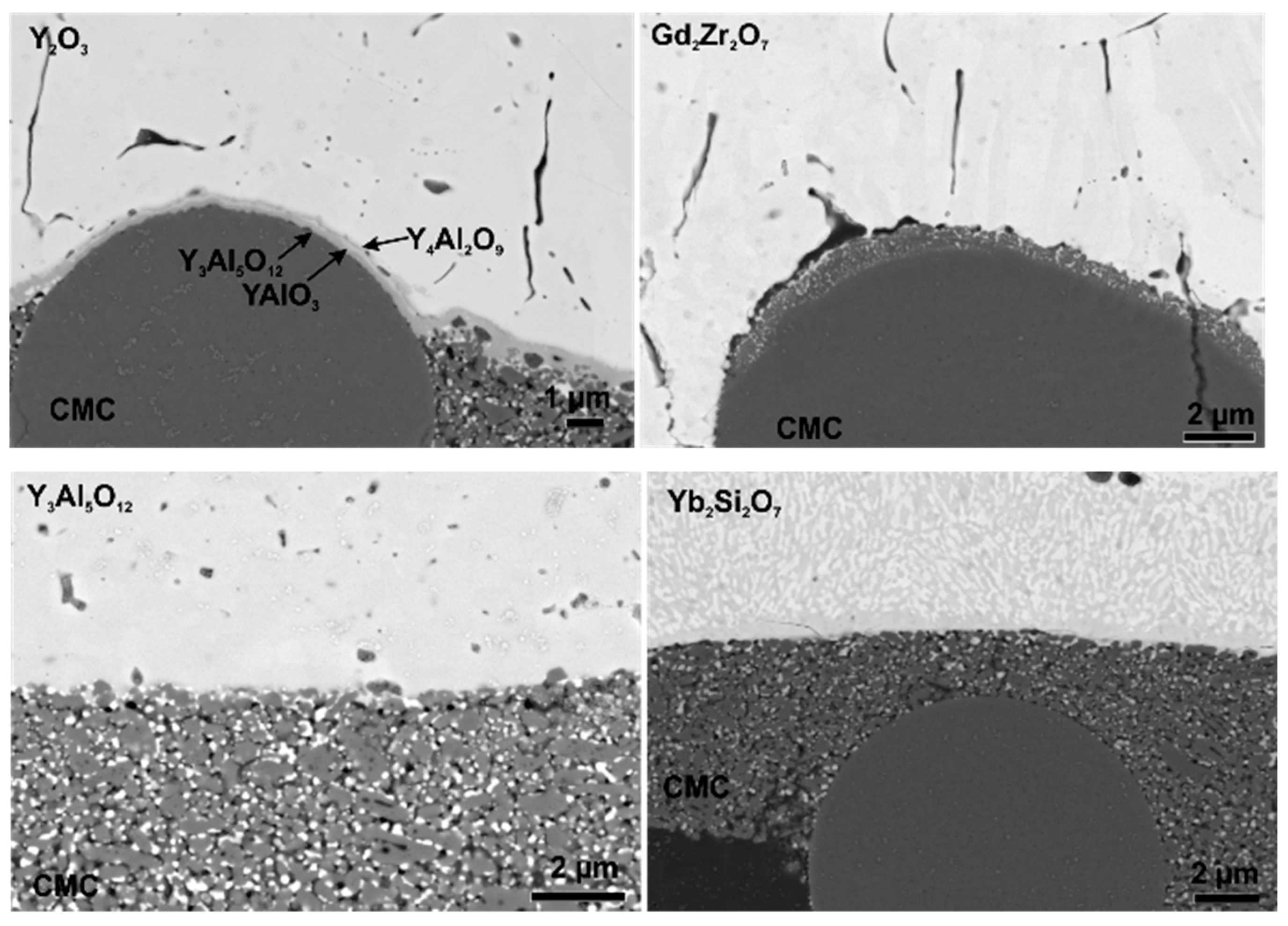
The as-sprayed samples were subjected to furnace thermal cycling, the used temperature program consists of four 20 h cycles at 1200 °C. SEM images of cross sections of samples in the as-sprayed state and after thermal cycling are presented in Figure 4. Additionally, higher magnification images of the interface region of the coatings are presented in Figure 5.
The obtained Y2O3 coatings were dense and fully crystalline. The adhesion of the Y2O3 samples seems to be quite good, after heat treatment no signs of cracks or delamination are observed. The good adhesion can be attributed small TEC mismatch and phase stability, resulting in low driving force for delamination. Another reason for the good adhesion is the formation of yttrium-aluminates at the coating substrate interface leading to chemical bonds between coating and substrate [25]. In Figure 5 the formation of several yttrium-aluminates known from the phase diagram [26] can be observed.
The SEM images of the Gd2Zr2O7 coatings show dense and homogenous coatings in the as-sprayed state. Figure 5 shows the coating substrate interface in detail. After thermal cycling no sign of a reaction between Gd2Zr2O7 and Al2O3 was observed. This is in contrast to Lakiza et al. [27] and Leckie et al. [28] The phase diagram of Gd2Zr2O7, presented by Lakiza et al. [27], suggests formation of gadolinium-aluminates such as GdAlO3 and Gd4Al2O9. The reaction between Gd2Zr2O7 and Al2O3 to GdAlO3 was observed in a study by Leckie et al. [28]. The absence of this reaction in this study can be explained by bad wetting which causes only small contact areas to the substrate, as a consequence the reaction is inhibited. However, after heat treatment the coating was delaminated at the interface (marked by arrows in Figure 4). This can be explained by the TEC mismatch (∆CTE = 3 × 10⁻⁶ K−1, see Equations (2) and (3)) and bad wetting of the relative smooth substrate (Ra = 2.6 µm).
The SEM images of the Y3Al5O12 coating confirm the presence of secondary phases within the coating. Furthermore, large round pores can be observed in the Y3Al5O12 coatings. The high porosity is not favourable for an EBC, as pores and cracks increase the permeability for water vapor. Despite the low TEC mismatch (∆CTE = 3 × 10⁻⁶ K−1), the Y3Al5O12 coatings tend to fail during thermal cycling. This can be explained by the high amorphous content of the APS-Y3Al5O12 coatings. Thermal treatment leads to crystallization and phase transformation of the coating; this causes stress within the material leading to the formation of segmentation and delamination cracks. The formation of large pores in Y3Al5O12 coatings was also reported by Weyant et al. [29], a dependence between crystallization, substrate temperature and porosity was assumed. According to the phase diagram [30] of Y2O3 and Al2O3, a reaction between coating and substrate is not expected. The SEM image of the Y3Al5O12 - Al2O3 interface (Figure 5) shows that unlike with Y2O3, no reaction occurs between substrate and coating.
The cross-sections show that the disilicate coatings have a lot of pores and consist of several phases, which is, again, not favourable for an EBC. Furthermore, crystallization problems occurred, as described for the Y3Al5O12 coatings. Due to the high TEC mismatch (∆CTE = 5.2 × 10⁻⁶ K−1, see Equations (2) and (3)) and the stresses that arise during crystallization, these coatings were delaminated during thermal treatment. According to the phase diagram of Yb2O3-SiO2-Al2O3 [31], the formation of mullite (Al6Si2O13) and ytterbium-aluminates (Yb4Al2O9, Yb3Al5O12) during thermal cycling is possible. However, no reaction between coating and substrate was observed (see Figure 5). The absence of a reaction layer may be attributed to the loose contact between coating and substrate as well as the high TEC mismatch and the resulting premature coating delamination.
Due to the high coating crystallinity, phase purity and coating density, Gd2Zr2O7 and Y2O3 were chosen for further experiments. Although Gd2Zr2O7 has a higher CTE mismatch, it is a desirable top coat due to its excellent CMAS stability. In order to increase the coating adhesion different methods of surface preparation were carried out before spraying.
First, samples of the Al2O3/Al2O3 CMC were mechanically treated to increase the surface roughness. Some samples of the Al2O3/Al2O3 CMC were ground, others were grit-blasted. Both methods were able to increase the surface roughness from 2.6 µm to 5.1 µm and 15 µm, respectively. The samples were coated and subsequently furnace cycled for 4 × 20 h at 1200 °C. SEM images of cross-sections of the as-sprayed Y2O3-coatings as well as furnace cycled samples are shown in Figure 6. The results show that the mechanical pre-treatment damaged the ceramic substrate to such an extent that even Y2O3 coatings failed. Unlike in the study of Gérendas et al. [32], mechanical pre-treatment was not able to achieve sufficient coating adhesion on this CMC.
Laser ablation was used for surface structuring without damaging of the substrates. The positive effect of laser surface structuring of Al2O3/Al2O3 CMCs on coating adhesion was recently demonstrated by Gatzen et al. [
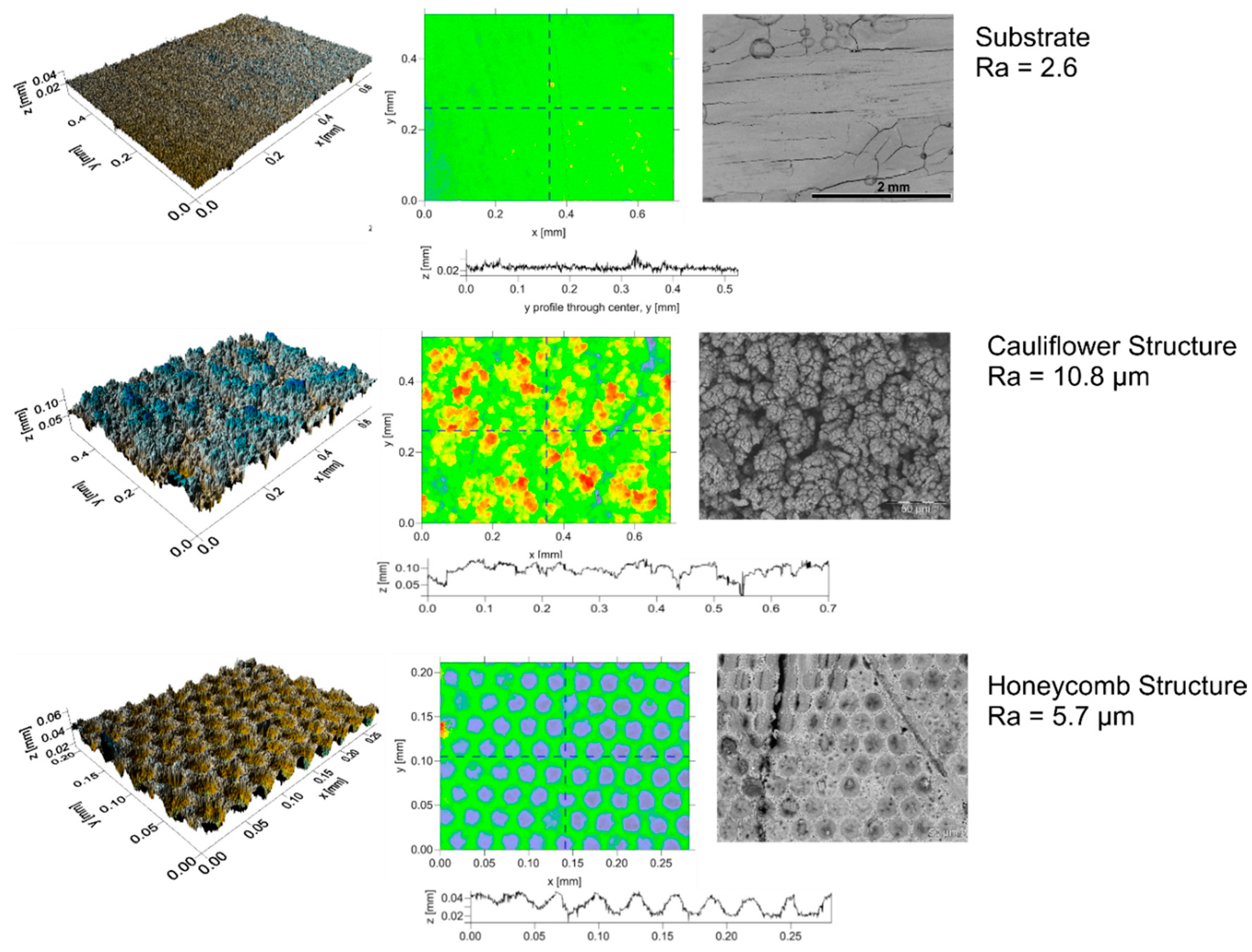
23]. Two different structures were chosen for this study: honeycomb and cauliflower structure. Both structures are illustrated in Figure 7.
The untreated substrate has a roughness of about 2.6 µm and a homogenous smooth surface. Few cracks and pores at the surface offer possibilities for clamping. The cauliflower like surface structure comprises an irregular and inhomogeneous surface of re-solidified alumina. An average roughness of 10.8 µm was achieved with this pattern. The honeycomb structure shows well- defined holes close to each other. A roughness of about 5.7 µm was measured for this pattern. Both surface structures offer more possibilities for clamping, therefore, an increase in lifetime is expected especially for Gd2Zr2O7 coatings.
After structuring the samples were coated with Y2O3 and Gd2Zr2O7. SEM images of the coated and thermally cycled samples are shown in Figure 8. Both coatings could infiltrate the voids in between the substrate structure. The surface structures, especially the cauliflower structure, allow interlocking of the coating. After thermal cycling no cracks or delamination occurred in the Y2O3 coating-substrate-system. This shows that in contrast to grit-blasting and grinding, laser structuring of the CMC does not weaken the ceramic matrix. Furthermore, after thermal cycling of the laser-structured Gd2Zr2O7 coated samples, the coating-substrate interface shows no delamination cracks. This is a significant improve, compared to the coating on untreated substrates. Although the energy release rate is high in these coatings with high mismatch (see Equations (2) and (3)), the laser structuring of the samples proofed to be beneficial for the coating adhesion (e.g., the critical energy release).
In addition, a third method of adhesion improvement was tested for Gd2Zr2O7: the usage of an Y2O3-bondcoat. For this, the untreated substrate was first coated with Y2O3 and then coated with Gd2Zr2O7. This double layer coating system is referring to the double layered TBCs as published by Vaßen et al. [33]. The Y2O3-bondcoat helps to buffer to some extent especially at edges the CTE mismatch between the CMC and Gd2Zr2O7. Furthermore, the Y2O3 coating is known to be good adherent on Alumina CMCs [25] and offer a rough surface for the Gd2Zr2O7 coating. Using Y2O3 as an interlayer between substrate and Gd2Zr2O7 also proofed to increase the coating adhesion as well.

3.2. Development of APS Y2SiO5 coatings

According to Figure 1 Y2SiO5 has an excellent water vapor resistance and is therefore considered as appropriate EBC material [34,
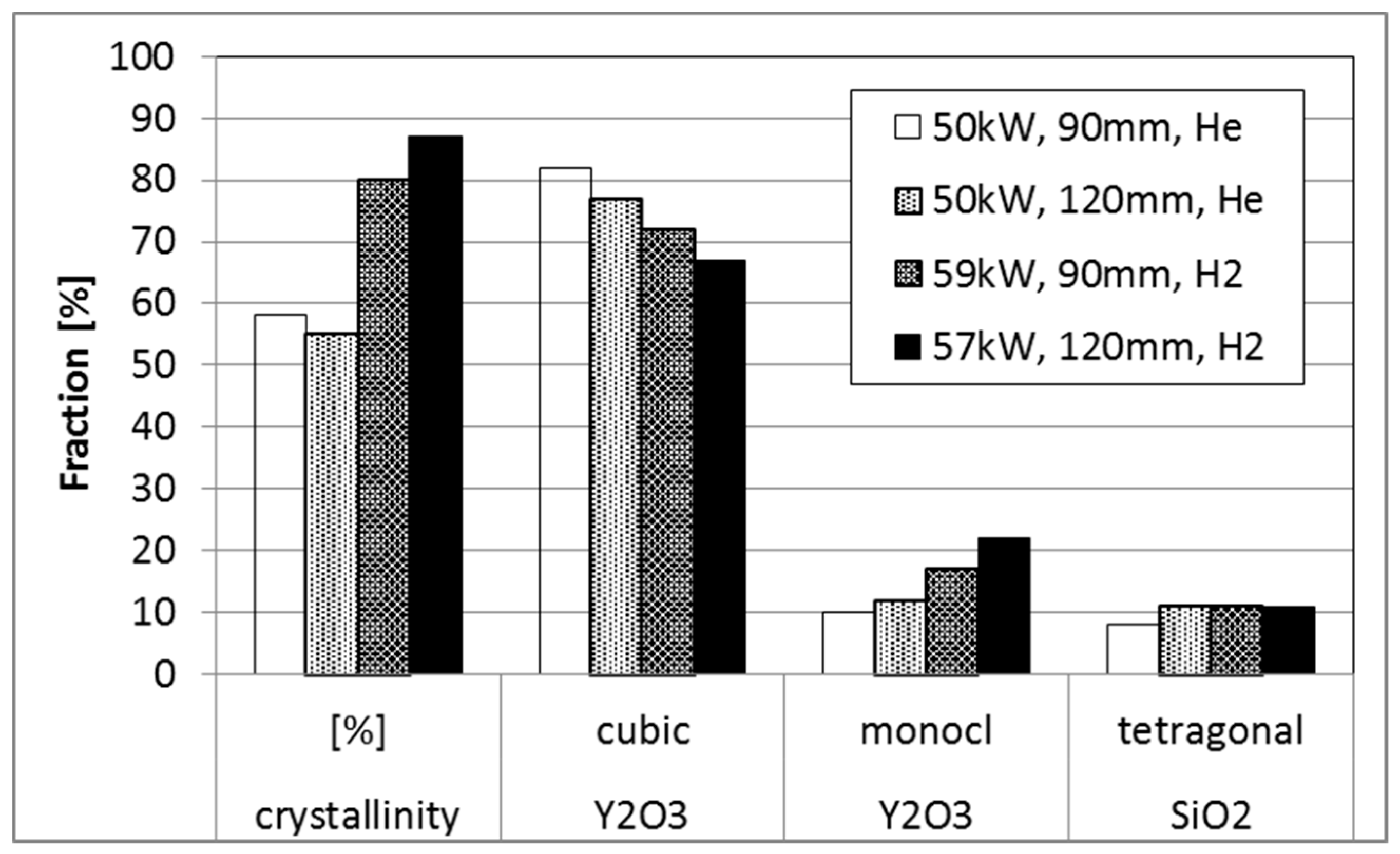
35]. In this investigation only rather hot APS spraying conditions are investigated for this material. The density of all the coatings manufactured by the investigated conditions (see Table 2) has been rather high, more interesting is the phase content which shows remarkable differences (see Figure 9). Compared to the He as secondary gas, hydrogen increased the plasma enthalpy which leads to higher substrate temperatures (750°C) and increases the amount of crystallization. The comparable amount of SiO2 in all coatings might indicate no significant differences in the silica loss during spraying (although the amorphous content is not considered).
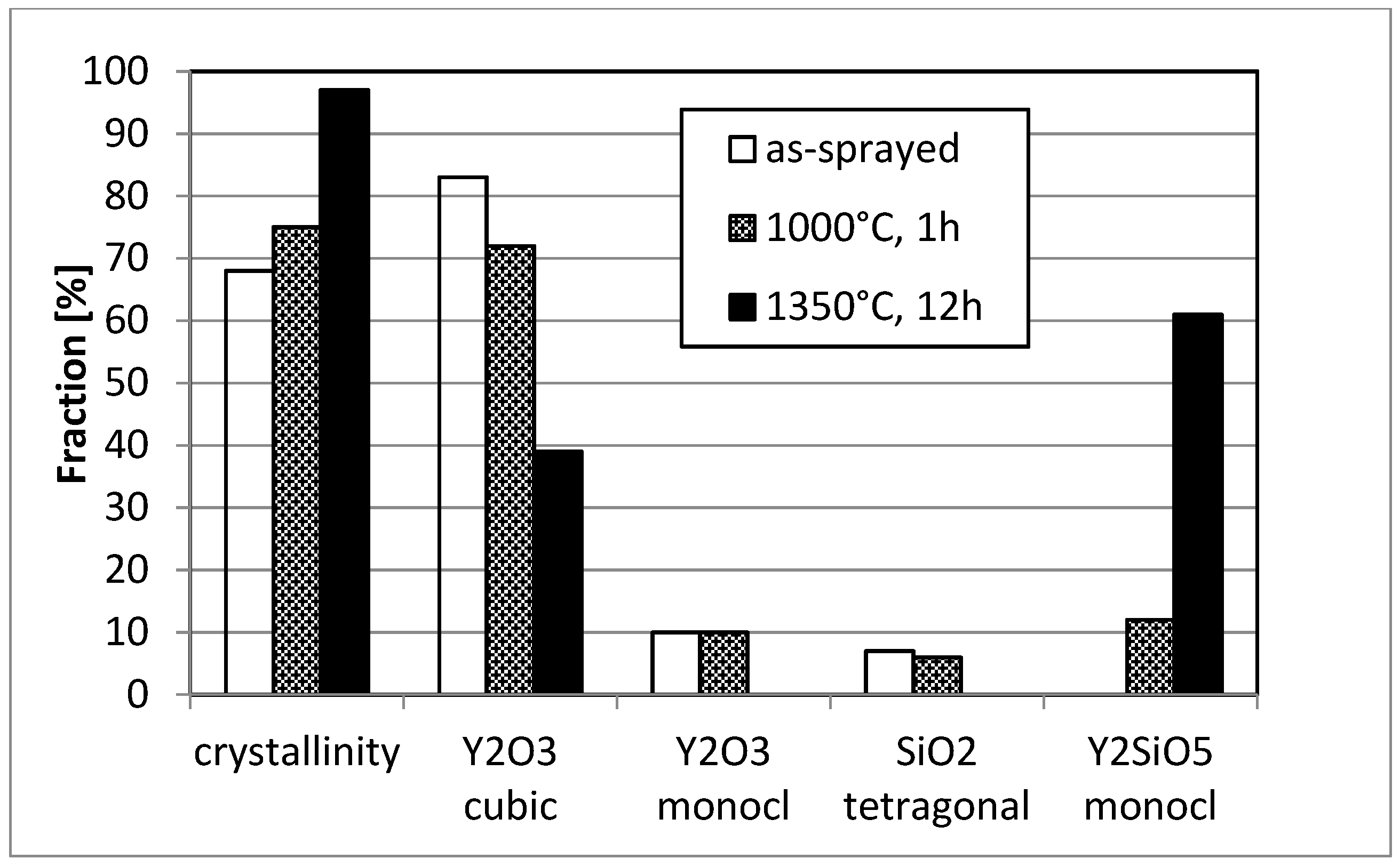
Due to the highest crystallinity, the condition D with hydrogen and long stand-off distance (condition D) was used for further studies and coatings on C/SiC substrates were prepared. In Figure 10 SEM micrographs of the coatings in the as-sprayed condition and after annealing for 12 h at 1350 °C. First of all, the coating is also after the heat-treatment well-adherent. This indicates that the TEC mismatch (see Equations (2) and (3)) between coating and substrate seems to be not extremely detrimental (although the material would fit even better to Ox/Ox CMC substrates). In addition, also the phase transformation at 850 °C and the strongly anisotropic expansion of Y2SiO5 [36] obviously does not significantly affect coating integrity.
In addition, the size of the segmentation and micro cracks is largely reduced due to sintering, some segmentation cracks are even no longer penetrating through the whole coating. Also the phase distribution changed significantly. While in the as-sprayed condition rather large regions with low and high silicon content appear (stemming from the impinging particles which have lost silicon during spraying mainly at their surface), the annealed coating shows much finer phases consisting of cubic Y2O3 (bright) and monoclinic Y2SiO5 (darker). The evolution of phases is shown in Figure 11 measured by XRD and using Rietveld refinement. Obviously, a short-term annealing at 1000 °C is not sufficient to form the equilibrium phases. As the coating is rather dense, the Y2O3 as a second phase has a reasonable corrosion resistance (Figure 1) and the microstructure probably will show some particulate toughening effects, the found coating is expected to perform good as EBC.

3.3. Yb2Si2O7 Coatings Manufactured by Different Thermal Spray Techniques for SiC/SiC Substrates

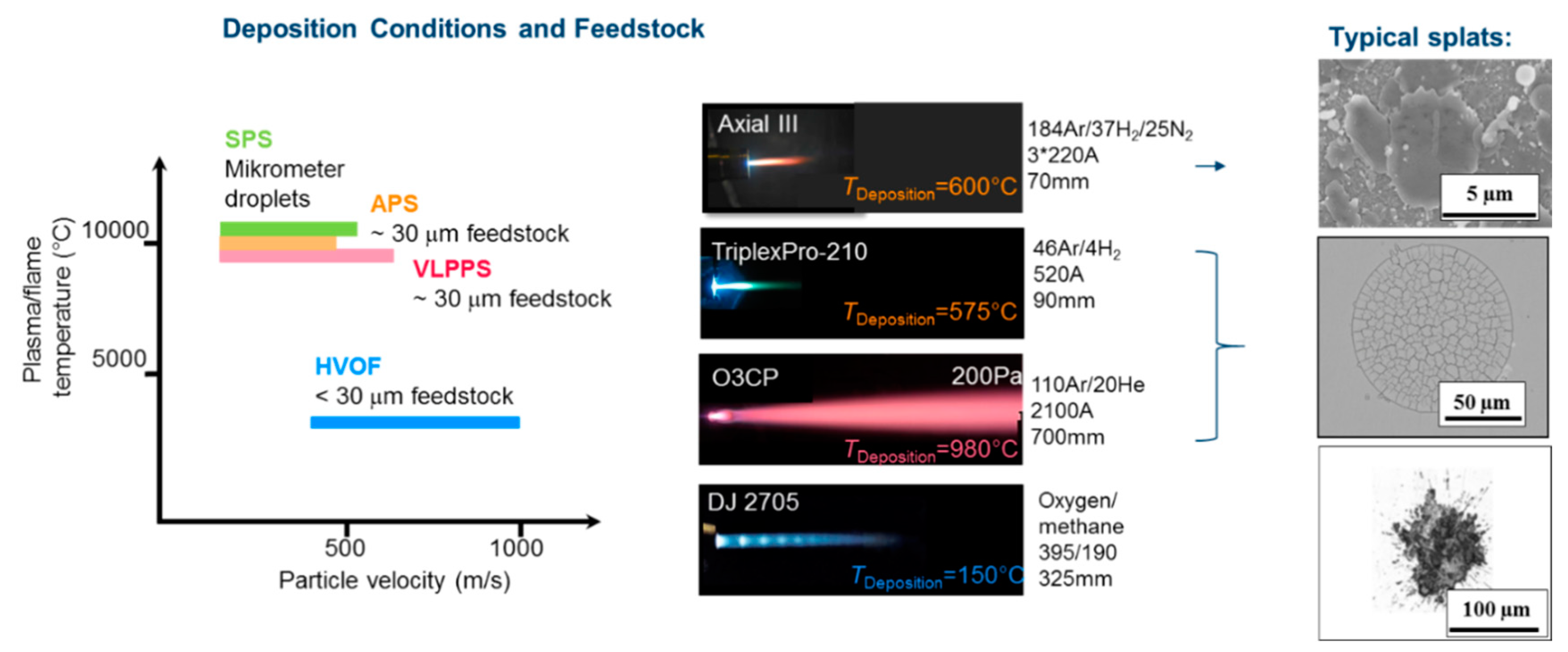
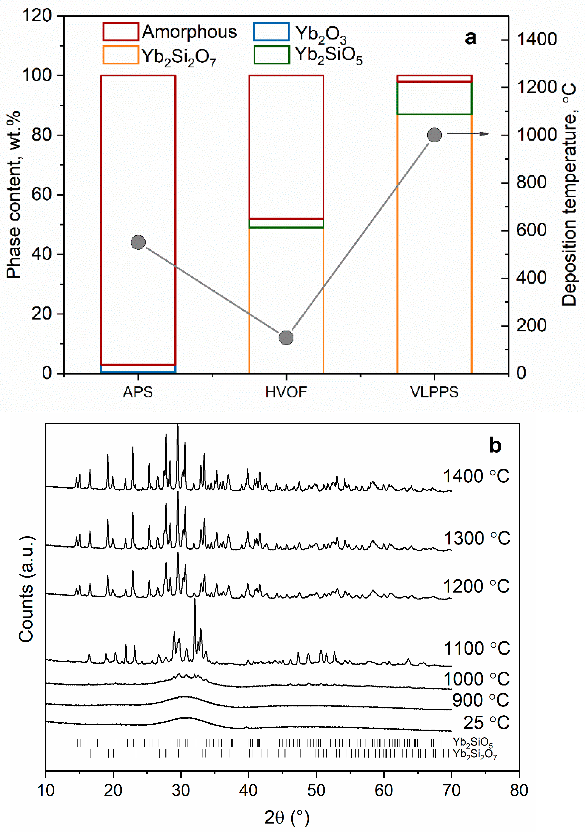
Figure 12 shows the phase composition of APS, HVOF and VLPPS coatings deposited from different particle size fractions of the same Yb2Si2O7 feedstock. The main differences between the different methods are melting degree of the sprayed particles and deposition temperatures which define the crystallinity of the coatings as well as the degree of Si evaporation during spraying.
In APS and VLPPS, as a result of the high heat transfer from plasma to the particles, particles melt, impact on the substrate in the molten state and rapidly solidify on the substrate. High plasma powers were selected in the deposition of EBCs with APS (57 kW) and VLPPS (90 kW) as a dense microstructure consists of well-flattened particles with good interfacial contact is aimed. While high plasma powers ensure melting of particles in the plume, it also leads to a significant amount of Si-evaporation from Yb2Si2O7 during spraying. As a result of that, Si-depleted secondary phases such as Yb2SiO5 and Yb2O3 are found in the as-sprayed coatings as shown in the Figure 12a. Furthermore, due to quenching of the molten particles on the substrate, that is at nearly room temperature if not pre-heated by plasma plume, crystallization of the glass forming silicates is suppressed and the amorphous phase is formed. The APS experiments carried out in order to increase the SiC substrate temperature by heating with plasma prior to deposition revealed that for a substrate size of 50 × 50mm2, it is possible to increase the substrate temperatures up to about 800–900 °C however the temperature rapidly goes down to 500–550 °C till the deposition starts. As shown in Figure 12a, this deposition temperature range was found to be not sufficient to activate and complete the crystallization of the coating. According to HT-XRD analysis of amorphous plasma-sprayed Yb2Si2O
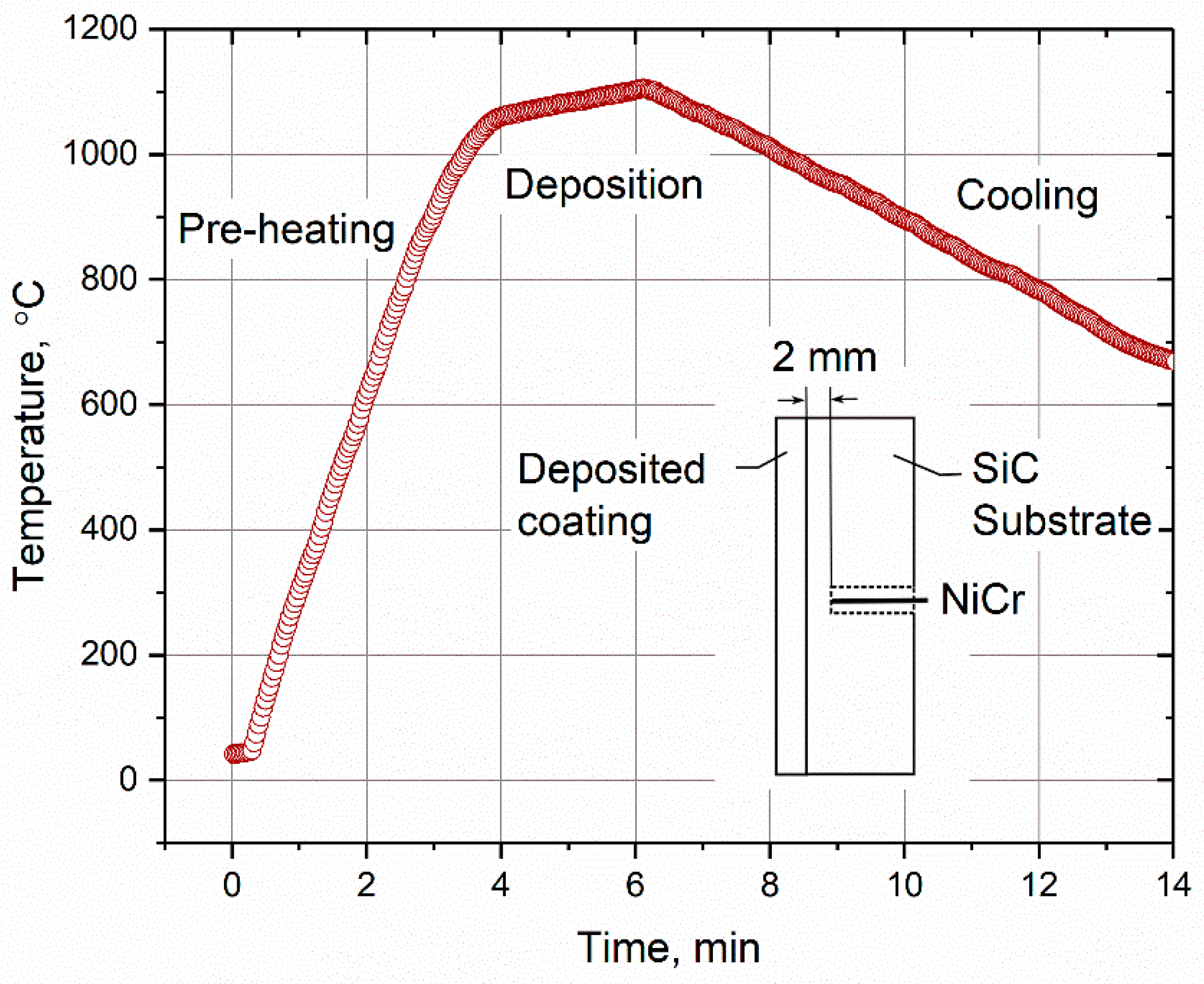
7 particles, which were collected in water and dried subsequently at 70 °C, the crystallization temperature of the material was found to be above 1000 °C, which explains the amorphous structure of the coating deposited at about 550 °C. Aiming at a higher substrate temperature as well as slower cooling rates in order to provide higher energy and longer time for the atoms to rearrange into the crystalline state, VLPPS experiments were conducted in the controlled atmosphere chamber (2 mbar). It was found that it is possible to reach substrate temperatures higher than 1000 °C (Figure 13) owing to higher plasma power of the O3CP torch as well as to retain it till the deposition starts due to reduced heat transfer under vacuum. To prolong the high-temperature phase after deposition for some minutes, the coating was kept to be heated using the plasma plume and by this procedure, highly crystalline coatings could be produced as shown in Figure 12a. Nevertheless, it should be mentioned that Si-evaporation remains a problem as more than 10 wt.% Yb2SiO5 was detected in the VLPPS coatings.
The HVOF process yields lower flame temperatures in comparison with the plasma spray processes as the flame is generated by combustion. As a result of that, particle temperatures as well as the deposition temperature are lower. Nonetheless, using the HVOF process, Yb2Si2O7 coatings with higher crystallinity in comparison with the APS could be manufactured because of the deposition of un-melted or partially molten particles. This was avoided in the plasma spray processes as un-melted particles increase the porosity levels in the coatings due to imperfect contact regions as well as the porous morphology of the particle itself. In the HVOF process, however, not the porosity stemming from the particle morphology, but the porosity caused by the bad contact can be minimized thanks to very high flame velocity and, thus, the high momentum transfer to the particles in the flame. If the brittle oxide particles are completely un-melted, they break upon high-velocity impact on the substrate, however, if only their core is un-melted and the outer surface is molten, they can adhere on the substrate or on the previously deposited layers. To reach such particle conditions, sensitive process optimizations are required in terms of fuel–oxygen stoichiometry, total gas flow, powder feed rate, stand-off distance, and particle size distribution. Details of these investigations can be found elsewhere [18] and HVOF microstructure will be further discussed in the following. Consequently, these coatings own higher crystallinity regardless of the lower deposition temperature in the process as un-melted part of the particles remain crystalline. An added benefit of low flame temperature is diminished Si-evaporation from the particles during spraying. It can be seen from Figure 12a that the detected Yb2SiO5 content from about 50 wt.% crystalline HVOF coating is about 5 wt.% which fits well to the feedstock composition although of course the large amorphous content has to be considered.
The microstructure of the coatings sprayed from Yb2Si2O7 feedstock with APS, HVOF and VLPPS processes can be seen in Figure 14. The two APS coatings (a,b) that were deposited at different temperatures (Figure 14a is the “standard” APS sample and b is deposited at a higher temperature, further details are discussed below) have vertical cracks running through the thickness of the coatings which is associated with the higher thermal stresses in these coatings due to the significant amount of Yb2SiO5 content (about 30 wt.% in these coatings determined after crystallization heat treatment). Because thermal expansion coefficient of Yb2SiO5 (7.5 × 10⁻⁶ °C−1) is larger than that of the Yb2Si2O7 (4.7 × 10⁻⁶ °C−1) as well as the SiC/SiC substrate (5.1 × 10⁻⁶ °C−1) [37]. This leads to greater tensile thermal stresses in the oxide coating after cooling, along with the tensile quenching stresses, which induce the vertical cracking. The high amorphous content in the APS layer would even further increase the CTE mismatch, however simultaneously due to a reduced Young´s modulus of the amorphous state, the effect on the stress level might be limited. Therefore, as cracks are not desired in the EBC microstructure, it is of crucial importance to minimize Si- evaporation during spraying.
Both APS coatings (Figure 14a,b) were sprayed at similar conditions but sample size in (b) was very small (3 × 3.8 × 36 mm3) and as a result of that a maximum deposition temperature of about 900 °C could be reached for this particular sample. Therefore, in contrast to standard size APS sample that was analysed in the preceding section and shown in Figure 14a, the APS coating shown in Figure 14b is highly crystalline (76 wt.%). The porosity content of the two APS coatings are also dissimilar, i.e., the coating (a) is significantly denser than the coating (b). This difference between the microstructures was associated with the higher crystallinity in the coating (b). Seemingly, heterogeneous nucleation takes place at the splat boundaries during cooling while the centre of the splats remains amorphous. As density increases in the crystallizing zone, the volume is reduced which induces elastic tensile stresses within the amorphous region. Pores within the splat, therefore, nucleate when these stresses are large enough. Other relevant theories to the formation of pores are discussed elsewhere [20].
No vertical cracking was observed in the fairly dense HVOF layer (Figure 14c), presumably due to lower Yb2SiO5 content and hence reduced thermal stresses in the process as a result of the lower particle and deposition temperatures, respectively. However, isothermal thermal cycling experiments revealed that the adhesion of the HVOF oxide layer on the Si bond coat is poor because the HVOF layer partially delaminated only after few cycles [18]. The short lifetime of the layer was attributed to the presence of un-melted particles at the interface wherein the cracks can easily propagate. The un-melted particles can be avoided for instance by decreasing the particle size of the feedstock but that means higher amorphous content and Yb2SiO5 phase in the layer at the same time. Figure 14d shows the microstructure of a VLPPS layer that is free of vertical cracks, dense and also crystalline in the as-sprayed state, which makes it a very promising method developed for EBC manufacturing in Jülich. High deposition temperatures (min. 1000 °C) and moderate cooling rates (approx. 55 K/min) in the process as shown in Figure 13 evidently helps for crystallization as well as for stress relaxation in the layer. Further investigations are ongoing in this direction to understand the effect of deposition temperature and cooling rates on crystallization kinetics and related mechanical properties in the layer, as well as the stress state in the EBC system.
While a variety of coating morphologies can be obtained with thermal spray processes, characteristics of the coatings, typically the size of microstructural features, is controlled by the used feedstock [38]. For example, the size of intersplat pores is directly depending on the size and shape of powdery feedstocks. Since a well flowable powder in the size range of about 10–100 μm is usually applied for conventional plasma spraying, there is a minimum size for application of powdery feedstock. Suspension plasma spray would be one of alternative processes for conventional ones in this context. Suspension plasma spraying is one of the rather new thermal spray techniques, which has a liquid feed stock and relatively higher plasma power compared with conventional ones. Especially, SPS could supply a great diversity in microstructural features from columnar and porous to bulk-like dense ones [39,40]. Main processing parameters, such as gun power, spraying distance, roughness, and particle size distribution in suspension, would play an important role in controlling the microstructures fabricated by SPS.
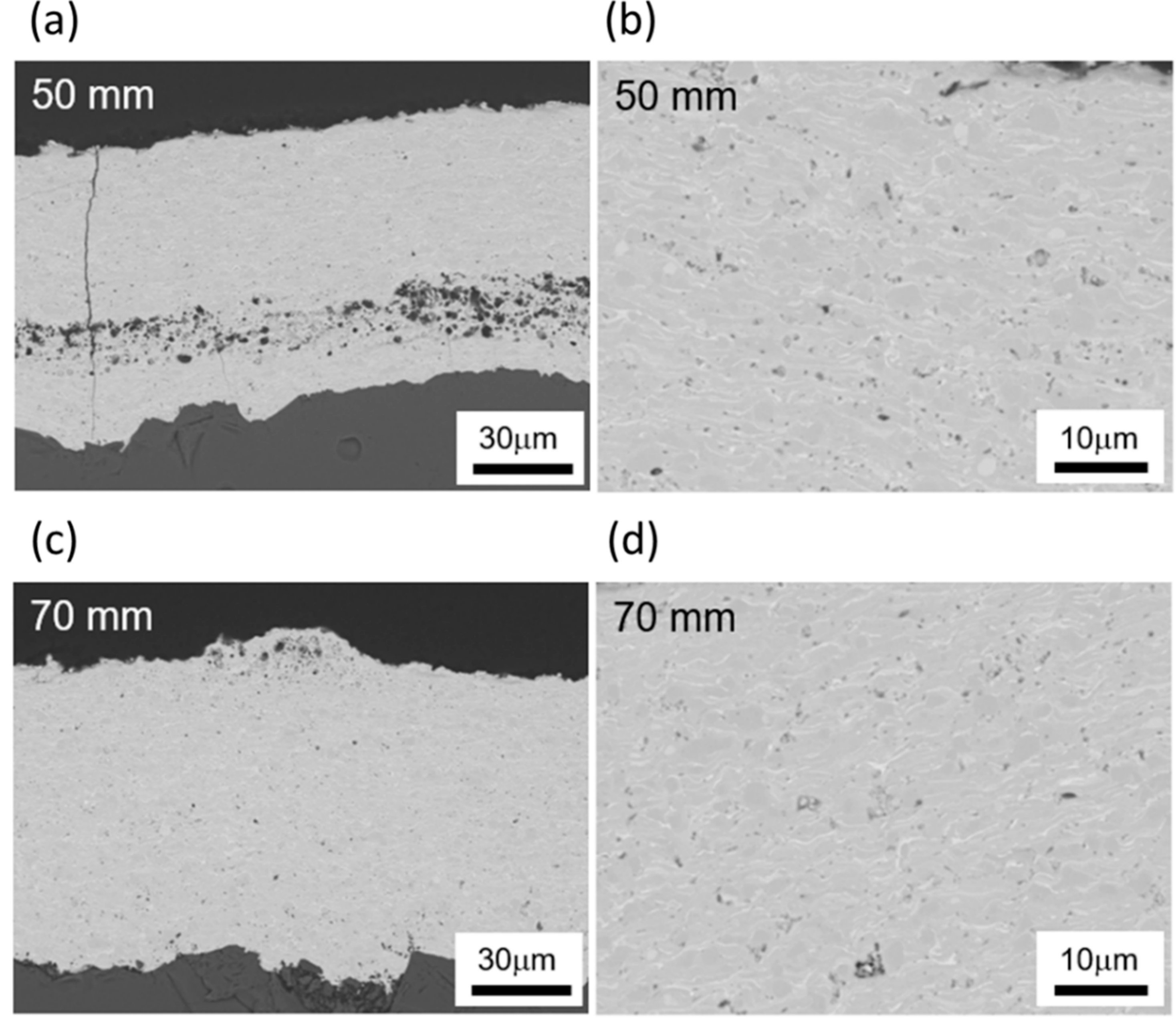
Figure 15 shows the cross-sectional microstructures of Yb2Si2O7 coatings fabricated by using the SPS technique with different spraying distances of 50 and 70 mm. As seen especially in the higher magnification images, bulk-like dense microstructure can be obtained within this work regarding gun power, spraying distance and particle size distribution in suspension feedstock. Vertical cracks in the coating microstructure were inevitable because of tensile stress from rapid cooling after spraying as can be seen in Figure 15c.
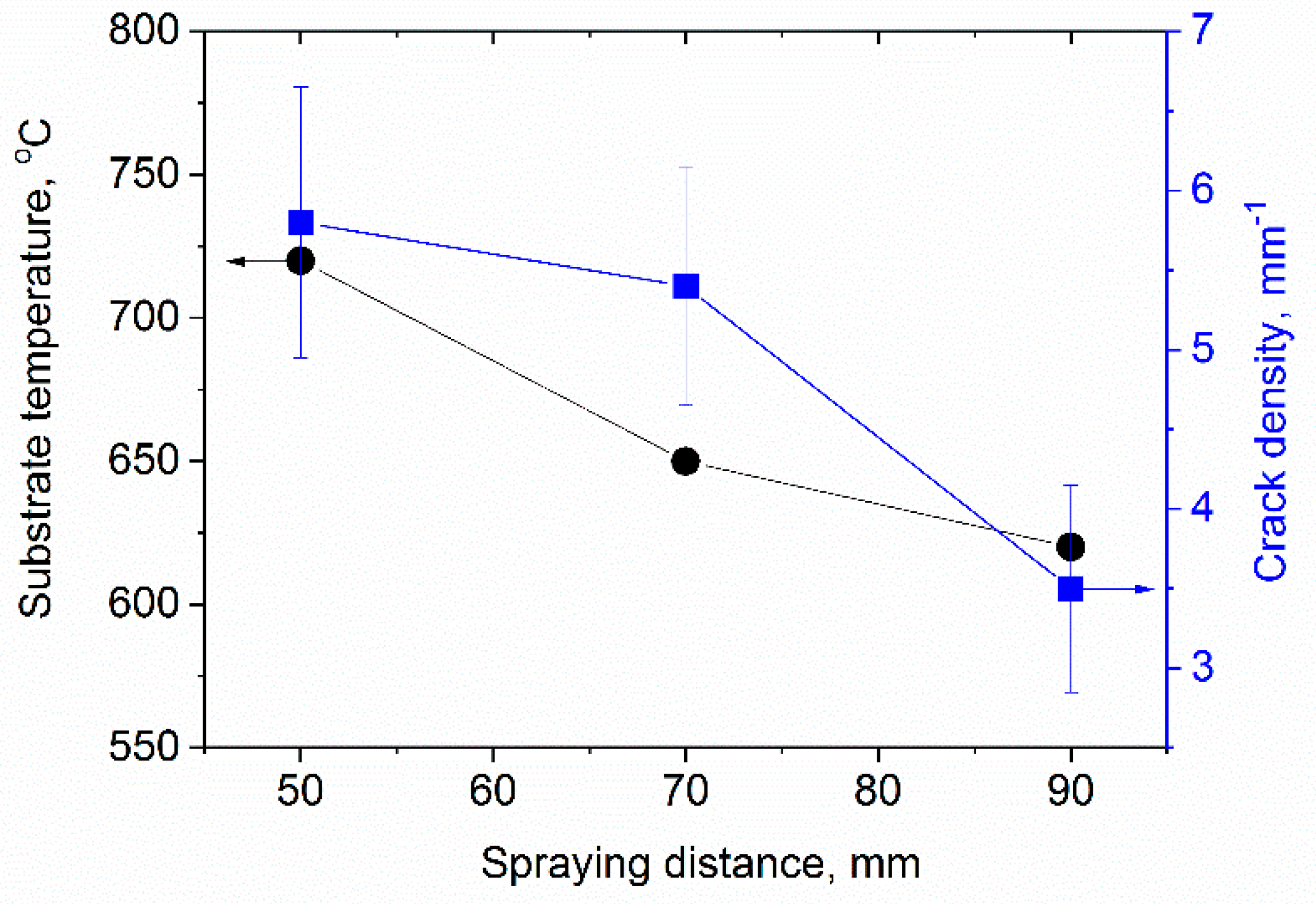
Figure 16 reveals how the stand-off distance influences the substrate temperature and by that e.g., the degree of crystallization. Shorter stand-off distances give higher temperatures and by that also better splat bonding and reduced relaxation, which give a higher segmentation crack density. 
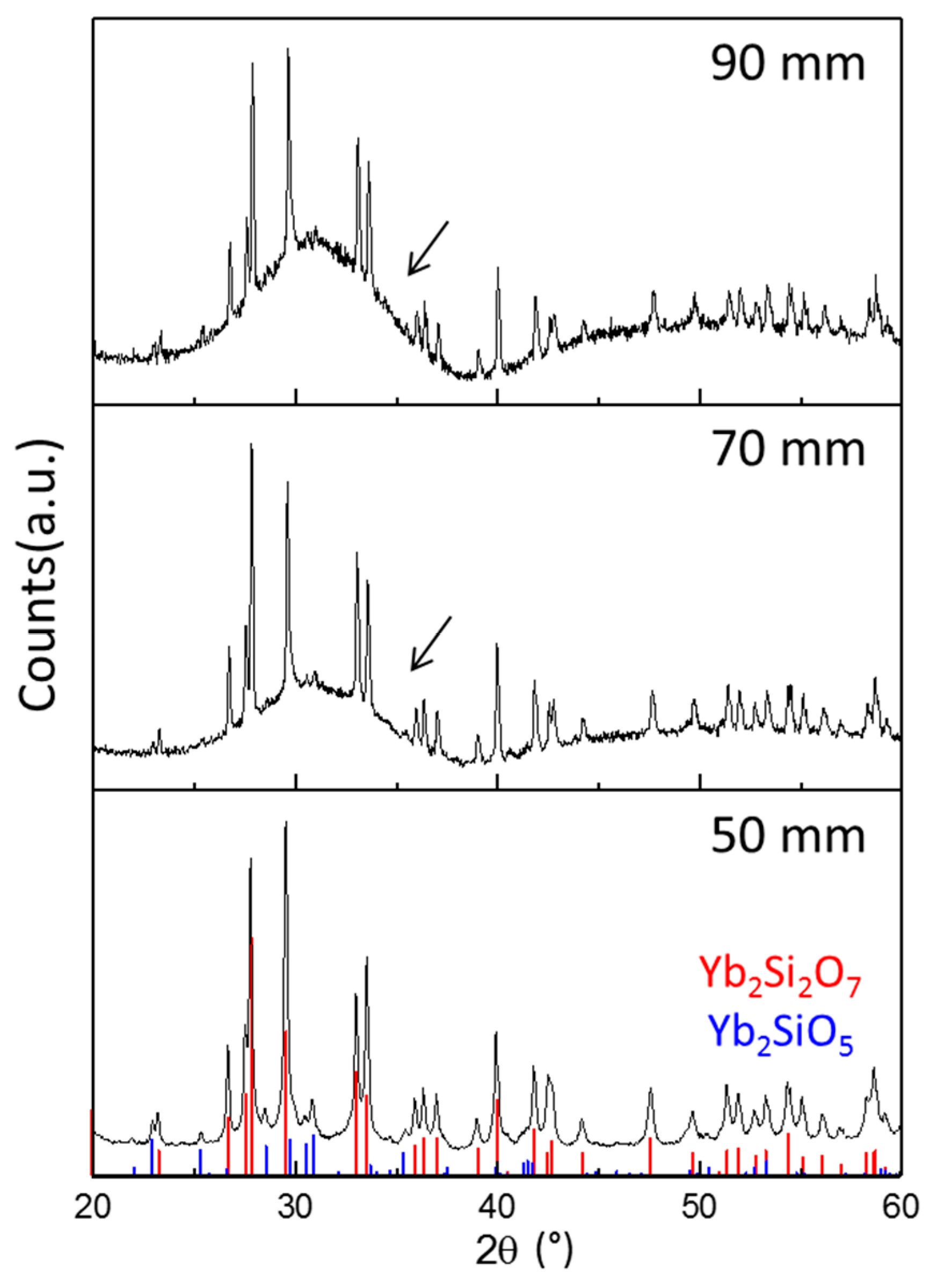
Figure 17 shows the X-ray diffraction patterns of Yb2Si2O7 coatings fabricated by using the SPS technique with different spraying distance. Considerable amounts of the amorphous phase were observed from EBC with long spraying distance (90 mm). In the case of short spraying distance (50 mm), the degree of crystallinity was around 80%, which was calculated from the areal intensity ratio between crystalline peaks and amorphous humps of XRD.

4. Conclusions

This study summarizes insights into the development of EBCs for both oxide- and non-oxide-based CMCs. Results of coating experiments with different ceramic powders on an Al2O3/Al2O3 CMC were presented; the samples were furnace cycled to test the high temperature behaviour. Coatings of Y2O3 and Gd2Zr2O7 showed promising results, as they were crystalline and dense in the as-sprayed state. Y2O3 coatings showed excellent adhesion due to the formation of chemical bonds between coating and substrate. In contrast to this, Gd2Zr2O7 coatings tend to fail during cycling because of bad contact between coating and substrate. The coating adhesion could be significantly increased by laser structuring of the CMC before coating.
Y2SiO5 coatings could be prepared with rather high crystallinity (nearly 70%). Heat treatment led to the formation of a fine-grained microstructure with the major phase Y2SiO5 and a considerable amount of Y2O3 without delamination after cooling.
Yb2Si2O7 coatings have been produced by different thermal spray process, namely, APS, HVOF, VLPPS, and SPS. APS can deliver dense coatings with a high degree of amorphous phase content. HVOF gives rather crystalline coatings with acceptable porosity levels, VLPPS gives even better coatings. Furthermore, SPS can give a high degree of crystallinity, however segmentation cracks are difficult to avoid.
A summary of the outcome reflecting the actual situation as seen in our institute is given in Table 4. So, our message is that also other thermal spray methods than APS can be used to obtain promising EBCs. Certainly, further improvements of processes can change the ranking in this evaluation.

Author Contributions

R.V.: writing—original draft preparation, supervision, review and editing; E.B.: investigation, writing—original draft preparation; C.G.: investigation, writing—original draft preparation; S.K.: investigation, writing—original draft preparation; D.E.M.: supervision, review and editing; O.G.: supervision, review and editing.

Funding

This research received no external funding.

Acknowledgments

The authors acknowledge the contributions of the following colleagues in our institute: Ralf Laufs, Frank Kurze and Mr. Karl-Heinz Rauwald for the invaluable assistance during plasma spraying and Georg Mauer for valuable discussions of thermal spray results. We also would like to thank Doris Sebold for SEM analysis and Yoo Jung Sohn for the extended XRD analysis. We also appreciate the support of Sigrid Schwartz-Lückge and Mark Kappertz in sample preparation and characterization.

Conflicts of Interest

The authors declare no conflict of interest.

References

  1. Bansal, N.P. Handbook of Ceramic Composites; Kluwer Academic Publishers: Boston, MA, USA; Dordrecht, The Netherlands; London, UK, 2005. [Google Scholar]
  2. Steibel, J. Ceramic matrix composites taking flight at GE Aviation. Am. Ceram. Soc. Bull. 2019, 98, 30–33. [Google Scholar]
  3. Gerendás, M.; Wilhelmi, C.; Machry, T.; Knoche, R.; Werth, E.; Behrendt, T.; Koch, D.; Hofmann, S.; Göring, J.; Tushtev, K.; et al. Dwvelopment and Validation of Oxide/Oxide CMC Combustors within the Hipoc Program. In Proceedings of the ASME Turbo Expo 2013, San Antonio, TX, USA, 3–7 June 2013. [Google Scholar]
  4. Opila, E.J.; Hann Jr, R.E. Paralinear Oxidation of CVD SiC in Water Vapor. J. Am. Ceram. Soc. 1997, 80, 197–205. [Google Scholar] [CrossRef]
  5. Herrmann, M.; Klemm, H. Corrosion of Ceramic Materials. In Comprehensive Hard Materials; Sarin, V.K., Ed.; Elsevier: Oxford, UK, 2014. [Google Scholar]
  6. Zhu, D.; Fox, D.S.; Bansal, N.P.; Miller, R.A. Advanced Oxide Material Systems for 1650 °C Thermal/Environmental Barrier Coating Application; NASA Technical Report 20050199717; NASA Glenn Research Center: Cleveland, OH, USA, 2004.
  7. Lehmann, H.; Pitzer, D.; Pracht, G.; Vaßen, R.; Stöver, D. Thermal Conductivity and Thermal Expansion Coefficients of the Lanthanum Rare-Earth-Element Zirconate System. J. Am. Ceram. Soc. 2003, 86, 1338. [Google Scholar] [CrossRef]
  8. Fritsch, M.; Klemm, H.; Herrmann, M.; Michaelis, A.; Schenk, B. The water vapour hot gas corrosion of ceramic materials. Ceram. Forum Int. 2010, 87, 11–12. [Google Scholar]
  9. Fritsch, M.; Klemm, H.; Herrmann, M.; Schenk, B. Corrosion of selected ceramic materials in hot gas environment. J. Eur. Ceram. Soc. 2006, 26, 3557–3565. [Google Scholar] [CrossRef]
  10. Fritsch, M. Heißgaskorrosion Keramischer Werkstoffe in H2O-Haltigen Rauchgasatmosphären, Fraunhofer IRB Verlag; TU Dresden: Dresden, Germany, 2007. [Google Scholar]
  11. Fauchais, P.L.; Heberlein, J.V.; Boulos, M.I. Thermal Spray Fundamentals; Springer: New York, NY, USA, 2014. [Google Scholar]
  12. Li, C.-J.; Yang, G.-J.; Li, C.-X. Development of Particle Interface Bonding in Thermal Spray Coatings: A Review. J. Therm. Spray Technol. 2013, 22, 192–206. [Google Scholar] [CrossRef]
  13. Vaßen, R.; Hathiramani, D.; Mertens, J.; Haanappel, V.; Vinke, I. Manufacturing of high performance solid oxide fuel cells (SOFCs) with atmospheric plasma spraying (APS). Surf. Coat. Technol. 2007, 202, 499–508. [Google Scholar] [CrossRef]
  14. Guo, H.B.; Vaßen, R.; Stöver, D. Atmospheric plasma sprayed thick thermal barrier coatings with high segmentation crack density. Surf. Coat. Technol. 2004, 186, 353–363. [Google Scholar] [CrossRef]
  15. Richards, B.T.; Wadley, H.N.G. Plasma spray deposition of tri-layer environmental barrier coatings. J. Eur. Ceram. Soc. 2014, 34, 3069–3083. [Google Scholar] [CrossRef]
  16. Marcano, D.; Mauer, G.; Sohn, Y.J.; Vassen, R.; Garcia-Fayos, J.; Serra, J.M. Controlling the stress state of La1−xSrxCoyFe1−yO3−δ oxygen transport membranes on porous metallic supports deposited by plasma spray–physical vapor process. J. Membr. Sci. 2016, 503, 1–7. [Google Scholar] [CrossRef]
  17. Bakan, E.; Marcano, D.; Zhou, D.; Sohn, Y.J.; Mauer, G.; Vaßen, R. Yb2Si2O7 Environmental Barrier Coatings Deposited by Various Thermal Spray Techniques: A Preliminary Comparative Study. J. Therm. Spray Technol. 2017, 26, 1011–1024. [Google Scholar] [CrossRef]
  18. Bakan, E.; Mauer, G.; Koch, D.; Vassen, R.; Sohn, Y.J. Application of High-Velocity Oxygen-Fuel (HVOF) Spraying to Fabrication of Yb2Si2O7 Environmental Barrier Coatings. Coatings 2017, 7, 55. [Google Scholar] [CrossRef]
  19. Gatzen, C.; Mack, D.E.; Guillon, O.; Vaßen, R. Water vapor corrosion test using supersonic gas velocities. J. Am. Ceram. Soc. 2019, 102, 6850–6862. [Google Scholar] [CrossRef]
  20. Bakan, E.; Sohn, Y.J.; Kunz, W.; Klemm, H.; Vaßen, R. Effect of processing on high-velocity water vapor recession behavior of Yb-silicate environmental barrier coatings. J. Eur. Ceram. Soc. 2019, 39, 1507–1513. [Google Scholar] [CrossRef]
  21. Mainzer, B.; Frieß; Martin; Jemmali, R.; Koch, D. Development of polyvinylsilazane-derived ceramic matrix composites based on Tyranno SA3 fibers. J. Ceram. Soc. Jpn. 2016, 124, 1035–1041. [Google Scholar] [CrossRef]
  22. Rüdinger, W.P.A. Die Entwicklung oxidkeramischer Faserverbundwerkstoffe am Fraunhofer ISC/Zentrum HTL in Zusammenarbeit mit W.E.C. Pritzkow Spezialkeramik. Keramische Zeitschrift 2013, 03, 166–169. [Google Scholar]
  23. Gatzen, C.; Mack, D.E.; Guillon, O.; Vaßen, R. Surface roughening of Al2O3/Al2O3-ceramic matrix composites by nanosecond laser ablation prior to thermal spraying. J. Laser Appl. 2019, 31, 022018. [Google Scholar] [CrossRef]
  24. Schulz, U.; Saruhan, B.; Fritscher, K.; Leyens, C. Review on Advanced EB-PVD Ceramic Topcoats for TBC Applications. Int. J. Appl. Ceram. Tec. 2004, 1, 302–315. [Google Scholar] [CrossRef]
  25. Mechnich, P.; Braue, W. Air plasma-sprayed Y2O3 coatings for Al2O3/Al2O3 ceramic matrix composites. J. Eur. Ceram. Soc. 2013, 33, 2645–2653. [Google Scholar] [CrossRef]
  26. Fabrichnaya, O.; Seifert, H.J.; Weiland, R.; Ludwig, T.; Aldinger, F.A. Navrotsky, Phase Equilibria and Thermodynamics in the Y2O3-Al2O3-SiO2 System. Zeitschrift für Metallkunde 2001, 92, 1083–1097. [Google Scholar]
  27. Lakiza, S.; Fabrichnaya, O.; Wang, C.; Zinkevich, M.; Aldinger, F. Phase diagram of the ZrO2–Gd2O3–Al2O3 system. J. Eur. Ceram. Soc. 2006, 26, 233–246. [Google Scholar] [CrossRef]
  28. Leckie, R.M.; Krämer, S.; Rühle, M.; Levi, C.G. Thermochemical compatibility between alumina and ZrO2–GdO3/2 thermal barrier coatings. Acta Mater. 2005, 53, 3281–3292. [Google Scholar] [CrossRef]
  29. Weyant, C.M.; Faber, K.T. Processing–microstructure relationships for plasma-sprayed yttrium aluminum garnet. Surf. Coat. Technol. 2008, 202, 6081–6089. [Google Scholar] [CrossRef]
  30. Fabrichnaya, O.; Seifert, H.J.; Ludwig, T.; Aldinger, F.; Navrotsky, A. The assessment of thermodynamic parameters in the Al2O3-Y2O3 system and phase relations in the Y-Al-O system. Scand. J. Metall. 2001, 30, 175–183. [Google Scholar] [CrossRef]
  31. Murakami, Y.; Yamamoto, H. Phase Equilibria and Properties of Glasses in the Al2O3-Yb2O3-SiO2 System. J. Ceram. Soc. Jpn. 1993, 101, 1101–1106. [Google Scholar] [CrossRef]
  32. Gerendás, M.; Cadoret, Y.; Wilhelmi, C.; Machry, T.; Knoche, R.; Behrendt, T.; Aumeier, T.; Denis, S.; Göring, J.; Koch, D.; et al. Improvement of OxideOxide CMC and Development of Combustor and Turbine Components in the HiPOC Program. ASME Turbo Expo 2011, 1, 477–490. [Google Scholar]
  33. Vaßen, R.; Traeger, F.; Stöver, D. New Thermal Barrier Coatings Based on Pyrochlore/YSZ Double-Layer Systems. Int. J. Appl. Ceram. Technol. 2004, 1, 351–361. [Google Scholar] [CrossRef]
  34. Garcı´a, P.M.E.; Osendi, M.I. The Prospect of Y2SiO5-Based Materials as Protective Layer in Environmental Barrier Coatings. J. Therm. Spray Technol. 2013, 22, 680–689. [Google Scholar] [CrossRef]
  35. Zhang, J.P.; Fu, Q.G.; Zhuang, L.; Li, H.J.; Sun, C. Preparation and Ablation Properties of Y2SiO5 Coating for SiC-Coated C/C Composites by Supersonic Plasma Spraying. J. Therm. Spray Technol. 2015, 24, 994–1001. [Google Scholar] [CrossRef]
  36. Nowok, J.W.; Kay, J.P.; Kulas, R.J. Thermal expansion and high-temperature phase transformation of the yttrium silicate Y2SiO5. J. Mater. Res. 2001, 16, 2251–2255. [Google Scholar] [CrossRef]
  37. Lee, K.N. Enviromental Barrier Coatings For SiC/SiC. In Ceramic Matrix Composites: Materials, Modeling and Technology; Bansal, N.P., Lamon, J., Eds.; The American Ceramic Society: Hoboken, NJ, USA, 2015. [Google Scholar]
  38. Vaßen, R.; Kaßner, H.; Mauer, G.; Stöver, D. Suspension Plasma Spraying: Process Characteristics and Applications. J. Therm. Spray Technol. 2010, 19, 219–225. [Google Scholar] [CrossRef]
  39. Zhou, D.; Guillon, O.; Vaßen, R. Development of YSZ Thermal Barrier Coatings Using Axial Suspension Plasma Spraying. Coatings 2017, 7, 120–136. [Google Scholar] [CrossRef]
  40. Kim, S.-J.; Lee, J.-K.; Oh, Y.-S.; Kim, S.; Lee, S.-M. Effect of Processing Parameters and Powder Size on Microstructures and Mechanical Properties of Y2O3 Coatings Fabricated by Suspension Plasma Spray. J. Korean Ceram. Soc. 2015, 52, 395–402. [Google Scholar] [CrossRef] [Green Version]
Figure 1. Recession rate and thermal expansion coefficient for EBC materials relevant to this study (blue) and the SiC/SiC and Al2O3/Al2O3 composites (red) (Data from [8,9,10]).
Coatings 09 00784 g001
Figure 2. Characteristics of the 4 investigated thermal spray processes (Axial III used for SPS, TriplexPro210 for APS, O3CP for VLPPS, Dj2700 for HVOF) showing plume temperatures and particle velocities, photos of the plumes plus conditions used (process gases, current in case of plasma processes, and stand-off distances), and photos of typical splats.
Coatings 09 00784 g002
Figure 3. XRD measurements of Y2O3, Gd2Zr2O7, Y3Al5O12 and Yb2Si2O7 coatings in the as-sprayed state, peaks of secondary phases are marked with *.
Coatings 09 00784 g003
Figure 4. SEM-images of Y2O3, Gd2Zr2O7, Y3Al5O12 and Yb2Si2O7 APS coatings on Ox/Ox CMCs before (left) and after thermal cycling (right).
Coatings 09 00784 g004
Figure 5. SEM images of the coating substrate interface of Y2O3, Gd2Zr2O7, Y3Al5O12 and Yb2Si2O7 coatings on Ox/Ox CMCs after thermal treatment.
Coatings 09 00784 g005
Figure 6. SEM images of APS-Y2O3 coatings on Ox/Ox CMCs with and without mechanical pre-treatment before and after thermal cycling.
Coatings 09 00784 g006
Figure 7. Surface profiles, white light topography and SEM images of ox/ox CMC before (top) and after structuring by laser ablation (middle, bottom).
Coatings 09 00784 g007
Figure 8. SEM images of APS Y2O3 and Gd2Zr2O7 coatings on laser structured Ox/Ox CMC substrates after thermal cycling (4 × 20 h at 1200 °C).
Coatings 09 00784 g008
Figure 9. Phase evaluation of 4 Y2SiO5 coatings (caption indicate power, stand-off distance and secondary gas).
Coatings 09 00784 g009
Figure 10. SEM micrographs of plasma-sprayed Y2SiO5 coatings (condition D) in the as-sprayed (a,b) and annealed (c,d, 1350°C, 12h) condition.
Coatings 09 00784 g010
Figure 11. Phase evolution in APS Y2SiO5 coatings (condition D) after heat-treatment.
Coatings 09 00784 g011
Figure 12. (a) Quantitative phase composition of the as-deposited coatings from Yb2Si2O7 feedstock using different thermal spray methods, (b) HT-XRD diffractograms of atmospheric plasma sprayed Yb2Si2O7 feedstock.
Coatings 09 00784 g012
Figure 13. Recorded temperature measurements using a thermocouple during VLPPS deposition of Yb2Si2O7 on monolithic SiC substrate.
Coatings 09 00784 g013
Figure 14. Microstructure of the coatings sprayed from Yb2Si2O7 feedstock using (a,b) APS, (c) HVOF and (d) VLPPS process. Note that both APS coatings (a,b) were sprayed with 520 A current and 90 mm spray distance but deposition temperatures were about 550 °C and 900 °C at a and b, respectively (see text).
Coatings 09 00784 g014
Figure 15. Microstructure of the coatings sprayed from Yb2Si2O7 suspension by using SPS with a gun distance of (a,b) 50 mm and (c,d) 70 mm.
Coatings 09 00784 g015
Figure 16. Substrate temperature and crack density as function of the spraying distance.
Coatings 09 00784 g016
Figure 17. X-ray diffraction patterns from YDS EBCs fabricated by using suspension plasma spraying with spraying distance of 50, 70, or 90 mm. Arrows indicate amorphous baselines in XRD.
Coatings 09 00784 g017
Table 1. Description of the used feedstock materials.
MaterialManufacturerMean particle Size d50 [mm]Process UsedImpurity Phases [wt.%]
Y2SiO5-YSTreibacher Industrie AG34APS7% Y2O3,
5% Y2Si2O7
Yb2Si2O7-YDSOerlikon Metco (US) Inc.49APS/VLPPS
HVOF
5% Yb2SiO5
Gd2Zr2O7IEK-1<30APS
Y3Al5O12Treibacher30APS
Y2O3Oerlicon Metco Europe GmbH 32APS
Yb2Si2O7-YDSIEK-13.1SPS5% Yb2SiO5
Table 2. Overview of the used thermal spray conditions (YS = Y2SiO5, YBDS = Yb2Si2O7)
ProcessAPSHVOFVLPPSSPS
TorchTriplex Pro 210DJ2700O3CPAxial III
Process gases [slpm]YS:46Ar/4H2 or 4He,
YDS: 46Ar/4H2
Gd2Zr2O7: 46 Ar/4He
Yb2Si2O7: 46 Ar/4He
Y3Al5O12: 50 Ar/4He
Y2O3: 46 Ar/4He
YDS: O2 395/CH4 190YDS: Ar 110/He 20245 in total [Ar/N2/H2] = 75%:10%:15%
Power[kW]YS: He: 50, H2: 58,
YDS: 57
Gd2Zr2O7: 50Yb2Si2O7: 49.7
Y3Al5O12: 44.4
Y2O3: 50.8
YDS: 90YDS: 89
Stand-off distance [mm]YS: 90/120
YDS: 90
Gd2Zr2O7: 120
Yb2Si2O7: 120
Y3Al5O12: 70
Y2O3: 120
YDS: 325YDS: 700YDS: 50/70/90
Substrate temperature [°C]YS: 460-750
YDS: 550
Gd2Zr2O7: 500
Yb2Si2O7: 600
Y3Al5O12: 700
Y2O3: 500
YDS:150YDS: 1000YDS: 720/650/620
SubstratesYS: IN738, C/SiC,
YDS: SiC
Gd2Zr2O7: Al2O3/Al2O3
Yb2Si2O7: Al2O3/Al2O3
Y3Al5O12: Al2O3/Al2O3
Y2O3: Al2O3/Al2O3
YDS: Steel and SiC/SiCNYDS: Steel and SiC/SiCNMonolithic SiC
Table 3. Used laser parameters for surface structuring of Al2O3/Al2O3 CMCs.
StructurePulses Per PointProgram RepetitionDot Distance (µm)
Honeycomb15030
Cauliflower50130
Table 4. Comparison of the used thermal spray processes for the deposition of EBCs (o reflects average, - (-- very) bad, + (++ very) good results with respect to the criteria).
Spray MethodCrystallinityDensityCracksCostsOverall
APS00-+0
SPS++-00+
VLPPS+++++--+
HVOF+++0+

