Article

Mechanical Properties of Strontium–Hardystonite–Gahnite Coating Formed by Atmospheric Plasma Spray

1
Department of Mechanical and Production Design Engineering, Surface Engineering for Advanced Materials (SEAM), Swinburne University of Technology, Hawthorn, VIC 3122, Australia
2
Department of Innovation, Quality Assurance and Regulatory Affairs, Allegra Orthopaedics Limited, Sydney, NSW 2066, Australia
3
School of Aerospace, Mechanical and Mechatronic Engineering, Innovative Bioengineering, The University of Sydney, Sydney, NSW 2006, Australia
4
Center for Human Tissues and Organs Degeneration, Institute of Biomedicine and Biotechnology, Shenzhen Institutes of Advanced Technology, Chinese Academy of Sciences, Shenzhen 518055, China
5
Department of Chemistry and Biotechnology, Swinburne University of Technology, Victoria 3122, Australia
*
Author to whom correspondence should be addressed.
Coatings 2019, 9(11), 759; https://doi.org/10.3390/coatings9110759
Submission received: 1 October 2019 / Revised: 11 November 2019 / Accepted: 12 November 2019 / Published: 15 November 2019
(This article belongs to the Special Issue Biointerface Coatings for Biomaterials and Biomedical Applications)

Abstract

:
In this work, we measured the mechanical properties and tested the cell viability of a bioceramic coating, strontium–hardystonite–gahnite (Sr–HT–G, Sr–Ca2ZnSi2O7–ZnAl2O4), to evaluate potential use of this novel bioceramic for bone regeneration applications. The evaluation of Sr–HT–G coatings deposited via atmospheric plasma spray (APS) onto Ti–6Al–4V substrates have been contrasted to the properties of the well-known commercial standard coating of hydroxyapatite (HAp: Ca10(PO4)6(OH)2). The Sr–HT–G coating exhibited uniform distribution of hardness and elastic moduli across its cross-section; whereas the HAp coating presented large statistical variations of these distributions. The Sr–HT–G coating also revealed higher results of microhardness, nanohardness and elastic moduli than those shown for the HAp coating. The nanoscratch tests for the Sr–HT–G coating presented a low volume of material removal without high plastic deformation, while the HAp coating revealed ploughing behaviour with a large pileup of materials and plastic deformation along the scratch direction. Furthermore, nanoscanning wear tests indicated that Sr–HT–G had a lower wear volume than the HAp coating. The Sr–HT–G coating had slightly higher cell attachment density and spreading area compared to the HAp coating indicating that both coatings have good biocompatibility for bone marrow mesenchymal stem cells (BMSCs).

Graphical Abstract

1. Introduction

Substitutional materials for bone have been active research areas since the 1970s and ceramics account for the majority of these replacements [1]. These bioceramics include three groups: (i) bioinert, (ii) bioactive, and (iii) biodegradable or bioresorbable ceramics [2]. In brief, bioinert ceramics have no or very little interaction with surrounding tissues when they are placed into the host body. However, bioactive ceramics can form chemical bonds with surrounding bones and these biodegradable ceramics are gradually replaced by endogenous tissues after implantation into the host body [2]. Calcium phosphate ceramics are commonly used for bioactive applications of bone tissue repair and augmentation because of their similar chemical composition to minerals in bone [3].
Hydroxyapatite (HAp:Ca10(PO4)6(OH)2) is the most widely accepted biocompatible and bioactive calcium phosphate ceramic with respect to tissues [4]. In bulk form, HAp presents excellent physio-chemical properties as a bioceramic; however, these attributes are deteriorated by an intrinsic brittleness, low impact resistance and low tensile strength limit when implanted for load-bearing applications [5]. One method to improve the mechanical properties while maintaining the bio-adaptive properties is by forming a HAp coating onto a metallic biomaterial [6] in applications where the bioceramic is under compressive loads. Implants that are based on a HAp coated metal can provide excellent bioactivity and biocompatibility to the host bone, while retaining the good strength and ductile properties of the metallic substrate [4].
Although a HAp coating on a metallic substrate has demonstrate good clinical and commercial outcomes [7], the demand for improving the mechanical properties of a HAp coating is still imperative. For example, the high-velocity suspension flame spray method has been used to coat a nano-structured HAp/Ti composite onto 316L stainless steel (SS) substrates [8], and the suspension plasma spray (SPS) method has been employed to produce a nano-diamond reinforced hydroxyapatite composite coating onto a titanium substrate [9]. The advantages of these two methods using suspension-based feedstock are the ability to deposit materials in submicron sizes or create new composite materials for thermal spray coating [10]. However, the feedstock feeder system and torch re-configurations are required in order to adapt to the suspension feedstock, which is considered costly and complicated. Using flame spray as a coating method has been the preferred method in the last decades because it is a low cost system, portable and easy to use, but a high porous coating with oxidation and low jet temperature with low particle velocity are the major concerns of the flame spray [11]. In contrast, atmospheric plasma spray (APS) is the most commonly used coating method for orthopedic implants and has been approved by Food and Drug Administration [12]. The APS technology allows high jet temperature and velocity so it can be used to create a denser coating with the same material [11].
Introducing substitute bioceramics that may enhance mechanical properties and biocompatibility is an alternative approach addressed in this research. It is known that silicon is a trace element in the human body that occurs naturally; e.g., 100 ppm in bone and 200–600 ppm in cartilage and other connective tissues [13]. Silicon performs as a biological linkage to form the structure of connective tissues and engages in the process of biomineralization to promote bone growth [14]. The development of Si-containing biomaterials is an active area of research such as developing bioglasses and Si-doped bioceramics [15]. Calcium silicate (Ca–Si) based ceramics, in particular CaSiO3 and Ca2SiO4 are currently used in orthopaedic implants since they are bioactive materials that induce a bond with bone to form an apatite layer and promote the bone growth [16,17,18]. However, the main concerns of these bioceramics are low chemical stability with a high ionic dissolution and high degradation rates; This instability affects the mechanical strength and osseointegration at high pH levels [19], i.e., pH = 8.34 after soaking CaSiO3 25 days in a simulated body fluid (SBF) solution [20]. One method to control the dissolution is by incorporating metal ions into Ca-Si based bioceramics, which often uses zinc or/and strontium metals [19]. Zinc supports bone formation, increases bone protein and alkaline phosphatase activity in osteoblasts differentiation and mineralization, and enhances cell proliferation osteoconductivity [21]. Strontium is associated with bone through two main mechanisms which are (i) incorporation of Sr into bone crystal lattice–surface exchanging and (ii) ionic exchange with bone–ionic substitution [19].
Therefore, strontium doped hardystonite (Sr–Ca2ZnSi2O7), named Sr–HT, is a Ca-Si based ceramic that incorporates zinc and strontium, and which shows improvements in cellular activity and chemical stability compared with CaSiO3 [19]. Sr–HT in the form of a scaffold (pore interconnectivity: 99%, pore size: 300 to 500 µm, and porosity: 78%) has shown exceptional bioactivity as a scaffold to repair large-sized bone defects. It presented a high compressive strength of 2.16 ± 0.52 MPa, which is a favorable property for load-bearing applications. By mixing ~80 wt % Sr–HT with ~20 wt % gahnite (ZnAl2O4) [22], the Sr–HT–G ceramic had high fracture toughness and compressive strength properties that were superior to those of cortical bone [22]. A Sr–HT–G scaffold (pore interconnectivity: 100%, pore size: 500 µm, and porosity: 85%) presented higher compressive strength of 4.1 ± 0.3 MPa than solely Sr–HT [22]. Sr–HT–G scaffolds are able to repair the large bone defects, which are outstanding against the β-tricalcium phosphate/hydroxyapatite (TCP/HA) scaffolds [22]. The Sr–HT–G scaffolds can promote the attachment of adipose derived stem cells and the alkaline phosphatase activity of these cells when contrasting with β-TCP/HA scaffolds [23]. These scaffolds also enhance the migration, proliferation and differentiation of human umbilical vein endothelial cells without adverse effect on viability cells [23]. The 3D-printed Sr–HT–G scaffolds in the study of Li et al. have shown a significant effect in repairing bone defects in sheep tibia for 3 and 12 months, where the bone formation significantly bridged the defects [24].
In this study, the atmospheric plasma spray (APS) technique was employed to deposit Sr–HT–G powders onto Ti–6Al–4V substrates in order to evaluate the possibility of using this coating for applications of orthopedic implants. Commercial hydroxyapatite powders were used to produce control samples. The study compares the mechanical and chemical properties of the Sr–HT–G to HAp coating and includes: (i) surface characteristics of the coatings, (ii) chemical analysis and phases of coatings, (iii) Vickers microhardness, (iv) distribution of hardness and elastic moduli via nanoindentation, (v) nanoscratch and nanowear behavior, and (vi) stem cell culture study.

2. Materials and Methods

2.1. Powder Preparation

The Sr–HT–G powders were prepared by Allegra Orthopaedics Limited (Sydney NSW, Australia) following the method that is described in the study of Roohani-Esfahani et al. [22]. Briefly, Hardystonite (Ca2ZnSi2O7) powders were prepared through the sol–gel method from tetraethyl orthosilicate (“TEOS” of formula (C2H5O)4Si), zinc nitrate hexahydrate (Zn(NO3)2·6H2O) and calcium nitrate tetrahydrate (Ca(NO3)2·4H2O). Then, strontium ions (from Sr(NO3)2, 5 wt %) were added to substitute calcium ions to form Sr–HT. Finally, alumina (Al2O3) powder (15 wt %) was added into the Sr–HT system. Initially, the Sr–HT–G powder was of submicrometer size and was not suitable for APS due to poor powder flow characteristics. The flow behavior was improved by initially mixing the Sr–HT–G powder with 5 wt % polyvinyl alcohol (PVA, Sigma Aldrich, St. Louis, MO, USA). This mixture was consolidated into bulk form by heating in an oven at 70 °C for 24 h. The consolidated mass was then ground in a mortar and pestle before sieving to 45–106 µm. The HAp powder, from Medicoat SAS (Etupes, France), exhibited particle sizes of 45 to 125 µm.

2.2. Plasma Coating Set Up and Operation

A Metco 9MB plasma torch with a 7 mm-Metco GH nozzle (Sulzer Metco, Westbury, NY, USA) was used to deposit Sr–HT–G and HAp powders onto Ti–6Al–4V substrates. The coatings were deposited at room temperature, using a six-axis robot (YR-SK16-J00; Motoman Robotics, Miamisburg, OH, USA) to control the torch position with the velocity of between 100 to 150 mm/s. The same coating parameters were applied for both Sr–HT–G and HAp powders (Table 1).

2.3. Coating Characterisations

Phase compositions of powders and coatings are analysed by the Bruker D8 Advance XRD system (Bruker Corp., Billerica, MA, USA) with Cu Kα radiation. The XRD system operates at 40 kV and 30 mA to scan over the range of 20°–70° with a step size of 0.08° and 2 s of dwell time. The XRD results were indexed using Diffracplus EVA software (EVA V5, Bruker Corp., Billerica, MA, USA) and then compared with database PDF2018-PDF-2-Release 2018 RDB from the International Center for Diffraction Data (ICDD, Newtown Square, PA, USA). The crystallinity level is calculated based on the intensity of peaks, which is described in Equation (1), where Ac and Aa are total intensity of peaks and total intensity of amorphous phase [25].
Crystallinity = Ac/(Ac + Aa) × 100%
where Ac and Aa are total intensity of peaks and total intensity of amorphous phase.
Chemical analysis of coatings was conducted using an X-ray photoelectron spectrometer (XPS) with a Kratos Axis Nova system (Kratos Analytical, Manchester, UK) and Raman microspectroscopy with an In-Via Raman Microscope system (Renishaw®, Gloucestershire, UK). The XPS system has the X-ray source of Al Kα with hν = 1486.69 eV that operates at 150 W. XPS data were analysed by CasaXPS software (Version 2.3.15, CASA Software Ltd., Cheshire, UK) after a Shirley background subtraction with the correction of binding energy for carbon at 285 eV. The XPS characterisation was done on the as-sprayed samples, which is how it would be used in actual orthopedic applications. Raman microspectroscopy used 785 nm laser wavelength with 10% of the 150 W laser power and 10 s for exposure time. High-resolution electron micrographs were obtained using a field emission SEM (SUPR 40 VP, Carl Zeiss, Oberkochen, Germany) at 5 kV. In all cases, the coating surfaces were cleaned by ethanol and then dried by compress air. After that, the samples were place in a vacuum environment till it underwent characterisation.
Coatings were cut and prepared following ASTM E1290-03 “Standard Guide for Metallographic Preparation of Thermal Sprayed Coatings” [26] to get cross sections of coatings for analysis. A Vickers microhardness tester (Micromet 2103 Microhardness tester, BUEHLER, Lake Bluff, IL, USA) was setup to perform the microhardness test on cross sections of coatings at the load of 300 gf and dwell time of 15 s. Forty readings was recorded on each sample and the Weibull distribution analysis was performed to analyse coating properties and reliability. Surface roughness, Ra, was measured using a portable surface roughness tester SJ-210 (Mitutoyo, Kawasaki, Japan) with a 2 µm stylus diameter together with a 3D optical profiler system (Bruker Corporation, Billerica, MA, USA).
A nanoindenter (Hysitron TI Premier, Bruker, Eden Prairie, MN, USA) with a Berkovich diamond tip was used to perform the nanohardness and elastic moduli. A cono-spherical 1 µm diameter diamond tip was used in the nanoindentation system to performe nanoscratch and nanowear tests. The resolutions of the nanoindentation system are 1.0 nN and 0.006 nm for the applied load and tip displacement, respectively. The distributions of hardness and elastic moduli of coatings were investigated using accelerated property mapping (XPM) with the support of the scanning probe microscopy (SPM) method. The nanoindentation test were performed following the testing procedure, which was described in the previous study of Pham et al. [27]. Briefly, the tests were done on areas of 30 × 30 µm2 with 400 indents in each area (1.5 µm gap between indents). Fifteen areas was selected along the cross section of each coating, and the applied loads were from 500 to 3000 µN. Elastic moduli and hardness were determined by measuring penetration depths after indenting at the applied load using the Oliver–Pharr method [28].
Nanoscratch tests were performed at the loads from 1000 to 2000 µN with the scratch length of 10 µm. Nanowear test was conducted by applying a load of 200 µN onto the area of 10 × 10 µm2 and scanned over the section three times for each selected areas at the scanned frequency of 0.8 Hz. The wear volumes were calculated by measuring the different heights between the before and after of the scanned areas, and multiplying the height difference with the scanning size. The results from nanoscratch and nanowear tests were analysed by TriboView software (Version 10.0.0.2, Hysitron TI Premier, Bruker, Eden Prairie, MN, USA).

2.4. Stem Cell Culture

Human bone marrow mesenchymal stem cells (BMSCs) were purchased from Cyagen Biosciences (HUXMF-0101, Suzhou Inc., Suzhou, China) at passage 2 and maintained in a complete growth media (HUXMF-90011, Cyagen Bioscience). The complete growth media of BMSC was composed of 440 mL basal medium, 50 mL fetal bovine serum, 5 mL glutamine, 5 mL penicillin-streptomycin. It was used as purchased without the addition of extra growth factors. The growth media is only used for BMSC maintenance. For the biocompatibility test, cells were seeded at a density 5000 cells/cm2 and fixed after 24 h. Phalloidin-Rhodamine B (cat# P1961, Sigma, Tokyo, Japan) and DAPI (cat# D1306, Sigma) were employed for F-actin filament and cell nucleus staining, respectively. Immunostained samples were washed thoroughly and examined under an inverted fluorescence microscope (IX73 Olympus, Tokyo, Japan) at 20 magnification. Cell density (cells/mm2) and cell spreading area (μm2) on three different substrates including as-received Ti, HAp coating, and Sr–HT–G coating, which were quantitatively analysed based on the obtained images. The cell number and cell spreading area were analysed from the DAPI stained and F-actin stained cells via NIH ImageJ software (Version 1.52). DAPI stained images were processed via threshold color and the number of nuclei was automatically determined via the plugin of cell counter in Image J software (Version 1.52); Similarly, F-actin stained images were processed via threshold color and the occupied area was automatically measured via Image J software (Version 1.52).

3. Results and Discussions

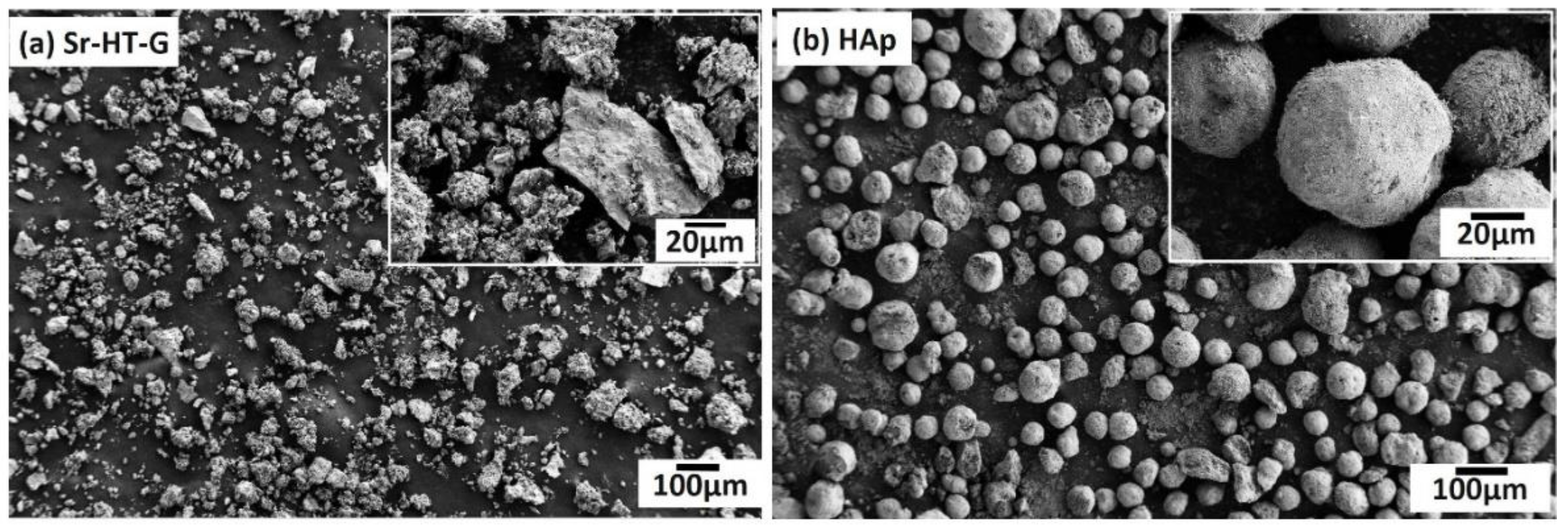
3.1. Feedstock Morphology

Morphologies of Sr–HT–G (after of mixing with PVA, consolidating, grinding and sieving) and HAp powders are indicated in Figure 1a,b, respectively. Sr–HT–G powders were manually ground and sieved so the powders are described as angular and blocky, while HAp powders are spherical-like shape. The morphology of Sr–HT–G powders provide higher ratio of surface area to volume than that of HAp powders, which can lead to a better degree of heating in plasma plumes [29]. HAp may present better flow transportation characteristics than Sr–HT–G because spherical powders are preferable morphology in plasma spray. These HAp particles can easily enter into the center of the plasma plume to be well deposited, while Sr–HT–G powders may not be injected ideally into the plasma flame due to irregular sizes [11,29].

3.2. Coating Surface Analysis

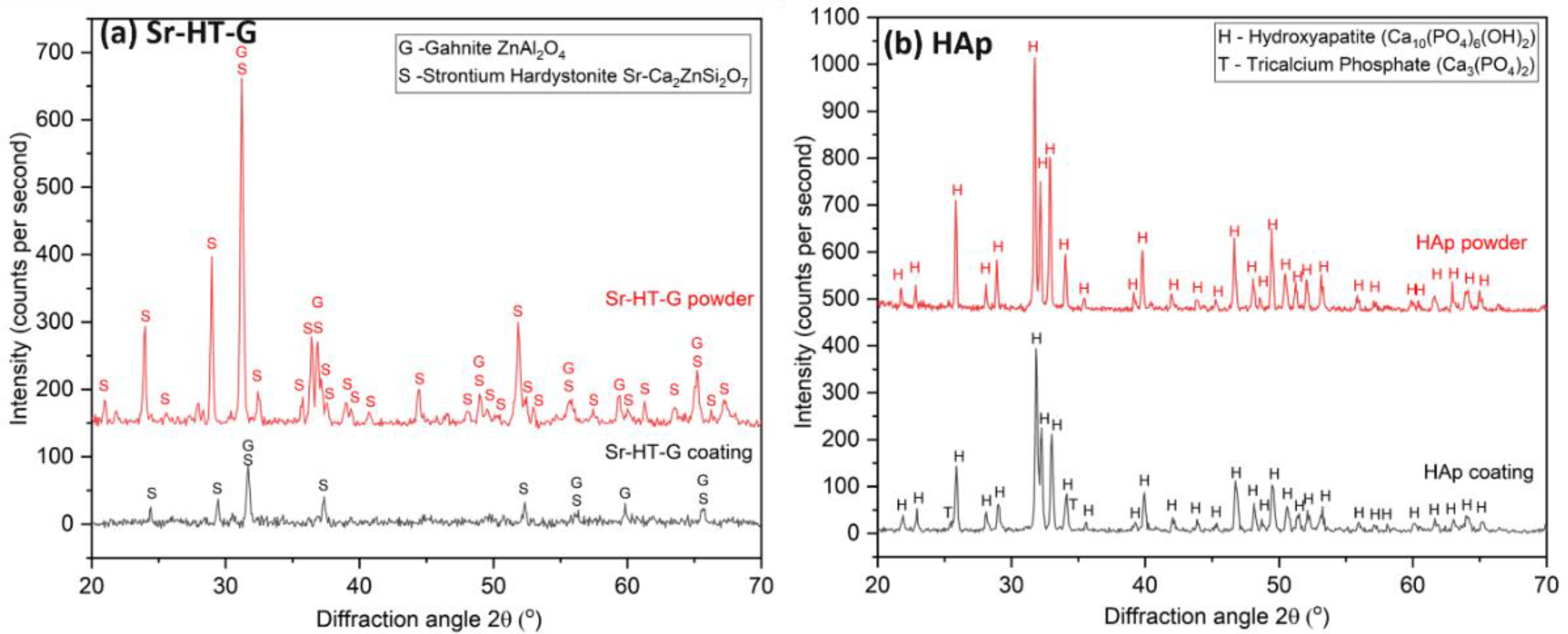
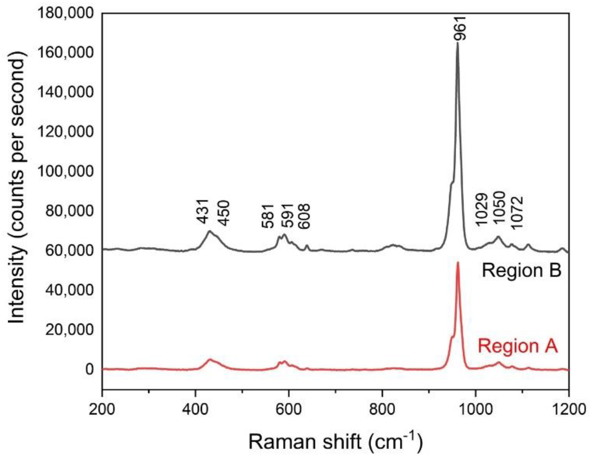
3.2.1. Phase Compositions

Figure 2 presents the XRD results of powders and coatings for Sr–HT–G and HAp. Sr–HT–Ga powders consist of two distinct phases in Figure 2a, which are Sr–HT (PDF 01-072-1603) and gahnite (PDF 01-070-8181). The gahnite phase in starting powders is formed by the reaction between zinc in Sr–HT and alumina during the sintering process at high temperatures to produce powders [22]. Similar to the staring powders, the coating of Sr–HT–G also presents two phases, which are Sr–HT and gahnite. The peaks of Sr–HT–G coating are significantly less sharp and are broaden after the plasma coating, which indicate the reduction in the level of crystallinity. However, there is no new peaks formed in the Sr–HT–G coating, but they are slightly shifted in the peaks of the coating comparing with its powders. The reason for the peak shifts could be the internal or residual stress after coating, which causes the change in lattice parameters. On the other hand, HAp powders present high purity with phase of HAp, but its coating presented the phase of Ca10(PO4)6(OH)2 (PDF 00-064-0738) and a new phase of tricalcium phosphate-TCP (Ca3(PO4)2) (PDF 01-072-7587) in Figure 2b. This new phase TCP was formed by the reaction of HAp in the high temperature region of plasma plume [30].
Both coatings illustrate lower intensity levels or lower crystallinity compared with their starting powders. Significant lower intensity of the peaks in a coating comparing to its starting powder can be seen in the result of Sr–HT–G, of which the level of crystallinity from Equation (1) are 74.6% and 32.7% for powders and the coating, respectively. On the other hand, levels of crystallinity in HAp powders and coating are not significantly different, which are 84.8% and 75.5% for powders and the coating, respectively. The lower crystallinity in the coating is a feature of the plasma process, which feedstock are exposed and heated by a 10,000 °C plasma flame, then rapidly cooled at about 106 degrees per second, where the feedstock do not have enough time to recrystallize [29]. It can be seen that the Sr–HT–G coating presents lower levels of crystallinity than that in the HAp coating. Sr–HT–G is a Ca-Si ceramic with the sorosilicate (Si2O7) group that has a more intricate crystalline structure, so the process of recrystallize will be more complex than that of HAp [31]. In contrast, HAp powders with larger particle sizes are well deposited with a larger quantity in the coating because they are fed into the center of the plasma flame. As the result, a greater amount of bulk crystalline can be found in the coating, which leads to a higher percentage of crystallinity [32].

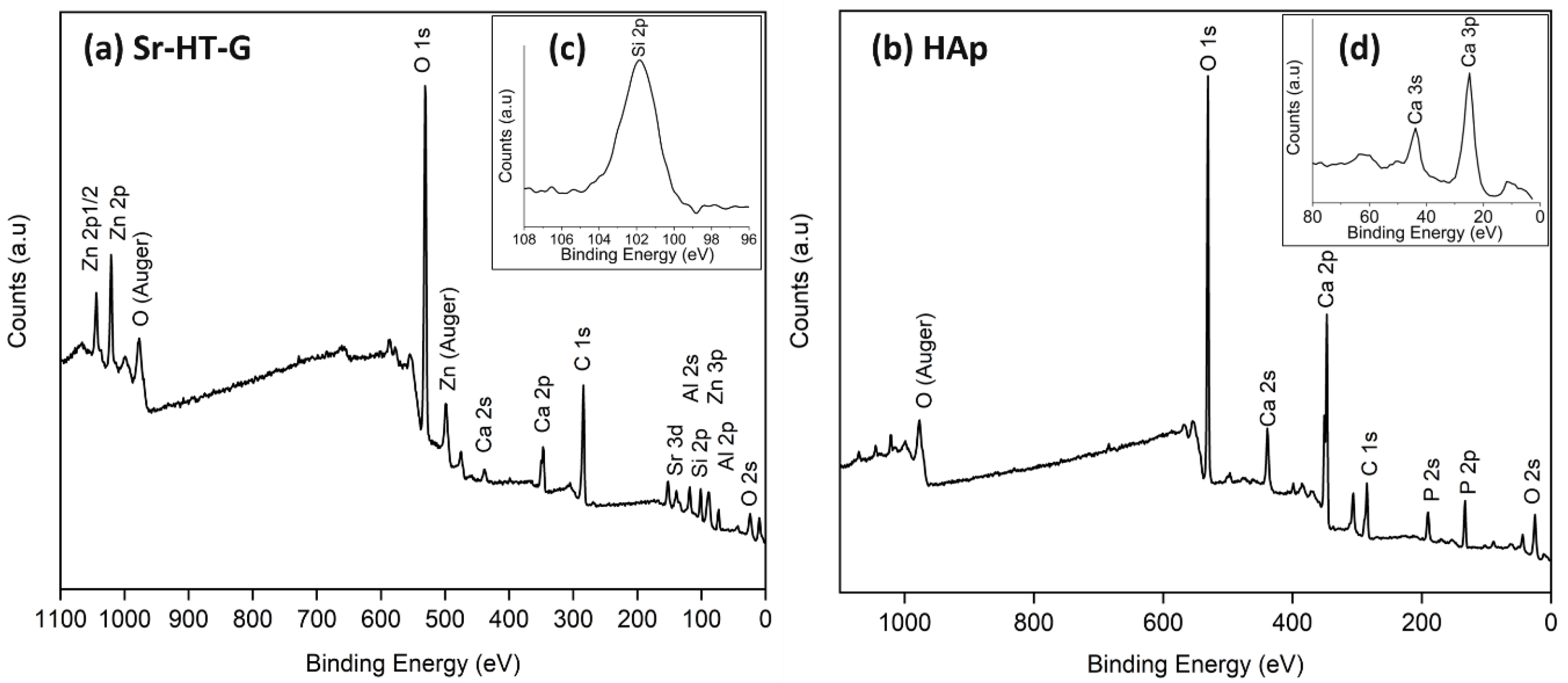
3.2.2. XPS on Coating Surfaces

Figure 3a presents the XPS analysis result of Sr–HT–G coating with the presence of Sr, Ca, Zn, Si, O, Al on the coating surface. Two peaks of Zn in the spectrum are Zn 2p and Zn 2p1/2 at 1022.9 and 1045.9 eV, respectively. Furthermore, the presenting of the peaks Al 2p at 74.0 eV and Al 2s at 119.0 eV together with the peak O 1s at 531.5 eV indicates the formation of ZnAl2O4 on the coating surface [33,34]. In a high-resolution scan presented in Figure 3c, Si presented the peak of Si 2p at 102 eV, which refers to the presence of a silicate group [35]. This silicate group is Si2O7, which is in the structure of Sr–HT. Formation of Sr–HT and gahnite phases are further supported by results from the analysis in XRD. The Sr–HT and gahnite composite ceramic has shown an improvement in biocompatibility and bioactivity, which has been evaluated by its capability in osteoconduction and osteoinduction [36]. Thus, a plasma coating with the present of Sr–HT and gahnite phases will potentially produce good biocompatibility and bioactivity.
Chemical elements on the surface of HAp coating under XPS analysis are shown in Figure 3b. The surface of HAp coating consists of Ca, P, and O as the main elements in its starting powders. The peak of P 2p is 132.8 eV, while the peak of O 1s is 530.8 eV. This result indicates the present of the PO43− group [35], which is in the structure of hydroxyapatite Ca10(PO4)6(OH)2. Calcium has four peaks, which are Ca 2s, Ca 2p, Ca 3s, and Ca 3p. The Ca 2s presents a peak at 438.6 eV, while the Ca 2p consists of a doublet with values of 346.9 and 350.4 eV for Ca 2p3/2 and Ca 2p1/2, respectively. The peaks of Ca 3i and Ca 3p are 44.0 and 25.3 eV that are illustrated in Figure 3d. The results of calcium peaks indicate the formation of Ca3(PO4)2 [37]. These HAp phases have been shown to support the in vitro and in vivo formation of bone.

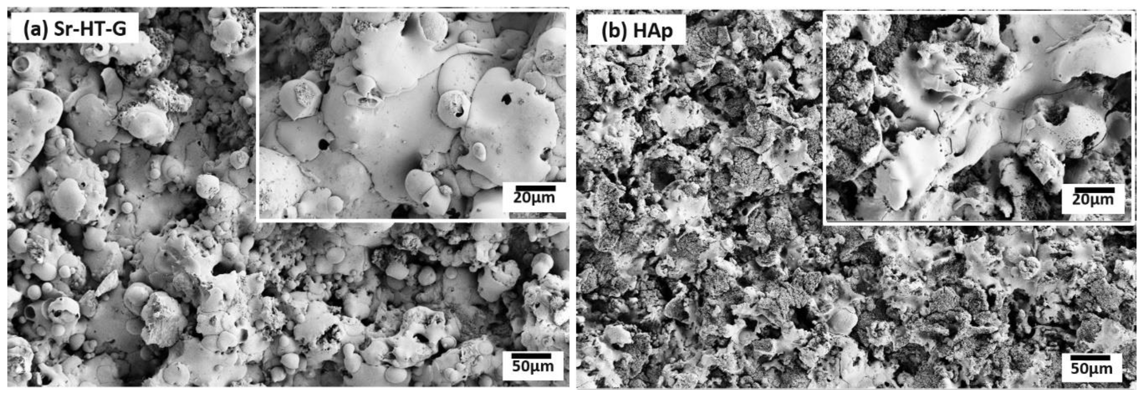
3.2.3. Morphologies of Coating Surfaces

Surfaces of the Sr–HT–G and the HAp coatings are shown in Figure 4a,b, respectively, where both coatings show well-melted splats. However, the Sr–HT–G coating shows more uniform surface morphology with spherical-like splat shapes, while HAp coating presents irregular splats with a big splash at the rims. Furthermore, some fragmentations can be found within splats of the HAp coating, whilst the Sr–HT–G coating shows more consistent structure on the surface with more uniform splats. Under the melting and re-solidify processes in APS, well-melted splats or partially melted particles will spread onto the substrate and form layers of splats [38]. Molten particles of Sr–HT–G show higher spreading ability than the HAp, which could be closely related to its viscosity characteristics and eventually reveals more regular Sr–HT–G splats [39].

3.3. Coating Cross Section Analysis

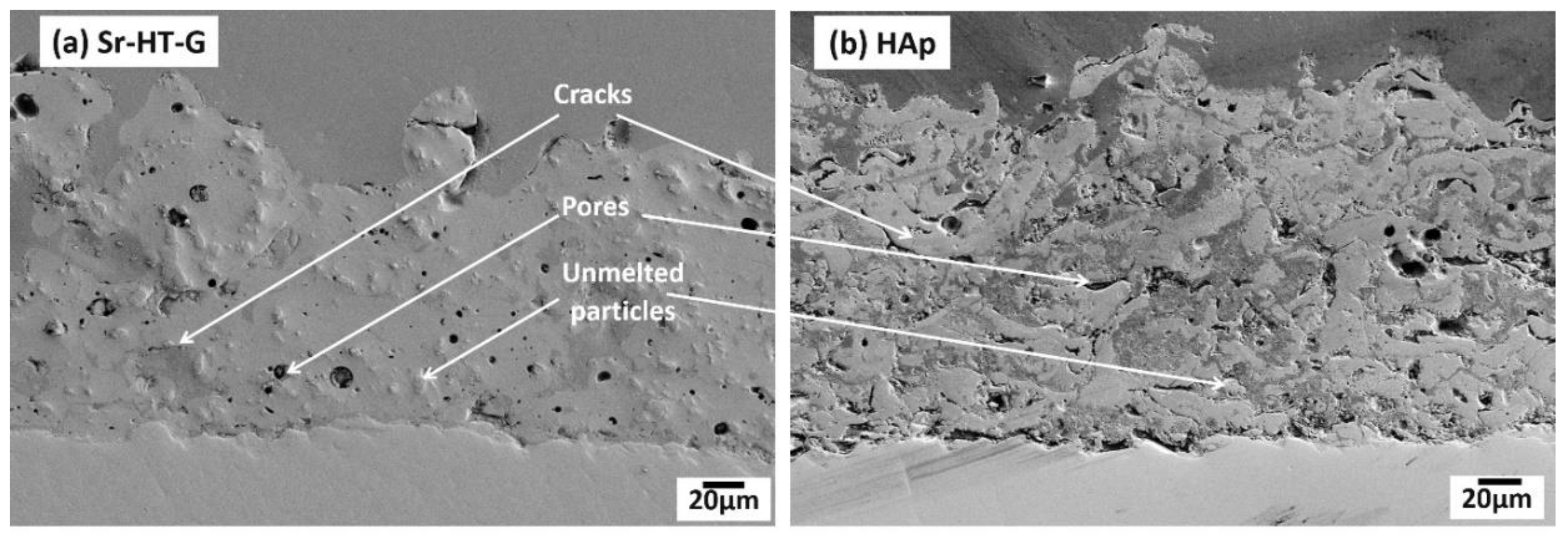
3.3.1. Coating Microstructures

Figure 5 indicates the microstructure of the Sr–HT–G and the HAp coatings at cross sections. Both coatings present features of thermal spray coating including cracks, pores, and unmelted particles [38]. Different phases can be found in the HAp coating as the result of different contrasts, which are shown in bright gray and dark gray. The amorphous phase is easily removed during the polishing process, which causes the height to be lower than the crystalline areas. As the result, the amorphous phase appears to be darker. This observation has been re-confirmed with Raman spectroscopy. Similar results have been presented in the works of Gross et al. [30,40]. However, there is not much difference in contrast of phases in the Sr–HT–G coating as its microstructure presents a similar contrast to the source of ignition during the SEM process. It can be seen that the Sr–HT–G coating has less cracks in microstructure, while the HAp coating presents more cracks. Moreover, due to the reaction of alumina with zinc in Sr–HT, a more uniform structure is formed [36], where the Sr–HT–G coating has a denser structure and a more consistent microstructure compared with the HAp coating. Less pores in the structure of the Sr–HT–G coating could come from the larger distribution of powder sizes, where different sizes of Sr–HT–G splats are likely to fill up the pores in the microstructure during the process of deposition [11]. In addition, the interface of coating-substrate in the Sr–HT–G coating is quite consistent with crack-free features, while the HAp coating shows minor cracks at the coating-substrate interface.

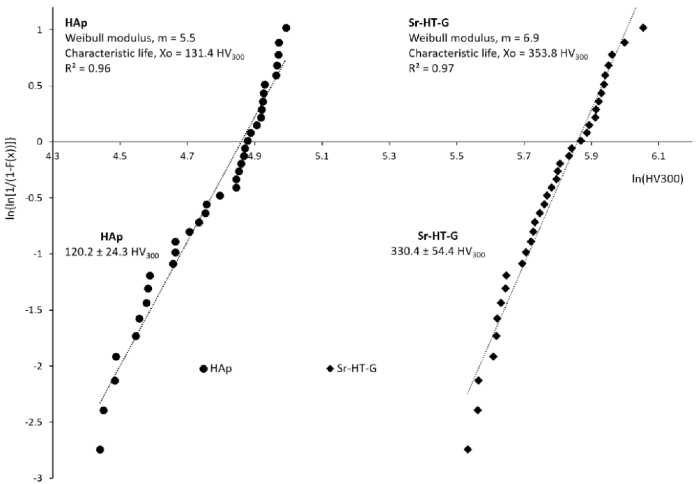
3.3.2. Vickers Microhardness

The results of Vickers microhardness are shown in Figure 6, where the hardness of the Sr–HT–G and the HAp coatings are 330.4 ± 54.4 HV300 and 120.2 ± 24.3 HV300, respectively. Vickers microhardness in the coating of Sr–HT–G is significantly high due to the addition of Zn into the Ca-Si structure [19,21], which is almost triple the hardness of the HAp coating. In addition, the formation of a glass phase between Sr–HT grains and the existence of a strong restraint surrounding the Sr–HT grains from the glass-ceramic phase of gahnite also leads to the improvement in mechanical properties of the Sr–HT–G coating [36]. The coefficient of variant (CoV = standard deviation divided by the mean) of the Sr–HT–G is coating slightly lower than that of the HAp coating, which are 16% and 20%, respectively. The coating of Sr–HT–G has lower CoV values in microhardness because the Sr–HT–G coating possesses a more uniform microstructure compared to those in the HAp coating. The Weibull analysis of microhardness of the Sr–HT–G and HAp coatings are presented in Figure 6, where both coatings present good regression fits with R2 values of 0.97 and 0.96, respectively [41]. The Weibull moduli m, which presents the scattering behavior of results within the distribution [41], show that both the Sr–HT–G and HAp coatings have low values of Weibull modulus but they are the typical values in thermal spray. The Sr–HT–G coating has a slightly higher value of Weibull moduli than the HAp coating, which indicates less variation in the microhardness results in the Sr–HT–G coating.

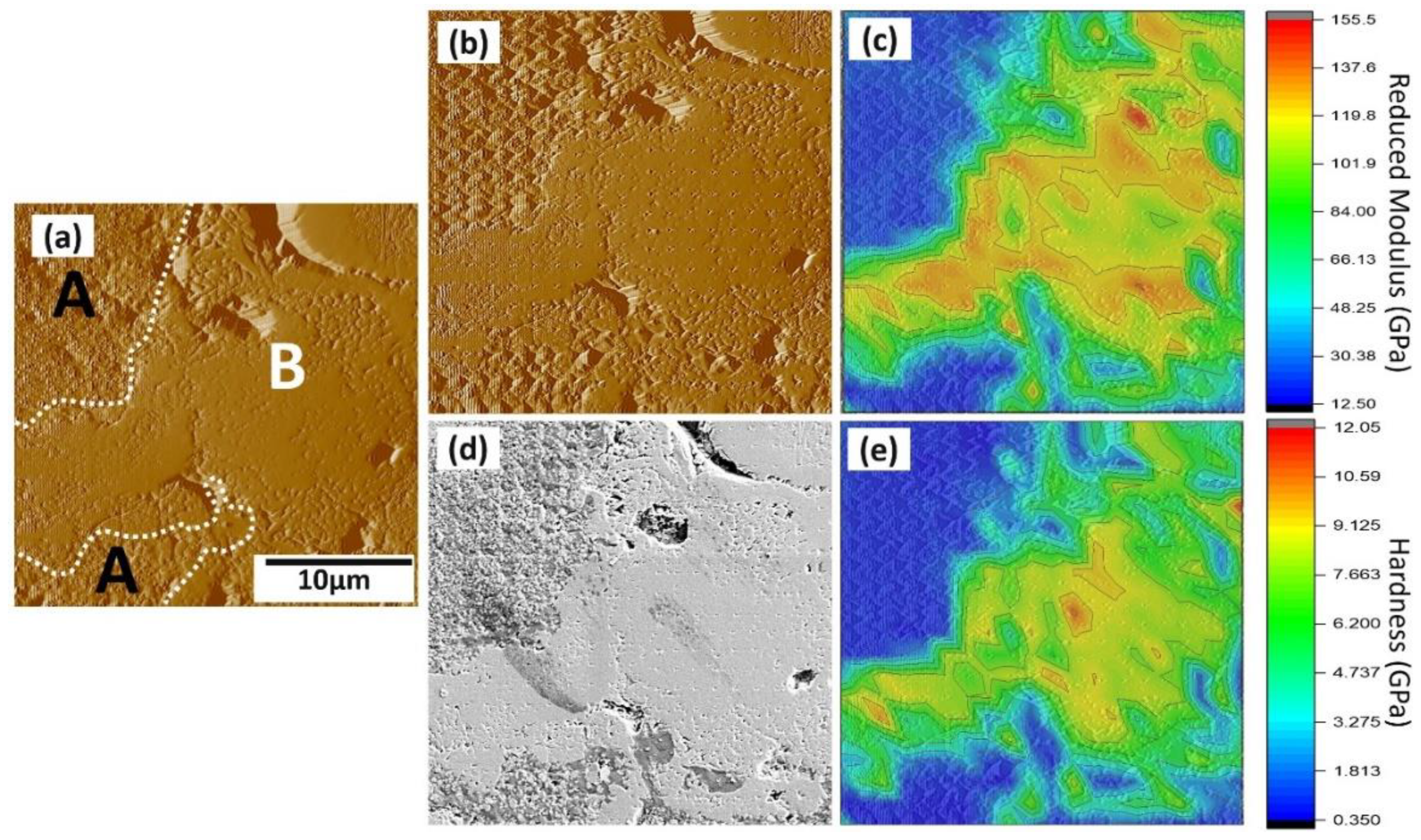
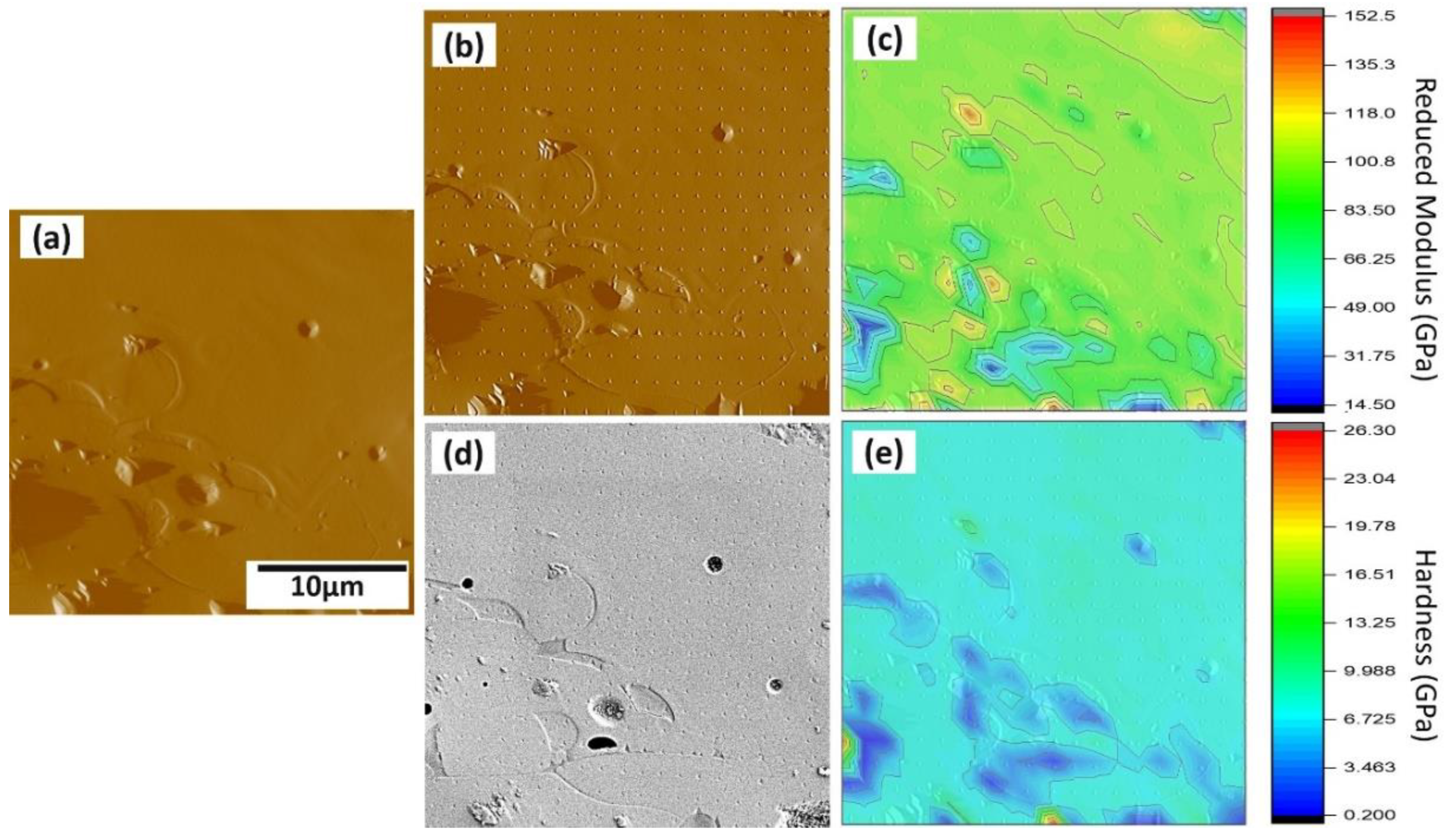
3.3.3. Nanohardness and Elastic Moduli

The cross section of the Sr–HT–G coating shows a uniform structure in the coating, shown in Figure 7a. Figure 7b,d presents corresponding the SPM and SEM images of the same area after performing the nanoindentation. The indentation mapping results of the Sr–HT–G coating are presented by the distributions of elastic moduli and hardness in Figure 7c,e, respectively. The variant in the distributions of nanohardness and elastic moduli depends on the features of the selected area such as element compositions, phase structure, cracks, and pores. Generally, lower hardness and lower elastic moduli can be found in pore and crack areas [42]. Uniform distributions of nanohardness and elastic modulus can be achieved in the Sr–HT–G coating, which indicate the consistent of mechanical properties across the coating. This uniformity could be achieved by the presence of the gahnite phase in the coating that could enhance the mechanical properties across the coating [36].
The distributions of nanohardness and elastic moduli in a selected area from the HAp coating are found in Figure 8. Similar to the testing procedure of the Sr–HT–G coating, Figure 8a presents a selected area that was pre-scanned to capture the features before performing the nanoindentation. After performing the nanoindentation, the surface was captured again via SPM and SEM techniques, which are shown in Figure 8b,d, respectively. The difference in contrast of the SEM image present different phases that have formed, which are named as “A” and “B” regions. The results of elastic moduli and nanohardness of the HAp coating are shown in Figure 8c,e in the form of distribution maps, respectively. The marks of indents in the HAp coating at the “A” area present deeper and larger sizes than those in the “B” area. Raman microspectroscopy was used to analyze the functional groups of the highlighted Region A and B of the HAp coating. It can be seen that both regions have same functional groups as the result of similar positions of Raman peaks in Figure 9. However, sharper peaks with higher intensity can be found in Region B, which indicates the formation of crystalline HAp while Region A presents the formation of an amorphous phase [43]. Similar to the study of J. Wen et al. [44], Region B yielded better mechanical properties, which it showed higher results of nanohardness and elastic moduli than Region A.
This indicates there is less uniformity of coating phases in the HAp coating when comparing with the Sr–HT–G coating. As the result, both nanohardness and elastic moduli showed high variants in distribution of values across the HAp coating. The average values of elastic moduli and nanohardness of the Sr–HT–G coating were 93.0 ± 16.6 and 7.2 ± 2.1 GPa, respectively. On the other hand, lower results of both elastic modulus and nanohardness can be found in the HAp coating, which the average values were 77.6 ± 41.5 and 4.4 ± 3.2 GPa, respectively. The average results of both nanohardness and elastic moduli in the Sr–HT–G coating showed significantly better results than that of the HAp coating, which were in accordance with the results in the Vickers microhardness tests. Furthermore, the Sr–HT–G coating presented lower values of CoV in both hardness and elastic moduli with 17.8% and 29.2%, respectively, while these values of hardness and elastic moduli in the HAp coating were higher at 53.4% and 72.7% due to the lack of uniform phases.

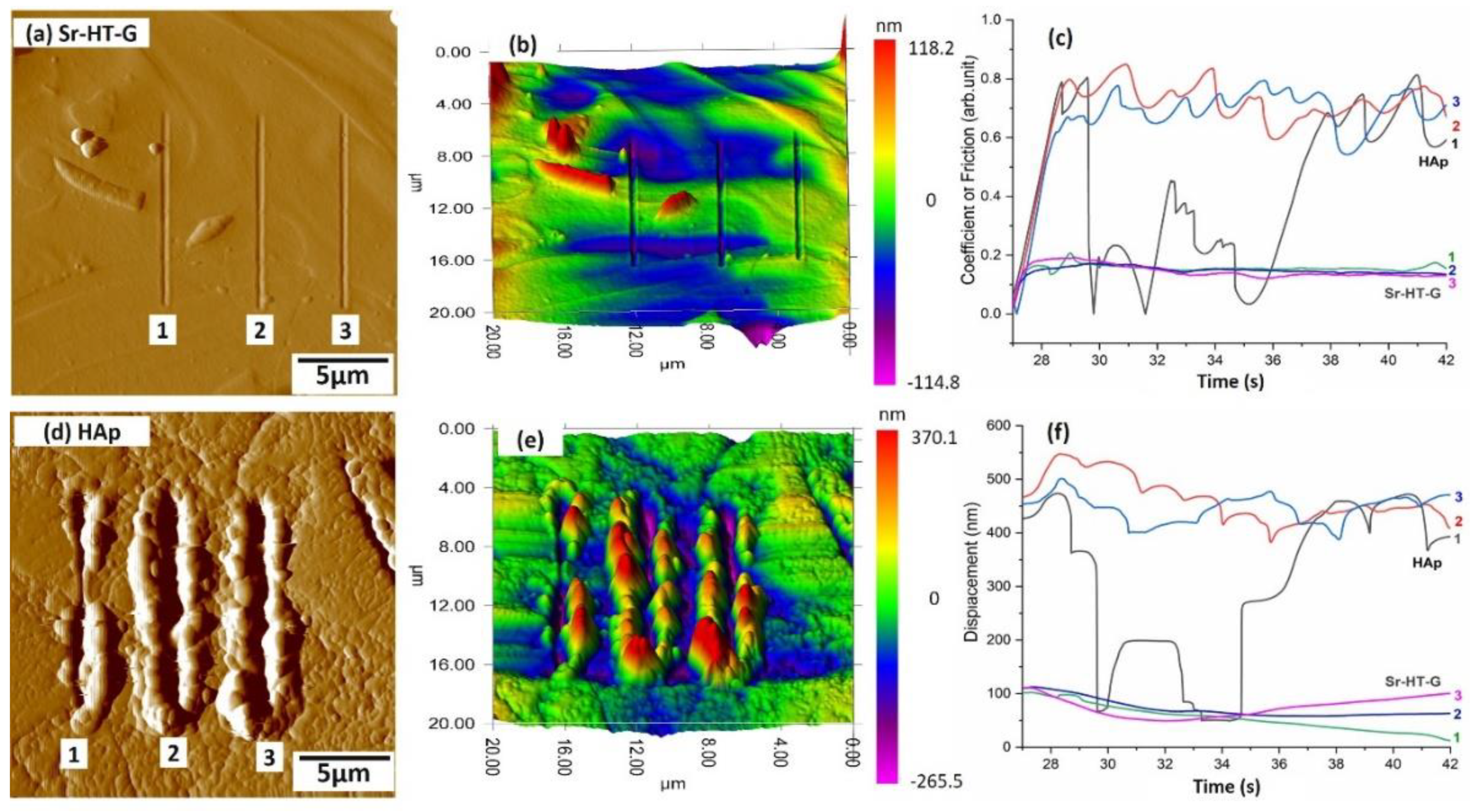
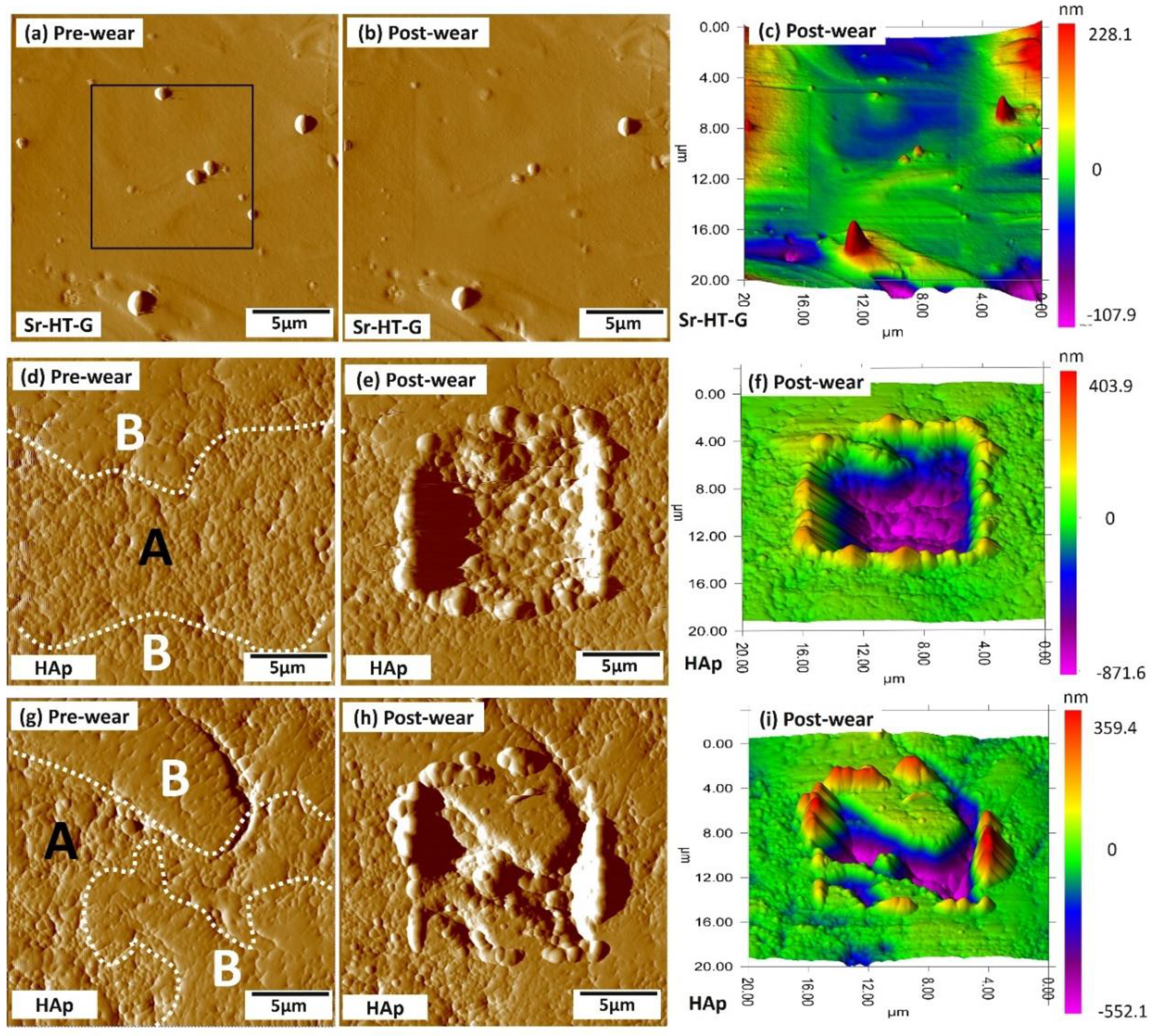
3.3.4. Nanoscratch and Nanoscanning Wear Performance

Results of nanoscratch tests under the load of 1000 µN are presented in Figure 10, where Figure 10a,d shows the surfaces of the selected areas after the scratching of Sr–HT–G and HAp coatings, respectively. It can be seen that the Sr–HT–G coating depicts tearing behavior only with shallow depths of penetration, while deeper and more plastic flow across the edge of the scratch direction can be found in the HAp coating. The 3D maps in Figure 10b,e render more details of the behavior of these coatings under scratch tests. The HAp coating experienced more plastic deformation with large pileup of materials that represents ploughing behavior under the scratch test.
Figure 10c,f reveals the coefficient of friction (CoF) and depth of the scratch (displacement) of the Sr–HT–G and the HAp coatings, respectively, which show the details of Scratch 1, 2, and 3 from the Figure 10a,c. In the nanoscratch test, the actual applied load started from the 27th second to the 42nd second, while other times for loading and unloading periods are not considered. From the results of the nanoscratch tests, CoFs and displacements of the Sr–HT–G coating show high consistency with low values of CoFs and low penetration depths in all the scratches. On the other hand, CoF values and displacements in the HAp coating fluctuate continuously, i.e., values of CoF and displacement significantly decreased from 29.5 to 35 s in the scratches due to higher scratch resistance in this region of the HAp coating. This result could have originated from the significant difference in mechanical properties of different phases in the HAp coating, which has a similar trend with the distribution of hardness and elastic moduli.
The average depths of scratch are 60.9 ± 9.7 nm (CoV = 16%) and 245.0 ± 150.4 nm (CoV = 61%) for the Sr–HT–G and the HAp coatings, respectively. Lower scratch depth with less removal of materials in the Sr–HT–G coating indicate that the Sr–HT–G coating is more resistant to scratches. Furthermore, the average CoF of the Sr–HT–G coating is 0.14 ± 0.02 (CoV = 14%), which is much lower than the average CoF in the HAp coating, 0.69 ± 0.14 (CoV = 20%). Similar to the analysis in the nanoindentation, the lower result of CoV in the scratch test shows the coating microstructure of the Sr–HT–G coating presents more uniform features than the HAp coating. This results in the Sr–HT–G coating shows better scratch resistance than the HAp coating.
The wear behavior of the Sr–HT–G and the HAp coating under the applied load of 1000 μN are presented in Figure 11, in which the pre-wear test, and post-wear test images were evaluated. The black square areas indicate the regions that were selected to perform nanowear tests. The surface before performing wear tests are presented in Figure 11a,d,g; while Figure 11b,e,h and Figure 11c,f,i illustrate the surface after the wear test of SPM images and their 3D views, respectively. Similar to the result from nanoindentation and nanoscratch tests, the Sr–HT–G coating presents uniform distribution with consistent results of wear volume in Figure 11b,c. On the other hand, the HAp coating reveals more variance of wear behavior due to a significant difference in the region of “A” and “B” as amorphous and crystalline regions, respectively, in Figure 11e,h. It can be seen that amorphous areas present less wear resistance than crystalline areas, showing similar trends in nanoindentation and nanoscratch tests. The wear volume for Sr–HT–G and HAp coatings are 0.11 ± 0.03 and 5.52 ± 2.90 µm3, respectively. This enhanced mechanical properties of the Sr–HT–G coating was achieved by doping zinc into a Ca-Si ceramic together with the formation of gahnite in the structure [19,36]. This result indicates that the Sr–HT–G coating possesses superior wear resistance than the HAp coating.

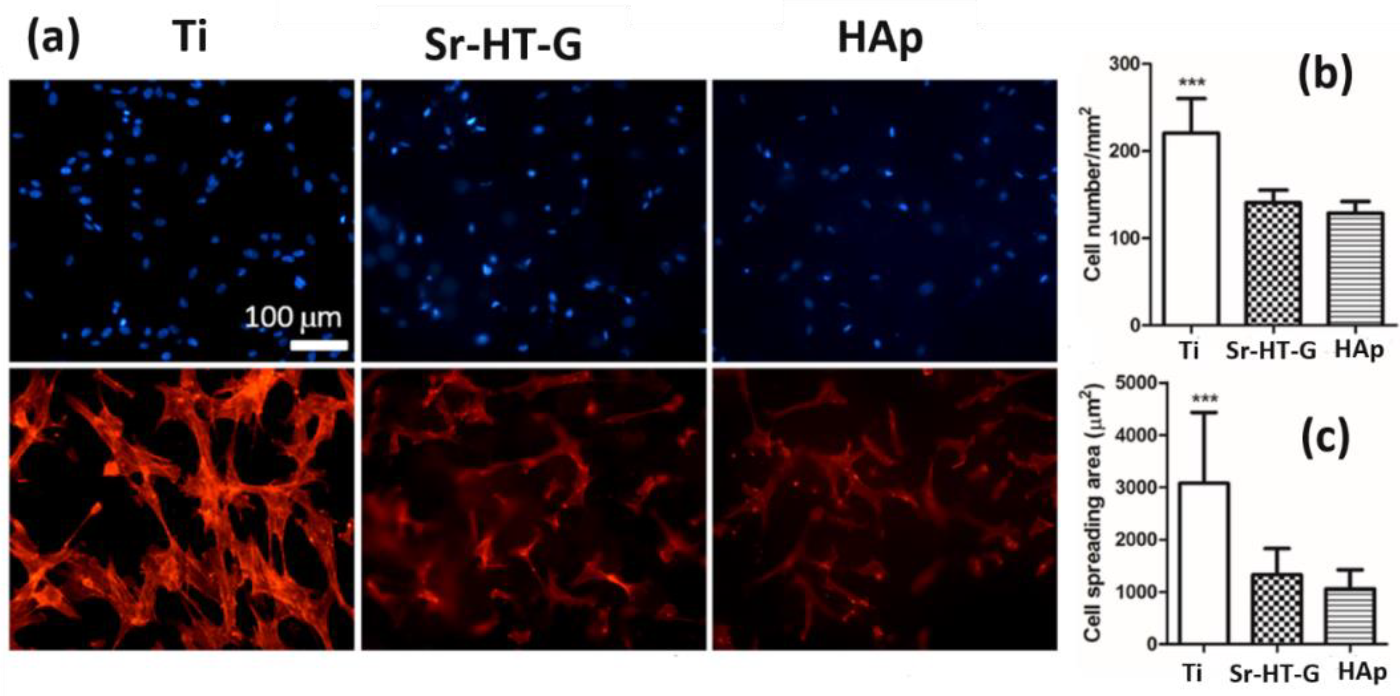
3.4. Results of Stem Cell Culture

After cell culture for 24 h, BMSC adhered on all the substrates indicating a good biocompatibility, which can be seen in Figure 12a. Cell density on Ti substrates was relatively higher than samples of the Sr–HT–G coating and the HAp coating in Figure 12b. In addition, BMSCs have a relatively larger cell spread on Ti substrates than that of the Sr–HT–G and HAp coatings, which can be seen in Figure 12c. This strong cell attachment on the Ti substrate is related to the differences in surface roughness profiles; both coatings had similar and higher surface roughness than the Ti. The surface roughness (Ra) of the Sr–HT–G coating and the HAp coating were 13.7 ± 0.76 and 10.2 ± 0.7 µm, respectively; while the roughness of the as-receive Ti was about 0.1 µm. Nonetheless, the results indicate both coatings have good biocompatibility for BMSCs, in which the Sr–HT–G coating presented slightly higher cell density and spreading area of cell attachment compared to the HAp coating.

4. Conclusions

The deposition of Sr–HT–G powders onto Ti–6Al–4V as a novel coating via an atmospheric plasma spray technique has demonstrated significant improvement in mechanical properties compared with the current commercial relevant hydroxyapatite coating. The Sr–HT–G coating showed more uniform microstructures with consistent distributions of hardness, elastic moduli, compared to the HAp coating. The as sprayed Sr–HT–G coating presented phases of Sr-HT and gahnite without formation of new phases. Vickers microhardness of the Sr–HT–G coating was significantly higher than results from the HAp coating; 330.4 ± 54.4 and 120.2 ± 24.3 HV300, respectively. Nanoindentation tests revealed consistent distributions of nanohardness and elastic moduli in the Sr–HT–G coating with the average values of 93.0 ± 16.6 and 7.2 ± 2.1 GPa for hardness and elastic moduli, respectively. On the contrary, the HAp coating showed lower and high variation in the distribution of hardness and elastic moduli, especially between the distinct areas of crystalline and amorphous phases. The nanohardness and elastic moduli of the HAp coating were 77.6 ± 41.5 and 4.4 ± 3.2 GPa, respectively. The Sr–HT–G coating also showed better resistance to scratch and wear compared to the HAp coating under the same tests. In addition, the Sr–HT–G coating presented slightly higher density and spreading area of cell attachment in contrast to the HAp coating, indicating that the Sr–HT–G coatings possess good biocompatibility with good attachment of bone marrow mesenchymal stem cells. This study indicates that atmospheric plasma sprayed Sr–HT–G can be a viable approach for orthopaedic implants.

Author Contributions

Conceptualization, A.S., H.Z., C.C.B. and A.S.M.A.; methodology, D.Q.P., A.S.M.A. and C.C.B.; software, D.Q.P. and Y.-P.W.; validation, C.C.B., A.S.M.A. and H.Z.; formal analysis, D.Q.P.; investigation, D.Q.P.; resources, A.S., D.Q.P. and A.S.M.A.; data curation, D.Q.P., A.S.M.A.; writing—original draft preparation, D.Q.P., P.-Y.W.; writing—review and editing, D.Q.P., A.S.M.A., C.C.B. and P.-Y.W.; visualization, D.Q.P., A.S.M.A.; supervision, A.S.M.A., C.C.B., H.Z.; project administration, A.S.M.A., C.C.B.; funding acquisition, A.S., H.Z. and C.C.B.

Funding

This research is funded by the Centre for Innovative BioEngineering under the Industrial Transformation Training Centre (ITTC) scheme via the Australian Research Council (ARC) Award IC170100022. PYW thanks the support from the National Key Research and Development Program of China (2018YFC1105201), the National Natural Science Foundation of China, and the International cooperative research project of Shenzhen collaborative innovation program (20180921173048123).

Acknowledgments

The authors also would like to thank Deming Zhu for his assistance in operating the XPS and Andrew Moore for expert assistance in the preparation of samples. We deeply appreciate Ping Du from SIAT who performed the biocompatibility test.

Conflicts of Interest

The authors declare no conflict of interest.

References

  1. Wu, C.; Chang, J. A review of bioactive silicate ceramics. Biomed. Mater. 2013, 8, 032001. [Google Scholar] [CrossRef] [PubMed]
  2. Park, J.B.; Bronzino, J.D. Biomaterials: Principles and Applications; CRC Press: Boca Raton, FL, USA, 2002. [Google Scholar] [CrossRef]
  3. Dorozhkin, S.V.; Epple, M. Biological and medical significance of calcium phosphates. Angew. Chem. Int. Ed. 2002, 41, 3130–3146. [Google Scholar] [CrossRef]
  4. Sun, L.; Berndt, C.C.; Gross, K.A.; Kucuk, A. Material fundamentals and clinical performance of plasma-sprayed hydroxyapatite coatings: A review. J. Biomed. Mater. Res. 2001, 58, 570–592. [Google Scholar] [CrossRef] [PubMed]
  5. Hench, L.L. Biomaterials: A forecast for the future. Biomaterials 1998, 19, 1419–1423. [Google Scholar] [CrossRef]
  6. Berndt, C.; Haddad, G.; Farmer, A.; Gross, K.A. Thermal spraying for bioceramic applications. Mater. Forum. 1990, 14, 161–173. [Google Scholar]
  7. Dorozhkin, S.V. Bioceramics of calcium orthophosphates. Biomaterials 2010, 31, 1465–1485. [Google Scholar] [CrossRef]
  8. Yao, H.-L.; Zou, Y.-L.; Bai, X.-B.; Wang, H.-T.; Ji, G.-C.; Chen, Q.-Y. Microstructures, mechanical properties and electrochemical behaviors of nano-structured HA/Ti composite coatings deposited by high-velocity suspension flame spray (HVSFS). Ceram. Int. 2018, 44, 13024–13030. [Google Scholar] [CrossRef]
  9. Chen, X.; Zhang, B.; Gong, Y.; Zhou, P.; Li, H. Mechanical properties of nanodiamond-reinforced hydroxyapatite composite coatings deposited by suspension plasma spraying. Appl. Surf. Sci. 2018, 439, 60–65. [Google Scholar] [CrossRef]
  10. Rauch, J.; Bolelli, G.; Killinger, A.; Gadow, R.; Cannillo, V.; Lusvarghi, L. Advances in high velocity suspension flame spraying (HVSFS). Surf. Coat. Technol. 2009, 203, 2131–2138. [Google Scholar] [CrossRef]
  11. Tucker, R.C., Jr. ASM Handbook, Volume 05A—Thermal Spray Technology; ASM International: Materials Park, OH, USA, 2013. [Google Scholar] [CrossRef]
  12. Sun, L. Thermal spray coatings on orthopedic devices: When and how the FDA reviews your coatings. J. Therm. Spray Technol. 2018, 27, 1280–1290. [Google Scholar] [CrossRef]
  13. Schwarz, K. A bound form of silicon in glycosaminoglycans and polyuronides. Proc. Natl. Acad. Sci. USA 1973, 70, 1608–1612. [Google Scholar] [CrossRef] [PubMed]
  14. Carlisle, E.M. Silicon: A possible factor in bone calcification. Science 1970, 167, 279. [Google Scholar] [CrossRef] [PubMed]
  15. Hench, L.L. Bioceramics: From concept to clinic. J. Am. Ceram. Soc. 1991, 74, 1487–1510. [Google Scholar] [CrossRef]
  16. Abe, Y.; Kokubo, T.; Yamamuro, T. Apatite coating on ceramics, metals and polymers utilizing a biological process. J. Mater. Sci. Mater. Med. 1990, 1, 233–238. [Google Scholar] [CrossRef]
  17. Liu, X.; Tao, S.; Ding, C. Bioactivity of plasma sprayed dicalcium silicate coatings. Biomaterials 2002, 23, 963–968. [Google Scholar] [CrossRef]
  18. Ni, S.; Chang, J.; Chou, L.; Zhai, W. Comparison of osteoblast-like cell responses to calcium silicate and tricalcium phosphate ceramics in vitro. J. Biomed. Mater. Res. Part B Appl. Biomater. 2007, 80, 174–183. [Google Scholar] [CrossRef]
  19. Zreiqat, H.; Ramaswamy, Y.; Wu, C.; Paschalidis, A.; Lu, Z.; James, B.; Birke, O.; McDonald, M.; Little, D.; Dunstan, C.R. The incorporation of strontium and zinc into a calcium–silicon ceramic for bone tissue engineering. Biomaterials 2010, 31, 3175–3184. [Google Scholar] [CrossRef]
  20. Iimori, Y.; Kameshima, Y.; Okada, K.; Hayashi, S. Comparative study of apatite formation on CaSiO3 ceramics in simulated body fluids with different carbonate concentrations. J. Mater. Sci. Mater. Med. 2005, 16, 73–79. [Google Scholar] [CrossRef]
  21. Wu, C.; Chang, J.; Zhai, W. A novel hardystonite bioceramic: Preparation and characteristics. Ceram. Int. 2005, 31, 27–31. [Google Scholar] [CrossRef]
  22. Roohani-Esfahani, S.I.; Dunstan, C.R.; Li, J.J.; Lu, Z.; Davies, B.; Pearce, S.; Field, J.; Williams, R.; Zreiqat, H. Unique microstructural design of ceramic scaffolds for bone regeneration under load. Acta Biomater. 2013, 9, 7014–7024. [Google Scholar] [CrossRef]
  23. Wang, G.; Roohani-Esfahani, S.-I.; Zhang, W.; Lv, K.; Yang, G.; Ding, X.; Zou, D.; Cui, D.; Zreiqat, H.; Jiang, X. Effects of Sr-HT-Gahnite on osteogenesis and angiogenesis by adipose derived stem cells for critical-sized calvarial defect repair. Sci. Rep. 2017, 7, 41135. [Google Scholar] [CrossRef] [PubMed]
  24. Li, J.J.; Dunstan, C.R.; Entezari, A.; Li, Q.; Steck, R.; Saifzadeh, S.; Sadeghpour, A.; Field, J.R.; Akey, A.; Vielreicher, M.; et al. A novel bone substitute with high bioactivity, strength, and porosity for repairing large and load-bearing bone defects. Adv. Healthc. Mater. 2019, 8, e1801298. [Google Scholar] [CrossRef] [PubMed]
  25. Sun, L.; Berndt, C.C.; Grey, C.P. Phase, structural and microstructural investigations of plasma sprayed hydroxyapatite coatings. Mater. Sci. Eng. A 2003, 360, 70–84. [Google Scholar] [CrossRef]
  26. ASTM-E1920-03. Standard Guide for Metallographic Preparation of Thermal Sprayed Coatings; ASTM International: West Conshohocken, PA, USA, 2014. [Google Scholar]
  27. Pham, D.Q.; Berndt, C.C.; Gbureck, U.; Zreiqat, H.; Truong, V.K.; Ang, A.S.M. Mechanical and chemical properties of Baghdadite coatings manufactured by atmospheric plasma spraying. Surf. Coat. Technol. 2019, 378, 124945. [Google Scholar] [CrossRef]
  28. Oliver, W.C.; Pharr, G.M. An improved technique for determining hardness and elastic modulus using load and displacement sensing indentation experiments. J. Mater. Res. 1992, 7, 1564–1583. [Google Scholar] [CrossRef]
  29. Berndt, C.C.; Hasan, F.; Tietz, U.; Schmitz, K.P. A review of hydroxyapatite coatings manufactured by thermal spray. In Advances in Calcium Phosphate Biomaterials; Ben-Nissan, B., Ed.; Springer: Berlin/Heidelberg, Germany, 2014; pp. 267–329. [Google Scholar] [CrossRef]
  30. Gross, K.A.; Berndt, C.C.; Herman, H. Amorphous phase formation in plasma-sprayed hydroxyapatite coatings. J. Biomed. Mater. Res. 1998, 39, 407–414. [Google Scholar] [CrossRef]
  31. Najafinezhad, A.; Abdellahi, M.; Ghayour, H.; Soheily, A.; Chami, A.; Khandan, A. A comparative study on the synthesis mechanism, bioactivity and mechanical properties of three silicate bioceramics. Mater. Sci. Eng. C 2017, 72, 259–267. [Google Scholar] [CrossRef]
  32. Levingstone, T.J.; Ardhaoui, M.; Benyounis, K.; Looney, L.; Stokes, J.T. Plasma sprayed hydroxyapatite coatings: Understanding process relationships using design of experiment analysis. Surf. Coat. Technol. 2015, 283, 29–36. [Google Scholar] [CrossRef]
  33. Strohmeier, B.R. Zinc Aluminate (ZnAl2O4) by XPS. Surf. Sci. Spectra 1994, 3, 128–134. [Google Scholar] [CrossRef]
  34. Strohmeier, B.R.; Hercules, D.M. Surface spectroscopic characterization of the interaction between zinc ions and γ-alumina. J. Catal. 1984, 86, 266–279. [Google Scholar] [CrossRef]
  35. Moulder, J.F.; Stickle, W.F.; Sobol, P.E. Handbook of X-ray Photoelectron Spectroscopy: A Reference Book of Standard Spectra for Identification and Interpretation of XPS Data; Physical Electronics, Inc.: Eden Prairie, MN, USA, 1995. [Google Scholar]
  36. Zreiqat, H.; Roohani-Esfahani, S.-I.; Dunstan, C.; Li, J.J. Biocompatible Material and Uses Thereof. U.S. Patent No. US 9,220,806 B2, 29 December 2015. [Google Scholar]
  37. Demri, B.; Muster, D. XPS study of some calcium compounds. J. Mater. Process. Technol. 1995, 55, 311–314. [Google Scholar] [CrossRef]
  38. Ang, A.S.M.; Berndt, C.C. A review of testing methods for thermal spray coatings. Int. Mater. Rev. 2014, 59, 179–223. [Google Scholar] [CrossRef]
  39. Madejski, J. Solidification of droplets on a cold surface. Int. J. Heat Mass Transf. 1976, 19, 1009–1013. [Google Scholar] [CrossRef]
  40. Gross, K.A.; Saber-Samandari, S.; Heemann, K.S. Evaluation of commercial implants with nanoindentation defines future development needs for hydroxyapatite coatings. J. Biomed. Mater. Res. Part B Appl. Biomater. 2010, 93, 1–8. [Google Scholar] [CrossRef]
  41. Lin, C.K.; Berndt, C.C. Statistical analysis of microhardness variations in thermal spray coatings. J. Mater. Sci. 1995, 30, 111–117. [Google Scholar] [CrossRef]
  42. Deram, V.; Minichiello, C.; Vannier, R.N.; Le Maguer, A.; Pawlowski, L.; Murano, D. Microstructural characterizations of plasma sprayed hydroxyapatite coatings. Surf. Coat. Technol. 2003, 166, 153–159. [Google Scholar] [CrossRef]
  43. De Grauw, C.; de Bruijn, J.; Otto, C.; Greve, J. Investigation of bone and calcium phosphate coatings and crystallinity determination using Raman microspectroscopy. Cells Mater. 1996, 6, 6. [Google Scholar]
  44. Wen, J.; Leng, Y.; Chen, J.; Zhang, C. Chemical gradient in plasma-sprayed HA coatings. Biomaterials 2000, 21, 1339–1343. [Google Scholar] [CrossRef]
Figure 1. Feedstock morphology of strontium–hardystonite–gahnite (Sr–HT–G) (a) and hydroxyapatite (HAp) (b).
Coatings 09 00759 g001
Figure 2. XRD results of Sr–HT–G powder and coating (a) and HAp powder and coating (b).
Coatings 09 00759 g002
Figure 3. XPS analysis of Sr–HT–G coating (a) and HAp coating (b). The peaks of Si 2p (c), Ca 3i and Ca 3p (d).
Coatings 09 00759 g003
Figure 4. SEM of coating surfaces of Sr–HT–G (a) and HAp (b).
Coatings 09 00759 g004
Figure 5. Microstructure of Sr-HT-G (a) and HAp (b) on coating cross section.
Coatings 09 00759 g005
Figure 6. Weibull regression analysis of the Vickers hardness test of HAp and Sr–HT–G coatings.
Coatings 09 00759 g006
Figure 7. Results of the nanoindentation test of the Sr–HT–G coating. (a) The SPM image of surface before applying the indents; (b) and (d) the SPM and SEM image of surface after applying the indents; (c) and (e) property map of reduced modulus and hardness of the coating.
Coatings 09 00759 g007
Figure 8. Results of the nanoindentation test of the HAp coating. (a) The SPM image of surface before applying the indents; (b) and (d) the SPM and SEM image of surface after applying the indents; (c) and (e) property map of reduced modulus and hardness of the coating.
Coatings 09 00759 g008
Figure 9. Raman microspectroscopy of the regions in the HAp coating.
Coatings 09 00759 g009
Figure 10. Nanoscratch test results of the Sr–HT–G coating (a,b); and the HAp coating (d,e); friction coefficient (c); and normal displacement (f).
Coatings 09 00759 g010
Figure 11. Nanowear test results of the Sr–HT–G coating (ac) and the HAp coating (di).
Coatings 09 00759 g011
Figure 12. Biocompatibility tests of different substrates using bone marrow stem cells. (a) BMSC morphology on Ti, Sr–HT–G, and HAp surfaces. Cell nucleus (blue) and F-actin (red) were stained. (b) Cell density and (c) spreading area on various substrates. ** p < 0.01 and *** p < 0.001 compared to Sr–HT–G and HAp surfaces.
Coatings 09 00759 g012
Table 1. Setup parameters for plasma coating of Sr–HT–G and HAp powders.
ParametersValue
Power (kW)21
Primary gas flow, Ar (slpm)30
Secondary gas flow, H2 (slpm)5
Powder carrier gas flow, Ar (slpm)9
Number of torch passes5
Stand-off distance (mm)90

