Article

Piezoresistive Characteristics of Nylon Thread Resistive Memories for Wearable Strain Sensors

Department of Electronic Engineering, Cheng Shiu University, Kaohsiung 833, Taiwan
Coatings 2019, 9(10), 623; https://doi.org/10.3390/coatings9100623
Submission received: 30 August 2019 / Revised: 23 September 2019 / Accepted: 27 September 2019 / Published: 28 September 2019
(This article belongs to the Section Surface Characterization, Deposition and Modification)

Abstract

:
A nylon thread (NT) resistive memory is fabricated by performing a simple dip-and-dry solution process using graphene–poly(3,4-ethylenedioxythiophene):poly(4-styrenesulfonate) (PEDOT:PSS) conductive ink. The piezoresistive characteristics of the NT resistive memory are further evaluated for wearable strain sensors. While a stretching strain (ε) is applied to the NT resistive memory, the relative resistance change of low-resistance state (LRS) is found to be higher than that of high-resistance state (HRS). This result implies that the contribution of the local overlapping interconnection change in graphene and PEDOT:PSS materials to the LRS resistance change is greater than that to the HRS resistance change. In addition, through many cycles of repeatedly stretching and releasing the LRS of the NT resistive memory at a fixed ε = 7.1%, a gauge factor of approximately 22 is measured and achieved for a highly sensitive and durable strain sensor. Finally, the actual integration of the NT resistive memory into textiles can provide resistive memory and piezoresistive sensor applications simultaneously for wearable electronic textiles.

1. Introduction

The integration of electronic components into textiles, also called as electronic textiles (e-textiles), can provide an ideal platform to develop emerging wearable e-textiles [1]. Some textile-based electronic components such as sensors [2], transistors [3], and memories [4] have been reported. The conductive polymer poly(3,4-ethylenedioxythiophene):poly(4-styrenesulfonate) (PEDOT:PSS) has been found to be quite adequate for manufacturing wearable e-textiles, because of its low-temperature solution process, low cost, and easy fabrication [3,4,5,6,7,8]. In addition, the textile-based resistive memory using the conductive polymer PEDOT:PSS has been proposed and demonstrated to have typical write-once-read-many-times (WORM) characteristics [4]. For wearable e-textile applications, the textile-based resistive memory that experiences mechanical deformation during assembly and daily wear still remains a challenge and has to be further discussed. The gauge factor (GF) can be used to characterize the piezoresistive properties of the wearable e-textiles. However, Wallace et al. [8] reported that the textile-based strain sensor using the same conductive polymer PEDOT:PSS has a low GF of approximately 1. To improve the piezoresistive characteristics of the strain sensor, Ramaprabhu et al. [9] proposed the use of the graphene–polymer composites to enhance the GF. Recently, Zhu et al. presented a review regarding some wearable strain sensors with high sensitivity using graphene-based or PEDOT:PSS-based composites [10].
This study, therefore, employs graphene–PEDOT:PSS conductive ink to fabricate a nylon thread (NT) resistive memory by performing a simple dip-and-dry solution process. The simple dip-and-dry solution process, which is similar to the dyeing process used in the textile industry, is widely believed to be one of the most promising ways to develop wearable e-textiles [11]. Furthermore, the GF is defined as the ratio of the relative resistance change to stretching strain (ε) for the NT resistive memory. The piezoresistive responses of the NT resistive memory are evaluated and further investigated for wearable strain sensors.

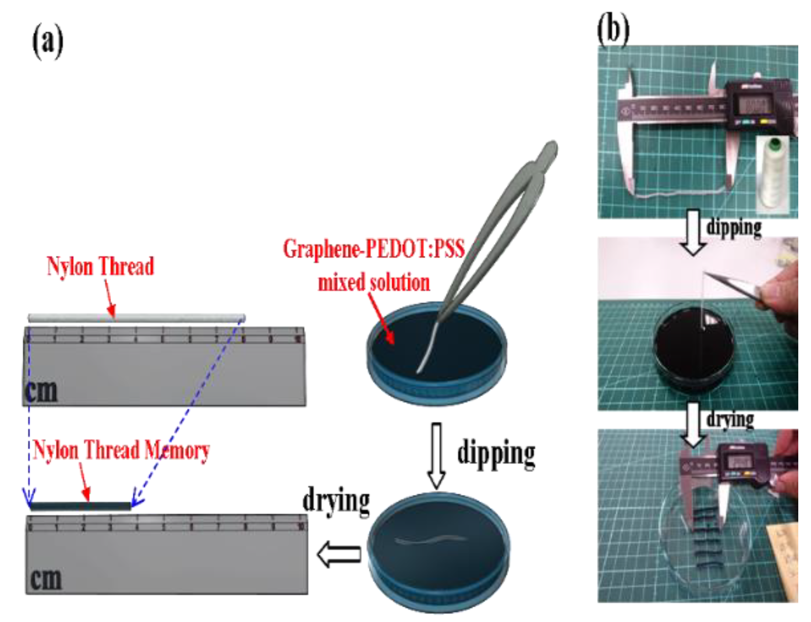
2. Materials and Methods

The simple dip-and-dry solution process with two steps was used to fabricate the non-volatile NT resistive memory [4]. The NT was composed of hundreds of nylon microfibers and a kind of telescopic NT purchased from a fabric shop. First, an elastic NT of a fixed length was dipped into the mixed solution with the graphene–PEDOT:PSS conductive ink for 6 min. In the second step, the NT was dried at room temperatures and under ambient conditions for two days to remove all the residual water. After the dipping and drying processes, the initial fixed length of the NT visibly decreased, as shown in Figure 1a. Figure 1b demonstrates an actual picture of the NT sample with the length reduction from 80 to 29.48 mm. In Figure 2, the wrapping of the graphene–PEDOT:PSS sheets around the NT was confirmed by the scanning electron microscopy (SEM) images. This result can be attributed to the cause of a contractive strain existing in the NT, further suggesting that a stretchable NT resistive memory can be performed. The contractive strain in the NT resistive memory is similar to the pre-strained elastomer effect [12]. In addition, the graphene–PEDOT:PSS conductive ink was synthesized using the electrolytic exfoliation method with two graphite rods placed in a liquid PEDOT:PSS electrolyte [13], and it was purchased from the Innophene Company Limited, (Pathum Thani), Thailand. The micro-Raman system (LabRAM HR, Horiba Jobin Yvon, Longjumeau, France) with an excitation energy of 2.33 eV (laser wavelength: 532 nm) was used to observe the spectral features of the graphene–PEDOT:PSSS sheets. The spectral features were reported in the previous study [4], demonstrating that lower defect states in the graphene were due to the presence of the D peak at ~1330 cm−1 and the multilayer graphene flakes were confirmed by the presence of the 2D peak at ~2670 cm−1 less than the G peak (not shown here). All electrical characteristics of the NT resistive memory were measured at room temperature with a Keithley 2400 source meter. An automatic horizontal stretching system (JSH-H1000, Japan Instrumentation System Company Limited, Kanagawa, Japan) was utilized to evaluate the piezoresistive characteristics of the NT resistive memory. A real setup picture of electrical and mechanical stretching measurements is shown in Figure 3.

3. Results and Discussion

3.1. WORM Characteristics

Figure 4 shows the current–voltage (I–V) characteristics of the non-volatile NT resistive memory. By sweeping voltage from 0 to 30 V at a speed of approximately 1.88 V/s, the NT resistive memory was switched from the low-resistance state (LRS) to the high-resistance state (HRS). The switching behavior is called the writing process. Although the applied voltage was swept again from 0 to 30 V (first voltage sweep), the NT resistive memory remained in the HRS and demonstrated to have typical WORM characteristics, further suggesting the permanent HRS caused by the current-induced PEDOT:PSS phase segregation [4]. The permanent HRS was confirmed by the second sweeping voltage from 0 to 3 V, as shown in Figure 4. To further understand the current conduction of the NT resistive memory, the LRS and the HRS currents can be explained by ohmic conduction and a tunneling model [14], respectively.

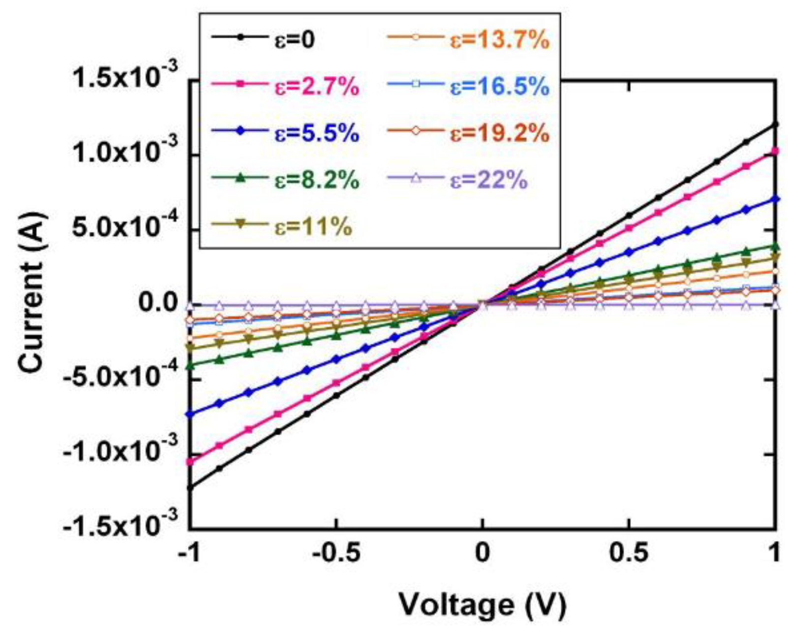
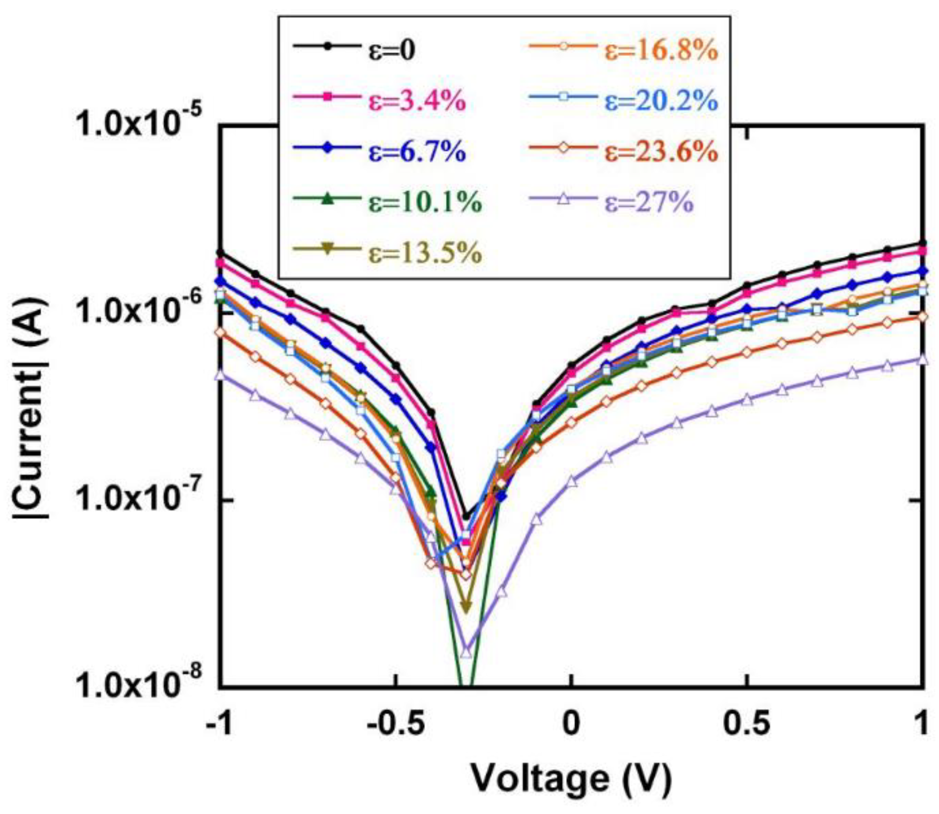
3.2. Piezoresistive Characteristics of the NT Resistive Memory

In order to evaluate the piezoresistive properties of the NT resistive memory, the GF is described using the following expression:
G F = Δ R R 0 ε
where R0 is the initial memory resistance without applied ε and ΔR is the change of the memory resistance under applied ε. While different ε values are applied to the NT resistive memory, the LRS and the HRS current characteristics are shown in Figure 5 and Figure 6, respectively.
Figure 7 shows the relation between ΔR/R0 and ε for the LRS and the HRS of the NT resistive memory. Here, the HRS resistance is defined as the reciprocal of the current measured at 1 V. The ΔR/R0 as a function of applied ε for the LRS is found to be more sensitive than that for the HRS. This result implies that the contribution of the local overlapping interconnection change in graphene–PEDOT:PSS composites to the LRS resistance change is greater than that to the HRS resistance change [9]. While the applied ε is less than 10%, the relation between ΔR/R0 and ε can determine the GF value based on Equation (1). For example, the GF for the LRS under applied ε = 8.2% can be determined to be approximately 24. Similarly, for the HRS under applied ε = 6.7%, a lower GF of approximately 6 can be found. While the applied ε is greater than 10%, an obvious increase in the GF of approximately 58 for the LRS under applied ε = 19.2% is found, further accounting for the possible cause of the overlapping interconnection loss and/or tunneling effect existing in graphene–PEDOT:PSS composites [9]. The LRS and the HRS data corresponding to Figure 7 are listed in Table 1 and Table 2, respectively.

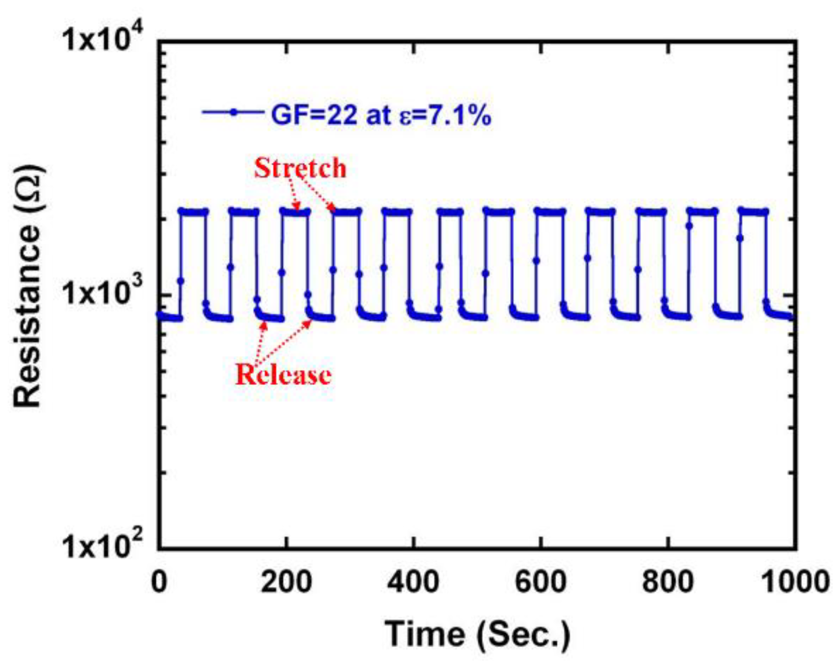
3.3. A Highly Sensitive and Durable Strain Sensor

To verify the highly sensitive sensing characteristics of the LRS, the repeated cycles of stretching and releasing the NT resistive memory are measured at a fixed ε = 7.1% with the horizontal stretching system of JSH-H1000. An obvious electromechanical response of the LRS with time is obtained and a high GF of approximately 22 is found in Figure 8, further accounting for the LRS with a highly piezoresistive sensing characteristic. This result suggests that the LRS of the textile-based NT resistive memory can serve as a highly sensitive and durable strain sensor for wearable e-textiles.

4. Conclusions

The simple dip-and-dry solution process has been proposed for the fabrication of the textile-based NT resistive memory. The textile-based NT resistive memory has shown to have typical WORM characteristics. The GF value of the LRS is found to be higher than that of the HRS. This result suggests that the contribution of the local overlapping interconnection change in graphene–PEDOT:PSS composites to the LRS resistance change is greater than that to the HRS resistance change. In addition, the textile-based NT resistive memory shows to have typical WORM characteristics and simultaneously its LRS serves as a highly sensitive and durable strain sensor. Finally, the actual integration of the NT resistive memory into textiles can provide resistive memory and piezoresistive sensor applications simultaneously for wearable e-textiles.

Funding

This research was supported by the Ministry of Science and Technology (MOST) under Contract No. MOST 107-2221-E-230-004.

Acknowledgments

The author would like to thank Y.C. Huang and J.W. Zhuang for their assistance in electrical measurements.

Conflicts of Interest

The author declares no conflicts of interest.

References

  1. Service, R.F. Electronic textiles charge ahead. Science 2003, 301, 909–911. [Google Scholar] [CrossRef] [PubMed]
  2. Pang, C.; Lee, G.Y.; Kim, T.I.; Kim, S.M.; Kim, H.N.; Ahn, S.H.; Suh, K.Y. A flexible and highly sensitive strain-gauge sensor using reversible interlocking of nanofibres. Nat. Mater. 2012, 11, 795–801. [Google Scholar] [CrossRef] [PubMed]
  3. Maccioni, M.; Orgiu, E.; Cosseddu, P.; Locci, S.; Bonfiglio, A. Towards the textile transistor: Assembly and characterization of an organic field effect transistor with a cylindrical geometry. Appl. Phys. Lett. 2006, 89, 143515. [Google Scholar] [CrossRef]
  4. Kang, T.K. Highly stretchable non-volatile nylon thread memory. Sci. Rep. 2016, 6, 24406. [Google Scholar] [CrossRef] [PubMed]
  5. Ding, Y.; Invernale, M.A.; Sotzing, G.A. Conductivity trends of PEDOT-PSS impregnated fabric and the effect of conductivity on electrochromic textile. ACS Appl. Mater. Interfaces 2010, 2, 1588–1593. [Google Scholar] [CrossRef] [PubMed]
  6. Zeng, W.; Shu, L.; Li, Q.; Chen, S.; Wang, F.; Tao, X.M. Fiber-based wearable electronics: A review of materials, fabrication, devices, and applications. Adv. Mater. 2014, 26, 5310–5336. [Google Scholar] [CrossRef] [PubMed]
  7. Yeon, C.; Kim, G.; Lim, J.W.; Yun, S.J. Highly conductive PEDOT:PSS treated by sodium dodecyl sulphate for stretchable fabric heaters. RSC Adv. 2017, 7, 5888–5897. [Google Scholar] [CrossRef]
  8. Seyedin, S.; Razal, J.M.; Innis, P.C.; Jeiranikhameneh, A.; Beirne, S.; Wallace, G.G. Knitted strain sensor textiles of highly conductive all-polymeric fibers. ACS Appl. Mater. Interfaces 2015, 7, 21150–21158. [Google Scholar] [CrossRef] [PubMed]
  9. Eswaraiah, V.; Balasubramaniam, K.; Ramaprabhu, S. One-pot synthesis of conducting graphene-polymer composites and their strain sensing application. Nanoscale 2012, 4, 1258–1262. [Google Scholar] [CrossRef] [PubMed]
  10. Yao, S.; Swetha, P.; Zhu, Y. Nanomaterial-enabled wearable sensors for healthcare. Adv. Healthcare Mater. 2018, 7, 1700889. [Google Scholar] [CrossRef] [PubMed]
  11. Hu, L.; Pasta, M.; Mantia, F.L.; Cui, L.F.; Jeong, S.; Deshazer, H.D.; Choi, J.W.; Han, S.M.; Cui, Y. Stretchable, porous, and conductive energy textiles. Nano Lett. 2010, 10, 708–714. [Google Scholar] [CrossRef]
  12. Zhang, Y.; Wang, S.; Li, X.; Fan, J.A.; Xu, S.; Song, Y.M.; Choi, K.J.; Yeo, W.H.; Lee, W.; Nazaar, S.N.; et al. Experimental and theoretical studies of serpentine microstructures bonded to prestrained elastomers for stretchable electronics. Adv. Funct. Mater. 2014, 24, 2028–2037. [Google Scholar] [CrossRef]
  13. Lotya, M.; Hernandez, Y.; King, P.J.; Smith, R.J.; Nicolosi, V.; Karisson, L.S.; Blighe, F.M.; De, S.; Wang, Z.; McGovern, I.T.; et al. Liquid phase production of graphene by exfoliation of graphite in surfactant/water solutions. J. Am. Chem. Soc. 2009, 131, 3611–3620. [Google Scholar] [CrossRef] [PubMed]
  14. Kang, T.K. Tunable piezoresistive sensors based on pencil-on-paper. Appl. Phys. Lett. 2014, 104, 073117. [Google Scholar] [CrossRef]
Figure 1. (a) Schematic of the simple two-step dip-and-dry solution process for the fabrication of the non-volatile nylon thread (NT) resistive memory. (b) An actual picture of the NT sample with the length reduction from 80 to 29.48 mm.
Coatings 09 00623 g001
Figure 2. SEM images of the NT samples at magnifications of (a) 200×, (b) 500×, (c) 1000×, and (d) 1500×.
Coatings 09 00623 g002
Figure 3. A real setup picture of electrical and mechanical stretching measurements.
Coatings 09 00623 g003
Figure 4. Current–voltage (I–V) characteristics of the NT resistive switching memory from the low-resistance state (LRS) to the high-resistance state (HRS). The I–V fitting lines of the LRS and the HRS are also calculated to understand the possible mechanisms. The blue and pink arrows indicate the sweeping voltage directions of the LRS and the HRS, respectively.
Coatings 09 00623 g004
Figure 5. LRS current characteristics for the NT resistive memory under applied different ε values.
Coatings 09 00623 g005
Figure 6. HRS current characteristics for the NT resistive memory under applied different ε values.
Coatings 09 00623 g006
Figure 7. Plots of relative resistance change (ΔR/R0) versus stretching strain (ε) for the LRS and the HRS of the NT resistive memory.
Coatings 09 00623 g007
Figure 8. Many cycles of repeatedly stretching and releasing the LRS of the NT resistive memory under applied a fixed ε = 7.1%. The GF value of the LRS can be determined to be approximately 22 at the fixed ε = 7.1%.
Coatings 09 00623 g008
Table 1. Listed LRS data of ΔR/R0 versus ε for the gauge factior (GF) calculation.
εΔR/R0GF
0.0000.000.00
0.0270.165.97
0.0550.6812.35
0.0822.0224.48
0.1103.0127.39
0.1374.4132.13
0.1658.7152.85
0.19211.1858.14
0.220609.932775.16
Table 2. Listed HRS data of ΔR/R0 versus ε for the GF calculation.
εΔR/R0GF
0.0000.000.00
0.0340.113.15
0.0670.405.94
0.1010.777.63
0.1350.795.86
0.1680.663.91
0.2020.834.10
0.2361.476.25
0.2693.1411.66

