Article

Structure, Mechanical and Tribological Properties of Me-Doped Diamond-Like Carbon (DLC) (Me = Al, Ti, or Nb) Hydrogenated Amorphous Carbon Coatings

1
ICD LASMIS, Université de Technologie de Troyes, UMR6281, CNRS, Antenne de Nogent, Pôle Technologique de Sud-Champagne, 52800 Nogent, France
2
NICCI (Nogent International Center for CVD Innovation), LRC CEA-ICD LASMIS, Université de Technologie de Troyes, Antenne de Nogent, Pôle Technologique de Sud-Champagne, 52800 Nogent, France
*
Author to whom correspondence should be addressed.
Coatings 2018, 8(10), 370; https://doi.org/10.3390/coatings8100370
Submission received: 7 September 2018 / Revised: 4 October 2018 / Accepted: 15 October 2018 / Published: 19 October 2018

Abstract

:
Metal containing hydrogenated diamond-like carbon coatings (Me-DLC, Me = Al, Ti, or Nb) of 3 ± 0.2 μm thickness were deposited by a magnetron sputtering-RFPECVD hybrid process in an Ar/H2/C2H2 mixture. The composition and structure were investigated by Energy Dispersive X-ray Spectroscopy (EDS), X-ray Diffraction (XRD), X-ray photoelectron spectroscopy (XPS), and Raman spectroscopy. The residual stress was measured using the curvature method and nanoindentation was used to determine the hardness and the Young’s modulus. A Ball-on-disk tribometer was employed to investigate the frictional properties and sliding wear resistance of films. The results show that the properties depend on the nature and the Me content in the coatings. The doping of the DLC coatings leads to a decrease in hardness, Young’s modulus, and residual stresses. Wear rate of the films first decreases with intermediate Me contents and then increases for higher Me contents. Significant improvements in the friction coefficient on steel as well as in the wear rate are observed for all Al-DLC coatings, and, concerning the friction coefficient, the lowest value is measured at 0.04 as compared to 0.07 for the undoped DLC.

1. Introduction

Diamond-like carbon (DLC) is a metastable form of amorphous carbon with sp2-bonded clusters interconnected by a random network of sp3-bonded atomic sites [1]. The properties of such coatings are directly related to the hybridization state of carbon bonds and the hydrogen content. The combination of chemical inertness, low friction coefficient, high hardness, and good wear resistance make DLC films very suitable for a wide variety of biomedical [2,3,4,5,6,7,8,9], mechanical [10,11,12,13] and tribological applications [14,15,16,17,18,19,20]. However, the high compressive stress, which limits the thickness of coatings, represents a main disadvantage of DLC coatings. One of the methods to reduce the stress are based on the use of different film compositions, for instance, with silicon addition [21] or multi layered architectures [22]. Recently, metal-containing hydrogenated diamond-like carbon coatings (Me-DLC) have attracted great interest since their initial appearance two decades ago [23,24,25]. The Me-C:H coating has high elasticity and a low friction coefficient, which can be useful for many engineering applications [26,27,28,29,30]. In addition, the hardness can be adapted to find a compromise between excellent running behavior and a low friction coefficient.
The studies deal mainly with the doping of DLC coatings with a single element, such as Ti [31,32,33,34,35], Cr [36,37,38], W [39,40], Al [41,42,43], and Cu [44,45], while few studies compare the use of different metal dopants [46]. The purpose of this work is to investigate the influence of the nature and the content of doping metal elements on the physicochemical, mechanical, and tribological properties of Me-DLC coatings deposited by a magnetron sputtering-RFPECVD hybrid process. A weak carbide former metal (Al) and two strong carbide former metals (Ti or Nb) were used to dope the DLC films. Me-DLC (Me = Al, Ti, or Nb) coatings with various Me contents were synthesized on AISI M2 steel and Si substrates. The effects of the Me content on the structure, mechanical, and tribological properties of the DLC coatings were consistently investigated. These Me-DLC coatings were deposited by a hybrid deposition process combining RFPECVD for deposition of DLC films and magnetron sputtering for Me-doping. This hybrid process combines both the advantages of the PECVD technique, such as low deposition temperature, uniformity, and a large scale deposition, and the magnetron sputtering technique offering a wide range of doping source choices (solid targets).

2. Experimental Details

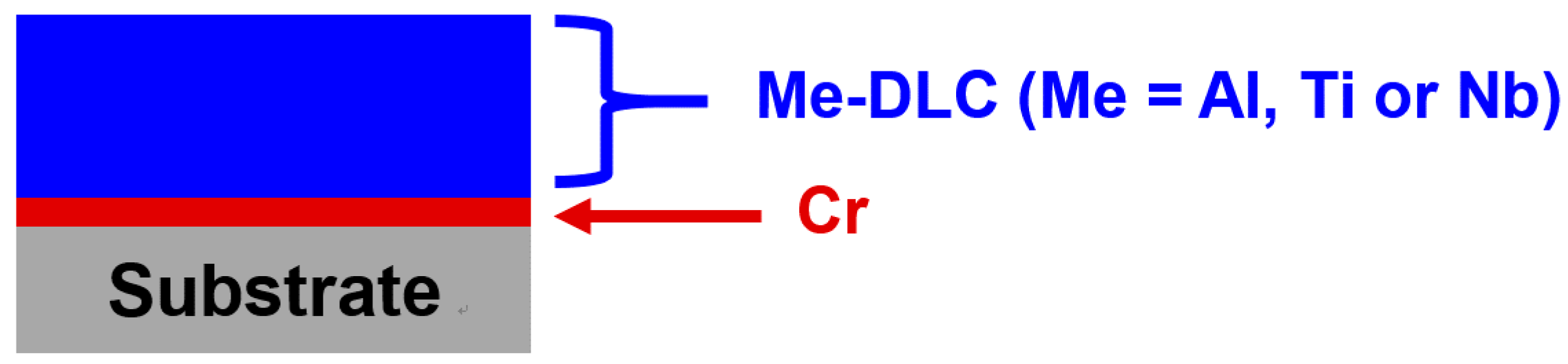
2.1. Coatings Deposition

Me-DLC (Me = Al, Ti, or Nb) coatings were deposited on AISI M2 steel substrates using a hybrid RF-PECVD and DC magnetron sputtering (PLASSYS-MP450) deposition system. The system as well as the process are described in [47]. The substrates were polished to a mirror-like surface finish, and cleaned ultrasonically in an acetone bath for 15 min. The substrates were placed on the holder that was rotated at a speed of 5 rpm, 8 cm away from the metal target. Four targets (200 × 100 × 6 mm3, 99.95% purity) were used to deposit the Me-DLC coatings. Titanium, niobium, and aluminum targets were used to deposit metal-doped DLC coatings while a chrome target was used to deposit the adhesion interlayer. C2H2 is used as the precursor (N45, purity > 99.95%) for the synthesis of the DLC. It is diluted with H2 hydrogen (Alphagaz 1) and Ar argon (Alphagaz 1). The vacuum base pressure of the deposition chamber was 1.5 × 10⁻⁶ mbar (1.5 × 10⁻⁴ Pa). The substrates were also cleaned by an argon discharge at 1.5 Pa (100 sccm) working pressure and RF discharge power of 200 W (−300 V) for 60 min prior to deposition. In order to insure a good adhesion between Me-DLC coating and steel substrate, a chromium interlayer was deposited by magnetron sputtering of a Cr target (1 A, Ar 100 sccm, 1.5 Pa). Then, DLC films were deposited using a gas mixture of C2H2, H2 and Ar with a ratio of 10/05/100 (sccm). Metal content was controlled via the target current within the range of 0.5–2.6 A. Deposition parameters are given in Table 1 and a schematic architecture of Me-DLC coatings is shown in Figure 1. The thicknesses of the as-deposited layers are obtained from the measurement using an optical profilometer, after the removal of a mask stuck on the substrates before deposition.

2.2. Composition and Structure Characterizations

The chemical composition of the Me-DLC coatings was obtained by energy dispersive spectroscopy (EDS) analyses (Bruker Nano GmbH, Berlin, Germany) applying an accelerating voltage of 20 kV. The film thicknesses were 3 ± 0.5 μm. X-ray Photoelectron Spectroscopy (XPS) (Thermo Scientific, Waltham, MA, USA), with a monochromatic Al Kα irradiation (hν = 1486.6 eV), was used to analyze composition and chemical bond. A primary sputtering by Ar+ ions, during 60 s with a passing energy of 50 eV was achieved to remove surface contaminants. X-ray diffraction was performed to characterize the structure of Me-DLC coatings. A D8-ADVANCE goniometer from Bruker advance (Karlsruhe, Germany) was used with Bragg–Brentano geometry. It is equipped with a copper anticathode (λ = 1.54 Å) and a LynxEye XE detector. The treatments of the diffractograms and the identification of the crystalline phases were made using EVA software. The carbon atoms arrangement was analyzed using Raman scattering spectroscopy (Horiba Jobin-Yvon LabRam Raman confocal spectrometer (341-K), Palaiseau, France) with a He/Ne laser (λ = 632.8 nm) (E = 1.96 eV). To prevent damage to the coating, the laser power on the sample was 0.6 mW with a lateral resolution of the order of a micrometer. For all measurements, a 1800 grooves/mm diffraction grating, a confocal hole diameter of 200 µm, and a spectrograph entrance slit of 150 µm were used. All of the measurements were recorded for a spectral range of 600 to 2000 cm−1, under the same conditions (30 s of integration time).

2.3. Mechanical Properties

Residual stress in the coatings was determined by measuring the curvature radius of the substrate, before and after deposition, using a tactile profilometer (Altisurf 500, Altimet, Marin, France). The stress value is calculated from Stoney’s equation (Equation (1)) [48]. The substrates were rectangular iron foils (60 × 3 × 0.1 mm3).
σ = E s ( 1 ν s ) t s 2 6 t f ( 1 R 1 1 R 2 )
where Es and νs the modulus of elasticity and the Poisson’s ratio of the substrate, R1 and R2 the radius of curvature of the iron substrate before and after deposition, respectively. ts and tf are the substrate and coating thicknesses, respectively. The Poisson’s ratio of the substrate is 0.27 and its Young’s modulus is 208 GPa [49]. The iron foils used for residual stress measurements underwent a thermal stress relieving treatment (annealing: temperature rise for 1 h, with a hold at 600 °C for 2 h, then slow cooling to room temperature). This treatment was carried out in a secondary vacuum.
Hardness and Young’s modulus of the coatings (about 3 ± 0.5 µm thick) were determined by an instrumented nanoindentation technique while using a Nano XP nanoindenter, MTS Systems Corporation (now KLA Tencor, San José, CA, USA) with a Berkovich diamond tip. Twelve indentations in single penetration mode were carried out on each of the layers deposited on steel substrates. The maximum penetration depth of the indenter was 400 nm.

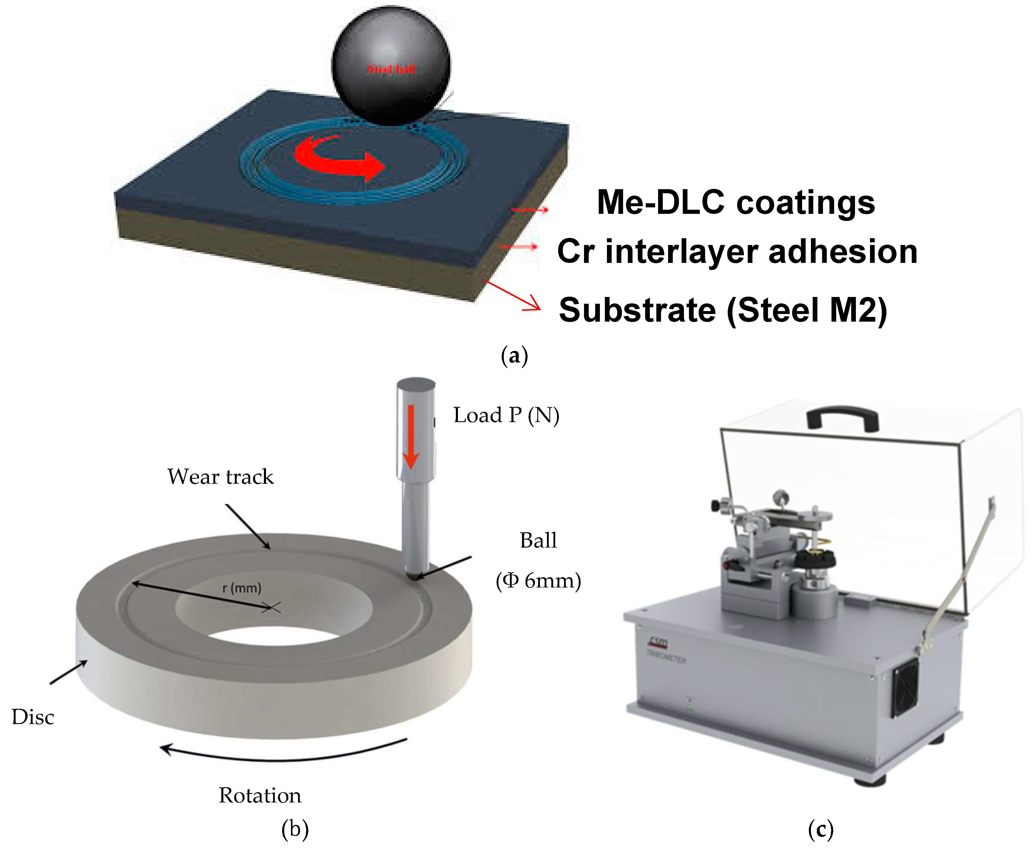
2.4. Friction and Wear Testing

The tribological behaviour of Me-DLC coatings was evaluated on a ball-on-disc tribometer (Figure 2) (CSM Instruments, now Anton Paar, Neuchatel, Switzerland) under dry sliding conditions. A 6 mm diameter alumina ball was used as the counter body. All of the tests were performed at a sliding velocity of 10cm/s for a sliding distance of 2525 m (100,000cycles) and the applied normal load was 10 N; the reciprocating frequency was 10 Hz. These parameters are summarized in Table 2. After tests, the surface profiles of the wear tracks were measured while using a tactile profilometer (Altisurf 500, Altimet, Marin, France). The wear rates of tested coatings were calculated using the following equation (Equation (2)).
K = V/[N × L]
where K is wear rate, V is wear volume loss, N is applied normal load, L is total sliding distance.

3. Results and Discussion

3.1. Chemical Composition and Structure

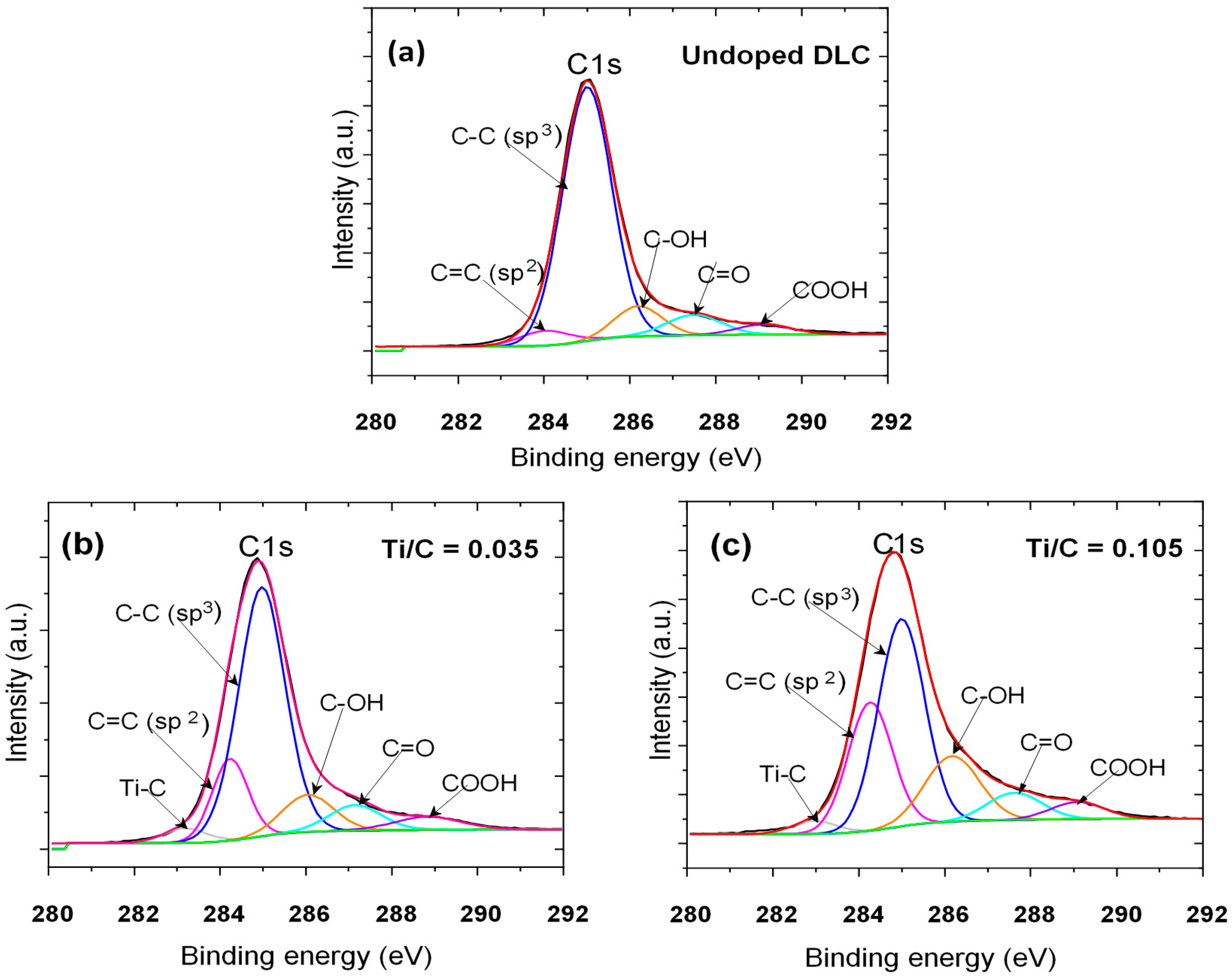
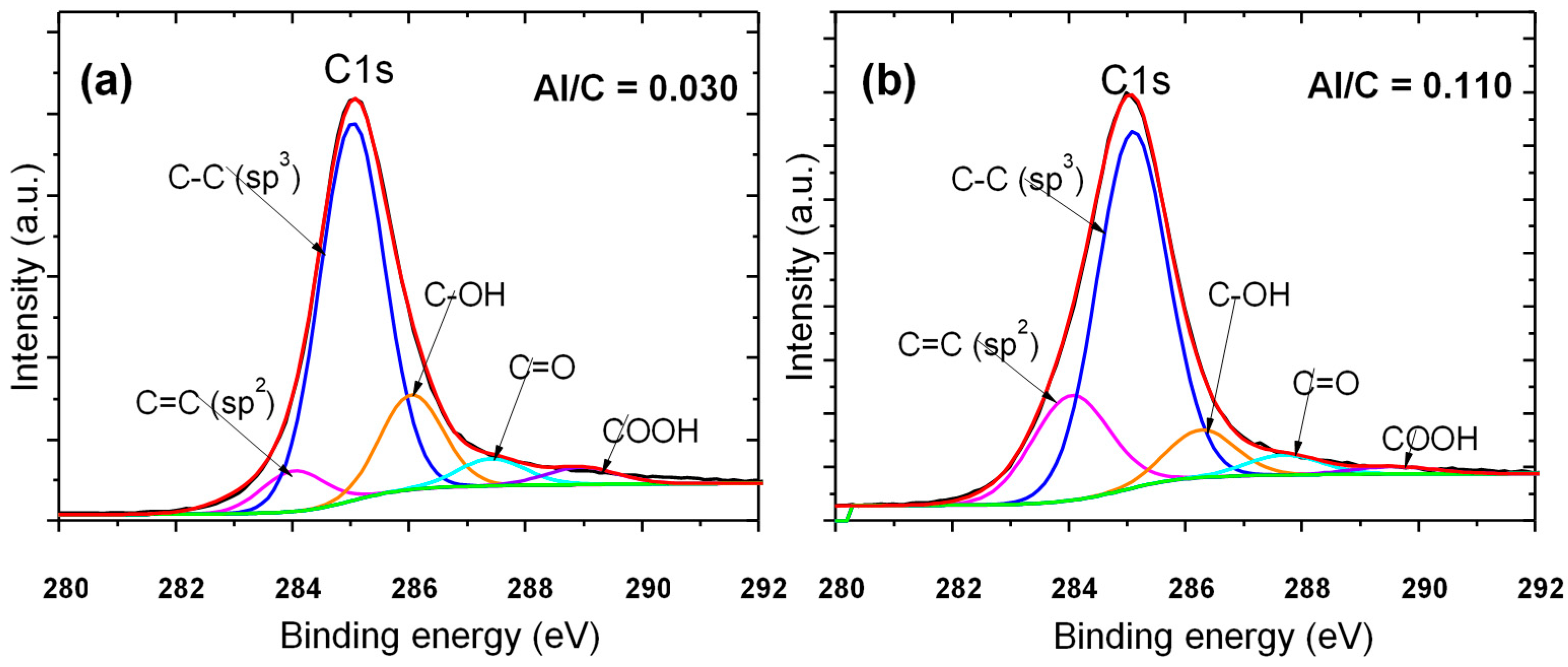
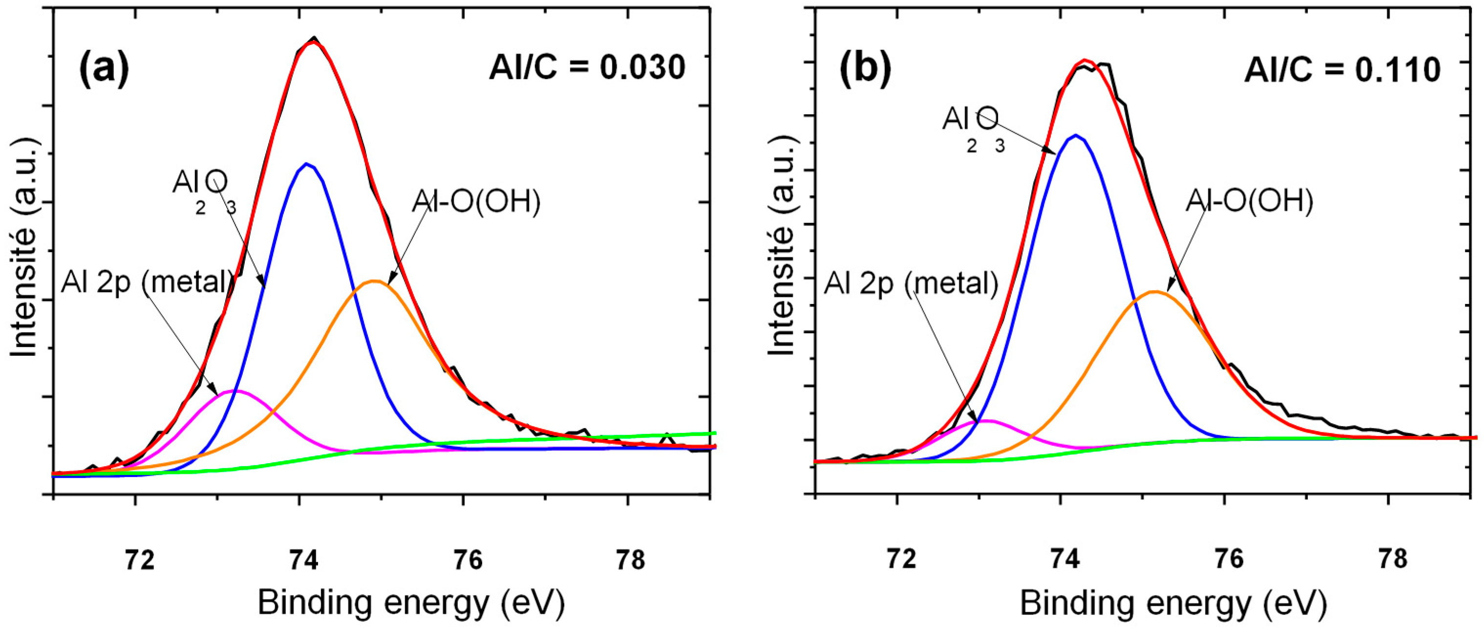
3.1.1. Chemical Composition
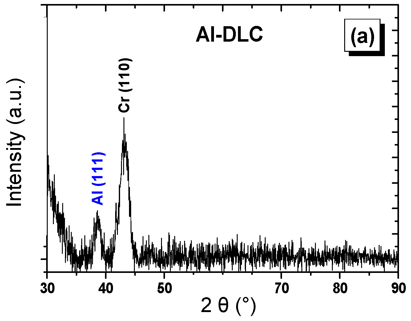
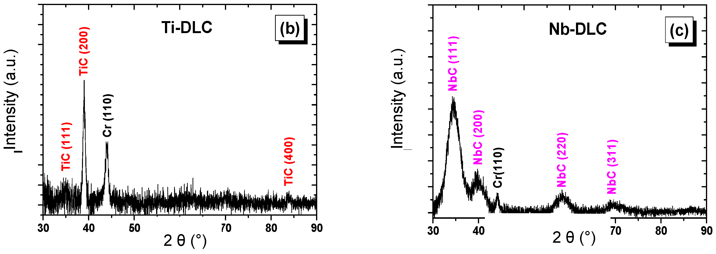
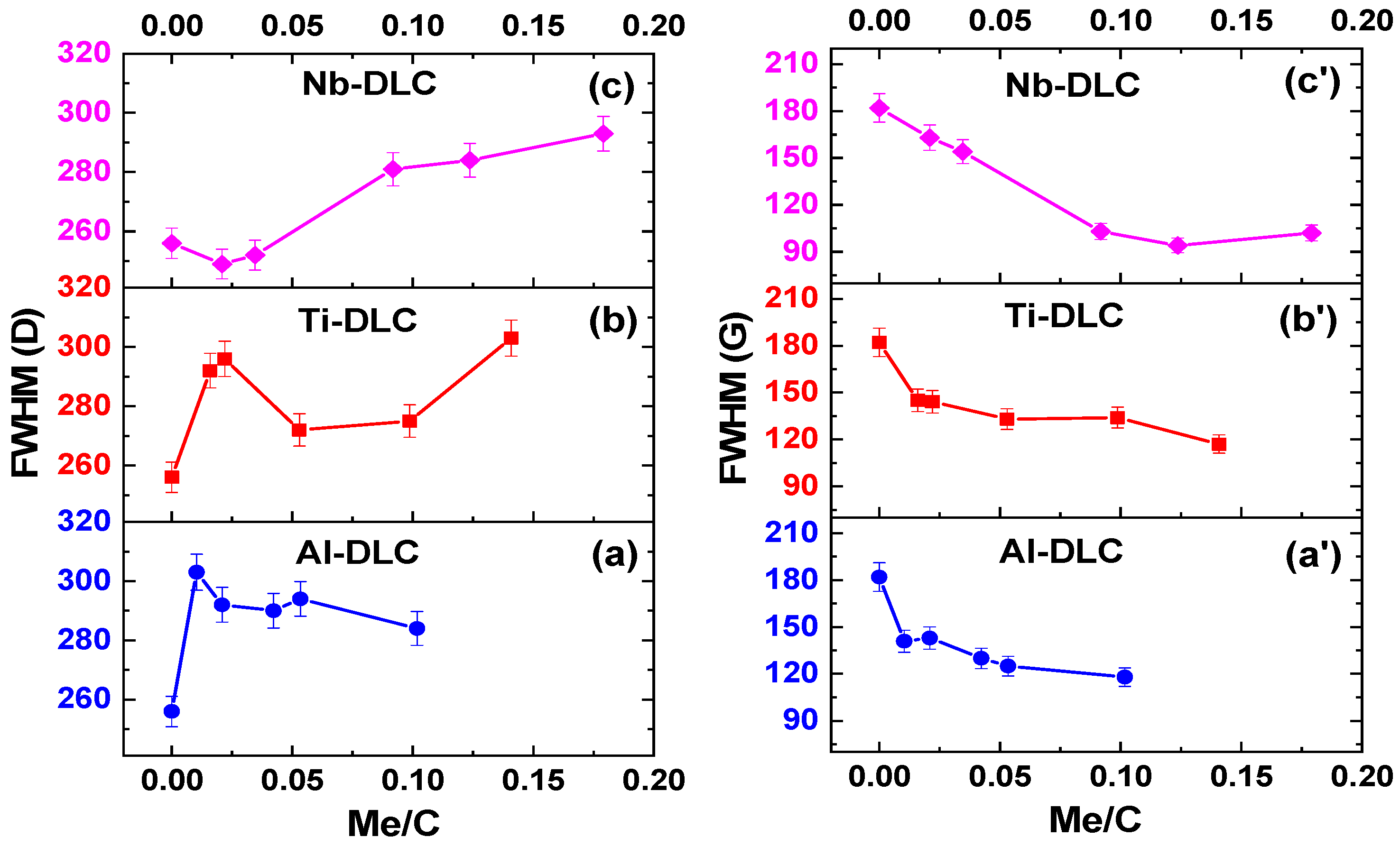
Adjustment of metal content in the Me-DLC coatings is controlled by the variation of the metallic target current. The chemical composition of the samples is calculated from EDS analysis. The Me/C ratio representing the chemical composition of the coatings is shown in Table 3. The results show an increase in the Me/C ratio as a function of the metallic target current. This confirms the doping efficiency by this type of PECVD/magnetron sputtering hybrid process.

3.1.2. Structure

Figure 3 shows XRD spectra corresponding to Me-DLC (Me = Al, Ti or Nb) coatings grown on glass substrates. Only the heavily doped coatings reveal a crystallized phase (Al, TiC, NbC). For the three coatings Al-DLC, Ti-DLC, and Nb-DLC, the peak corresponding to the Cr (110) position at approximately 44.388° is associated with the adhesion Cr interlayer. As expected, the Al (111) peak of metallic aluminum is detected at about 2θ = 38.562° (Figure 3a). Aluminum is poorly crystallized and it is embedded in the amorphous carbon matrix in its metallic form. For Ti-DLC and Nb-DLC coatings, metal carbides phases of cubic structure were observed, as shown in Figure 3b,c, respectively. As reported in other work, TEM analyses have indeed revealed that the samples consisted of amorphous structures containing nanometric metal grains [50], as well as nanocrystals of crystalline cubic metal carbide phases [51]. No crystalline structure was detected in our coatings with less metal, which are solid solutions of metal in the amorphous phase. TEM analysis should be carried out to confirm the XRD results.
The chemical bonds of pure DLC and Me-DLC films with different Me (Al, Ti) contents were analyzed by X-ray photoelectron spectroscopy (XPS). Figure 4 and Figure 5 show the corresponding high-resolution C1s and Ti2p core level spectra respectively for Ti-DLC. Figure 6 and Figure 7 show the C1s and Al2p high-resolution XPS spectra, respectively, of Al-DLC coatings. In this study, all spectra were calibrated at 285 eV (Csp3).
The peak fitting of the C1s region (Figure 4 and Figure 6) shows six types of carbon species for Ti-DLC and Al-DLC coatings and five for undoped DLC. They include two contributions: aromatic C=C at 284.4 eV and aliphatic C–C at 285 eV. These contributions are attributed, respectively, to sp3 and sp2 hybridization of carbon. sp3 hybridization is attributed to diamond and sp2 hybridization is attributed to the presence of graphite. We can notice that the sp2 composition of the signal C1s increases at the expense of that of the sp3 carbon hybridation when the Ti/C and Al/C ratios increase. In other words, the incorporation of titanium or aluminum into the coatings promotes the graphitic phase of carbon. The C1s signal also contains carbon hydroxide C–OH at 286 eV, carbon carboxylate COO at 287, and carbonyl C=O at 288 eV. These components are associated with oxygen in the layers. In addition, according to the literature, the low energy contribution of 283 eV on the C1s spectrum is attributed to titanium carbide TiC (Figure 4) [52]. However, no aluminum carbide peak is detected (about 281.5 eV) in the C1s spectra of Al-DLC coatings (Figure 6).
The Ti2p spectrum (Figure 5) was fitted with three doublets, each being separated by 6 ± 0.5 eV, corresponding to titanium carbide TiC (Ti 2p3/2 to 455.0 eV, Ti 2p1/2 to 461.0 eV) and titanium oxides; TiO (Ti 2p3/2 at 454.6 eV, Ti 2p1/2 at 460.2 eV) and TiO2 (Ti 2p3/2 at 458.9 eV, Ti 2p1/2 at 464.6 eV) [53], respectively.
Figure 7 reveals that the Al2p XPS spectra, decomposed into three contributions, have a binding energy at about 74.5 eV [54] corresponding to the peak Al–O, at 73 eV [55] associated with metallic Al and at 75 eV corresponding to AlOOH. This indicates that Al incorporated in the carbon matrix exists mainly in the metallic and/or oxide form. These results confirm those that were obtained by XRD analysis.
Raman spectroscopy is a fast and non-destructive tool widely used for the characterization of DLC structures [56,57,58,59]. Usually, the Raman spectroscopy analysis of DLC films favors the 1000–1700 cm−1 region largely dominated by the bands originating from the A1g breathing (D-band) carbon bonded mode of sp2 disordered carbon atoms sites as aromatic rings structure and E2g stretching (G-band) carbon bonded mode of all pairs of sp2 disordered carbon atoms as both aromatic and olefinic molecules. The G-band so-called graphitic-band is centered in the range 1500–1630 cm−1 and D-band (D for disordered) is located at about 1350 cm−1.
The relative ratio of the D peak to G peak (ID/IG), their positions and their FWHM (Full Width at Half Maximum) can be used to characterize the sp3/sp2 bonding ratio. ID/IG and the peak positions of G and D bands were presented as a function of Me/C ratio in [47]. A sharp increase in the ID/IG ratio is observed when the metal dopants are incorporated in the DLC films. Then, ID/IG increases moderately as the dopant content increases further. This result, usually associated with a decrease in the Csp3 fraction, is attributed to the increasing disorder within the structure of all Me-DLC coatings [60]. It is also the sign of an increase in the size of the sp2 type aggregates contained in the carbon matrix [56,59,60]. A stabilization of the ID/IG ratio was observed for Nb-DLC coatings for high values of the Nb/C ratio [47]. This is associated with a stabilization of the disorder for the high metallic content elements, related to the maintenance of the organization of graphitic clusters Csp2 that are present in the carbon matrix [1]. At the same time, an increase in the positions of the two bands D and G towards the large wave numbers is observed as a function of the metal content in the coatings, as shown in [47].
In general, the displacement of the band G towards the large wave numbers is attributed to the increase of the Csp2 component (aromatic and/or chain cycles) [61], associated with the confinement of the π electrons in short chains, and the displacement of the position of the D band is associated with a decrease in the disorder of the sp2 aromatic clusters [62]. Furthermore, the increase in FWHM (D), as observed in the cases of Me-DLC (Figure 8), can be associated with an increase in the number of graphitic clusters. Thus, the decrease of FWHM (D) and FWHM (G) indicates a relaxation of the distortions and consequently a gradual reduction of the defects in the carbon network Csp2 [1].
On the basis of these observations, we can suggest that the incorporation of a metallic element (Al, Ti, or Nb) in the amorphous matrix of carbon leads, at first, to a disorder in DLC. This disorder is linked to the change of carbon from its chain form to aromatic rings form. Then, this disorder decreases when the nanocrystalline form of graphite begins to set up, this when the metal content becomes high in Me-DLC coatings.

3.2. Mechanical Properties

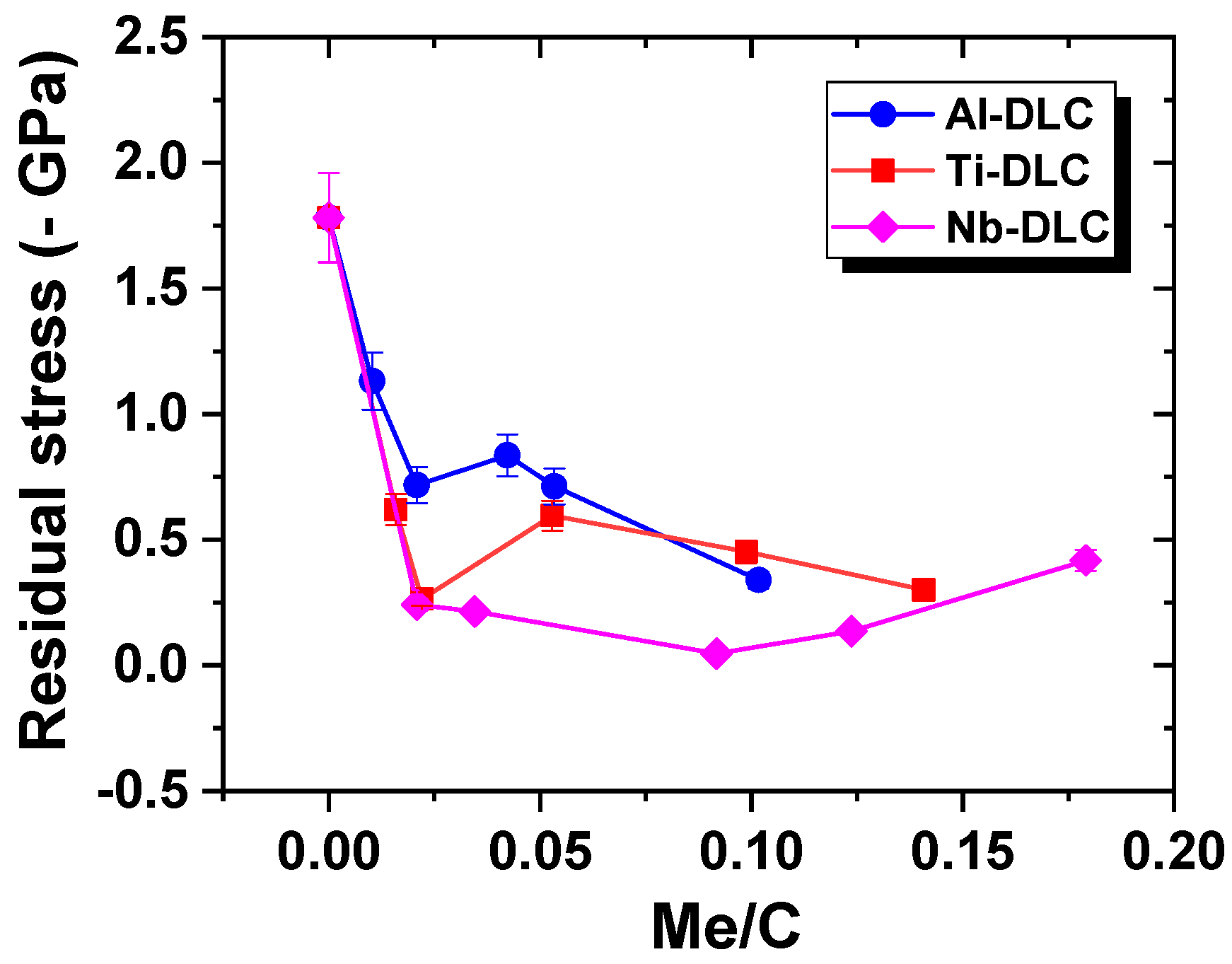
3.2.1. Residual Stress

Evolution of residual stress in the Me-DLC films with Me/C ratio is shown in Figure 9 and results demonstrate a remarkable decrease in residual stresses, for all coatings, when the metal dopants are incorporated into the carbon matrix. As compared to an undoped DLC (1.8 GPa), the residual stresses reach a value of 0.22 GPa for an Al/C ratio equal to 0.10. Concerning Ti-DLC coatings, a significant decrease in residual stresses (between 0.6 and 0.8 GPa) is observed as soon as small concentrations of Ti are introduced into the DLC coatings. This same effect is also observed for the Nb-DLC, where the residual stresses reach very low values. The lowest value, which is 0.02 GPa, was obtained for a Nb-DLC coating with a Nb/C ratio of 0.09.
The effect of strong carbide formers (titanium and niobium) is more pronounced than that of aluminium. It is assumed that this different behaviour can be explained by a different evolution of structure. As it has been shown in Section 3.1, Ti or Nb addition leads to carbide clusters/aggregates by creating bonds with carbon that break the DLC bonds and break the continuity of the carbon matrix. On the other hand, Al is dispersed in the carbon matrix and has a significant effect only for a Al/C ratio above 0.5. Similar evolutions of internal stresses of the DLC coatings, as a function of the metal content, were also obtained by Dai and Wang for Al-DLC coatings [40], and by C. Corbella for Me-doped DLCs (W, Mo, Nb, and Ti) [45]. According to their model, Choi et al. [63] suggest that the stress reduction in Me-DLC coatings is possible without significant deterioration of mechanical properties due to the pivotal role of the metal atoms; a distortion of the angle of the atomic bond may occur without a significant increase in elastic energy, which may be considered as resulting from weak and less directional Me-C bonds.

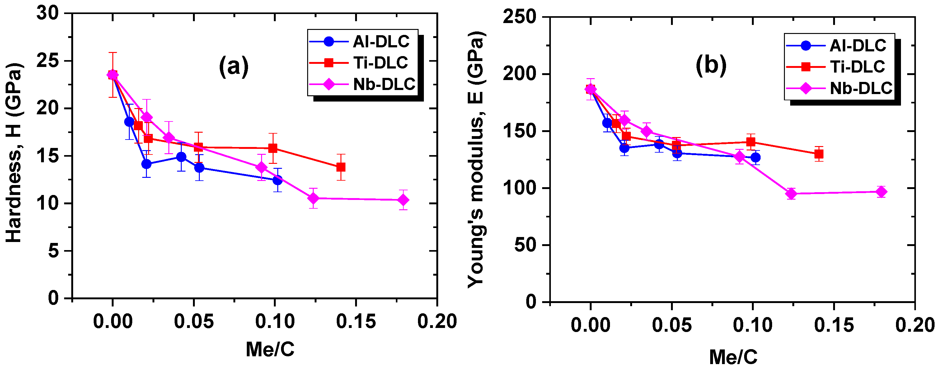
3.2.2. Hardness and Young’s Modulus

The undoped DLC has a hardness of 23.6 GPa and a Young’s modulus of 197 GPa and it can be observed that these values decrease when metal is incorporated in a carbon matrix (Figure 10). Hardness is in the range of 20 to 12 ± 2 GPa for Al-DLC, Ti-DLC, and Nb-DLC coatings and Young’s modulus is between 95 and 170 ± 5 Gpa, with the increase in the Me/C ratio. This drop in hardness and Young’s modulus of Me-DLC coatings can be an effect of the microstructural rearrangements of the Me and/or MeC nanoparticles in the DLC matrix. The mechanical properties of DLC coatings depend mainly on the sp3 carbon content. According to the Raman results mentioned in Section 3.2, the incorporation of metal atoms has a strong effect on the increase of the ID/IG ratio associated with the decrease of the Csp3/Csp2 ratio. This results in a decrease in the hardness and Young’s modulus of the Me-DLC coatings.

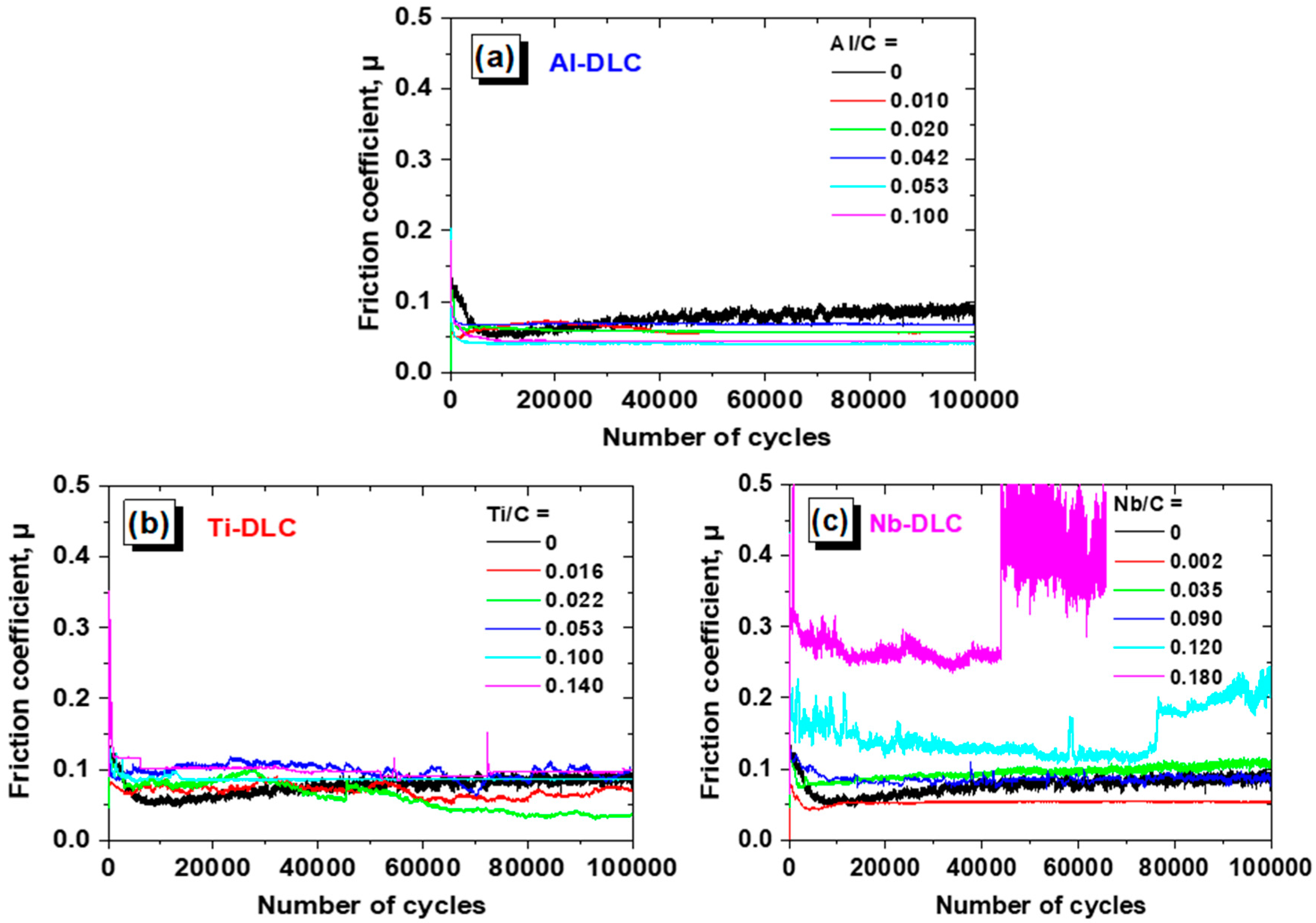
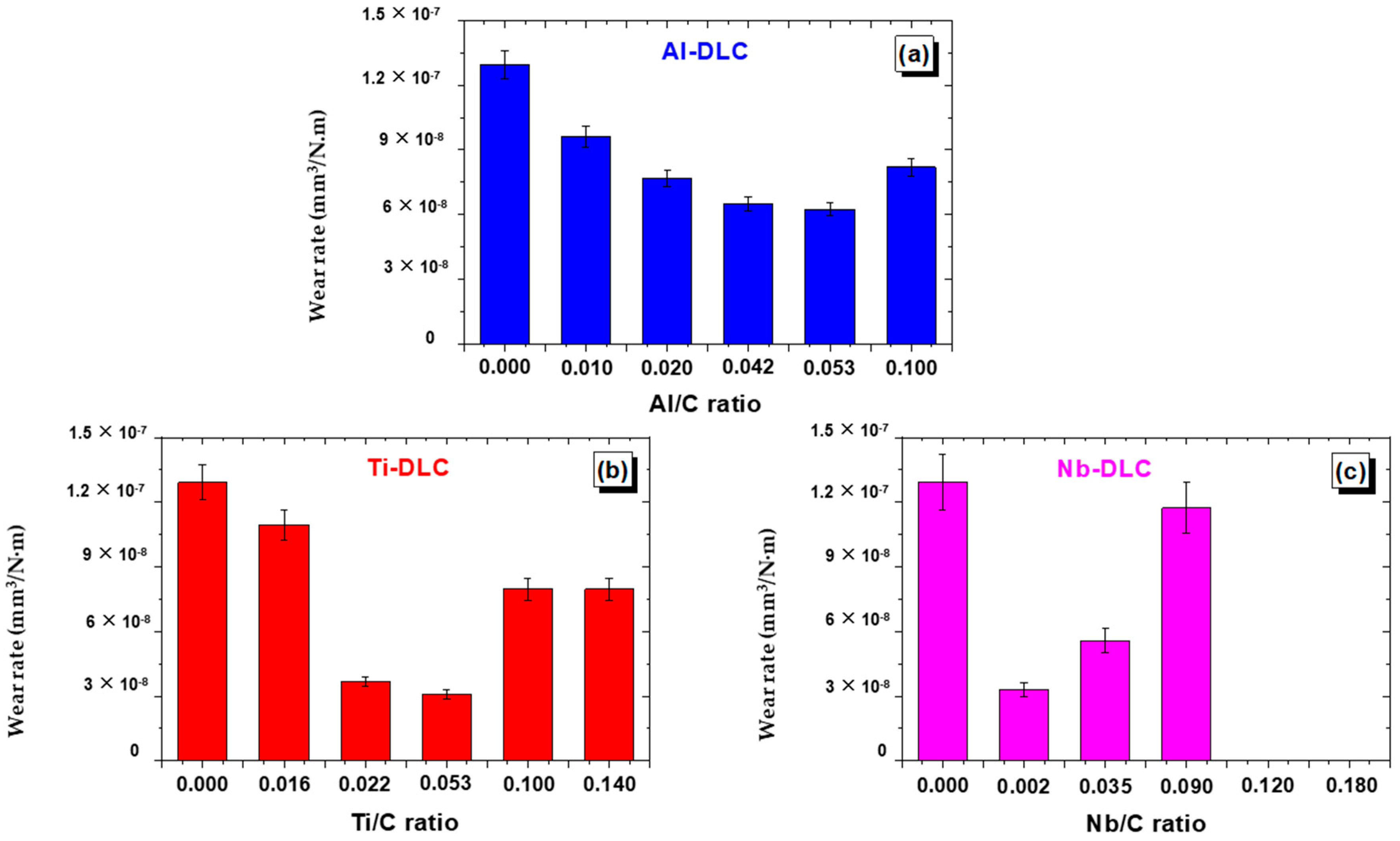
3.3. Tribological Performances

Figure 11 shows the friction behavior of Me-DLC as compared with that of undoped DLC. In the case of aluminum, a significant improvement in the coefficient of friction is observed for all Al-DLC coatings and the lower value is measured at 0.04 (Figure 11a). Moreover, profiles show a great stability of the friction coefficient from the first cycles to the end of the tests. These values are lower than that of undoped DLC (µ = 0.07). The friction profiles of Ti-DLC coatings (Figure 11b) reveal a more or less stable behavior and show an improvement in the case of Ti/C = 0.022. Like for Ti-DLC coatings, Nb-DLC coatings show a decrease in friction coefficients for a weak Nb doping (Figure 11c). For higher Nb contents, (Nb/C = 0.180, for example), the coefficient of friction increases and becomes higher than that of the undoped DLC. The average friction coefficient of DLC coatings decreases when low metal element concentrations are incorporated into the carbon matrix. Then, for higher levels, the coefficient of friction continues to decrease in the case of Al-DLC coatings, while it begins to increase for Ti-DLC and Nb-DLC coatings.
By incorporating Me (Me = Al, Ti or Nb) dopants in the DLC coatings, the fraction of the sp2 phase increases, which favours the lubrication properties [31,64,65], and, thus, a lower friction coefficient for weak metal contents. It is usually admitted that the low friction coefficient of DLC coatings is due to wear induced graphitization, which occurs from a localized increase in temperature at the tribological contacts. As a result, a low shear graphitic intermediate layer is formed between the ball material and the coating, thereby reducing friction (tribofilm). As the aluminum content increases, the friction coefficient of the Al-DLC coatings continues to decrease, which could be associated with surface oxidation and/or to an optimal aluminum content in the coatings that are associated with an optimal size and distribution of the sp2 clusters in the DLC matrix. However, when the concentration of Ti or Nb is high (Ti/C ≥ 0.110 and Nb/C ≥ 0.090), the friction coefficient increases. This may be due to the large amount of carbides that play a role as an abrasive body that breaks down the carbon matrix and causes severe wear. In this case, the increase of roughness when Ti or Nb increase in Ti-DLC and Nb-DLC coatings, as discussed in [47], can explain the increase of friction coefficients of these coatings.
Figure 12 shows the wear rate of Me-DLC (Me = Al, Ti or Nb) as a function of the Me/C ratio. Wear resistance of the Me-DLC coatings is significantly improved as compared to that of undoped DLC (Figure 12). The wear rate of the Al-DLC coatings gradually decreases as the Al/C ratio increases from 0 to 0.053, then increases again for Al/C ratio about 0.100. A clear decrease in wear rates of Ti-DLC coatings was also observed with a small amount of titanium into DLC coatings. This drop appears to be significant for intermediate Ti contents. The lowest wear rate is about 3 × 10⁻⁸ mm3/N·m for Ti/C = 0.053. Higher contents of titanium (Ti/C ratio > 0.1) lead to a sharp increase of the wear rate. Significant improvement in wear resistance is also observed for intermediate Nb contents; the wear rates are 3.282 × 10⁻⁸ and 5.570 × 10⁻⁸ mm3/N·m for Nb/C ratios 0.002 and 0.035, respectively. However, for higher Nb contents (Nb/C ≥ 0.090), the wear rate increases dramatically and reaches higher values than the undoped DLC.
The addition of a metallic dopant with weak content favours the sp2 hybridation of carbon and disorder of the matrix (Section 3.1.2), which is associated with better friction behaviour and low wear rates. For higher metal contents, it has been shown that roughness increases significantly [47] and hardness decreases, which can explain the higher ware rates.

4. Conclusions

Me-containing DLC (Me = Al, Ti, or Nb) coatings were deposited by a hybrid process combining magnetron sputtering with PECVD in Ar/H2/C2H2 mixture. Metal content in DLC films can be controlled via the target current.
For low metal contents, as-deposited films are solid solutions of metallic atoms in the carbon matrix. For high metal contents, aluminum, mainly oxidized, is detected in Al-DLC, whereas titanium or niobium carbide precipitates in the carbon matrix of Ti-DLC and Nb-DLC coatings. At low contents, the addition of metal into the coatings promotes the graphitic phase and the disorder in DLC matrix. This disorder is linked to the passage of carbon from its chain form to aromatic rings form. This disorder decreases the metal content and becomes important in Me-DLC coatings.
Addition of Al, Ti or Nb in DLC leads to a significant decrease of the stress level, hardness and Young’s modulus.
Wear rate of the films first decreases with intermediate Me contents and then increases for higher metal contents.
In the case of aluminum, a significant improvement in the coefficient of friction on steel and wear rate is observed for all Al-DLC coatings, and, concerning the friction coefficient, the lowest value is measured at 0.04 as compared to 0.07 for the undoped DLC. These Al-DLC coatings, which have high potential, must be tested under lubricated conditions.

Author Contributions

Conceptualization, S.L. and F.S.; Methodology, I.B., S.L. and F.S.; Validation, F.S.; Formal Analysis, I.B., S.L. and F.S.; Investigation, I.B.; Data Curation, I.B.; Writing—Original Draft Preparation, I.B. and F.S.; Writing—Review & Editing, I.B. and F.S.; Supervision, F.S.; Project Administration, S.L. and F.S.; Funding Acquisition, F.S.

Funding

This research was funded by Région Champagne Ardenne and GIP (Groupement d’Intérêt Public) Haute-Marne.

Conflicts of Interest

The authors declare no conflict of interest.

References

  1. Robertson, J. Diamond-like amorphous carbon. Mater. Sci. Eng. R Rep. 2002, 37, 129–281. [Google Scholar] [CrossRef] [Green Version]
  2. Serbezov, V.; Reifart, N.; Herbst, F. DLC films for stent applications. In Proceedings of the 2009 3rd ICTON Mediterranean Winter Conference, Angers, France, 10–12 December 2009; IEEE: Piscataway, NJ, USA, 2010; pp. 1–6. [Google Scholar]
  3. Hauert, R. A review of modified DLC coatings for biological applications. Diam. Relat. Mater. 2003, 12, 583–589. [Google Scholar] [CrossRef]
  4. Hauert, R.; Thorwarth, K.; Thorwarth, G. An overview on diamond-like carbon coatings in medical applications. Surf. Coat. Technol. 2013, 233, 119–130. [Google Scholar] [CrossRef]
  5. Dearnaley, G.; Arps, J.H. Biomedical applications of diamond-like carbon (DLC) coatings: A review. Surf. Coat. Technol. 2005, 200, 2518–2524. [Google Scholar] [CrossRef]
  6. Roy, R.K.; Lee, K.R. Biomedical applications of diamond-like carbon coatings: A review. J. Biomed. Mater. Res. B Appl. Biomater. 2007, 83B, 72–84. [Google Scholar] [CrossRef] [PubMed]
  7. Ohgoe, Y.; Hirakuri, K.K.; Saitoh, H.; Nakahigashi, T.; Ohtake, N.; Hirata, A.; Kanda, K.; Hiratsuka, M.; Fukui, Y. Classification of DLC films in terms of biological response. Surf. Coat. Technol. 2012, 207, 350–354. [Google Scholar] [CrossRef]
  8. Love, C.A.; Cook, R.B.; Harvey, T.J.; Dearnley, P.A.; Wood, R.J.K. Diamond like carbon coatings for potential application in biological implants—A review. Tribol. Int. 2013, 63, 141–150. [Google Scholar] [CrossRef]
  9. Grill, A. Diamond-like carbon coatings as biocompatible materials—An overview. Diam. Relat. Mater. 2003, 12, 166–170. [Google Scholar] [CrossRef]
  10. Li, K.Y.; Zhou, Z.F.; Chan, C.Y.; Bello, I.; Lee, C.S.; Lee, S.T. Mechanical and tribological properties of diamond-like carbon films prepared on steel by ECR-CVD process. Diam. Relat. Mater. 2001, 10, 1855–1861. [Google Scholar] [CrossRef]
  11. Shahsavari, F.; Ehteshamzadeh, M.; Naimi-Jamal, M.R.; Irannejad, A. Nanoindentation and nanoscratch behaviors of DLC films growth on different thickness of Cr nanolayers. Diam. Relat. Mater. 2016, 70, 76–82. [Google Scholar] [CrossRef]
  12. Lai, K.H.; Chan, C.Y.; Fung, M.K.; Bello, I.; Lee, C.S.; Lee, S.T. Mechanical properties of DLC films prepared in acetylene and methane plasmas using electron cyclotron resonance microwave plasma chemical vapor deposition. Diam. Relat. Mater. 2001, 10, 1862–1867. [Google Scholar] [CrossRef]
  13. Huang, L.; Lu, J.; Xu, K. Elasto-plastic deformation and fracture mechanism of a diamond-like carbon film deposited on a Ti–6Al–4V substrate in nano-scratch test. Thin Solid Films 2004, 466, 175–182. [Google Scholar] [CrossRef]
  14. Donnet, C.; Grill, A. Friction control of diamond-like carbon coatings. Surf. Coat. Technol. 1997, 94–95, 456–462. [Google Scholar] [CrossRef]
  15. Vengudusamy, B.; Mufti, R.A.; Lamb, G.D.; Green, J.H.; Spikes, H.A. Friction properties of DLC/DLC contacts in base oil. Tribol. Int. 2011, 44, 922–932. [Google Scholar] [CrossRef]
  16. Tillmann, W.; Vogli, E.; Hoffmann, F. Wear-resistant and low-friction diamond-like-carbon (DLC)-layers for industrial tribological applications under humid conditions. Surf. Coat. Technol. 2009, 204, 1040–1045. [Google Scholar] [CrossRef]
  17. Erdemir, A.; Donnet, C. Tribology of diamond-like carbon films: Recent progress and future prospects. J. Phys. D Appl. Phys. 2006, 39, R311. [Google Scholar] [CrossRef]
  18. Field, S.K.; Jarratt, M.; Teer, D.G. Tribological properties of graphite-like and diamond-like carbon coatings. Tribol. Int. 2004, 37, 949–956. [Google Scholar] [CrossRef]
  19. Escudeiro, A.; Polcar, T.; Cavaleiro, A. Tribological behaviour a-C and a-C:H films doped with Ti in biological solutions. Vacuum 2011, 85, 1144–1148. [Google Scholar] [CrossRef]
  20. Liu, H.; Tanaka, A.; Umeda, K. The tribological characteristics of diamond-like carbon films at elevated temperatures. Thin Solid Films 1999, 346, 162–168. [Google Scholar] [CrossRef]
  21. Chouquet, C.; Gerbaud, G.; Bardet, M.; Barrat, S.; Billard, A.; Sanchette, F.; Ducros, C. Structural and mechanical properties of a-C:H and Si doped a-C:H thin films grown by LF-PECVD. Surf. Coat. Technol. 2010, 204, 1339–1346. [Google Scholar] [CrossRef]
  22. Chouquet, C.; Ducros, C.; Barrat, S.; Billard, A.; Sanchette, F. Mechanical properties of a-C:H/Si containing a-C:H multilayered coatings grown by LF-PECVD. Surf. Coat. Technol. 2008, 203, 745–749. [Google Scholar] [CrossRef]
  23. Butt, M.Z.; Khaleeq-ur-Rahman, M.; Ali, D.; Akmal, A.; Naseem, S. Deposition and characterization of multilayer DLC: Mo thin films grown on silicon substrate by off-axis pulsed laser deposition technique. Appl. Surf. Sci. 2015, 331, 407–414. [Google Scholar] [CrossRef]
  24. Mutafov, P.; Lanigan, J.; Neville, A.; Cavaleiro, A.; Polcar, T. DLC-W coatings tested in combustion engine —Frictional and wear analysis. Surf. Coat. Technol. 2014, 260, 284–289. [Google Scholar] [CrossRef]
  25. Cooper, C.V.; Wang, R.; Yoon, H.K.; Taher, M.A. The microstructure and wear behavior of Cr- and W-DLC coatings sputter-deposited onto AISI 52100 substrates as elucidated using focused-ion-beam SEM. MRS Online Proc. Libr. Arch. 2001, 697. [Google Scholar] [CrossRef]
  26. Roth, D.; Rau, B.; Roth, S.; Mai, J.; Dittrich, K.H. Large area and three-dimensional deposition of diamond-like carbon films for industrial applications. Surf. Coat. Technol. 1995, 74–75, 637–641. [Google Scholar] [CrossRef]
  27. Dimigen, H.; Hübsch, H.; Memming, R. Tribological and electrical properties of metal-containing hydrogenated carbon films. Appl. Phys. Lett. 1987, 50, 1056–1058. [Google Scholar] [CrossRef]
  28. Donnet, C. Recent progress on the tribology of doped diamond-like and carbon alloy coatings: A review. Surf. Coat. Technol. 1998, 100–101, 180–186. [Google Scholar] [CrossRef]
  29. Voevodin, A.A.; Prasad, S.V.; Zabinski, J.S. Nanocrystalline carbide/amorphous carbon composites. J. Appl. Phys. 1997, 82, 855–858. [Google Scholar] [CrossRef]
  30. Lee, K.R.; Eun, K.Y.; Kim, K.M.; Choi, K.C. Application of diamond-like carbon films for anti-abrasion and low friction properties of VCR head drums. Surf. Coat. Technol. 1995, 76–77, 786–790. [Google Scholar] [CrossRef]
  31. Cui, J.; Qiang, L.; Zhang, B.; Ling, X.; Yang, T.; Zhang, J. Mechanical and tribological properties of Ti-DLC films with different Ti content by magnetron sputtering technique. Appl. Surf. Sci. 2012, 258, 5025–5030. [Google Scholar] [CrossRef]
  32. Ma, G.; Gong, S.; Lin, G.; Zhang, L.; Sun, G. A study of structure and properties of Ti-doped DLC film by reactive magnetron sputtering with ion implantation. Appl. Surf. Sci. 2012, 258, 3045–3050. [Google Scholar] [CrossRef]
  33. Qiang, L.; Gao, K.; Zhang, L.; Wang, J.; Zhang, B.; Zhang, J. Further improving the mechanical and tribological properties of low content Ti-doped DLC film by W incorporating. Appl. Surf. Sci. 2015, 353, 522–529. [Google Scholar] [CrossRef]
  34. Yang, W.J.; Sekino, T.; Shim, K.B.; Niihara, K.; Auh, K.H. Deposition and microstructure of Ti-containing diamond-like carbon nanocomposite films. Thin Solid Films 2005, 473, 252–258. [Google Scholar] [CrossRef]
  35. Jo, Y.J.; Zhang, T.F.; Son, M.J.; Kim, K.H. Synthesis and electrochemical properties of Ti-doped DLC films by a hybrid PVD/PECVD process. Appl. Surf. Sci. 2018, 433, 1184–1191. [Google Scholar] [CrossRef]
  36. Dai, W.; Zheng, H.; Wu, G.; Wang, A. Effect of bias voltage on growth property of Cr-DLC film prepared by linear ion beam deposition technique. Vacuum 2010, 85, 231–235. [Google Scholar] [CrossRef]
  37. Dai, W.; Ke, P.; Wang, A. Microstructure and property evolution of Cr-DLC films with different Cr content deposited by a hybrid beam technique. Vacuum 2011, 85, 792–797. [Google Scholar] [CrossRef]
  38. Amanov, A.; Watabe, T.; Tsuboi, R.; Sasaki, S. Fretting wear and fracture behaviors of Cr-doped and non-doped DLC films deposited on Ti–6al–4V alloy by unbalanced magnetron sputtering. Tribol. Int. 2013, 62, 49–57. [Google Scholar] [CrossRef]
  39. Mercer, C.; Evans, A.G.; Yao, N.; Allameh, S.; Cooper, C.V. Material removal on lubricated steel gears with W-DLC-coated surfaces. Surf. Coat. Technol. 2003, 173, 122–129. [Google Scholar] [CrossRef]
  40. Baba, K.; Hatada, R.; Tanaka, Y. Preparation and properties of W-containing diamond-like carbon films by magnetron plasma source ion implantation. Surf. Coat. Technol. 2007, 201, 8362–8365. [Google Scholar] [CrossRef]
  41. Dai, W.; Wang, A. Deposition and properties of Al-containing diamond-like carbon films by a hybrid ion beam sources. J. Alloy. Compd. 2011, 509, 4626–4631. [Google Scholar] [CrossRef]
  42. Dai, W.; Ke, P.; Wang, A. Influence of bias voltage on microstructure and properties of Al-containing diamond-like carbon films deposited by a hybrid ion beam system. Surf. Coat. Technol. 2013, 229, 217–221. [Google Scholar] [CrossRef]
  43. Zhou, S.; Wang, L.; Xue, Q. The structure and tribological properties of aluminum/carbon nanocomposite thin films synthesized by reactive magnetron sputtering. Surf. Interface Anal. 2011, 43, 1057–1063. [Google Scholar] [CrossRef]
  44. Meškinis, Š.; Gudaitis, R.; Vasiliauskas, A.; Čiegis, A.; Šlapikas, K.; Tamulevičius, T.; Andrulevičius, M.; Tamulevičius, S. Piezoresistive properties of diamond like carbon films containing copper. Diam. Relat. Mater. 2015, 60, 20–25. [Google Scholar] [CrossRef]
  45. Dai, W.; Wang, A.; Wang, Q. Microstructure and mechanical property of diamond-like carbon films with ductile copper incorporation. Surf. Coat. Technol. 2015, 272, 33–38. [Google Scholar] [CrossRef]
  46. Corbella, C.; Vives, M.; Pinyol, A.; Bertran, E.; Canal, C.; Polo, M.C.; Andújar, J.L. Preparation of metal (W, Mo, Nb, Ti) containing a-C:H films by reactive magnetron sputtering. Surf. Coat. Technol. 2004, 177–178, 409–414. [Google Scholar] [CrossRef]
  47. Bouabibsa, I.; Lamri, S.; Alhussein, A.; Minea, T.; Sanchette, F. Plasma investigations and deposition of metal doped Me-DLC (Me = Al, Ti or Nb) obtained by a magnetron sputtering-RFPECVD hybrid process. Surf. Coat. Technol. 2018, 354, 351–359. [Google Scholar] [CrossRef]
  48. Stoney, G.G. The tension of metallic films deposited by electrolysis. Proc. R. Soc. Lond. A 1909, 82, 172–175. [Google Scholar] [CrossRef]
  49. Fanchon, J.L. Guide de Mécanique: Sciences et Technologies Industrielles, Statique, Cinématique, Dynamique, Résistance des Matériaux, Élasticité, Mécanique des Fluides, Vibrations; Nathan: Paris, France, 2006. (In French) [Google Scholar]
  50. Schiffmann, K.I.; Fryda, M.; Goerigk, G.; Lauer, R.; Hinze, P.; Bulack, A. Sizes and distances of metal clusters in Au-, Pt-, W- and Fe-containing diamond-like carbon hard coatings: A comparative study by small angle X-ray scattering, wide angle X-ray diffraction, transmission electron microscopy and scanning tunnelling microscopy. Thin Solid Films 1999, 347, 60–71. [Google Scholar]
  51. Voevodin, A.A.; O’neill, J.P.; Zabinski, J.S. WC/DLC/WS2 nanocomposite coatings for aerospace tribology. Tribol. Lett. 1999, 6, 75–78. [Google Scholar] [CrossRef]
  52. Ihara, H.; Kumashiro, Y.; Itoh, A.; Maeda, K. Some aspects of ESCA spectra of single crystals and thin films of titanium carbide. Jpn. J. Appl. Phys. 1973, 12, 1462. [Google Scholar] [CrossRef]
  53. Gonbeau, D.; Guimon, C.; Pfister-Guillouzo, G.; Levasseur, A.; Meunier, G.; Dormoy, R. XPS study of thin films of titanium oxysulfides. Surf. Sci. 1991, 254, 81–89. [Google Scholar] [CrossRef]
  54. Casamassima, M. Caracterisation des Proprietes Acide-Base des Surfaces d’Oxydes d’Aluminium et de Silicium en Vue de la Comprehension des Mecanismes d’Adhesion Avec un Mastic Silicone. Ph.D. Thesis, ENMP, Paris, France, 1991. (In French). [Google Scholar]
  55. Pashutski, A.; Folman, M. Low temperature XPS studies of NO and N2O adsorption on Al(100). Surf. Sci. 1989, 216, 395–408. [Google Scholar] [CrossRef]
  56. Yadav, V.S.; Sahu, D.K.; Singh, M.; Kumar, K. Study of Raman spectra of nano-crystalline diamond like carbon (DLC) films composition (sp2:sp3) with substrate temperature. In Proceedings of the World Congress on Engineering and Computer Science, San Francisco, CA, USA, 20–22 October 2009; pp. 78–81. [Google Scholar]
  57. Ferrari, A.C.; Robertson, J. Resonant Raman spectroscopy of disordered, amorphous, and diamondlike carbon. Phys. Rev. B 2001, 64, 075417. [Google Scholar] [CrossRef]
  58. Ferrari, A.C. Determination of bonding in diamond-like carbon by Raman spectroscopy. Diam. Relat. Mater. 2002, 11, 1053–1061. [Google Scholar] [CrossRef]
  59. Irmer, G.; Dorner-Reisel, A. Micro-Raman Studies on DLC coatings. Adv. Eng. Mater. 2005, 7, 694–705. [Google Scholar] [CrossRef]
  60. Ferrari, A.C.; Robertson, J. Interpretation of Raman spectra of disordered and amorphous carbon. Phys. Rev. B 2000, 61, 14095–14107. [Google Scholar] [CrossRef]
  61. Beeman, D.; Silverman, J.; Lynds, R.; Anderson, M.R. Modelling studies of amorphous carbon. Phys. Rev. B 1984, 30, 870–875. [Google Scholar] [CrossRef]
  62. Robertson, J. Properties and prospects for non-crystalline carbons. J. Non-Cryst. Solids 2002, 299–302, 798–804. [Google Scholar] [CrossRef]
  63. Choi, J.H.; Ahn, H.S.; Lee, S.C.; Lee, K.R. Stress reduction behavior in metal-incorporated amorphous carbon films: First-principles approach. J. Phys. Conf. Ser. 2006, 29, 155. [Google Scholar] [CrossRef]
  64. Sonoda, T.; Nakao, S.; Ikeyama, M. Deposition of Ti/C nano-composite DLC films by magnetron DC sputtering with dual targets. Vacuum 2009, 84, 666–668. [Google Scholar] [CrossRef]
  65. Polcar, T.; Vitu, T.; Cvrcek, L.; Novak, R.; Vyskocil, J.; Cavaleiro, A. Tribological behaviour of nanostructured Ti-C:H coatings for biomedical applications. Solid State Sci. 2009, 11, 1757–1761. [Google Scholar] [CrossRef]
Figure 1. Schematic architecture of Me-DLC coatings.
Coatings 08 00370 g001
Figure 2. Ball-on-disc configuration friction test (a,b) and view of test apparatus (c).
Coatings 08 00370 g002
Figure 3. X-ray diffraction patterns of Me-DLC coatings: (a) Al-DLC, (b) Ti-DLC, and (c) Nb-DLC, corresponding to Al/C = 0.100, Ti/C = 0.140 and Nb/C = 0.180, respectively.
Coatings 08 00370 g003aCoatings 08 00370 g003b
Figure 4. C1s X-ray photoelectron spectroscopy (XPS) spectra of (a) undoped DLC and Ti-DLC coatings: (b) Ti/C = 0.035 and (c) Ti/C = 0.105.
Coatings 08 00370 g004
Figure 5. Ti2p XPS spectra of Ti-DLC coatings for Ti/C = 0.035.
Coatings 08 00370 g005
Figure 6. C1s XPS spectra of (a) undoped DLC and Al-DLC coatings: (a) Al/C = 0.030 and (b) Al/C = 0.110.
Coatings 08 00370 g006
Figure 7. Al2p XPS spectra of Al-DLC coatings: (a) Al/C = 0.030 and (b) Al/C = 0.110.
Coatings 08 00370 g007
Figure 8. Evolution of Full Width at Half Maximum (FWHM) (D) and FWHM (G) as a function of Me/C of (a,a’) Al-DLC, (b,b’) Ti-DLC, and (c,c’) Nb-DLC coatings, respectively.
Coatings 08 00370 g008
Figure 9. Evolution of the mechanical stress in the Me-DLC films as a function of Me/C ratio.
Coatings 08 00370 g009
Figure 10. Evolution of (a) hardness and (b) Young’s modulus of Me-DLC coatings (Me = Al, Ti, or Nb).
Coatings 08 00370 g010
Figure 11. Friction coefficient as a function of the number of rotations in the ball-on-disc tests for (a) Al-DLC films, (b) Ti-DLC, and (c) Nb-DLC.
Coatings 08 00370 g011
Figure 12. Variation of wear rate behavior of Me-DLC (Me = Al, Ti or Nb) as a function of Me/C ratio.
Coatings 08 00370 g012
Table 1. Deposition parameters of metal-containing hydrogenated diamond-like carbon coatings (Me-DLC) films.
ParametersCr InterlayerUndoped DLCMe-DLC Coatings
Power sourceDCRF (Bias)DC (target) + RF (Bias)
Metal target CrAl, Ti or Nb
DC current (A)10Al-DLC: 1.2–1.6
Ti-DLC: 1.5–2.5
Nb-DLC: 0.9–1.5
RF Power (W)0200200
Ar/H2/C2H2 gas flow rate (sccm)100/0/0100/5/10100/5/10
Working pressure (Pa)1.544
Thickness (µm)0.1 ± 0.023 ± 0.23 ± 0.2
Substrate holder rotation (rpm)5
Table 2. Parameters used in friction tests.
BallInitial Hertz Pressure (Hertz Contact Stress) (GPa)Sliding Distance (m)Number of CyclesSliding Velocity (cm/s)Normal Load (N)Relative Humidity (%)Temperature (°C)
Al2O31.52525100,000101040–4525–30
Table 3. Energy dispersive spectroscopy (EDS) composition of Me-DLC coatings.
Al-DLC CoatingsCurrent (A)C (at.%)Al (at.%)Al/C
1.2097.310.010
1.2595.920.020
1.3094.740.042
1.3593.750.053
1.4089.89.130.100
Ti-DLC CoatingsCurrent (A)C (at.%)Ti (at.%)Ti/C
0.9597.01.540.016
1.0096.02.110.022
1.3091.74.850.053
1.5088.98.780.100
2.0080.711.360.140
Nb-DLC CoatingsCurrent (A)C (at.%)Nb (at.%)Nb/C
0.7096.72.020.021
0.8095.63.30.035
0.9091.68.40.091
1.0089.011.00.120
1.3084.815.20.180

