Article

Electrochemical Behavior of Bilayer Thermal-Spray Coatings in Low-Temperature Corrosion Protection

by
Esmaeil Sadeghimeresht
* and
Nicolaie Markocsan
Department of Engineering Science, University West, 46153 Trollhattan, Sweden
*
Author to whom correspondence should be addressed.
Coatings 2017, 7(10), 162; https://doi.org/10.3390/coatings7100162
Submission received: 9 August 2017 / Revised: 20 September 2017 / Accepted: 25 September 2017 / Published: 30 September 2017
(This article belongs to the Special Issue Coatings for Corrosion Mitigation)

Abstract

:
Cr3C2-NiCr coatings are greatly used to protect critical components in corrosive environments and to extend their lifetime and/or improve functional performance. However, the pores formed during spraying restrict the coating’s applicability area for many corrosion protection applications. To overcome this technical challenge, bilayer coatings have been developed, in which an additional layer (the so-called “intermediate layer”) is deposited on the substrate before spraying the Cr3C2-NiCr coating (the so-called “top layer”). The corrosion behavior of the bilayer coating depends on the composition and microstructure of each layer. In the present work, different single-layer coatings (i.e., Cr3C2-NiCr, Fe- and Ni-based coatings) were initially sprayed by a high-velocity air fuel (HVAF) process. Microstructure analysis, as well as electrochemical tests, for example, open-circuit potential (OCP) and polarization tests, were performed. The potential difference (ΔE) had a great influence on galvanic corrosion between the top and intermediate layers, and thus, the coatings were ranked based on the OCP values (from high to low) as follows: NiCoCrAlY > NiCr > Cr3C2-NiCr > NiAl > Fe-based coatings (alloyed with Cr) > pure Ni. The Ni-based coatings were chosen to be further used as intermediate layers with the Cr3C2-NiCr top layer due to their capabilities to show high OCP. The corrosion resistance (Rp) of the bilayer coatings was ranked (from high to low) as follows: NiCoCrAlY/Cr3C2-NiCr > NiCr/Cr3C2-NiCr > NiAl/Cr3C2-NiCr > Ni/Cr3C2-NiCr. It was shown that splat boundaries and interconnected pores are detrimental for corrosion resistance, however, a sufficient reservoir of protective scale-forming elements (such as Cr or/and Al) in the intermediate layer can significantly improve the corrosion resistance.

1. Introduction

Cr3C2-NiCr coatings are thermally sprayed on structural components which undergo severe wear, for example, pump impellers, piston rings and hydraulic equipment, as a hard chrome alternative [1]. However, most of the applications in which the hard Cr3C2-NiCr coatings are employed generally comprise environments that are intrinsically corrosive [2,3,4].
The corrosion behavior of the Cr3C2-NiCr coatings in alkaline and acidic environments has been extensively studied [4,5,6,7,8,9,10,11]. It was found that the corrosion resistance of the Cr3C2-NiCr coating is reduced by either (a) the presence of porosity, especially when the pores are interconnected [12], as can be seen in Figure 1a, or (b) the presence of carbides [13], as illustrated in Figure 1b. Guilemany et al. [6] showed that defects such as pores and cracks play a key role in the integrity of the coating–substrate system and can negatively affect the corrosion resistance, as they act as main paths for the electrolyte to pass the coating and reach the substrate. In this case, if the substrate is more active than the coating, a galvanic pair is formed between the coating and substrate which leads to substrate corrosion, damage of the component and a decrease in the component’s lifetime [9].
The carbides in the metallic matrix can individually act as cathodes in the microgalvanic cells [13]. It has been shown that the connection of the carbide (Cr3C2 as cathode) to the metal matrix (NiCr as anode) forms a microgalvanic cell that increases the corrosion rate of the NiCr binder, and inherently destroys the coatings [14,15]. The galvanic cell leads to a severe attack of the NiCr binder once the coating is penetrated, and an electric contact between NiCr and Cr3C2 is formed in an electrically conducting corrosive liquid [16].
In many industrial applications, in order to maintain the corrosion protection of the coatings, very thick coatings are deposited, which increase both the price and the weight of the components [17]. Therefore, to integrate the good wear resistance of the Cr3C2-NiCr coating with the appropriate electrochemical properties of an anti-corrosion coating at low cost, bilayer coating systems were developed by adding an intermediate layer of a dense metallic coating between the Cr3C2-NiCr top layer and the substrate [4], as seen in Figure 2.
The advantages of the bilayer coatings over the single-layer ones have already been shown in several works [4,10,11,16,18,19]. The intermediate layer was shown to be effective in impeding the penetration paths of the corrosive ions to the metallic substrate [10]. The rate of attack by corrosive ions could be successfully controlled through the bilayer coating systems. The corrosion performance of the bilayer coating was found to be dependent on the intermediate layer’s microstructure [11]. It was also proposed that Cr and Al in NiCr and NiAl coatings, respectively, could form a corresponding passive layer of chromia or alumina to control the corrosion [20,21,22,23]. However, the synergistic effects of Cr and Al in the two-phase NiCoCrAlY microstructure, which contains microgalvanic cells, have not yet been studied. The high-velocity air fuel (HVAF) process, which has been recently developed, is capable of producing very dense coatings with a minimum number of defects such as in situ oxides. It also ensures that the beneficial elements (e.g., Cr or Al) are preserved for the corrosion protection and not depleted while spraying [22].
Very few attempts to study the role of the chemical composition and microstructure of the intermediate layers on the corrosion behavior of bilayer coatings have been done so far. In this study, various single layers of Fe-based and Ni-based coatings were individually deposited by HVAF to evaluate which coating could be used as an intermediate layer to the Cr3C2-NiCr top layer. Corrosion mechanisms were studied through salt-spray, open-circuit potential (OCP) and potentiodynamic polarization techniques in 3.5 wt % NaCl solution, along with SEM/EDS analysis.

2. Experimental Details

2.1. Materials and Methods

Round coupons (25.4 mm in diameter and 5 mm in thickness) of Domex 355 carbon steel (wt %; 0.10C-0.03Si-1.50Mn-0.02P-0.01S-0.20V-0.15Ti) were used as substrate specimens. The substrates were cleaned and roughened (to a roughness profile of around 6 µm on Ra scale) by grit blasting using alumina particles (220 µm mesh size).
The chemical composition and particle-size distribution of the feedstock powders are given in Table 1. Eight types of gas-atomized powders were initially sprayed as the single-layer coatings. Only the Cr3C2-NiCr powder was used as the top layer in all bilayer coatings. The choice of the materials was to study the effect of the different alloying elements added to Ni and Fe on the corrosion performance of the bilayer coatings. More detailed information about the powders could be found in previous works [17,23,24].

2.2. Thermal-Spray Experiments

The coatings were sprayed by the HVAF technique equipped with an M3 gun (Uniquecoat M™, defect-free coating systems. The final spray parameters for all eight powders are given in Table 2. All Oilville, VA, USA). Several spray parameter sets were preliminarily employed to produce dense and coatings, including the top and intermediate layers, were sprayed to a mean thickness of 250 μm. The coatings were not machined after spraying in order to gain their functional performance in the as-sprayed state (a technical solution that is feasible for industrial applications). More details regarding the process can be found in [25].

2.3. Salt-Spray, OCP and Potentiodynamic Polarization Tests

The Cr3C2-NiCr coated sample was placed in the salt-spray corrosion test chamber at the temperature of 24 ± 0.1 °C under an aqueous spray (3.5 wt % NaCl solution with the pH between 6.5 and 7.2) at the rate of 1–2 mL/h·80 cm2 (ASTM standard B 117) [26]. The Cr3C2-NiCr coating was only selected for this test in order to identify the diffusion paths of the corrosive ions through the coating in a standardized corrosion test method accepted for several industry sectors. The sample was removed after 240 h and the corrosion of the coating was evaluated according to the standard.
The polarization tests were performed on the single-layer and bilayer coatings in 3.5 wt % NaCl solution, which was prepared from analytical-grade reagents using distilled water. The experiments were performed under thermostatic conditions (24 ± 0.1 °C), when the solution was in an equilibrium state with the surrounding atmosphere. The setup for polarization measurements consisted of a three-electrode cell with the as-sprayed coated-steel coupon as the working electrode, saturated calomel electrode (SCE) as the reference electrode and platinum foil as the counter electrode. Careful attention was paid to preserve the electrical connection with the samples during the polarization test. The surface area exposed to the electrolyte was 0.2 cm2. All the potentials were recorded against the SCE. The OCP was monitored for 3 h to measure the corrosion potential of each coating and to determine the corrosion behavior in the galvanic couples. Prior to each potentiodynamic polarization measurement, the as-sprayed samples were immersed in the electrolyte at the OCP for 1 h to reach a stable state. The polarization tests were performed at the scanning rate of 0.2 mV·s−1 by scanning the potential range that varied from −250 to +2000 mV (vs. OCP). The polarization resistance (Rp) values were derived from the Stern–Geary equation, Equation (1) [27]:
R p = d E d i = 1 i corr β a β c 2.303 ( β a + β c )
where icorr (A·cm−2) = corrosion current density, and βa and βc (V·dec−1) = anodic and cathodic Tafel slopes, respectively. The Rp-OCP graph of all single- and bilayer coatings was plotted in order to comparatively study the compositional and microstructural effects of the different intermediate layers.
Fresh solution and fresh samples were used for each measurement. Three polarization tests were performed to ensure the reproducibility and reliability of the data.

2.4. Characterization of the As-Sprayed and Corroded Coatings

The cross-sections of the as-sprayed and corroded single- and bilayer coatings were metalographically prepared for microstructure characterization. The samples were polished using a 0.2 μm SiC suspension. The cross-sections of the coatings were analyzed by SEM (Hitachi TM 3000, Tokyo, Japan) equipped with an EDS. The porosity was determined by an image analysis (IA) technique using ImageJ software (Version 1.51) [28] by converting the SEM micrographs (1000×) of the coatings into binary images, and quantifying the percentages of the two colors. The images have to be carefully binarized using a thresholding procedure in the software. More details of the procedure are presented elsewhere [4]. Hardness measurements were performed on the polished cross-sections of the coatings according to the ASTM E384 standard with a micro Vickers indenter (Shimadzu, HMV-2, Tokyo, Japan) using a load of 0.3 kg and dwell time of 15 s [29]. The hardness of each coating was determined as an average of 20 measurements performed on three different samples.

3. Results & Discussion

3.1. Microstructure Analysis of Coatings

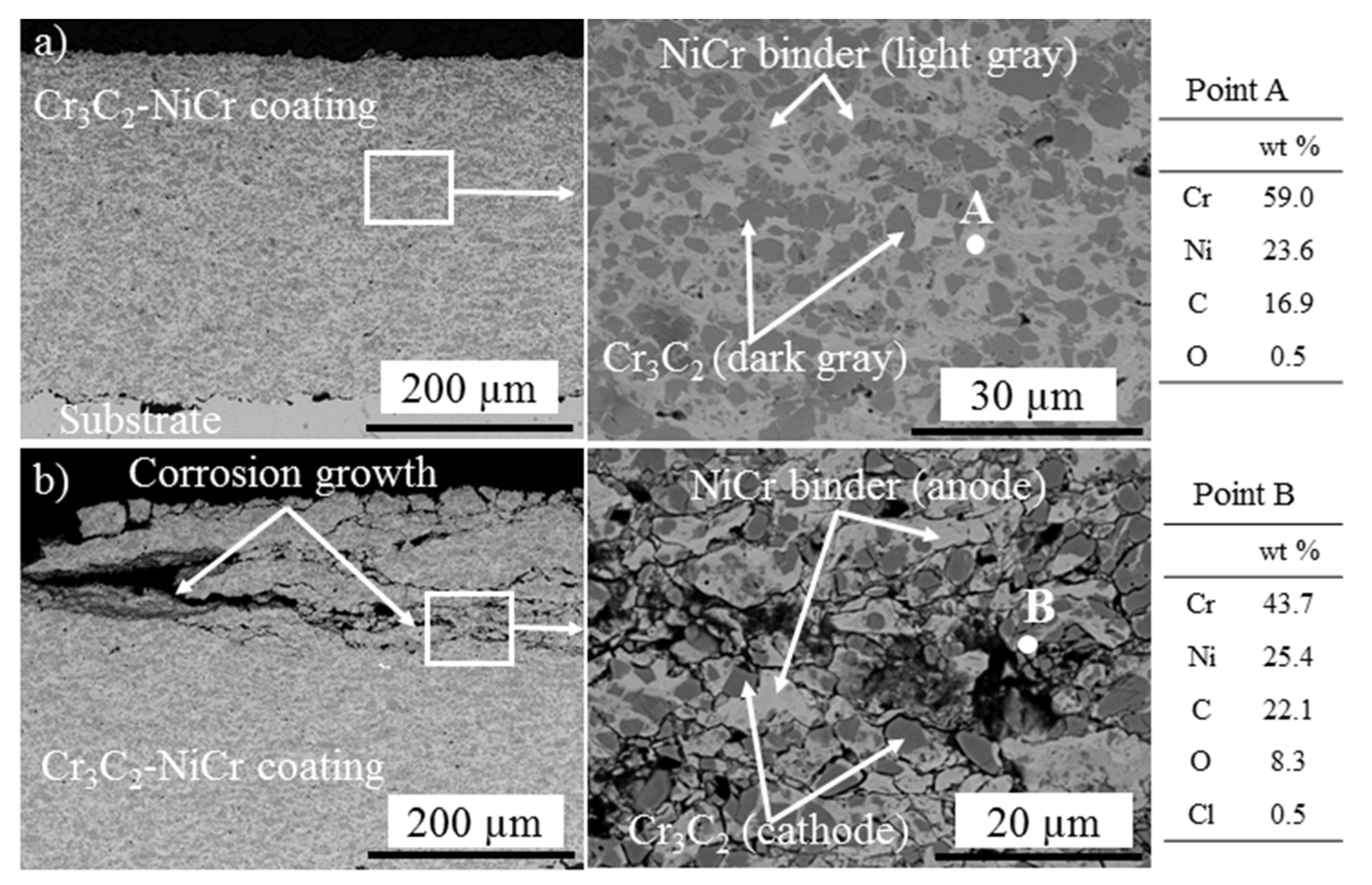
3.1.1. As-Sprayed and Corroded Cr3C2-NiCr

The SEM micrographs of the as-sprayed and corroded Cr3C2-NiCr coatings after the salt-spray test are presented in Figure 3. The as-sprayed Cr3C2-NiCr coating (Figure 3a) revealed a uniform distribution of Cr3C2 particles (dark gray) in the NiCr binder (light gray). The microstructure images and the corresponding EDS point analysis showed coatings with relatively few defects, including pores, and a negligible oxygen pick-up owing to the high velocity (700–1200 m/s) [30] and low temperature (<1800 °C) [31] of the in-flight particles in the HVAF process . No sign of splats could be seen in Figure 3a, confirming that the particles were well-splashed and plastically deformed during the HVAF process, which provided a good cohesion (particle/particle bonding). In the coating, the carbides also appeared to be well-bonded to the metal matrix. No significant sign of Cr depletion was observed after the spraying (see EDS point analysis in Figure 3a), meaning Cr could be preserved for corrosion protection. The overall content of the pores was very low (0.6 vol %) and no sign of crack formation was found in the coating. It can be confirmed that the HVAF process parameters and the powder cut size were appropriately chosen to produce dense and defect-free Cr3C2-NiCr coatings.
As already discussed, the corrosion behavior of Cr3C2-NiCr is affected by (a) porosity, (b) galvanic effect between the Cr3C2 and the NiCr metallic binder and (c) galvanic effect between the matrix zones of higher Cr3C2 concentration (subsequently lower NiCr concentration) and the matrix of higher NiCr concentration (subsequently lower Cr3C2 concentration) [4], as can be seen in Figure 3b. Based on the EDS point analysis in Figure 3b, a high amount of O and a low amount of Cl could be detected within the corrosion paths. The HVAF-sprayed Cr3C2-NiCr coating was rather dense, thus, the contribution of pores to corrosion of the coating could be critical, whereas corrosion by the galvanic pairs could be triggered throughout the coating. The NiCr was more anodic than Cr3C2, as NiCr was corroded in the couple. Therefore, the dissolution of NiCr in the galvanic couple was expected to be dominant. Conversely, the dissolution of the Cr3C2 was expected to be hindered, owing to the cathodic protection by NiCr. This means that even if there were only closed pores in the Cr3C2-NiCr coating, corrosive ions could find their paths by corroding the NiCr metallic binder and making the pores interconnected. In this context, an intermediate layer beneath the Cr3C2-NiCr coating could address the aforementioned corrosion challenges.
It could be assumed that once the electrolyte penetrates through the top layer, the corrosion resistance is associated with the electrochemical properties of the intermediate layer, mainly defined by its chemical composition and microstructure. As already discussed, corrosion of the bilayer coating could be controlled if the corrosion potential (or open-circuit potential (OCP)) of the intermediate layer would be higher than the OCP of the top layer. In the next sections, the corrosion behavior of various coatings (Ni-based and Fe-based) is studied in order to find the suitable chemistry in accordance with the corrosion behavior of the Cr3C2-NiCr coating in terms of OCP and Rp.

3.1.2. Single-Layer and Bilayer Coatings

Figure 4 presents the cross-sectional SEM micrographs of the as-sprayed Fe-based coatings produced by HVAF. The morphology of the coatings shows some degree of lamellar microstructures, with the elongated axis of the impacted splats aligned with the substrate surface. The pore content is an important factor that can affect the corrosion behavior of the thermal-spray coatings [32,33,34,35,36,37]. The porosity level was around 2.6 ± 0.2, 3.3 ± 0.5 and 3.0 ± 0.3 vol % for Fe-based 1, Fe-based 2 and Fe-based 3, respectively, confirming that the coatings were slightly porous for a typical HVAF coating.
The microhardness of Fe-based 1, Fe-based 2 and Fe-based 3 was around 951 ± 78, 691 ± 52 and 493 ± 46 HV0.3 (Microhardness Vickers), respectively. The coatings sprayed using Fe-based 1 powder reached the greatest hardness, while the coatings sprayed using Fe-based 3 powder obtained the lowest values. The high hardness of the coatings could be attributed to the formation of carbides (e.g., Cr3C2) during spraying due to the presence of C and Cr in the powder material. Moreover, high scattering (standard deviation) in the microhardness values of the coatings could be due to the presence of heterogeneities in the composition and microstructure of the coatings. Non-uniform distribution of carbides or pores along the splat boundaries could increase the microhardness scattering [4]. The non-homogeneities enhance the coatings’ sensitivity to certain types of corrosion, for example, microgalvanic corrosion [38]. The location of non-uniformities can be preferential sites for corrosion processes, as galvanic microcells are probably established between them and the metal matrix, resulting in galvanic corrosion of the matrix due to its higher tendency for corrosion [14,39,40,41].
The microstructures of HVAF-sprayed Ni, NiCr, NiAl and NiCoCrAlY coatings are shown in Figure 5. The Ni-based coatings were studied as an alternative to Fe-based coatings in order to produce denser coatings, and consequently better corrosion performance. The porosity level in coatings was measured as 0.3 ± 0.05, 0.5 ± 0.07, 0.7 ± 0.10 and 1.2 ± 0.15 vol % for the Ni, NiCr, NiAl and NiCoCrAlY coatings, respectively, verifying a less-porous microstructure of the Ni-based coatings than Fe-based coatings. Despite the use of the coarser Ni-based powders, the higher density of the Ni-based coatings obtained could be attributed to the low temperature and high velocity of in-flight particles impacting the substrate [33]. However, some coatings still presented a degree of different microstructural features, such as pores, splat boundaries and so on, which could adversely affect the corrosion behavior.
The microhardness of Ni, NiCr, NiAl, and NiCrAlY coatings was measured around 251 ± 12, 425 ± 19, 318 ± 14 and 425 ± 16 HV0.3, respectively. The lower level of scattering of the hardness values confirmed higher uniformity of the Ni-based coatings compared to the Fe-based coatings.
The electrochemical characteristics (Rp vs. OCP) of the substrate, the Cr3C2-NiCr coating and various Fe-based and Ni-based coatings studied in 3.5 wt % NaCl at room temperature are shown in Figure 6. The Ni-based coatings (apart from pure Ni) presented higher OCP values (−0.12 V/SCE for NiCoCrAlY, −0.27 V/SCE for NiCr and −0.37 V/SCE for NiAl) compared to the three Fe-based coatings (which were between −0.43 and −0.40 V/SCE), revealing that the Ni-based coatings were thermodynamically better from both composition and microstructure points of view. The low Rp and OCP values of the Fe-based coatings from the polarization test, which were most probably due to the porous microstructure (see Figure 4), confirmed that these coatings were unable to provide good corrosion protection in the corrosive environment. It was concluded that the Ni-based coatings could be used as an intermediate layer in the bilayer-coating systems, as they showed higher OCP values.
The electrochemical characteristics of the bilayer coatings with the Ni-based intermediate layers are shown in Figure 6. The higher OCP values of the NiCoCrAlY and NiCr layers (than that of the top layer Cr3C2-NiCr) impede the passing through of the electrolyte from the top layer to the intermediate layer [4], whereas in the NiAl intermediate layer, the OCP was lower than that of Cr3C2-NiCr. In the former situation, the intermediate layer would be sacrificially protected by the top layer, thus, in case of failure in Cr3C2-NiCr, the intermediate layer still serves as a corrosion barrier. In the latter, once the electrolyte reaches the intermediate layer/top layer interface, the intermediate layer corrodes, which eventually permits the electrolyte to further penetrate and reach the substrate. Figure 6 also shows that the pure Ni coating cannot properly fulfil the requirements of an intermediate layer and protect the bilayer coating against corrosion, as its OCP was considerably lower than that of Cr3C2-NiCr. Higher differences between the OCP values increase the level of the galvanic corrosion once the electrolyte is present [4].
According to Figure 6, the NiCr coating showed a more positive OCP value compared to the NiAl coating, verifying that the chromia-forming coating could reveal a better protection of the substrate than the alumina-forming coating. The high corrosion protection of the NiCoCrAlY coating was most probably due to its more homogeneous alloy composition without sites for forming macrogalvanic cells.
The bilayer NiCoCrAlY/Cr3C2-NiCr coating showed the highest Rp. Considering the values of OCP and Rp, the NiCoCrAlY/Cr3C2-NiCr system showed superior corrosion resistance than the other coatings.
The SEM images (Figure 7) show that the electrolyte penetrated through the interconnected pores of the Cr3C2-NiCr top layer and reached the top/intermediate layer interface when Ni and NiAl were used as the intermediate layers. The corrosive ions even penetrated through Ni and NiAl, as these intermediate layers provided lower OCP than that of Cr3C2-NiCr, whereas NiCoCrAlY did not show any sign of corrosion.
It was found that although the Ni coatings presented a better splat cohesion and lower porosity compared to the other intermediate layers (Figure 5), pure Ni itself was not inherently able to last in 3.5 wt % NaCl [42]. The NiCoCrAlY intermediate layer did not show a perfect coating in terms of density compared to pure Ni. However, the coating systems containing the NiCoCrAlY intermediate layer presented better corrosion resistance than the NiCr/Cr3C2-NiCr or Ni/Cr3C2-NiCr ones. As the top layer/intermediate layer interface acted as an additional barrier to avoid the corrosion of the substrate, the electrolyte failed to penetrate easily through the splat boundaries of the intermediate layer. Formation of galvanic cells between the substrate and intermediate layers was also facilitated, as Cr3C2-NiCr was more anodic than, for instance, the NiCoCrAlY intermediate layer (based on the OCP measurements shown in Figure 6). Therefore, if the electrolyte meets the intermediate layer through the defects of the top layer, the intermediate layer is sacrificially protected by the top layer (see Figure 7).
NiCr was unable to tolerate the corrosive environment, not only because of the low corrosion resistance of Ni, but also due to a great number of microgalvanic cells that formed between Ni and alloying elements like Cr in the corresponding coatings. In the NiCoCrAlY coating, the presence of two phases (γ-NiCoCr and β-NiAl), which most probably had Ecorr (or OCP) close to each other, resulted in corrosion propagation through the splat boundaries around a single NiCoCrAlY particle. Therefore, the high corrosion protection by the NiCoCrAlY coating could be due to the homogeneous alloy composition, without formation of macrogalvanic cells [43].
It was also reported that Cr and Al could form a thin passive layer to control the corrosion [44]. A less-porous coating, as obtained in this study using the HVAF process, allows Cr and Al to easily diffuse further to the corrosion front where the passive film is supposed to form. Consistent with the OCP results, the simultaneous addition of Cr and Al to Ni-based coatings provided a more cathodic intermediate layer (higher OCP), which was highly beneficial for the bilayer coating with the Cr3C2-NiCr top layer. The composition of the NiCoCrAlY coating encouraged the formation of the γ-NiCoCr and β-NiAl phases and also defects within the coating (which develop the pitting) [33]. However, full support of the passive layer by Cr and Al together compromised the effect of the coatings’ defects and undesired galvanic couples.

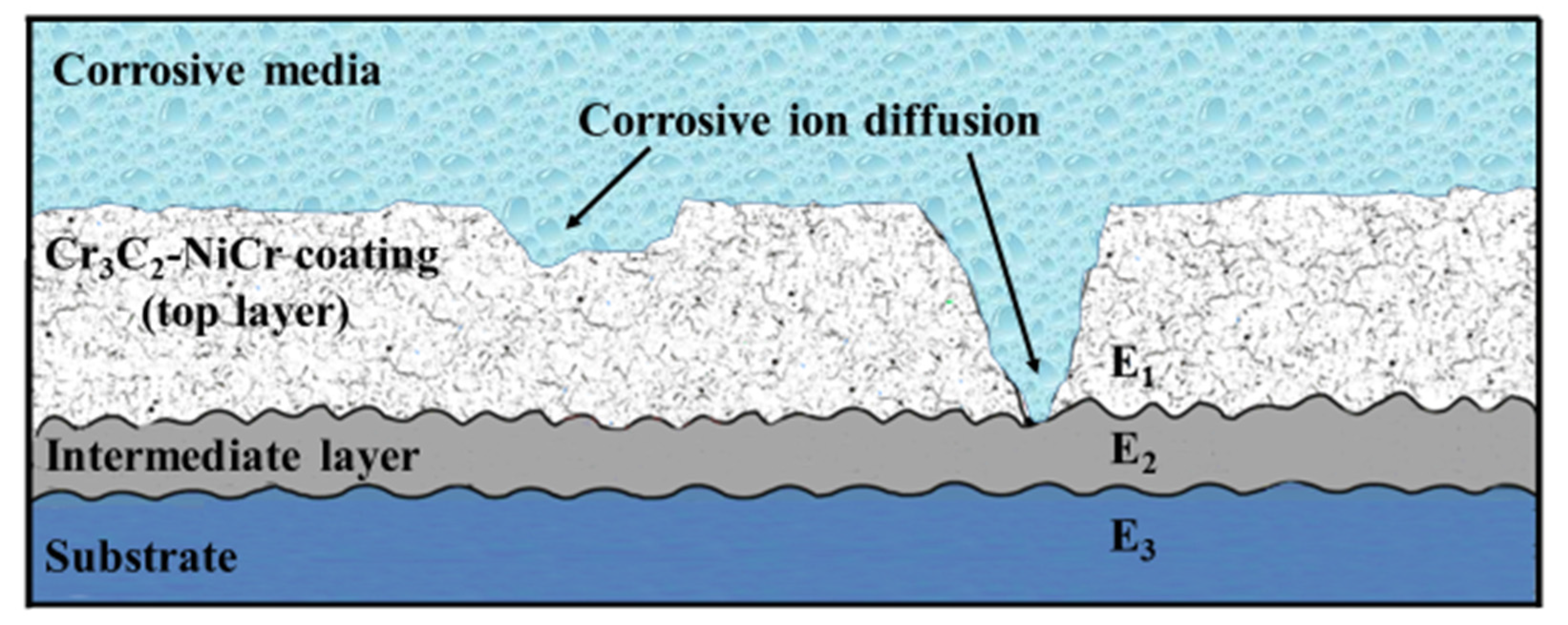
3.2. Proposed Corrosion Mechanism

Figure 8 shows schematic views of the bilayer coatings with different configurations in terms of galvanic coupling between the top and intermediate layers. As illustrated in both cases, the OCP (or Ecorr) of the intermediate layer affects the corrosion behavior of the bilayer coatings. The OCP values are affected by composition and microstructure of the coatings [17]. The presence of some coating features—for example, pores, splat boundaries or in in situ oxides-reduce the OCP values, whereas Ni rather than Fe or addition of passive layer-forming elements—for example, Cr or/and Al—provide high OCP values. The severity of corrosion in a bilayer coating depends on the magnitude of the potential difference between the top and intermediate layers, defined by Equation (2):
E ( or   OCP ) = OCP intermediate   layer OCP top   layer
Higher OCPintermediate layer than OCPtop layer ensures that the intermediate layer is sacrificially protected by the top layer, therefore, the lifetime of the coating system will be longer. The values in Figure 6 show that the OCP of the NiCoCrAlY layer was significantly higher than that of the top Cr3C2-NiCr layer, leading to very high corrosion resistance (Rp) of the bilayer coating. The difference is lower in the case of NiCr and Cr3C2-NiCr, confirming the lower corrosion resistance of the bilayer NiCr/Cr3C2-NiCr coating. The OCP of Ni and NiAl was lower than that of Cr3C2-NiCr, leading to the failure in the corresponding bilayer coatings, as seen in Figure 7.

4. Summary

The corrosion behavior of various Fe-based and Ni-based bilayer coatings sprayed with an HVAF process has been investigated. The main findings could be summarized as follows:
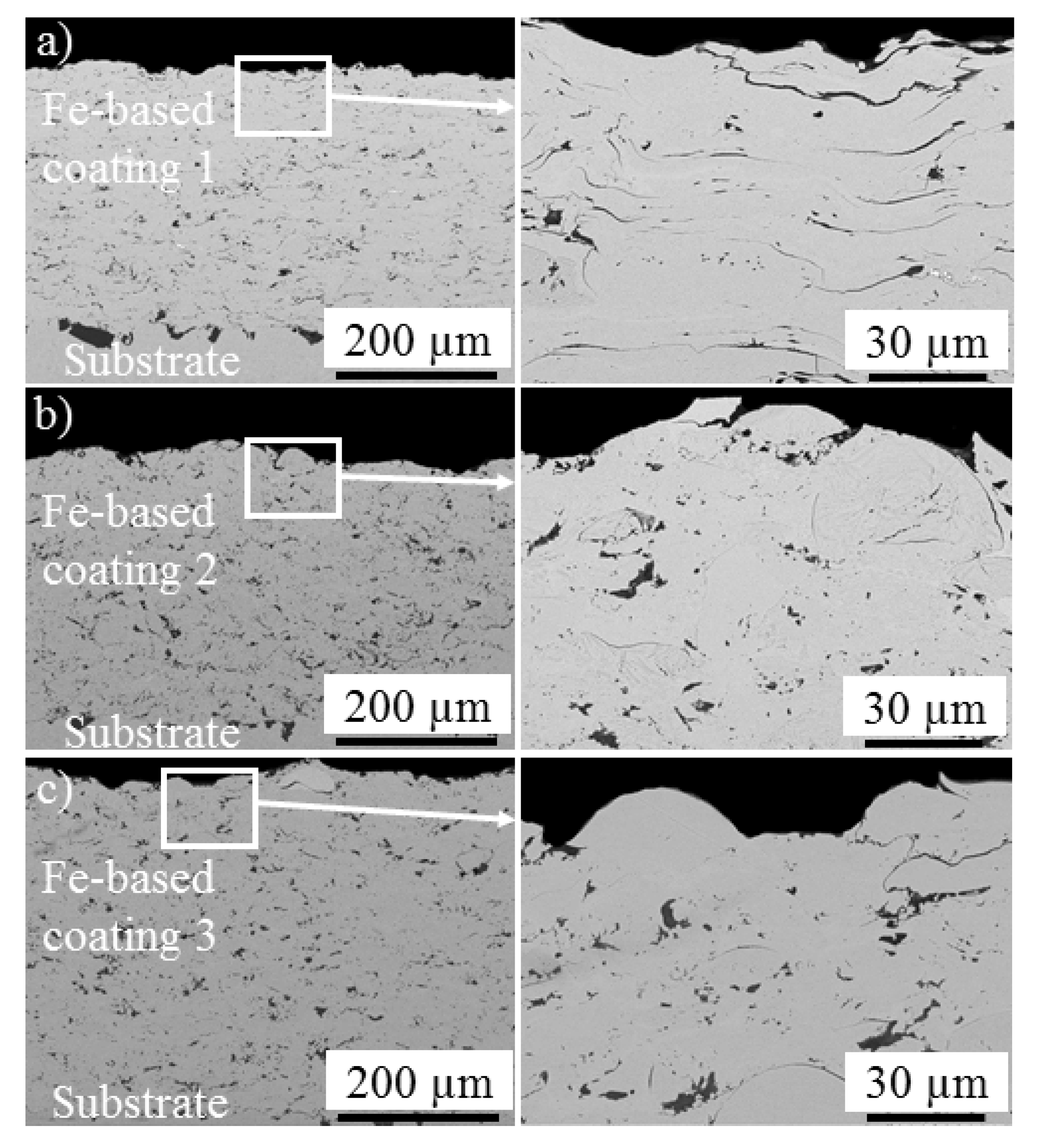
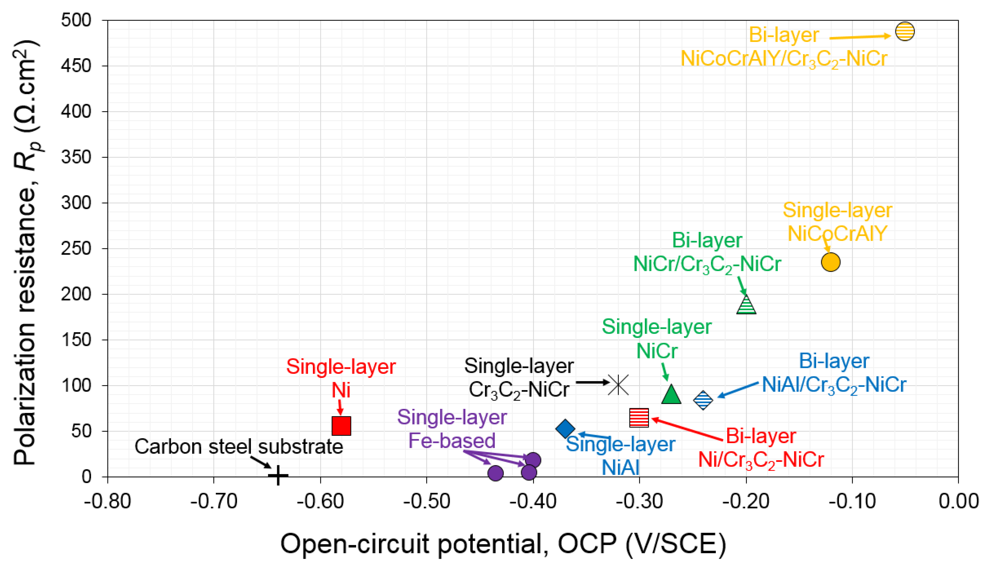
  • While high-alloyed Fe-based coatings showed rather porous structures, the corrosion results of all the three coatings showed low Rp as well as low OCP. The study was directed towards the Ni-based coatings, as the Fe-based coatings were unable to provide higher Rp and OCP values.
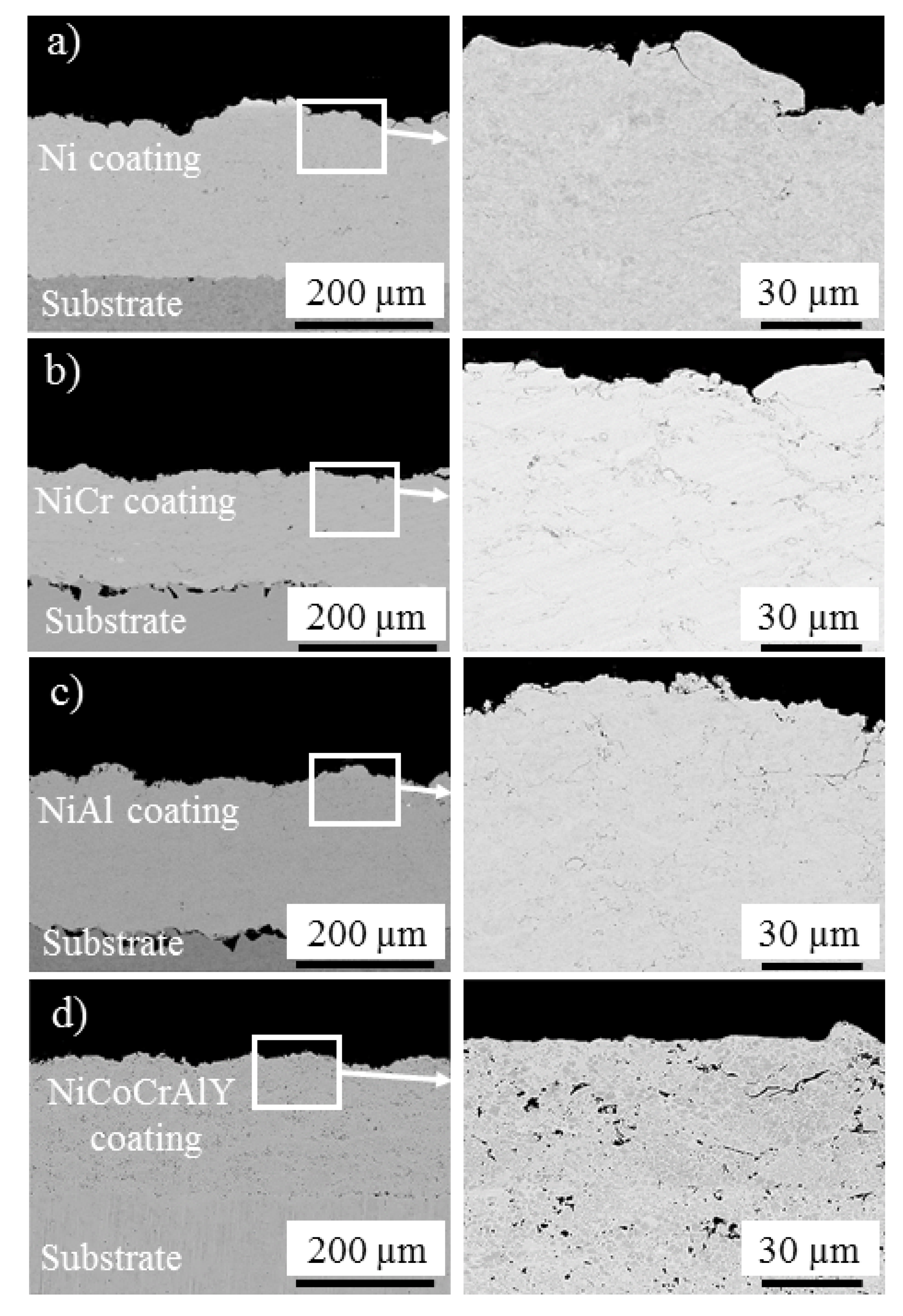
  • Ni-based coatings showed high electrochemical values (Rp and OCP) while having a sufficient level of the passive layer-forming elements, for example, Cr or/and Al. The particles were well-splashed and deformed over each other during the spraying process, and thus the level of porosity was very low.
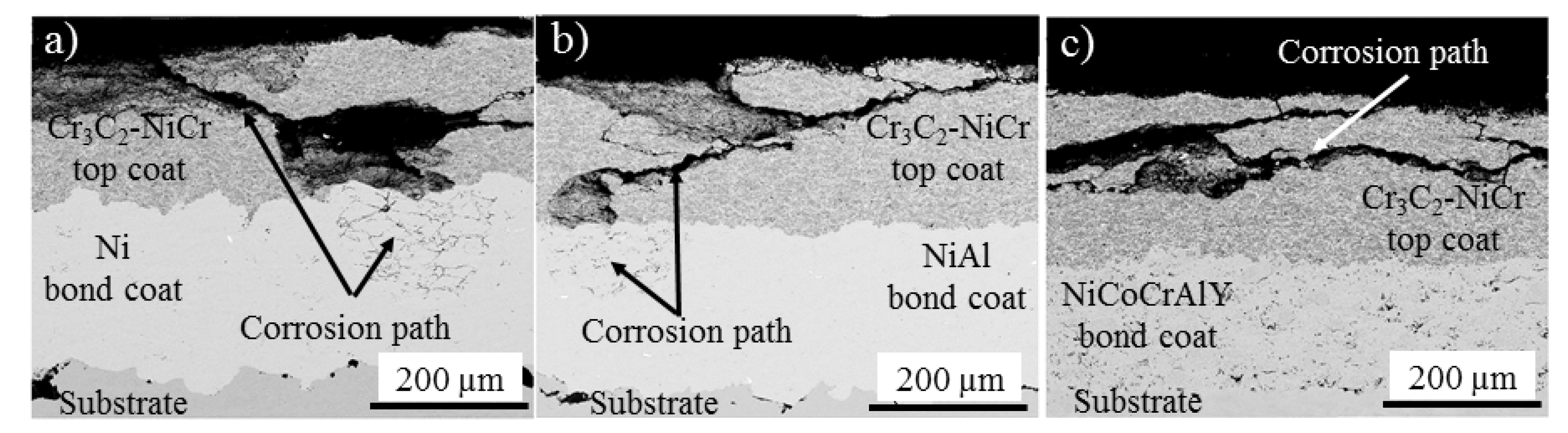
  • The OCP of the intermediate layers determined the corrosion behavior of the bilayer coating. Higher OCP of the intermediate layer than that of the top layer led to a galvanic couple which favored the intermediate layer to be sacrificially protected. In this situation, diffusion of corrosive ions was stopped at the intermediate/top layer interface.
  • Both microstructure and chemical composition of the intermediate layer affected the corrosion resistance of the bilayer coatings. The chemical composition had higher contribution to corrosion protection; however, the effect of defects in thermal-spray coatings cannot be neglected.
  • Addition of alloying elements such as Cr or Al improved the corrosion behavior of the pure Ni coating. The NiCr or NiCoCrAlY coatings presented higher content of defects, but better corrosion behavior, than the denser Ni coating.
  • The most promising coating system used was a Cr3C2-NiCr top layer with an intermediate layer of NiCoCrAlY. However, corrosion protection in the NiCr/Cr3C2-NiCr design could be more economically favored for industrial applications.

Acknowledgments

Financial support of Västra Götalands Regionen (VGR) for the PROSAM project (RUN 2016-01489) is highly acknowledged. The authors would like to thank Jonas Olsson and Stefan Björklund for spraying the coatings and Kenneth Andersson for his help in characterizing the coatings.

Author Contributions

Esmaeil Sadeghimeresht and Nicolaie Markocsan conceived and designed the experiments; Esmaeil Sadeghimeresht performed the experiments, analyzed the data and contributed reagents/materials/analysis tools; Esmaeil Sadeghimeresht and Nicolaie Markocsan wrote the paper.

Conflicts of Interest

The authors declare no conflict of interest.

References

  1. Sadeghimeresht, E.; Markocsan, N.; Nylén, P. A comparative study of corrosion resistance for HVAF-sprayed Fe- and Co-based coatings. Coatings 2016, 6, 16. [Google Scholar] [CrossRef]
  2. Picas, J.A.; Forn, A.; Igartua, A.; Mendoza, G. Mechanical and tribological properties of high velocity oxy-fuel thermal sprayed nanocrystalline CrC-NiCr coatings. Surf. Coat. Technol. 2003, 174, 1095–1100. [Google Scholar] [CrossRef]
  3. Murthy, J.K.N.; Venkataraman, B. Abrasive wear behaviour of WC–CoCr and Cr3C2–20(NiCr) deposited by HVOF and detonation spray processes. Surf. Coat. Technol. 2006, 200, 2642–2652. [Google Scholar] [CrossRef]
  4. Sadeghimeresht, E.; Markocsan, N.; Nylén, P.; Björklund, S. Corrosion performance of bi-layer Ni/Cr2C3-NiCr HVAF thermal spray coating. Appl. Surf. Sci. 2016, 369, 470–481. [Google Scholar] [CrossRef]
  5. Guilemany, J.M.; Espallargas, N.; Fernández, J.; Suegama, P.H.; Benedetti, A.V. High-velocity oxyfuel Cr3C2-NiCr replacing hard chromium coatings. J. Therm. Spray Technol. 2005, 14, 335–341. [Google Scholar] [CrossRef]
  6. Guilemany, J.M.; Espallargas, N.; Suegama, P.H.; Benedetti, A.V. Comparative study of Cr3C2-NiCr coatings obtained by HVOF and hard chromium coatings. Corros. Sci. 2006, 48, 2998–3013. [Google Scholar] [CrossRef]
  7. Toma, D.; Brandl, W.; Marginean, G. Wear and corrosion behaviour of thermally sprayed cermet coatings. Surf. Coat. Technol. 2001, 138, 149–158. [Google Scholar] [CrossRef]
  8. Suegama, P.H.; Fugivara, C.S.; Benedetti, A.V.; Fernández, J.; Delgado, J.; Guilemany, J.M. Electrochemical behaviour of thermally sprayed Cr3C2-NiCr coatings in 0.5 M H2SO4 media. J. Appl. Electrochem. 2002, 32, 1287–1295. [Google Scholar] [CrossRef]
  9. Suarez, M.; Bellayer, S.; Traisnel, M.; Gonzalez, W.; Chicot, D.; Lesage, J.; Puchi-Cabrera, E.S.; Staia, M.H. Corrosion behavior of Cr3C2-NiCr vacuum plasma sprayed coatings. Surf. Coat. Technol. 2008, 202, 4566–4571. [Google Scholar] [CrossRef]
  10. Poza, P.; Múnez, C.J.; Garrido-Maneiro, M.A.; Vezzù, S.; Rech, S.; Trentin, A. Mechanical properties of Inconel 625 cold-sprayed coatings after laser remelting. Depth sensing indentation analysis. Surf. Coat. Technol. 2014, 243, 51–57. [Google Scholar] [CrossRef]
  11. García-Rodríguez, S.; López, A.J.; Torres, B.; Rams, J. 316L stainless steel coatings on ZE41 magnesium alloy using HVOF thermal spray for corrosion protection. Surf. Coat. Technol. 2016, 287, 9–19. [Google Scholar] [CrossRef]
  12. Campo, M.; Carboneras, M.; lópez, M.D.; Torres, B.; Rodrigo, P.; Otero, E.; Rams, J. Corrosion resistance of thermally sprayed Al and Al/SiC coatings on Mg. Surf. Coat. Technol. 2009, 203, 3224–3230. [Google Scholar] [CrossRef]
  13. Suegama, P.H.; Fugivara, C.S.; Benedetti, A.V.; Guilemany, J.M.; Fernández, J.; Delgado, J. The influence of gun transverse speed on electrochemical behaviour of thermally sprayed Cr3C2-NiCr coatings in 0.5 M H2SO4 solution. Electrochim. Acta 2004, 49, 627–634. [Google Scholar] [CrossRef]
  14. Lekatou, A.; Zois, D.; Karantzalis, A.E.; Grimanelis, D. Electrochemical behaviour of cermet coatings with a bond coat on Al7075: Pseudopassivity, localized corrosion and galvanic effect considerations in a saline environment. Corros. Sci. 2010, 52, 2616–2635. [Google Scholar] [CrossRef]
  15. Chatha, S.S.; Sidhu, H.S.; Sidhu, B.S. Characterisation and corrosion-erosion behaviour of carbide based thermal spray coatings. J. Miner. Mater. Charact. Eng. 2012, 11, 569. [Google Scholar] [CrossRef]
  16. Bolelli, G.; Cannillo, V.; Lusvarghi, L.; Rosa, R.; Valarezo, A.; Choi, W.B.; Dey, R.; Weyant, C.; Sampath, S. Functionally graded WC–Co/NiAl HVOF coatings for damage tolerance, wear and corrosion protection. Surf. Coat. Technol. 2012, 206, 2585–2601. [Google Scholar] [CrossRef]
  17. Sadeghimeresht, E.; Markocsan, N.; Nylén, P. Microstructural and electrochemical characterization of Ni-based bi-layer coatings produced by the HVAF process. Surf. Coat. Technol. 2016, 304, 606–619. [Google Scholar] [CrossRef]
  18. Godoy, C.; Lima, M.M.; Castro, M.M.R.; Avelar-Batista, J.C. Structural changes in high-velocity oxy-fuel thermally sprayed WC–Co coatings for improved corrosion resistance. Surf. Coat. Technol. 2004, 188–189, 1–6. [Google Scholar] [CrossRef]
  19. Kuroda, S.; Kawakita, J.; Fukushima, T.; Tobe, S. Importance of the adhesion of HVOF sprayed coatings for aqueous corrosion resistance. Mater. Trans. 2003, 44, 381–388. [Google Scholar] [CrossRef]
  20. Bergant, Z.; Trdan, U.; Grum, J. Effect of high-temperature furnace treatment on the microstructure and corrosion behavior of NiCrBSi flame-sprayed coatings. Corros. Sci. 2014, 88, 372–386. [Google Scholar] [CrossRef]
  21. Bao, Z.B.; Wang, Q.M.; Li, W.Z.; Gong, J.; Xiong, T.Y.; Sun, C. Corrosion behaviour of AIP NiCoCrAlYSiB coating in salt spray tests. Corros. Sci. 2008, 50, 847–855. [Google Scholar] [CrossRef]
  22. Bolelli, G.; Börner, T.; Milanti, A.; Lusvarghi, L.; Laurila, J.; Koivuluoto, H.; Niemi, K.; Niemi, P. Tribological behavior of HVOF- and HVAF-sprayed composite coatings based on Fe-Alloy + WC–12% Co. Surf. Coat. Technol. 2014, 248, 104–112. [Google Scholar] [CrossRef]
  23. Sadeghimeresht, E.; Markocsan, N.; Nylén, P. Microstructural characteristics and corrosion behavior of HVAF- and HVOF-sprayed Fe-based coatings. Surf. Coat. Technol. 2017, 318, 365–373. [Google Scholar] [CrossRef]
  24. Sadeghimeresht, E.; Markocsan, N.; Nylén, P. A comparative study on Ni-based coatings prepared by HVAF, HVOF, and APS methods for corrosion protection applications. J. Therm. Spray Technol. 2016, 25, 1604–1616. [Google Scholar] [CrossRef]
  25. Sadeghimeresht, E.; Markocsan, N.; Huhtakangas, M.; Joshi, S. Isothermal oxidation of HVAF-sprayed Ni-based chromia, alumina and mixed-oxide scale forming coatings in ambient air. Surf. Coat. Technol. 2017, 316, 10–21. [Google Scholar] [CrossRef]
  26. ASTM B117-16 Standard Practice for Operating Salt Spray (Fog) Apparatus; ASTM International: West Conshohocken, PA, USA, 2016.
  27. Milanti, A.; Matikainen, V.; Koivuluoto, H.; Bolelli, G.; Lusvarghi, L.; Vuoristo, P. Effect of spraying parameters on the microstructural and corrosion properties of HVAF-sprayed Fe-Cr-Ni-B-C coatings. Surf. Coat. Technol. 2015, 277, 81–90. [Google Scholar] [CrossRef] [Green Version]
  28. Schneider, C.A.; Rasband, W.S.; Eliceiri, K.W. NIH Image to ImageJ: 25 years of image analysis. Nat. Methods 2012, 9, 671–675. [Google Scholar] [CrossRef] [PubMed]
  29. ASTM E384-11e1 Standard Test Method for Knoop and Vickers Hardness of Materials; ASTM International: West Conshohocken, PA, USA, 2011.
  30. Sadeghimeresht, E.; Markocsan, N.; Nylén, P. Microstructure effect of intermediate coat layer on corrosion behavior of HVAF-sprayed bi-layer coatings. J. Therm. Spray Technol. 2017, 26, 243–253. [Google Scholar] [CrossRef]
  31. Zeng, Z.; Sakoda, N.; Tajiri, T.; Kuroda, S. Structure and corrosion behavior of 316L stainless steel coatings formed by HVAF spraying with and without sealing. Surf. Coat. Technol. 2008, 203, 284–290. [Google Scholar] [CrossRef]
  32. Zhao, W.-M.; Wang, Y.; Dong, L.-X.; Wu, K.-Y.; Xue, J. Corrosion mechanism of NiCrBSi coatings deposited by HVOF. Surf. Coat. Technol. 2005, 190, 293–298. [Google Scholar] [CrossRef]
  33. Sadeghimeresht, E.; Hooshyar, H.; Markocsan, N.; Joshi, S.; Nylén, P. Oxidation behavior of HVAF-sprayed NiCoCrAlY coating in H2–H2O environment. Oxid. Met. 2016, 86, 299–314. [Google Scholar] [CrossRef]
  34. Sadeghimeresht, E.; Markocsan, N.; Joshi, S. Isothermal oxidation behavior of HVAF-sprayed Ni and NiCr coatings in H2-H2O environment. Surf. Coat. Technol. 2017, 317, 17–25. [Google Scholar] [CrossRef]
  35. Sadeghimeresht, E.; Markocsan, N.; Nylén, P. HVAF thermal spray Fe-based coating : An environmentally acceptable alternative to cobalt-based coating. In Proceedings of the EuroCorr 2015, European Corrosion Congress, Graz, Austria, 6–10 September 2015. [Google Scholar]
  36. Clement, C.; Sadeghimeresht, E.; Lyphout, C.; Markocsan, N.; Nylén, P. Corrosion behavior of HVAF- and HVOF-sprayed high-chromium Fe-based coatings. In Proceedings of the 7th Rencontres Internationales sur la Projection Thermique, Limoges, France, 9–11 December 2015. [Google Scholar]
  37. Sadeghimeresht, E.; Markocsan, N.; Nylén, P.; Dizdar, S. Corrosion behavior of high-chromium Fe-based coatings produced by HVAF thermal spraying technique. In Proceedings of the 7th Rencontres Internationales sur la Projection Thermique, Limoges, France, 9–11 December 2015. [Google Scholar]
  38. Milanti, A.; Koivuluoto, H.; Vuoristo, P. Influence of the spray gun type on microstructure and properties of HVAF sprayed fe-based corrosion resistant coatings. J. Therm. Spray Technol. 2015, 24, 1312–1322. [Google Scholar] [CrossRef]
  39. Xu, C.; Du, L.; Yang, B.; Zhang, W. The effect of Al content on the galvanic corrosion behaviour of coupled Ni/graphite and Ni-Al coatings. Corros. Sci. 2011, 53, 2066–2074. [Google Scholar] [CrossRef]
  40. Lekatou, A.; Regoutas, E.; Karantzalis, A.E. Corrosion behaviour of cermet-based coatings with a bond coat in 0.5 M H2SO4. Corros. Sci. 2008, 50, 3389–3400. [Google Scholar] [CrossRef]
  41. Verdian, M.M.; Raeissi, K.; Salehi, M. Corrosion performance of HVOF and APS thermally sprayed NiTi intermetallic coatings in 3.5% NaCl solution. Corros. Sci. 2010, 52, 1052–1059. [Google Scholar] [CrossRef]
  42. Hoffmeister, H. Modeling of crevice corrosion of pure nickel by coupling of phase and polarization behavior at various pH, chloride, and oxygen levels. Corrosion 2005, 61, 880–888. [Google Scholar] [CrossRef]
  43. Fan, X.; Zou, B.; Gu, L.; Wang, C.; Wang, Y.; Huang, W.; Zhu, L.; Cao, C. Investigation of the bond coats for thermal barrier coatings on Mg alloy. Appl. Surf. Sci. 2013, 265, 264–273. [Google Scholar] [CrossRef]
  44. Guilemany, J.M.; Cinca, N.; Dosta, S.; Benedetti, A.V. Corrosion behaviour of thermal sprayed nitinol coatings. Corros. Sci. 2009, 51, 171–180. [Google Scholar] [CrossRef]
Figure 1. Initiation and growth of corrosion in a typical Cr3C2-NiCr coating through (a) interconnected porosity, and (b) metallic binder.
Coatings 07 00162 g001
Figure 2. Schematic view of the bilayer coating [4]. (Reproduced from [4] with permission; Copyright 2016 Elsevier). E1 = corrosion potential of the top layer, E2 = corrosion potential of the intermediate layer, and E3 = corrosion potential of the substrate.
Coatings 07 00162 g002
Figure 3. SEM back-scattered micrograph of cross-section of the (a) as-sprayed Cr3C2-NiCr coating, (b) corrosive ion penetration paths, cathodic and anodic sites within the Cr3C2-NiCr coating after salt-spray test at 24 °C for 240 h, and the corresponding EDS point analysis.
Coatings 07 00162 g003
Figure 4. Back-scattered SEM micrographs of cross-sections of as-sprayed (a) Fe-based 1, (b) Fe-based 2 and (c) Fe-based 3.
Coatings 07 00162 g004
Figure 5. Back-scattered SEM micrographs of cross-sections of HVAF-sprayed Ni-based coatings: (a) Ni, (b) NiCr, (c) NiAl and (d) NiCoCrAlY.
Coatings 07 00162 g005
Figure 6. Polarization resistance (Rp) vs. open-circuit potential (OCP) of various HVAF single- and bilayer coatings in 3.5 wt % NaCl solution.
Coatings 07 00162 g006
Figure 7. Microstructure of the corroded samples, (a) Ni/Cr3C2-NiCr, (b) NiAl/Cr3C2-NiCr and (c) NiCoCrAlY/Cr3C2-NiCr [17]. (Reproduced from [17] with permission; Copyright 2016 Elsevier).
Coatings 07 00162 g007
Figure 8. Schematic view of bilayer coatings with different configurations, (a) OCP of the top layer is higher than that of the intermediate layer, and (b) OCP of the intermediate layer is higher than OCP of the top layer. E1 = corrosion potential of the top layer, E2 = corrosion potential of the intermediate layer, and E3 = corrosion potential of the substrate.
Coatings 07 00162 g008
Table 1. Chemical composition and particle-size distribution of the powders.
No.PowderChemical Composition (wt %)Powder Size (µm)
NiAlCrOCCoMoFe
1Fe-based 111.0300.20.6Bal.36 ± 20
2Fe-based 217.0280.11.84.5Bal.36 ± 20
3Fe-based 34.0100.22.05.5Bal.36 ± 20
4Ni (Amperit® 176.001)Bal.0.145 ± 22
5NiCr (Amperit® 251.071)Bal.21.10.145 ± 22
6NiAl (Amperit® 281.003)Bal.5.50.145 ± 5
7NiCoCrAlY (AMDRY 386-0)Bal.8.5200.223.163 ± 5
8Cr3C2-NiCr 75/25 (Amperit® 584.054)20.5Bal.0.38.945 ± 22
Table 2. HVAF process parameters.
ParameterFe-Based 1Fe-Based 2Fe-Based 3NiNiCrNiAlNiCoCrAlYCr3C2-NiCr
Nozzle3L2G3L2G3L2G4L44L43L24L24L2
Spray distance (mm)400400400350300350350350
Gun traverse velocity (m/min)100100100100100100100100
Powder-feed rate (g/min)10010010015050150150150
Nitrogen carrier gas flow (L/min)6060606060606060
Air pressure (MPa)0.80.80.80.820.820.80.80.8
Fuel 1 (propane) pressure (MPa)0.690.690.690.70.690.660.650.7
Fuel 2 (propane) pressure (MPa)0.690.690.690.70.690.700.650.7

