1. Introduction
The properties of a substrate metal can be altered through the use of surface coatings as part of the metal finishing process. These alterations may be to improve decorative or functional aspects of the substrate such as physical aesthetics, improved chemical resistance, or even improved mechanical properties. Surface coatings which range from nanometre to micrometre thicknesses can be achieved through physical or even chemical thin film deposition methods. Although the outcome of both methods will result in a thin film being deposited on the substrate layer, physical deposition methods utilise mechanical, electromagnetic, or thermodynamic phenomena, while chemical deposition typically involves using a fluid or gaseous precursor [
1,
2,
3].
Electroplating is a high-performance, low-cost method of chemical deposition that is commercially viable and can be used in a wide variety of applications, from improving the aesthetics of a substrate to depositing semiconductors for electronics [
4]. Silver is a metal that can be electroplated to provide desirable properties, such as being a good conductor of electricity, chemically stable in being able to resist corrosion, and even being able to provide tribological (tribology can be defined as a branch of mechanical engineering and materials science involving the study and application of principles involving friction, lubrication and wear between moving surfaces) improvements [
5,
6,
7,
8,
9]. From a cost perspective, the price of silver is approximately 65 times cheaper than gold per ounce. Its lower cost makes it a more commercial proposition in metal finishing, resulting in usages of more than 50 times that of gold. Recent research has also highlighted the benefits of silver for various consumer and medical applications due to its anti-bacterial properties and biocompatibility [
5,
10].
Although traditional cyanide silver plating is typically associated with having detrimental effects to the environment, it is able to offer a consistent plating quality at the lowest cost [
11]. It was only in the 20th century that cyanide alternatives to silver electroplating were able to produce mirror bright and ductile surface finishes adhering sufficiently to the substrates upon which the silver film is being deposited [
12]. Cyanide alternatives to silver electroplating include inorganic complexes and organic complexes such as ammonium hydroxide, thiorea, succinimide, and methanesulfonic acids [
11,
12,
13]. Although initial attempts at eliminating cyanide from silver electroplating had failed to meet the quality of surface finish produced by a cyanide bath, later successes were found in the use of inorganic complex thiosulfate and organic complex succinimide, which have been successfully adopted for selective commercial uses [
14].
One of the main issues with cyanide alternatives to silver plating is poor adhesion without prior processing using a suitable strike [
14]. In electroplating terms, strikes are special, micrometre thin plating deposits of a compatible metal that will serve as a foundation between the subsequent plating process and the substrate metal. Morrissey and Blair have independently reported poor quality of deposits obtained from organic complexes (i.e., due to tarnishing), compared to the quality of deposits obtained from cyanide electrolytes [
11,
14]. These reported attempts at finding a cyanide alternative to silver electroplating along with the continued use of silver cyanide solutions in recent research [
9,
15] provide evidence to support the fact that although cyanide alternatives are available, there is not a like-for-like replacement for cyanide in silver electroplating, and cyanide alternatives are tailored to individual applications.
Electrodeposition may be carried out using the direct current method, pulsed current, or even pulsed reverse current methods. Among these methods, the direct current (DCP) method is by far the simplest method of electrodeposition through the application of direct current and potential in an electroplating bath. Pulsed electrodeposition (PED), on the other hand, is the swift alternating of current between two different values to create a series of pulses which are typically of equal amplitude, polarity, and duration that is separated by zero current [
16,
17,
18]. PED can either be achieved through pulsed current methods, often denoted pulsed plating (PCP) or pulsed reverse current methods, and often denoted pulsed reverse plating (PRP). The benefits of PED over DCP include that of improved throwing power, smaller grain sizes, reduced porosity, increased hardness, and better ductility [
19,
20].
Research on the incorporation of dispersed foreign particles in a metallic matrix composite (MMC) started in 1928, with the co-deposition of copper and graphite [
21]. Since then, research into the incorporation of finely dispersed particles into a MMC has been extensively carried out [
22,
23,
24,
25,
26,
27,
28,
29,
30,
31,
32,
33,
34,
35,
36]. Variables that affect particle incorporation include current density, pH and bath composition, hydrodynamics and particle size, type, and shape [
37,
38,
39,
40,
41,
42]. Based on reviews of particle incorporation into MMCs, Walsh et al. [
43] state that it is possible to incorporate chemically inert but hydrophobic polytetrafluoroethene (PTFE) particles with parameters such as particle size, surfactant type, and concentration being critical in obtaining high particle incorporation rates in the metal matrix through a stable plating bath; however, they also point out that the difficulty of obtaining PTFE suspension compatibility with the bath due to the cationic surfactants, alcoholic, or aqueous liquid used. Furthermore, particle sizes should conform to an upper limit of 40 µm. Successful attempts at co-deposition of inert particles are claimed through work carried out by Helle et al. in the late 20th century, which also included the incorporation of PTFE through surfactant-containing baths into various metals, including copper, nickel, and silver [
44,
45,
46,
47].
Particles can be incorporated into a MMC through several methods, such as electrophoretic movement of charged particles during the electrodeposition, convection of particles towards the cathode surface, or even mechanical entrapment of particles in the growing MMC [
43]. It is not uncommon for several of these incorporation methods to occur at the same time. To get high rates of incorporation for the dispersed particles, methods such as the use of high nanoparticle concentrations in the electrolyte solution, smaller sized nanoparticles, low concentration of electroactive species, the use of ultrasonification during deposition, and even the use of PED can be used [
22,
48]. When compared to DC plating, PED yields nanocrystalline coatings with improved surface appearance and properties, such as smoothness, refined grains, and enhanced corrosion resistance [
23,
49,
50,
51,
52,
53]. PED currents can either be on–off (unipolar) or even reversed (bipolar), used alone or superimposed on a DC feed [
48].
The PED process offers more control over parameters which can be adjusted independently and can withstand much higher instantaneous current densities [
54]. PED affects the structure of deposited metal or coating by influencing the interplay between nucleation and crystal growth as part of the electrocrystallisation process [
55]. The application of a periodically changing current can be used to control these two aforementioned processes.
There are four variable parameters which are critical to PCP. These are peak current density, average current density, interval time, and pulse time; with one pulse cycle being a total of the interval and pulse time [
56]. Control of the pulse cycles—specifically the pulse time, where current is applied—is crucial in the success of the PCP process [
42]. During the pulse time, an evenly distributed ion concentration is available for deposition. On the other hand, during the interval time, metal ions from the bulk solution are able to diffuse into the layer next to the anode [
18]. By varying these critical parameters, the microstructure and properties of the deposited thin films can be controlled [
20,
57].
Our previous study focused on identifying the best DCP parameters for a non-cyanide Ag–PTFE electrodeposition [
58] which resulted in tribological improvements over silver DCP using the same process. As the next phase of the research, we report our attempts at the continued development of a self-lubricating Ag–PTFE MMC coating which improves on existing self-lubrication properties of silver coatings produced using environmentally-friendly silver electroplating techniques. The aim of this paper is to report our findings relating to the addition of a cationic surfactant FC-4 at FC-4-to-PTFE ratios of 1:1, 1.5:1, and 2:1, and its impact on the deposition of Ag–PTFE MMC layer through the use of DCP and PCP methods.
2. Materials and Methods
These experiments were carried out using a two-electrode anode-cathode system with non-cyanide silver plating cell volume of approximately 50 mL prior to the addition of PTFE using a BK Precision Electronics Model BK9174 programmable power supply (B&K Precision Corporation, Yorba Linda, CA, USA) . The exact details of the bath composition and operating conditions are given in
Table 1. The use of this silver electroplating solution is limited to the production of a silver coating to improve the functional performance of the substrate layer, with limited consideration in terms of visual aesthetics. Sample preparation (pre-treatment) prior to electroplating is an integral part of the process to ensure the final quality of the plating process. As part of the pre-treatment process, the samples were first cleaned using high purity acetone in an ultrasonic bath, then rinsed using deionized (DI) water and cleaned using an alkaline cleaning solution containing sodium hydroxide, sodium carbonate, tribasic sodium phosphate, and sodium metasilicate. The samples were then acid etched using 5%
w/v hydrochloric acid to remove oxides as a final pre-treatment step, and thoroughly rinsed in DI water prior to plating. The detailed steps for pre-treatment are listed in
Table 2.
The bath temperature was maintained constant at 28 °C and magnetically agitated using a magnetic stirrer hotplate (Model RCT basic, IKA-Werke GmbH) throughout the experiments. The magnetic stirring was carried out at a speed of 500 RPM to ensure the successful suspension and deposition of the non-conductive PTFE nanoparticles with average particle sizes of 0.22 µm, as stated by the supplier, Sigma-Aldrich (Cambridge, UK).
As previously reported, non-conducting PTFE particles that are not part of the electrochemical reduction process are still able to be incorporated in a metal matrix using a magnetic stirring bar as a method of stabilising the dispersion [
24]. To ensure even dispersion of PTFE particles in the electroplating bath and prevent agglomeration, appropriate cationic surfactants, such as Fluorocarbon Surfactant FC-4, can be used to reduce the surface tension of the PTFE molecules [
36]. The incorporation of PTFE particles into an Ag–PTFE MMC had previously been reported to be successful using a plating bath of similar composition [
58]; however, the amount of PTFE on the surface relative to silver (based on EDS analysis) was less than 10 wt %, even though a high concentration of PTFE (100 mL/L) was used.
Therefore, to study the effects of the FC-4 cationic surfactant on the incorporation of PTFE in the plating deposit, FC-4-to-PTFE ratios of 1:1, 1.5:1, and 2:1 were used. The FC-4 solid was supplied by Yick-Vic Chemicals & Pharmaceuticals (Hong Kong, China), while the PTFE used was supplied by Sigma-Aldrich (Cambridge, UK) 60 wt % dispersion in H2O.
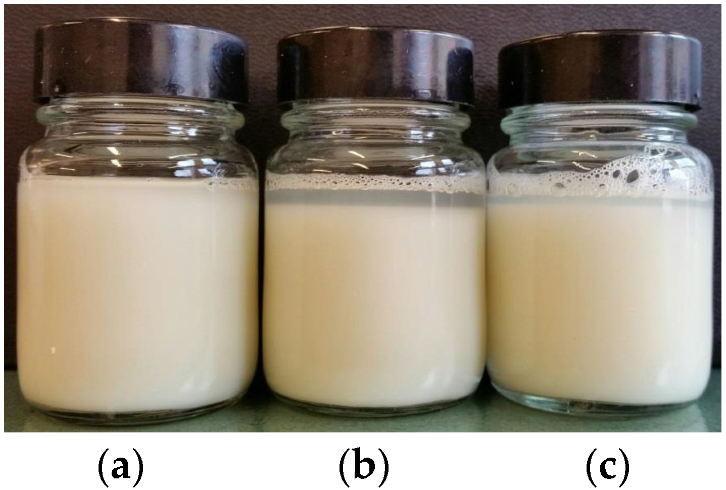
To make the initial FC-4 aqueous solution into which PTFE was added, 33.3 g/L FC-4 solid was dispersed in distilled water. The PTFE content in each bath was kept constant at 100 mL/L, and the amount of FC-4 aqueous solution was allowed to fluctuate to create the intended FC-4:PTFE ratios. Prior to carrying out the experiment, an observational trial was carried out over a period of 120 h to ensure compatibility of the FC-4:PTFE suspension. For the observational trial, PTFE was added to FC-4 in different ratios. Without mechanical agitation, there was a clear boundary between the translucent FC-4 layer and the milky PTFE solution, as shown in
Figure 1. Mechanical agitation was able to uniformly disperse the PTFE solution, and this mixture did not separate after continual observation over 120 h, suggesting the stability of mixture.
For both DC and PCP plating operations, the anode used was a pure silver plate (99.9% purity). The samples to be plated (substrate) were ANSI 304 stainless steel with dimensions of 25 mm × 12 mm × 1.1 mm with a 3 mm diameter hole used to hang the sample during plating. The power supply was remotely connected to a computer, which was used to generate a rectangular pulsed waveform for the PCP. To enable a comparison to be made with the previous results obtained from the DC plating operation, the pulse current density and pulse time were allowed to vary to maintain the same average current density of 0.2 A dm−2. This value is equal to the current density of the DCP process. For the PCP process, a frequency of 10 Hz with a rectangular wave form was used.
The coefficient of friction (CoF) was used to define the tribological characteristics of the Ag–PTFE MMC. The experiments were carried out using a linear tribometer as previously reported by Le et al. [
59]. The wear head used was a 3 mm Grade 10 AISI 52100 chrome steel spherical pin of hardness between 60 and 67 HRC. Ten wear cycles were carried out on the substrate (each cycle with approximately 6 mm sliding distance). After being tested on the tribometer, the wear track was visually examined using an Olympus BX-41M-LED optical microscope (Olympus, Tokyo, Japan), where the relevant wear track width measurements were taken.
Scanning Electron Microscopy (SEM), along with Energy Dispersive X-ray Spectroscopy (EDS) was carried out on the JEOL 7100 instrument (JEOL Ltd., Tokyo, Japan). SEM was used to examine the surface morphology of the plated deposit in order to better understand the effects of surfactant on the surface morphology of electrodeposited Ag–PTFE metal matrix composite using direct current and pulsed currents. EDS analysis, on the other hand, was used to determine the silver and PTFE content in both weight percentage (wt %) and atomic percentage (at %).
3. Results
3.1. Morphology and Compositions
The ratio between actual and theoretical deposit weight (otherwise known as current efficiency) was calculated based on Faraday’s law of electrolysis using measurements carried out on the anode electrode. According to Faraday’s law, the charge passed through the system will result in proportional amounts of substance being deposited or liberated. Current efficiencies of between 93%–97% were registered for the DCP process, whereas the PCP current efficiencies were between 60%–64%.
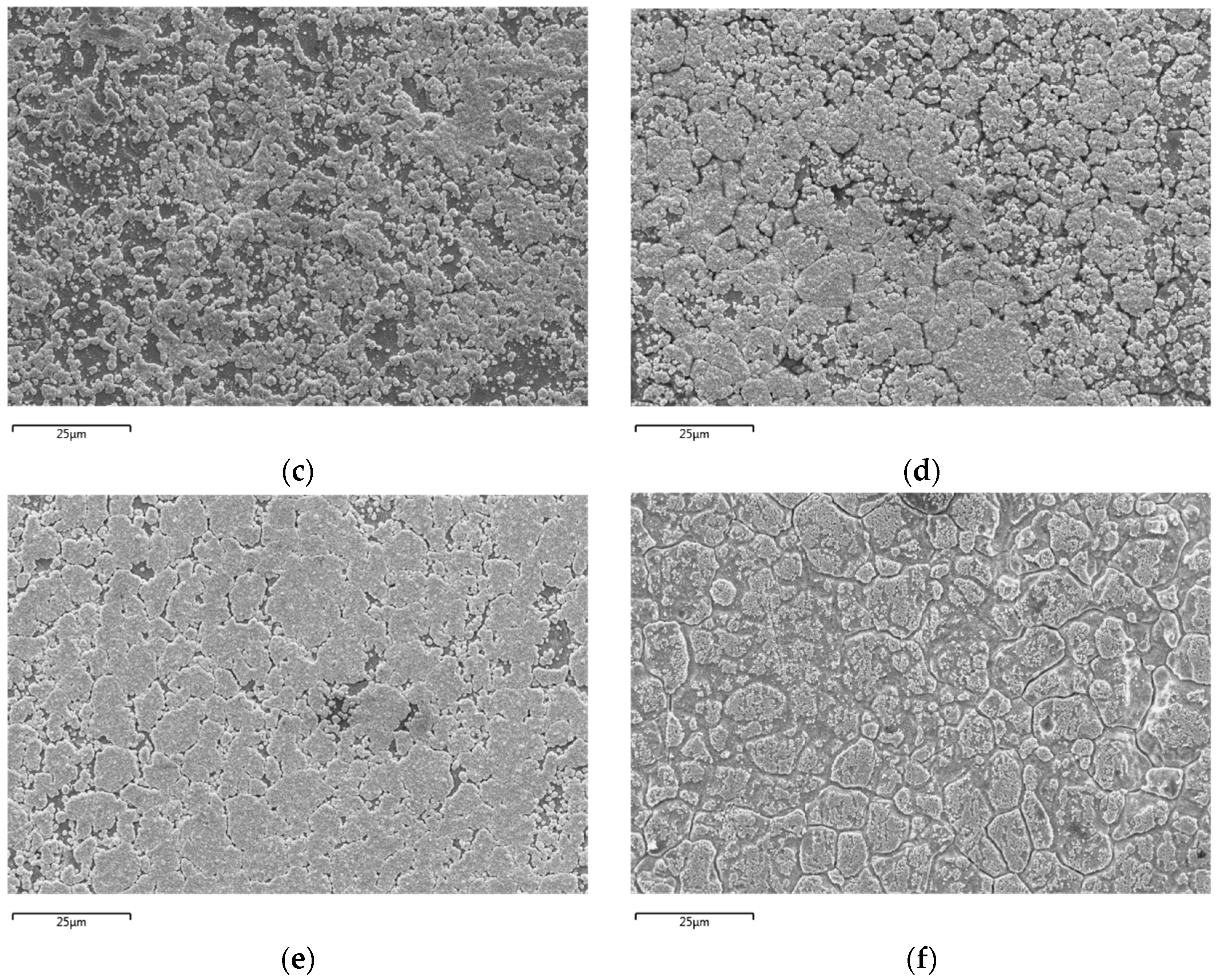
SEM analysis of the DCP samples with FC-4:PTFE ratios of 1:1, 1.5:1, and 2:1 at ×1000 magnification have notably different overall surface morphologies. For the 1:1 ratio sample, the plated layer primarily covers the surface of grains while having the grain boundaries clearly exposed. This is quite similar to the 2:1 ratio sample; however, with the 2:1 ratio sample, the plated layer is much more densely packed. On the other hand, the 1.5:1 ratio plating visually resembles spluttering, with the coating not clearly conforming to the grains of the substrate.
On the other hand, visual comparison of the PCP samples at ×1000 magnification show similarities between the surface morphology of plated samples at FC-4:PTFE ratios of 1:1 and 1.5:1; the major visual differences between these two samples however, lie in the coating density, where the plating at 1.5:1 is more densely packed. Meanwhile, the 2:1 ratio PCP sample is coated primarily on the surface of the grains, with the grain boundaries experiencing limited coverage and being clearly visible. The SEM images for both DCP and PCP samples are shown in
Figure 2.
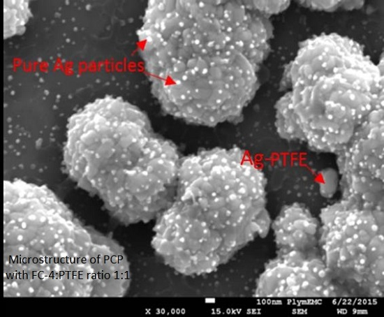
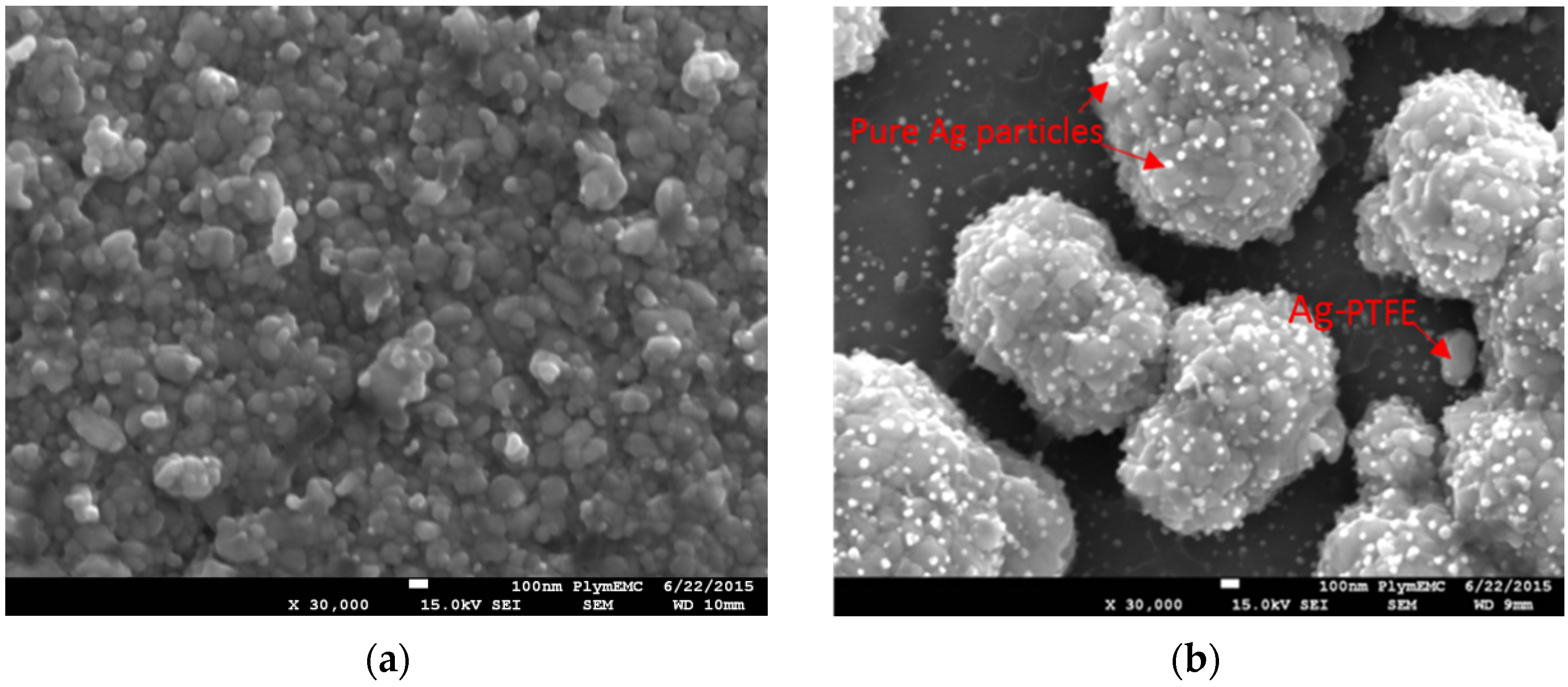
To better understand the differences between DCP and PCP at the different FC-4-to-PTFE ratios, the deposited particles were also analysed at ×30,000 magnification, as shown in
Figure 3, with
Figure 3b highlighting the PTFE and pure Ag particles. For all of the DCP samples, average plated particle sizes were approximately 100 nm, with bright particles <50 nm visible. The 1:1 ratio DCP sample had noticeably lower amounts of the bright (white) particles. With the 1.5:1 and 2:1 ratio DCP samples, the nanoparticles were fused together to create a larger spherical particle of approximately 1 µm in size. On the other hand, although the fusion of nanoparticles occurred on the 1:1 ratio DCP sample, they did not form the larger spherical cauliflower like particles, as observed with the other samples.
Observation of the PCP samples at ×30,000 magnification noted average particle sizes of approximately 100 nm across all samples, which was similar to that of the DCP samples. The bright particles were clearly visible on samples with FC-4:PTFE ratios of 1.5:1 and 2:1, with the 2:1 ratio sample having the highest concentration of these nanoparticles. The formation of fused larger particles was also apparent for the PCP samples. The fused particle size for 1:1 and 1.5:1 PCP samples were not dissimilar to that observed with the DCP ones, with a particle size of approximately 1 µm. On the other hand, although the fusion of particles occurred on the 2:1 PCP sample, these were of average sizes of approximately 300 nm, and the fusion of larger particles was in a linear fashion to create a uniform coating over the grain of the substrate.
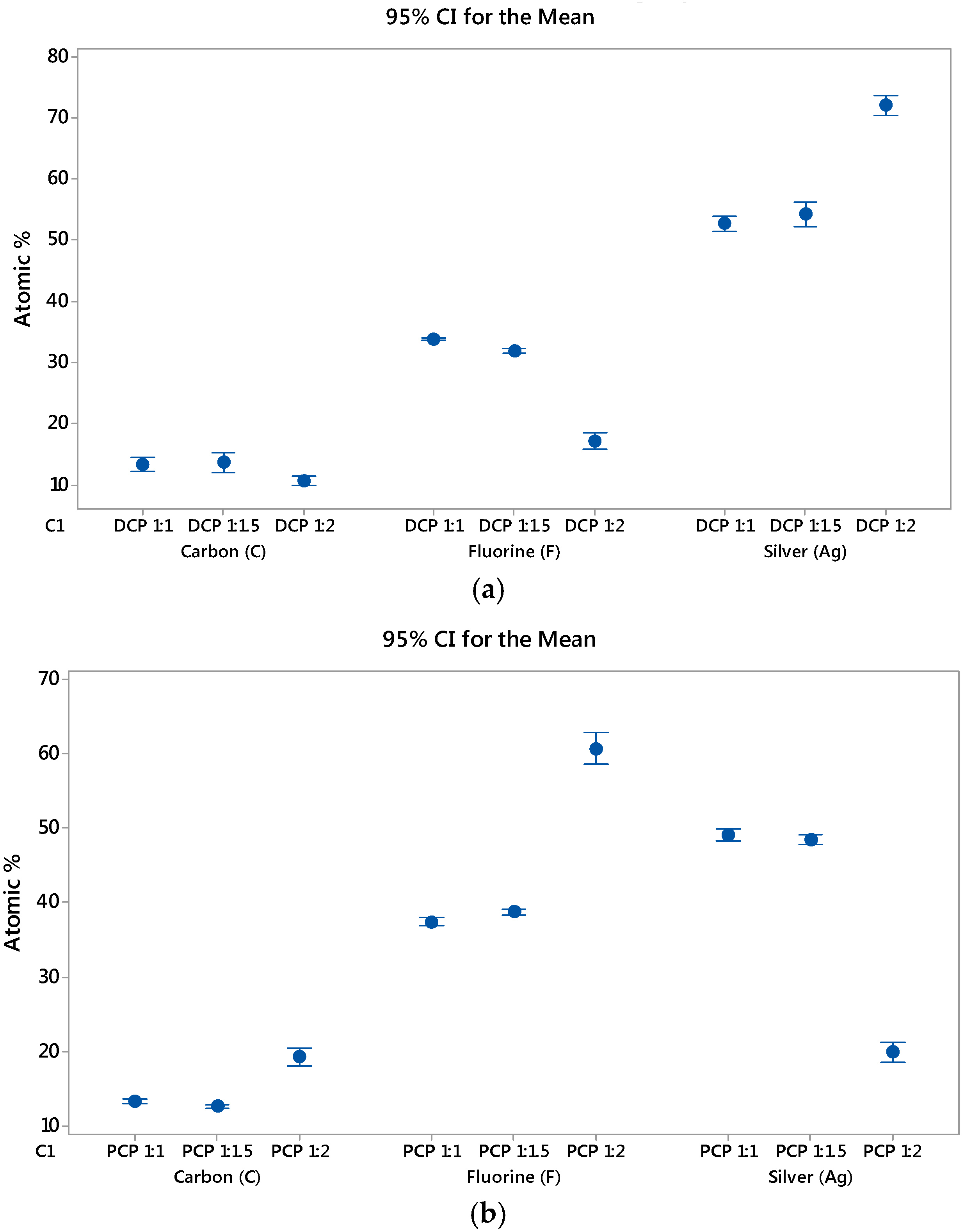
EDS was carried out using area analysis mode over three randomly selected sites at ×1000 magnification with averaged values used. wt % and at % data obtained from EDS was normalised to provide the appropriate values for quantitatively identifying the plated deposits of silver (Ag) and PTFE through its chemical composition of carbon (C) and fluorine (F) elements.
Figure 4 shows a typical output for EDS analysis. For the EDS analysis, as silver is denser than fluorine, at % is favoured for use in this paper to provide a more accurate representation of the elemental composition of the plating. Although both C and F elements are present for PTFE, F will be used for determination of the presence of PTFE, as carbon is also present in the substrate layer. The EDS was able to find silver, carbon, and fluorine elements on all the samples, suggesting successful incorporation of PTFE into the MMC and subsequent deposition on the substrate, as shown in
Figure 5.
EDS of DCP samples showed that although the amount of PTFE had gradually decreased between 1:1 and 1.5:1 ratio samples, this 5% decline in fluorine is within the error of measurements. On the other hand, there was a drastic decline of PTFE on the 2:1 ratio sample when compared with the 1:1 ratio sample. As such, there is a 50% reduction in the amount of PTFE incorporated into the 2:1 ratio DCP sample. The success of PTFE incorporation into the Ag–PTFE MMC can be defined by the inverse relationship between silver and fluorine elements from EDS, and the specific bath parameters for the 2:1 ratio DCP sample has resulted in unfavourable conditions for PTFE to be incorporated into the silver MMC.
EDS of PCP samples showed the opposite results to that of DCP. When comparing the PCP 1:1 and 1.5:1 ratio samples, the amount of PTFE on the plated samples increased by 5%. Instead of the 50% decline in PTFE seen between the 1:1 and 2:1 ratio samples for DCP, the 2:1 ratio PCP sample experienced a much more phenomenal increase of 162% over the 1:1 ratio PCP sample. The EDS analysis of samples has revealed the potential for increasing incorporation of the hydrophobic PTFE particles in the MMC through the use of FC-4 cationic surfactant. It is believed that the surfactant is able to convey a positive charge on the PTFE particles, thus promoting electrophoretic migration to the cathode during the electroplating process. Without the use of the surfactant, the PTFE particles would not be charged, and thus migration to the cathode would occur as a result of flow conditions inside the electroplating bath.
In understanding the differences observed for the 2:1 ratio sample under different plating methods, for PCP, a lower pulse frequency was favoured over a higher pulse frequency, as this would result in a longer cycle and longer off-time while keeping the duty cycle for the experiment constant throughout. This provides more time for the charged particles in the bath to migrate into positions that are more stable during the interval periods. The changes in the microstructure of the PCP deposits over DCP might be explained through the differences in limiting current density, which can be expressed as follows [
60]:
where,
n is the Number of electrons required to reduce one mole of metal;
F is Faraday’s constant;
D is the diffusivity of the dissolved metal;
Cbulk is the bulk concentration of the dissolved species; δ is the Diffusion boundary layer;
ton is the pulse-on time, where current reaches peak value.
The metals deposit at the pulse current density for PCP, which is a much higher value, even though the average current density corresponds to that used in DCP. This value of pulse current density will affect the composition of the deposit, and has previously been reported to produce electrodeposits that have different microstructures [
61].
3.2. Friction and Wear
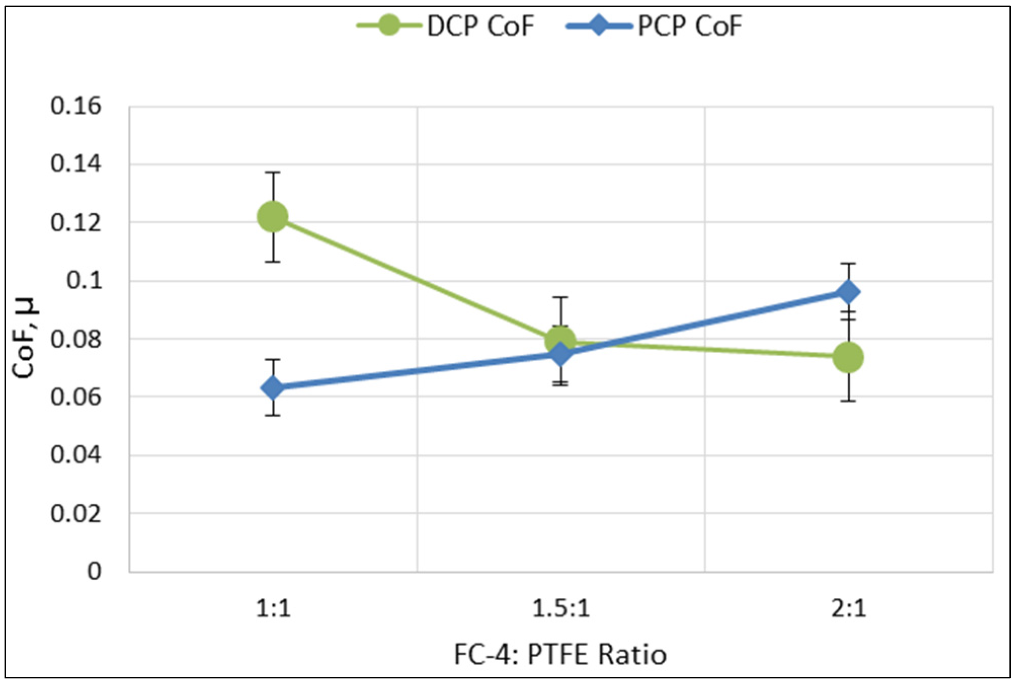
Tribological data in the form of friction coefficients (CoF) from each of the DCP and PCP samples was obtained over 30 cycles from three randomly selected sites (10 cycles per site), as described in a previous paper [
58]. The CoF shown in
Figure 6 was obtained by averaging the mean CoF values across the three sites. Based on this, there was a downward trend for the CoF values with increasing FC-4:PTFE ratio, with a range between 0.07 and 0.12. For PCP samples, there was an upward trend for the CoF values, with a range of between 0.06 and 0.09. In comparing both DCP and PCP samples, the DCP 1:1 ratio sample had the highest CoF value at 0.12, while the PCP 1:1 ratio sample had the lowest CoF value at 0.06.
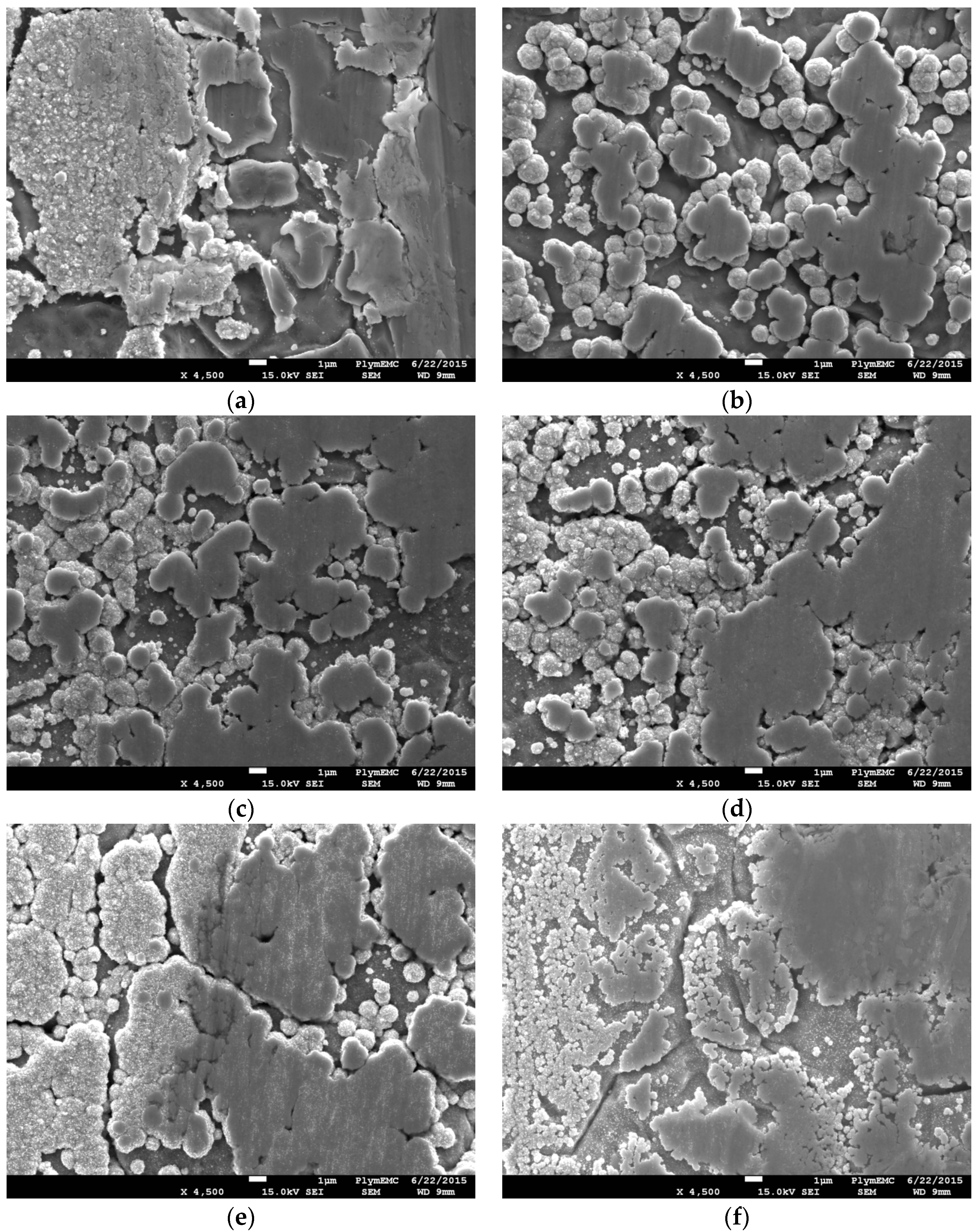
SEM was used to overcome the physical limitations of optical microscopy when it came to better understanding the tribological behaviour of the samples.
Figure 7 shows SEM micrographs of the wear track borders of both DCP and PCP samples at ×4500 magnification. It appears that the majority of coating from the DCP 1:1 sample was removed from the substrate with evidence of galling occurring. Galling has occurred due to the combination of adhesive and frictional forces between the sliding stainless steel surfaces with insufficient lubrication. The tearing of substrate crystal structure resulted in material transfer from the sample to the pin and an increase in the CoF value.
Consideration for the hardness of the coating has to be taken, as it plays a pivotal role in the friction and wear mechanism. Lower wear is typically associated with harder coatings, and it should be noted that both silver and PTFE fall into the category of soft coatings, where low friction applications are required. With this under consideration, PTFE has a hardness of between 5.9 and 6.5 HV, whereas the HV of pure silver is around five to six times that of PTFE. Data obtained from EDS analysis shows a trend of higher silver amounts (and thus harder coatings) being more resistant to wear when comparing across the same electrodeposition method. It is also important to note that as the wear increases, so does the contact area. Although all of the deposited coatings exhibit desirable CoF performances, the combination of Ag–PTFE shown in
Figure 7b (deposited using PCP) possesses the best combination of being sufficiently hard in resisting wear while the incorporated PTFE particles provide added lubricity. The wear resistance resulted in a relatively-consistent contact area throughout the experiment. On the other hand, the coatings that contained the most amount of embedded PTFE particles showed the worst wear resistance. Even though relatively large amounts of PTFE were contained in the layer, the PTFE would have been drawn from the bulk by the counter-surface in equally large amounts, resulting in its rapid depletion through wear. This is evident on
Figure 7f for PCP and
Figure 7a for DCP, which had exhibited the worst CoF performance among deposition methods.
All the other samples had coatings that still protected the substrate on the edges of the wear track, even after testing. Visual observation of the wear track micrographs showed an increasingly wear-resilient coated layer for DCP samples with increasing FC-4:PTFE ratios, which would explain the improved tribological performance. On the other hand, the PCP coating became easier to remove with increased FC-4:PTFE ratios, as a result of being softer. Taking into account the EDS data, although the coating for the PCP 2:1 sample was not fully removed, it contained the highest amount of PTFE, which is a relatively soft material that can be easily removed by the tribometer pin. In addition, visual comparison of the PCP wear track borders shows an increase in thinning of the coating with increasing FC-4:PTFE ratio.
These findings also suggest that the amount of foreign matter inclusion or presence of the foreign particles does not fully dictate the tribological behaviour of the coating. Although the PCP process is able to directly influence the deposited coating by increasing the amount of embedded PTFE, the wear performance of the coating is still dependent on other factors, such as the properties of the MMC deposit. This is in line with the findings of previous work carried out by Thiemig et al. [
22] and Zimmerman et al. [
23] to improve the performance of coatings, which concluded that the performance improvements were primarily due to changes in grain sizes or growth modes in the MMC, as opposed to the presence of foreign particles. The same phenomenon of changes in MMC growth sizes was also observed during the experiments.
4. Discussion and Conclusions
The work focused on the aspects of chemical changes through the addition of the cationic surfactant FC-4, as well as the changes in electrodeposition methods through the use of DCP and PCP. The findings suggest that the initial high concentration of PTFE nanoparticles in the electroplating bath was beneficial in the high incorporation rates of PTFE across both DCP and PCP methods, ranging from 17–61 at % (4–33 wt %). Furthermore, the use of PCP was clearly beneficial to the incorporation of PTFE nanoparticles in the MMC. Through the variation of electrodeposition methods (DCP/PCP), the opposite impact of PTFE incorporation into the Ag–PTFE MMC was observed as a result of differences in pulse current densities. Maintaining the same average current density throughout saw that when using DCP, the more FC-4 that was in solution, the lower the incorporation rate of PTFE in the MMC; whereas the opposite was true for the PCP method. The dramatic change of PTFE incorporation into the MMC was observed at FC-4:PTFE ratios of 2:1 for both DCP and PCP, where DCP experienced a decrease of 50% while PCP experienced an increase of 162% for incorporated PTFE, with the highest incorporation rate of PTFE achieved through the PCP 2:1 sample.
The tribological experiments showed that DCP and PCP samples exhibited an average CoF range of 0.06 to 0.12. It was concluded that:
The lowest CoF was obtained from a FC-4:PTFE ratio of 1:1 through PCP;
The highest CoF performances were obtained from a FC-4:PTFE ratio of 1:1 through DCP;
It is possible to reduce the utilisation of PTFE raw materials while increasing the incorporation rate of PTFE particles in an Ag–PTFE metal matrix nanocomposite through the use of FC-4 cationic surfactant;
PTFE particle incorporation is not the only factor that dictates tribological behaviour of the samples, and considerations have to be made for the deposit properties for tribological improvements to be made, such as hardness of the deposit, which can be controlled through deposition methods.
Future work on bath development could include the use of alternative non-cyanide silver baths including but not limited to sulphur-complexes. Furthermore, there is also the opportunity to utilize a rotating cylinder electrode to further study the effects of particle incorporation. Work around these areas could also lead to a study of the influences different bath types have towards the general and tribological properties of the deposit, which could lead to further opportunities in reducing coating thickness while exhibiting better or comparable performance for engineering applications.


