1. Background of Thin Film Coatings on Plastic Containers
Polymer materials have unique properties, such as being easy to shape, and are elastic to physical impacts compared to other types of materials, like metal, glass, and ceramics, and nowadays quite a wide variety of plastic containers are seen in the food and beverage industry. For example, PET (poly(ethylene terephthalate)) bottles are the most widely used package format in the soft drink segment and further use of PET bottles is expected both inside and beyond the soft drink segment [
1,
2].
From the view of package performance, light-weight, unbreakable, and transparent properties are favorable advantages of common plastic containers. To the contrary to these consumer benefits, gas permeability is a remarkable disadvantage of plastic containers compared to metal and glass containers [
3], which virtually eliminate gas permeation, except sealing parts where polymer materials are usually used.
Especially, the permeation of oxygen and carbon dioxide molecules often limits the shelf-life of sensitive products. One of the most sensitive products to gas permeation is beer. Beer is quite sensitive to oxidation, and also sensitive to carbon dioxide release. From the view point of shelf-life extension, the degree of gas barrier improvement is often expressed by BIF (barrier improvement factor) [
4]. The value of BIF can be calculated based on the gas transmission rate of normal container(s) divided by that of barrier improved container(s). PET bottles of single serve size require 10 or more times the oxygen barrier in BIF in order to achieve a realistic shelf-life of beer. Furthermore, they require seven or more times the carbon dioxide barrier in BIF if the equivalent shelf-life in glass bottles is demanded.
Since these sensitive products are seen quite often in our daily diet, like in juice, teas, seasoning, edible oil, and wine, as well as beer, significant effort has been made for improving the gas barrier performance of plastic containers. Among rigid containers used in the food and beverage industry, PET bottles are the most intensive category of plastic containers for gas barrier enhancement study because of their industrial scale of use. It should be stressed that the demand for high gas barrier PET bottles has been increasing because of the global trend in weight reduction, where thinner bottle walls show less gas barrier performance [
5], and of a gradual increase of the applications of PET bottle formats.
Based on these backgrounds, this paper reviews the past and recent progress of gas barrier enhanced PET bottles, especially gas barrier thin film coated bottles.
2. Approach to the Gas Barrier Enhancement of PET Bottles Other Than Thin Film Coating
Major technologies to enhance the gas barrier property of PET bottles used in today’s industry can be roughly classified into four categories, that is, (i) coating; (ii) multi-layer; (iii) blending; and (iv) oxygen scavengers, as illustrated in
Table 1. It should be noted that different approaches can be combined together. For example, the core layer explained below in the multi-layer approach may include oxygen scavengers, or the blending additives explained below are added in PET layers of multi-layer walls.
Table 1.
Rough classification of the current major gas barrier technologies for PET bottles [
6,
7].
The multi-layer approach employs at least one core layer with higher gas barrier properties placed between PET layers. The core layer(s) provides the majority of the gas barrier property of the whole bottle. Some specific grades of polyamides are often used for core layer materials, even though other materials had been attempted [
3,
8]. While the multi-layer approach is widely used in many industrial fields and its process control has been well established, economics due to the use of specific injection machines for multilayer preforms and of relatively expensive core-layer materials are the barrier to further distribution in the PET bottle industry. From a technical standpoint of view, the core layers are usually adjusted to occupy several percentages of the whole bottle weight to shape the bottle properly, and the core layers of a bottle usually do not exist near the mouth part and the center of the bottom part. These factors limit the maximum oxygen barrier property of multi-layered bottles compared to oxygen scavengers and coating approaches. In Japan, the market share of barrier PET bottles based on this approach has been decreasing.
In the blending approach, higher gas barrier materials are added into melted PET resin before the shaping process. The additives increase the gas barrier property of the whole bottle depending on the concentration in the PET matrix. Some specific grades of polyamides are often used for additive materials [
9], even though other materials had been attempted [
3,
10]. Due to the cost of additives and limited barrier performance compared to other approaches, the use of this approach is limited in these days in Japan. Additionally, in some countries such as Japan, possible mass use of polyamide additives is a concern to their recycling systems.
Oxygen scavengers are a type of additive which reacts with the oxygen permeant and results in restricting the passage of oxygen molecules through the bottle wall. The addition of a certain polyamide and transition metal complex into the PET matrix is an example of this approach [
11]. In ideal conditions, this approach can inhibit the increase of dissolved oxygen in the liquid content of the bottle. However, it makes it difficult for bottle manufactures to control the quality of their products as additive concentration and shaping conditions of bottles affects to each other. Some application may not accept the tint and haze due to typical types of scavenger additives.
3. Thin Film Coating for the Gas Barrier Enhancement of PET Bottles
Coating forms thin films over the surface of PET bottles. Dense structures of the thin films, typically several tens of nanometers in thickness, behave like glass or ceramics, and block the passage of gas permeants. The current approach generally uses two types of thin film species, that is, (A) carbon thin films, often described as diamond-like carbon (DLC) or a-C:H [
3,
4], or (B) silicate oxide thin films, often described as SiO
x, where
x is a number and often somewhere between 1.5 to 1.8 [
3,
12].
While each approach described in the previous chapter has its own advantages and disadvantages, the use of coating is an expanding trend, or is expected to expand [
13]. At least in the Japanese market, the trend is remarkable in recent years [
14]. One of the advantages in the coating approach is that relatively high gas barrier enhancement is possible to various gas components including oxygen, carbon dioxide, water vapor, and flavors. This favors the quality retention of beverages where quite complex combinations of flavors contribute to unique taste and mouth-feeling, for example, seen in wine and beer [
15,
16,
17]. Another advantage lies in high recyclability. While other categories of the gas barrier enhancement approach of PET bottles usually require several percentages of foreign materials in the PET matrix in terms of weight, the foreign materials derived from coating amount to be, at most, several parts per million in terms of weight. As a result, coated bottles are usually no problem in recycling of normal PET bottles even in the case of mass use. From an economic point of view, relatively high capital cost to install coating machines is disadvantageous to coating, and this can explain the cause of the relatively slow increase of the use of coated bottles. On the other hand, relatively low operation cost is advantageous, and, in the case with high operational efficiency, coating is expected to require the lowest operation cost [
6,
7,
8]. In brief, in the case where a remarkable increase of barrier PET bottles happens, especially involved with the mass use in beer and carbonated soft drinks, coating approaches are most likely to be accepted from the viewpoint of bottle performance, social systems, and economics. In other words, at present, coating can be considered to have the largest growth potential among the barrier enhancement technologies of PET bottles.
4. Current Methodology to Thin Film Formation onto PET Bottle Surface
While various techniques are known to form thin films on substrates, plasma assisted chemical vapor deposition (CVD) techniques are currently available for mass production machinery for gas barrier thin film coating of PET bottles. These techniques meet the requirements for food and beverage containers. At least several requirements are essential, as summarized in
Table 2.
Table 2.
Basic requirements for thin film coating to PET bottles.
Table 2.
Basic requirements for thin film coating to PET bottles.
| No. | Property | Reason | Corresponding Process Design |
|---|
| 1 | High gas barrier | For the flavor quality of the bottle content | Special configuration in coating chambers |
| 2 | Flexible | To withstand bottle deformation | Limited coating thickness and/or use of adhesion layer(s) |
| 3 | Thin and clear | For recycling and bottle appearance | Limited coating thickness |
| 4 | Physically and chemically stable to the bottle content | For safety to human and the flavor quality of the bottle content | Choice of thin film species in case of inside coating |
| 5 | Short process time | Economics | Optimization between barrier enhancement and throughput |
One of major conceivable reasons of the use of plasma-assisted CVD lies in low heat load to the substrate. The deformation of the containers is likely to occur when the temperature of the substrate increases above its glass transition temperature which, in the case of polyester-based plastic containers like PET and PLA bottles is 70–80 °C, and 60–70 °C, respectively [
18].
A second conceivable reason is that plasma can relatively readily occur inside a bottle. While coating may be applied to the outer surface of a bottle, these types of technologies involve some difficulty to protect the physical damage to the coating during production in filling lines and transportation to retailers, and also to control coating conditions along with accumulating coating dusts inside vacuum chambers. On the other hand, in the case of coating on the inner surface of a bottle, the thin film is protected with the bottle wall from physical impacts from the outside of the bottle, and most coating dusts can be deposited inside the bottle and removed from the vacuum chamber. Physical impacts may be a concern even with the internal coating due to known “abuse”, while typical production and transportation processes seem harmless to the barrier performance of the coating inside the bottle, as far as coated bottles were observed in Japanese market. Additionally, it should be noted that dust control is significantly important for continuous production which might last 20 h or longer. In the case of coatings over the inner surface of containers, thin films tend to come in contact with food and beverages, and are required to have physio-chemical stability which secures the safety to human diet.
The third reason is the relatively short process time for thin film formation. Usually, thin films of 10–100 nm in thickness are used in current technologies. Coating thickness is determined, depending on thin film species, based on economics and the optimal thickness for gas barrier properties [
2,
12]. It should be noted that an excessively thin film lacks in barrier property, and an excessively thick film decreases in visual and barrier quality due to the occurrence of cracks [
2,
19].
As a result, based on the deposition rates of roughly 2–60 nm per seconds, 1–5 s are taken for thin film deposition under vacuum conditions, such as 1–20 Pa before coating and 5–30 Pa during coating. The whole process time ranges from 6–30 s per one bottle coating, depending on coating conditions and machine configurations. These process conditions are summarized in
Table 3.
Table 3.
Summary of plasma assisted CVD techniques used for PET bottle coating.
Table 3.
Summary of plasma assisted CVD techniques used for PET bottle coating.
| No. | Coating Process/Device | Variations |
|---|
| 1 | Power frequency | 2.45 GHz, 13.56MHz, or 6.0 MHz |
| 2 | Thin film species | Carbon (DLC) or SiOx |
| 3 | Material gas | Acetylene, HMDSO, HMDSN |
| 4 | Coating chambers | With electrodes (capacitative systems), or without electrodes (inductive systems) |
| 5 | Vacuum pressure | Around 10 Pa |
| 6 | Coating time | Around 1–5 s |
| 7 | Coating surface | Inside of bottles |
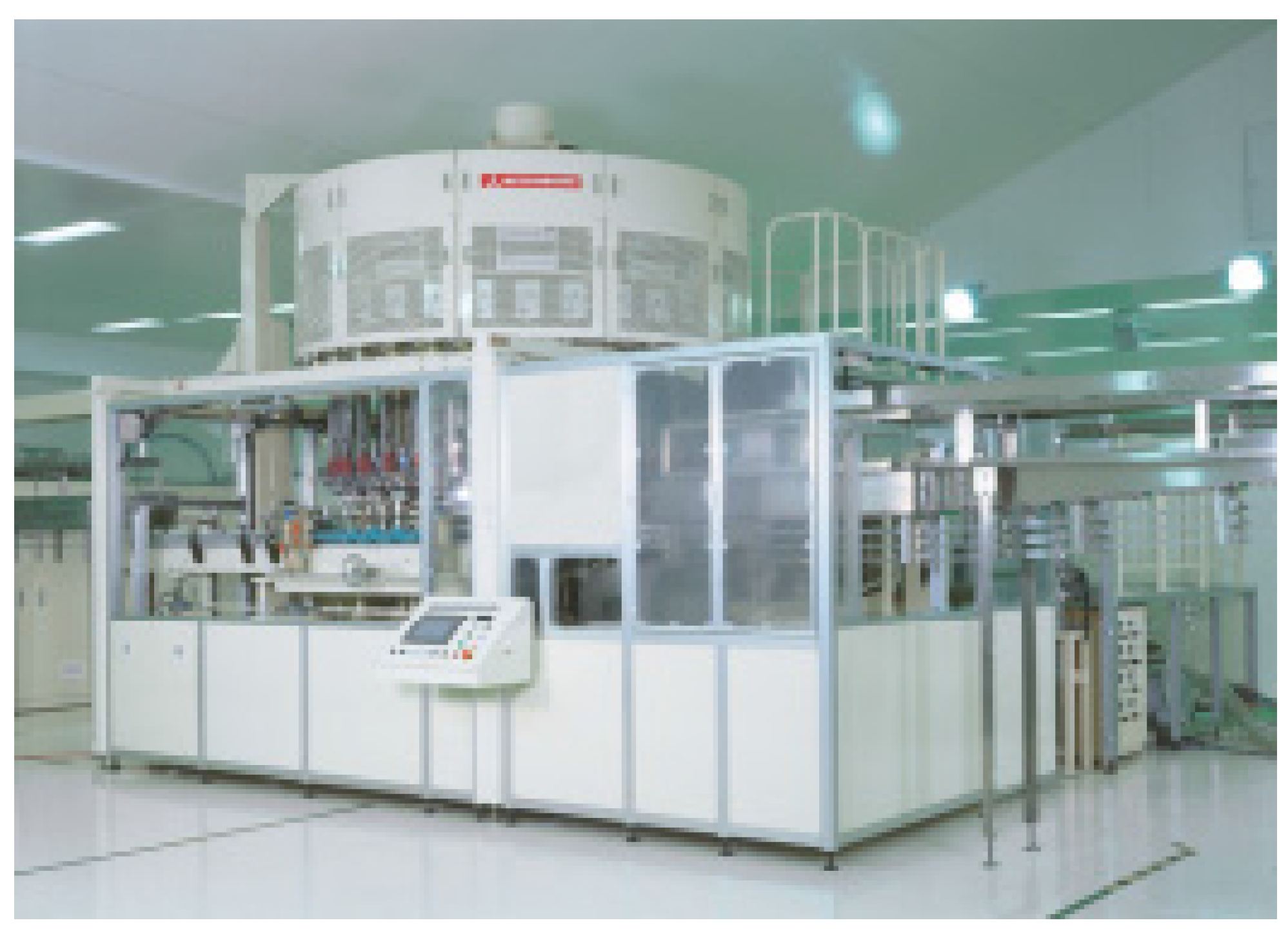
As a result, high throughput machines with a capacity of up to 40,000 bottles per hour have been in operation in soft drink and beer segments based on industriall-realistic economics.
Figure 1 and
Table 4 show an example of high throughput machine and details on coating process and performance, respectively, based on Kirin’s DLC coating method [
20].
Figure 1.
Example of high throughput rotary coating machine for PET bottles (photo provided by courtesy of Mitsubishi Heavy Industry Food and Package Co., Ltd., Nagoya, Japan).
Figure 1.
Example of high throughput rotary coating machine for PET bottles (photo provided by courtesy of Mitsubishi Heavy Industry Food and Package Co., Ltd., Nagoya, Japan).
Table 4.
Typical process conditions for DLC coating to PET bottles [
20].
Table 4.
Typical process conditions for DLC coating to PET bottles [20].
| Process Parameter | Conditions |
| Power frequency | 13.56 MHz, or 6.0 MHz |
| Power outlet | 300–2500 W |
| Material gas | Acetylene |
| Gas flow rate | 10–300 sccm |
| Vacuum pressure | 5–10 Pa |
| Coating time | 1–2 s |
| Resultant Properties | Performance |
| Deposition rate | Around 10 nm/s |
| Gas barrier improvement | Oxygen, Carbon dioxide, water vapor, and flavor components |
| Applicable container | 1–5000 mL |
| Applicable filling manner | Aseptic to hot filling |
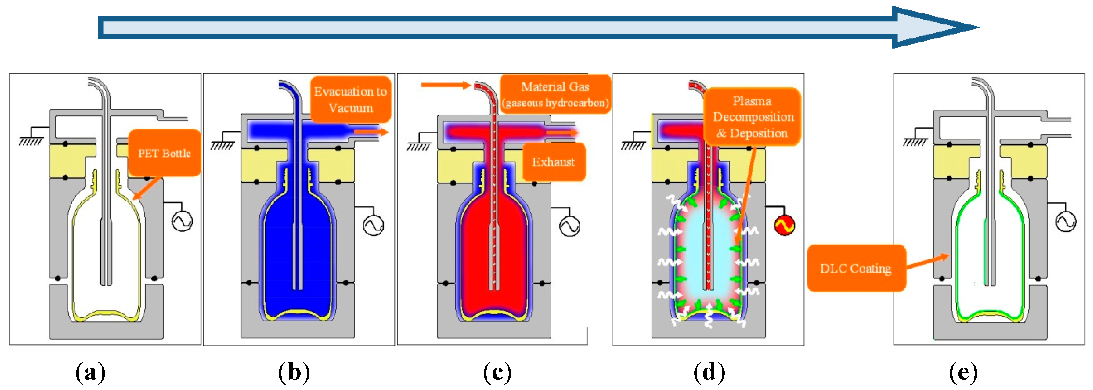
Although differences in processes for coating bottles can be found among the current plasma-assisted CVD technologies, they have the basic process concept in common, that is, (i) to place a bottle into a vacuum chamber, and to vacuum the chamber; (ii) to supply material gas into the bottle; (iii) to apply electromagnetic wave to the inside of the bottle so that the material gas is decomposed into a plasma state; (iv) to allow the plasma to form a thin film on the inner surface of the bottle; and (v) to release the chamber to the atmospheric pressure, and to remove the coated bottle (as summarized in
Figure 2). Obviously, these processes can be repeated continuously.
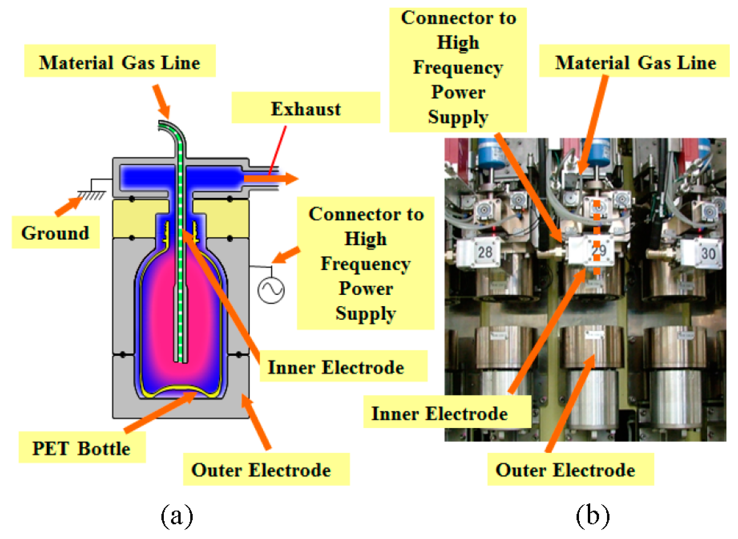
Figure 2 and
Figure 3 show an example of the coating processes of Kirin’s DLC coating method and the coating system, respectively. In this system, an outer electrode functions as a part of vacuum chamber. Moreover, its internal shape similar to the bottle shape enables evenly distributed coating over the entire part of the bottle, based on that distance between the inner surface of the outer electrode and the bottle can control the voltage of the bottle surface and the resultant plasma distribution.
Figure 2.
Schematic plasma CVD process for coating plastic bottles in case of Kirin’s DLC coating. (a) Bottle placement into the coating chamber and vacuuming; (b) material gas supply; (c) power application to the coating chamber; (d) thin film deposition; and (e) pressure release and bottle removal from the coating chamber.
Figure 3.
Example of the components of coating system for PET bottles: (a) schematic model; and (b) the corresponding part of the production machines (photo provided by courtesy of Mitsubishi Heavy Industry Food and Package Co., Ltd., Nagoya, Japan).
Figure 3.
Example of the components of coating system for PET bottles: (a) schematic model; and (b) the corresponding part of the production machines (photo provided by courtesy of Mitsubishi Heavy Industry Food and Package Co., Ltd., Nagoya, Japan).
This basic process concept for hollow containers was seen at least as early as the 1980s, and some coating machines intended for commercial use were introduced early in 1990s [
21,
22], and various process conditions, including different material gas species, have been tried. As a result, the main difference of the processes among the current coating technologies for PET bottles, in general, lies in the material gas species and the frequency of power used to create plasma states.
Nowadays, types of metal oxides and nitrides, as well as carbons, are known to be possible to function as gas barrier thin films [
23]. Carbon and silicate oxide thin films are, however, only two thin film materials available for mass production technologies for gas barrier enhanced PET bottles. The major reasons for the use of carbon and silicate oxide thin films for PET bottle applications lie in safety in food contact, the availability and relatively easy handling of material gas, and the economics to achieve sufficient gas barrier performance. Although aluminum and aluminum oxide thin films have a long history of use for the gas barrier enhancement of film and sheet applications [
24], appropriate material gas species and coating processes for container applications have not yet been found.
In addition, the current plasma assisted CVD processes which are practical in the mass production can be found in vacuum conditions. Although it has been proved that certain atmospheric plasma-assisted CVD techniques can form gas barrier carbon and silicate oxide thin films based on dielectric barrier discharge techniques [
25], their technical problems, such as dimensional limits, remain yet unsolved for the application of three-dimensional objects like PET bottles.
5. Difference in and between Carbon and Silicate Oxide Coatings
The current commercial carbon thin films have a slight, brownish to golden, tint [
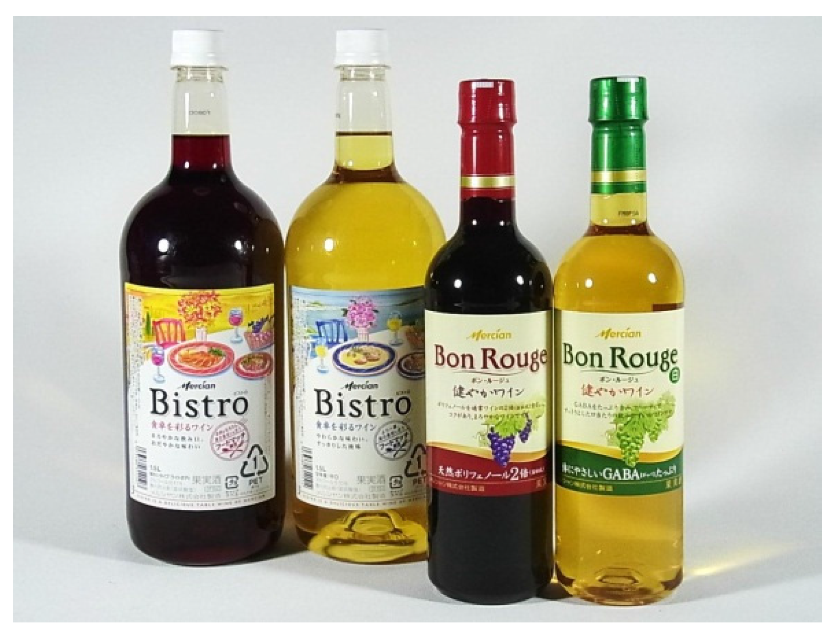
26]. Although this may restrict applicable product categories of carbon coated PET bottles, from the viewpoint of the visual quality of products, the degree of the tint appears to position within the scope of consumer acceptance, based on the commercial products of white wine (
Figure 4) and edible oil categories in the Japanese market.
Figure 4.
Example of DLC coated bottles for wine.
Figure 4.
Example of DLC coated bottles for wine.
In case of beverage and liquor market in Japan, carbon coating is more often seen than silicate oxide coating in spite of the abovementioned disadvantage to carbon coating. The reason might be found in that carbon thin films are readily applicable to various product categories because carbon coating is inert to food and beverage solutions as long as the PET substrate is stable. On the other hand, some more remarkable limit in applicable product properties is known in typical silicate oxide coating. The gas barrier property of silicate oxide coatings may be decreased in contact with some solutions, for example, beverages of pH close to neutral [
27].
C
2H
2 (acetylene) is the main material gas for carbon thin films for gas barrier-enhanced PET bottles. Derived from the hydrogen contained in acetylene molecules, the resultant carbon thin films contain hydrogen components up to 40% in atomic percentage. ERDA (Elastic Recoil Detection Analysis) analyses showed oxygen components up to 10% may be present in the carbon thin films [
4,
28], which is considered to be mainly derived from water vapor from PET substrates. The advantage of the use of acetylene lies in high deposition rates and economics, while CH
4 (methane) is used in many studies [
4,
26]. At least carbon thin films derived from acetylene contain the carbon bonding of
sp3,
sp2, and
sp1, based on XPS and FTIR studies [
22]. In the Japanese market, carbon-coated PET bottles are derived from Kirin’s DLC and Sidel’s Actis™ technologies [
14].
HMDSO (hexa-metyl-di-siloxan) and HMDSN (hexa-metyl-di-silazane) are the main material gases for silicate oxide thin films with aid of the controlled supply of oxygen. Based on the ratio in the mass flow of the material gas to oxygen and other conditions, the resultant thin films have different components consisting of silicate, carbon, oxygen, and hydrogen [
29]. The components have impacts on gas barrier properties and stability in contact with beverage solutions, and sometimes also on tint. In the case with commercial gas barrier silicate oxide, thin films are totally colorless in visual observation. In the Japanese market, silicate oxide-coated PET bottles can be mainly seen in domestic edible oil and wine products, and rarely seen in imported carbonated water. Those bottles are derived from Toyo Seikan’s Sibird™, Toppan’s GL-C™, and KHS’s Plasmax™ technologies [
14].
From the viewpoint of the frequency of power used to cause the plasma states of material gas supplied, radio frequency (13.56 MHz) and microwave (2.45 MHz) are used in commercial technologies. The use of radio frequencies usually leads to a bi-electrode system, in other words, a type of capacitively-coupled plasma system, where sheath voltage and the resultant ion impact over the surface of the substrate can be controlled relatively precise manner [
28]. It can be expressed that the use of these systems involves both merits and demerits to machine users. Examples of the merits are possible improvement in the performance of coating and stable application to relatively small or large containers, while those of the demerits are the possible increase of the change of mechanical parts for the application to containers of different shapes and sizes.
6. Recent Advancement in Commercialized Technologies for Coating Plastic Containers
In spite of the different nature of carbon and silicate oxide thin films as described above, it can be said that the difference between the two thin films is decreasing in the recent technical advancement.
It is obviously conceivable that the optimization of process conditions in parallel to the improvement in machinery has been performed in each technology, and as a result, deposition time has been shortened while the barrier properties of PET bottles coated are maintained or even improved. It is supposed that typical process conditions, including vacuum pressure, gas flow rate, and power application have been optimized. As a result, carbon coating has been less colored, and widened its applications (as shown in
Figure 2). In the same way, silicate oxide coating has clarified and mitigated its limitation in applications, and widened its applications. In the case of the Japanese market, the use of coating technologies has been rapidly increased in recent years and, at present coating is the most abundant among technologies, compared to other gas barrier enhancement technologies applied to PET bottles [
14].
An example of technological advancement has been found in the appropriate use of dielectric materials along electrodes in Kirin’s DLC coating technology [
30], and the modification of power frequency. Conventionally, this technology employed 13.56 MHz for power frequency and outer electrodes made of metal (conductive materials) parts only. Recently, power frequency was confirmed as one of the significant process parameters [
28]. The use of 6 MHz for power frequency and outer electrodes fully or partially covered with dielectric material parts has been proposed in order to facilitate finding the appropriate process conditions for high gas barrier coatings (as shown in
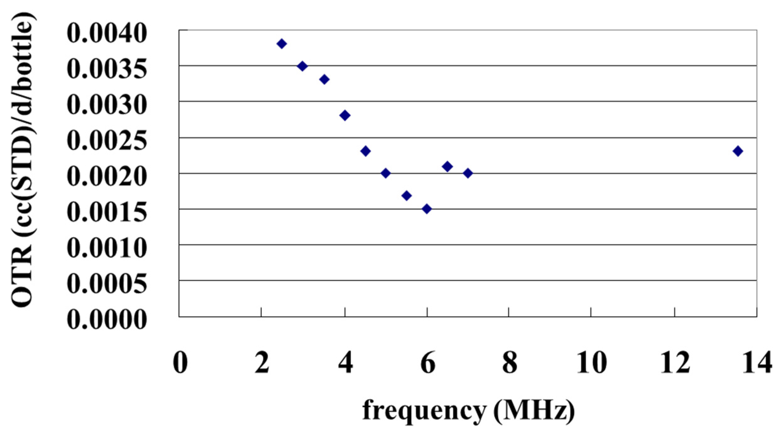
Figure 5) in addition to a decreased change of electrode parts for bottles of different shape and size. The results of the observation of coating thickness and plasma light emission indicate that the reason why 6 MHz power frequency showed the lowest gas barrier performance lies in the optimized spatial distribution of plasma. Compared to plasma produced with 13.56 MHz, where the plasma tends to concentrate around the neck part of the bottle, it seems that plasma with a lower frequency provides higher ion impacts to the PET substrate and the resultant secondary electrons modify the spatial distribution of the plasma to the direction of the bottom part of the bottle.
Figure 5.
Example of the impact on power frequency to the performance of coated bottles. 500 mL PET bottles were coated with DLC using different power frequency ranging from 2.5 MHz to 13.56 MHz, and the oxygen transmission rate (OTR) of these bottles were measured. Optimized power frequency was found at 6.0 MHz in terms of OTR. The measurement of OTR was performed based on ASTM F1307 [
31] method using an Oxran 2/21 device, Mocon Co., Ltd., (Brooklyn Park, MN, USA) under conditions of 23 °C and 90% relative humidity.
Another example has been found in the modification in the manner of material gas and oxygen supply during the coating process of KHS’s Plasmax™. This technology is called Plasmax Plus™. Due to an extra carbon-rich layer formed on the conventional silicate oxide layer, the resultant coating can be stable in contact with solutions of pH close to neutral, which deteriorates the performance of coating based on the conventional process. Interestingly, the new coating manner requires no machinery modification [
27].
7. Possible Near Future Advancement in This Field
The above description in this review mainly covered a brief history of gas barrier enhancement of PET bottles through plasma-assisted CVD techniques. On the other hand, a lot of effort has been made to other types of plastic containers and novel approaches to gas barrier enhancement.
Although the current era where PET bottles are the most abundant package format of rigid plastic containers is likely to last in this and the following decades because of their industrially-favorable balance between performance and economics, other plastic materials also have demands for functional thin film coating. Some polyolefins, such as PE (poly(ethylene)) and PP (poly(propylene)), are quite useful materials while the lack of oxygen and other barrier properties limits their benefits. For possible example, coated PP bottles or jars could keep the flavor quality of filled contents for certain extended periods of time in addition to high heat resistance, compared to PET containers, which are limited in applications below the boiling temperature of water.
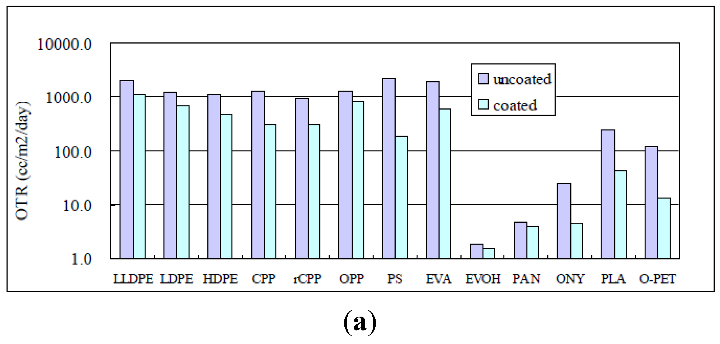
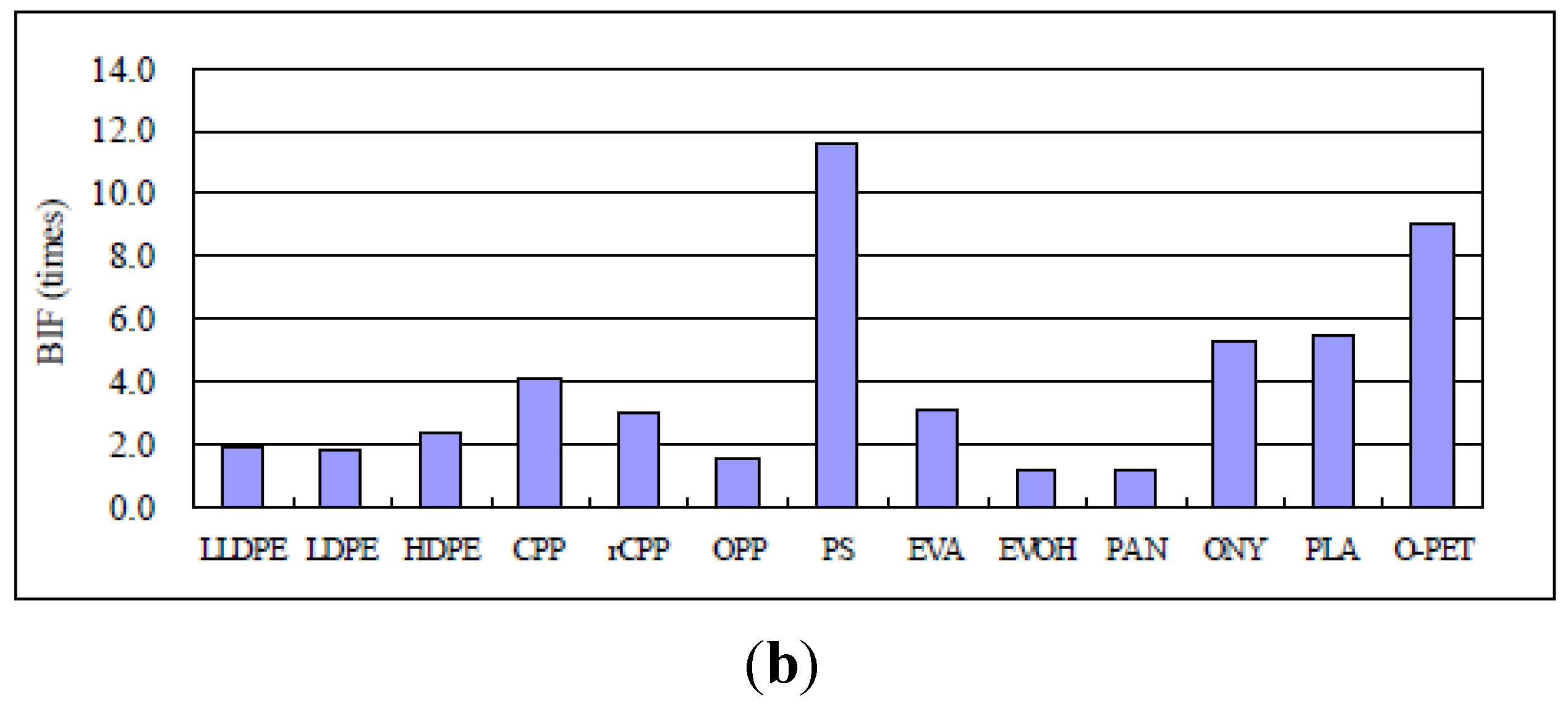
The authors found a remarkable difference in the degree of oxygen gas barrier enhancement with DLC coating formed on various kinds of plastic film substrates, as shown in
Table 5 and
Figure 6. However, a positron annihilation [
32] study by the authors indicates that, on these substrates, DLC coating can be formed homogeneously in terms of free volume, as shown in
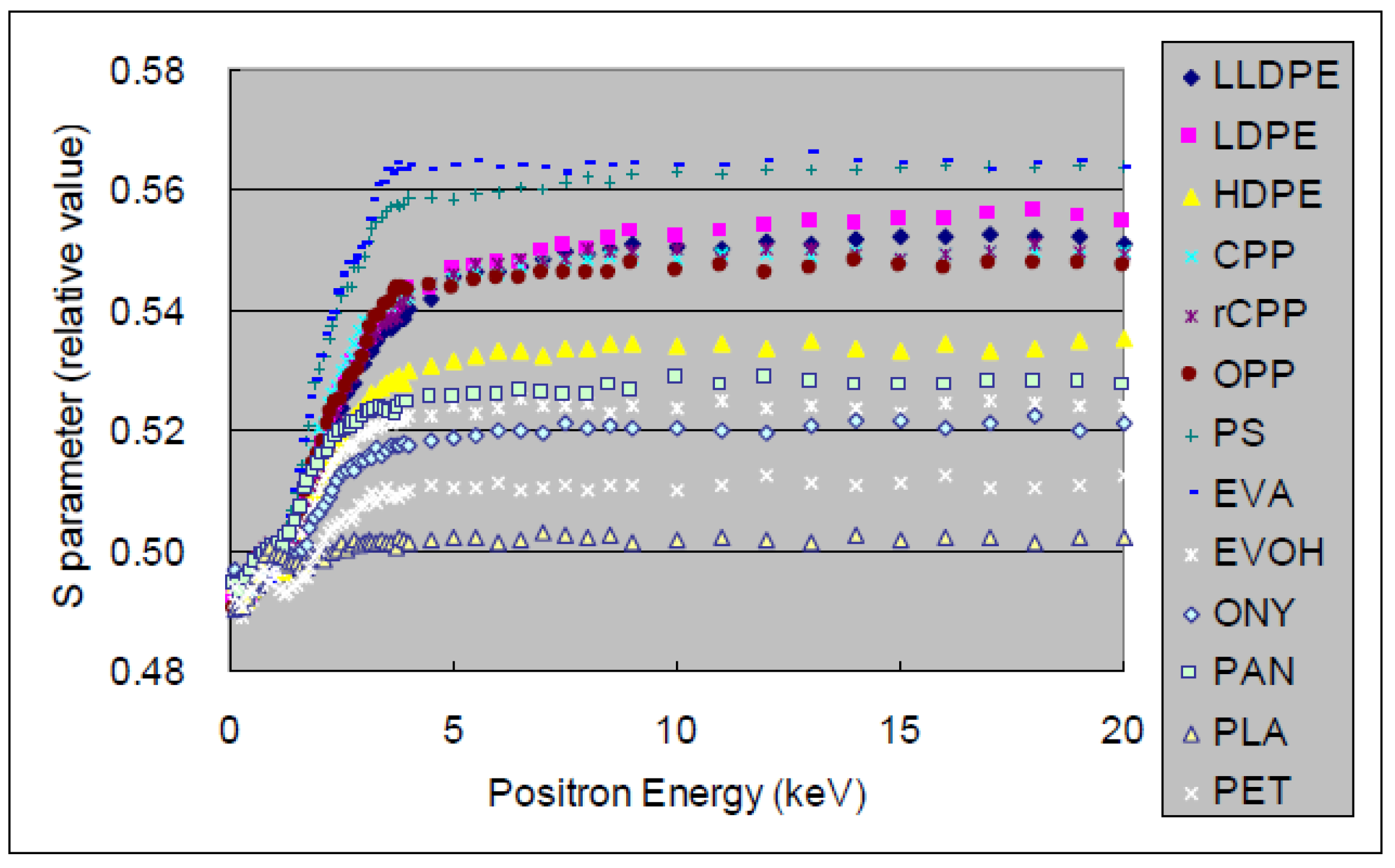
Figure 7. The positron annihilation method is based on a phenomenon where positrons implanted into a condensed matter annihilate with an electron and emits two 511-keV γ quanta. The spectra of γ energy, including the Doppler shift, are characterized by the S parameter, which mainly reflects changes due to the annihilation of positron-electron pairs with a low-momentum distribution. For amorphous materials, positronium (Ps: a hydrogen-like bound state between a positron and an electron) may form in open spaces (or free volumes).
Figure 7 clearly shows that DLC films has a small S parameter, compared to polymer substrates, and that thin films of small free volume can function as barriers against gas permeation. Empirically, packages made of PE and PP tends to have relatively rough surface, and rough surface is considered to lead to significant defects in coating. When the surface of them and PET bottles is observed using an atomic force microscopy, the
Ra of 1 μm square is usually 30–100 nm and less than 1 nm, respectively. A result of wet coating approach [
33] supports this concept, where a specific type of organosilane materials placed between DLC thin films and PP substrates remarkably enhanced oxygen barrier property, even though the organosilane layer itself did not have a significant barrier property to the PP substrate. It should be noted that, when the surface of the organosilane layer is observed with an atomic force microscopy, the
Ra of 1 μm square is usually around 1 nm. In this case, the smoothed surface with an increased anti-crack property due to the organosilane layer caused the enhancement of the coating. These results suggest the interface between thin films and substrates plays a crucial role on the enhancement of gas barrier property with dense thin film coating, and technologies for surface conditions are considered to be a key for the future commercialization of coated containers made of various plastics such as PE and PP.
In the other way, a novel approach to gas barrier thin film coating has been proposed, where a hot wire or catalytic CVD technique is applied to bottle coating in an attempt to achieve decreased installing expenditure based on the simple configuration of coating machines compared to that of conventional plasma assisted CVD machines. Furthermore, the application of this technique can produce unique gas barrier coating to PET bottles, like an intermediate between carbon and silicate oxide thin films [
34]. Since the machine installation cost seems to be the bottleneck to further distribution of thin film coating technologies, significantly low cost machinery may be a remarkable breakthrough in this field.
Table 5.
List of plastic materials used for comparing the degree of gas barrier enhancement with DLC coating.
Table 5.
List of plastic materials used for comparing the degree of gas barrier enhancement with DLC coating.
| Material | Abbreviation | Manufacturer | Type | Thickness |
|---|
| linear low-density poly(ethylene) | LLDPE | Toyobo Co., Ltd. | L6102 | 30 µm |
| low-density poly(ethtlene) | LDPE | – | Type S-1 | 40 µm |
| high-density poly(ethtlene) | HDPE | Mitsui-Toatsu Pleatec Co., Ltd. | Hiburon | 25 µm |
| cast poly(propylene) | CPP | Toyobo Co., Ltd. | P1128 | 18 µm |
| retortable cast (propylene) | rCPP | Toyobo Co., Ltd. | P1153 | 40 µm |
| Oriented poly(propylene) | OPP | Toyobo Co., Ltd. | P2108 | 40 µm |
| poly(stylene) | OPS | Toyo Chemical Co., Ltd. | Hallen L | 25 µm |
| poly(vinyl acetate) | EVA | Kaito Chemical Industry Co., Ltd. | Type E-30 | 30 µm |
| Poly(ethylene)-poly(vinyl acetate) | EVOH | Kuraray Co., Ltd. | Eval EF-F | 30 µm |
| Oriented polyamid | ONY | Toyobo Co., Ltd. | N1100 | 30 µm |
| poly(acrylo nitril) | PAN | Mitsui-Toatsu Pleatec Co., Ltd. | Zecron | 20 µm |
| poly(lactic acid) | PLA | Mitsubishi Plastics Co., Ltd. | – | 50 µm |
| Oriented poly(ethylene terephthalate) | PET | Toyobo Co., Ltd. | ES100 | 12 µm |
Figure 6.
Comparison of (
a) the oxygen transmission rate (OTR); and (
b) BIF of DLC coating on different plastic films. Samples of 40 mm square size were placed on the center of body part of 500 mL PET bottles were coated and measured based on the ASTM D3985 method using Oxtran 2/21 devices, Mocon Co., Ltd. (Brooklyn Park, MN, USA), under conditions of 23 °C and 90% relative humidity, in the same manner in a previous study [
28].
Figure 7.
Depth profile of the positron annihilation of DLC coated samples. The
S parameter of DLC coating (see the region of less than 1.5 keV) and plastic substrates (see the region of more than in 5.0 keV) was measured in the same manner in a previous study [
28] for observing the relative free volume of DLC coating layers.
The above discussion on near future technologies indicates a high potential of further advancement in thin film coating technologies for hollow plastic containers in this field, including applications to food and beverage industry.


